EP2207161A2 - Display apparatus, video generation apparatus, and method thereof - Google Patents
Display apparatus, video generation apparatus, and method thereof Download PDFInfo
- Publication number
- EP2207161A2 EP2207161A2 EP09003018A EP09003018A EP2207161A2 EP 2207161 A2 EP2207161 A2 EP 2207161A2 EP 09003018 A EP09003018 A EP 09003018A EP 09003018 A EP09003018 A EP 09003018A EP 2207161 A2 EP2207161 A2 EP 2207161A2
- Authority
- EP
- European Patent Office
- Prior art keywords
- video
- lines
- video stream
- frame
- display apparatus
- Prior art date
- Legal status (The legal status is an assumption and is not a legal conclusion. Google has not performed a legal analysis and makes no representation as to the accuracy of the status listed.)
- Withdrawn
Links
Images


Classifications
-
- G—PHYSICS
- G09—EDUCATION; CRYPTOGRAPHY; DISPLAY; ADVERTISING; SEALS
- G09G—ARRANGEMENTS OR CIRCUITS FOR CONTROL OF INDICATING DEVICES USING STATIC MEANS TO PRESENT VARIABLE INFORMATION
- G09G5/00—Control arrangements or circuits for visual indicators common to cathode-ray tube indicators and other visual indicators
- G09G5/003—Details of a display terminal, the details relating to the control arrangement of the display terminal and to the interfaces thereto
- G09G5/005—Adapting incoming signals to the display format of the display terminal
-
- G—PHYSICS
- G09—EDUCATION; CRYPTOGRAPHY; DISPLAY; ADVERTISING; SEALS
- G09G—ARRANGEMENTS OR CIRCUITS FOR CONTROL OF INDICATING DEVICES USING STATIC MEANS TO PRESENT VARIABLE INFORMATION
- G09G2310/00—Command of the display device
- G09G2310/02—Addressing, scanning or driving the display screen or processing steps related thereto
-
- G—PHYSICS
- G09—EDUCATION; CRYPTOGRAPHY; DISPLAY; ADVERTISING; SEALS
- G09G—ARRANGEMENTS OR CIRCUITS FOR CONTROL OF INDICATING DEVICES USING STATIC MEANS TO PRESENT VARIABLE INFORMATION
- G09G2310/00—Command of the display device
- G09G2310/08—Details of timing specific for flat panels, other than clock recovery
-
- G—PHYSICS
- G09—EDUCATION; CRYPTOGRAPHY; DISPLAY; ADVERTISING; SEALS
- G09G—ARRANGEMENTS OR CIRCUITS FOR CONTROL OF INDICATING DEVICES USING STATIC MEANS TO PRESENT VARIABLE INFORMATION
- G09G2340/00—Aspects of display data processing
- G09G2340/04—Changes in size, position or resolution of an image
- G09G2340/0407—Resolution change, inclusive of the use of different resolutions for different screen areas
- G09G2340/0414—Vertical resolution change
Definitions
- the present invention relates to a video generation apparatus, a display apparatus and a video generation method for scaling processing in video processing according to the pre-characterizing clauses of claims 1, 12, and 17.
- Format conversion is usually necessary when two machines need to cooperate.
- a movie is to be played on a television with a DVD player
- no matter what resolution of video is defined by an optical disc the DVD player needs to generate a video output with a format consistent with resolution requirements of the television.
- a video source with images of 576 resolution lines needs to be either discarded 96 lines or scaled to fit in a display apparatus that can only display 480 resolution lines. Discarding lines directly causes poor quality, but scaling brings higher cost and complexity of design.
- the present invention aims at providing a video generation apparatus for processing a video source to generate a video stream supplied to a display apparatus, a video generation method, and a related display apparatus.
- the buffer is capable of storing scaling reference lines retrieved from the video source.
- the scaler is used for generating scaled lines based on the scaling reference lines stored in the buffer, wherein the scaled lines are used in the video stream supplied to the display apparatus, and an input line period length of the scaler receiving the video source and an output line period length of the scaler supplying the video stream to the display apparatus are the same.
- Valid scaled lines generated for each frame by the scaler is less than a total number of output line periods for each frame of the video stream.
- the claimed video generation method includes the steps of receiving a video source with an input line period length; buffering scaling reference lines retrieved from the video source; generating scaled lines based on the buffered scaling reference lines; and outputting scaled lines with an output line period length to be used in a video stream, wherein the input line period length and the output line period length are the same, and valid scaled lines generated for each frame is less than a total number of output line periods for each frame of the video stream.
- the claimed display apparatus for receiving a video stream generated by a video generation apparatus includes a panel, a renderer, and a pause controller.
- the renderer is used for rendering the video stream to be displayed on the panel.
- the pause controller is used for controlling the renderer to pause rendering in a number of scan line periods for each frame of the video stream based on a preset scheme, wherein the preset scheme is also used by the video generation apparatus for defining the number of scan line period in each frame when valid scan line is not available.
- FIG. 1 is a diagram illustrating an application according to the invention.
- a video generation apparatus 12 e.g. a DVD player, supplies a video stream to a display apparatus 14, e.g. a television.
- the video stream is generated by scaling a video source.
- Each frame 16 in the video source has more scan lines than each frame 1 8 does in the video stream. For example, there are six scan lines in the frame 16 illustrating a smiling face, but there are only five scan lines in the fame 18 illustrating the smiling face. Instead of skipping one line while rendering the smiling face in the display apparatus 14, the video source is scaled by the video generation apparatus 12 while generating the video stream supplied to the display apparatus 14.
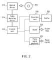
- FIG. 2 illustrates an exemplary video generation apparatus that generates scaled lines and pause signals in a video stream to a corresponding display apparatus.
- the exemplary video generation apparatus contains an optical device 212, a video decoding device 214, a control unit 216, a detection unit 218, a buffer 220, a scaler 222, and a pause signal generator 224.
- the optical device 212 is used for reading video information recorded on an optical disc 202.
- the video information is decoded by the video decoder device 214 to generate a video source.
- the optical device 212 may be replaced with a hard disk or any storage storing video information locally or remotely.
- a tiny portable MP4 player or a home media center server may produce the video source to be further processed by the components explained as follows.
- the video source is scaled by the scaler 222 to produce the scaled lines.
- the input line period length of the scaler 222 receiving the video source is the same as the output line period length of the scaler 222 supplying the video stream to the display apparatus.
- the video source has more scan lines for each frame than the video stream does, there are a number of output line periods of the scaler in which no valid scaled line are generated. In other words, valid scaled lines generated for each frame is less than a total number of output line periods for each frame of the video stream.
- the pause signals are therefore generated to inform the display apparatus when to pause rendering the video stream because the video stream does not always contain necessary valid scaled lines in every output line period.
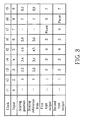
- FIG. 3 illustrates an example for performing a 6:5 scaling, which means 6 scan lines are scaled into corresponding 5 scan lines, such as the frame 16 being scaled into the frame 18 as shown in FIG. 1 .
- FIG. 2 and FIG. 3 are used together for explaining when the pause signals are generated along with the scaling process.
- a first scan line "1" of the video source arrives in the buffer 220.
- the first scan line “1” stored in the buffer 220 is directly output as corresponding scaled line "1".
- a second scan line “2” arrives in the buffer 220 in clock “t2”.
- a third scan line “3” also arrives in the buffer 220.
- the scaling position determines corresponding weightings of scaling reference lines "2” and "3”.
- Various scaling algorithms may be used for scaling.
- multiplying 0.8 to the scaling reference line “2" and multiplying 0.2 to the scaling reference line “3" before adding the multiplied results is an easy way to generate the scaled line "2".
- more than two scaling reference lines as well as other scaling algorithms may also be used for generating a scaled line.
- control unit 216 may record a preset scheme in advance.
- the preset scheme defines when to output a pause signal. For example, in the 6:5 scaling example illustrated above, a pause signal should be generated per 7 clocks.
- a detection unit 218 may be installed for detecting the buffer 220 to check whether associated scaling reference lines all arrive in the buffer 220. If there is one or more than one scale reference lines have not arrived to the buffer 220 yet, the pause signal generator 224 may be triggered to output a pause signal.
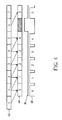
- FIG. 4 is a diagram illustrating dependency relationship between input scan lines 42 of a video source and output scan lines 44 of a video stream as well as pause signals 46 and display apparatus enabling signals 48.
- FIG. 4 it is also a 6:5 scaling.
- an input scan line "6" is used as the scaling reference line for generating output scan line "5", a pause signal 46 is therefore generated that causes the display apparatus that receives the pause signal 46 to disable for a clock in the display enabling signals 48.
- the above example can be used for a 576 lines to 480 lines scaling.
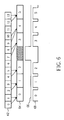
- FIG. 5 and FIG. 6 illustrate two schemes in an interlaced mode scaling.
- pause signals usually need to be produced more frequently in the interlaced mode scaling, because an image frame is divided into two field frames.
- FIG. 5 illustrates the relationship between the input scan lines 52 and the output scan lines 54. In the periods when the input scan lines "7" and "12" arrive, pause signals 56 are generated separately, which consequently cause a corresponding display apparatus to disable rendering a received video stream by setting video enabling signals 58.
- FIG. 6 illustrates another scheme of generation of pause signals 66 and corresponding display enabling signals 68 of a display apparatus. In this scheme, two pause signals 66 are generated together, instead of being generated separately in FIG. 5 , for waiting long enough for 13 input scan lines 62.
- a display apparatus receives pause signals for determining when to pause rendering a received video stream. With knowledge of which output line periods do not contain valid scaled lines for each frame, however, the pause signals may even be skipped. Once a display apparatus knows the preset scheme defining when valid scaled lines exist, the display apparatus may stop rendering the input stream in proper output line periods. If the display apparatus knows when to the pause rendering, a corresponding video generation apparatus may also reduce associated pause signal generator.
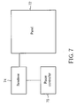
- FIG. 7 illustrates a display apparatus that knows the preset scheme that is used by a corresponding video generation apparatus.
- the display apparatus has a panel 72, a renderer 74, and a pause controller 76.
- the renderer 74 renders a video stream on the panel 72.
- the pause controller 76 controls the renderer 74 to pause rendering in a number of scan line periods for each frame of the video stream based on a preset scheme.
- the preset scheme is also used by a corresponding video generation apparatus for defining the number of scan line periods in each frame when a valid scan line is available or not available.
- Such display apparatus can use an interlaced mode panel or a progressive mode panel.
- a video source in the video generation apparatus has more scan lines in each frame than the video stream does.
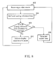
- FIG. 8 illustrates a flowchart of a video generation method.
- a video source is received (step 802), e.g. from an optical disc or decoded from an Internet video server.
- Scaling reference lines of the video source are stored in a buffer (step 804) so as to be used in scaling operation. It is then determined whether all necessary scaling reference lines are already buffered (step 806). If necessary scaling reference lines are already in the buffer, scaled lines are generated (step 808). Otherwise, a display apparatus is informed to pause rendering a video stream that contain the scaled lines (step 810).
- the output line period length to be used in the video stream and the input period length to receive the video source are the same, so that valid scaled lines generated for each frame is less than a total number of output line periods for each frame of the video stream.
- the "video generation apparatus” may refer to contain even only a scaler which contains a portion of buffer inside the scaler and another portion of buffer outside the scaler.
- the “buffer” may be distributed in several storage units. For example, when a line just arrives from the video source, the total line may be stored or only a current pixel necessary for scaling is stored. For an input line that needs not be scaled, the input line may be output directly without any scaling operation.
- the components mentioned above, such like “buffer”, “scaler”, “detection unit”, “control unit” and “pause signal generator” may be implemented totally in hardware circuits or be implemented with any types of hardware and software combination. General purpose processors may be used or specific circuits may be designed for achieving the function of scaling, buffer detection, pause signal generation, etc.
Landscapes
- Engineering & Computer Science (AREA)
- Physics & Mathematics (AREA)
- Computer Hardware Design (AREA)
- General Physics & Mathematics (AREA)
- Theoretical Computer Science (AREA)
- Controls And Circuits For Display Device (AREA)
- Television Systems (AREA)
Abstract
Description
- The present invention relates to a video generation apparatus, a display apparatus and a video generation method for scaling processing in video processing according to the pre-characterizing clauses of
claims - Format conversion is usually necessary when two machines need to cooperate. When a movie is to be played on a television with a DVD player, no matter what resolution of video is defined by an optical disc, the DVD player needs to generate a video output with a format consistent with resolution requirements of the television. For example, a video source with images of 576 resolution lines needs to be either discarded 96 lines or scaled to fit in a display apparatus that can only display 480 resolution lines. Discarding lines directly causes poor quality, but scaling brings higher cost and complexity of design.
- Therefore, it is desirable to design a video generation apparatus and corresponding display apparatus providing better image quality while reducing design complexity and cost.
- This in mind, the present invention aims at providing a video generation apparatus for processing a video source to generate a video stream supplied to a display apparatus, a video generation method, and a related display apparatus.
- This is achieved by a video generation apparatus, a video generation method and a related display apparatus according to
claims - As will be seen more clearly from the detailed descriptions following below, the claimed video generation apparatus for processing a video source to generate a video stream supplied to a display apparatus includes a buffer and a scaler. The buffer is capable of storing scaling reference lines retrieved from the video source. The scaler is used for generating scaled lines based on the scaling reference lines stored in the buffer, wherein the scaled lines are used in the video stream supplied to the display apparatus, and an input line period length of the scaler receiving the video source and an output line period length of the scaler supplying the video stream to the display apparatus are the same. Valid scaled lines generated for each frame by the scaler is less than a total number of output line periods for each frame of the video stream.
- In addition, as will be seen more clearly from the detailed descriptions following below, the claimed video generation method includes the steps of receiving a video source with an input line period length; buffering scaling reference lines retrieved from the video source; generating scaled lines based on the buffered scaling reference lines; and outputting scaled lines with an output line period length to be used in a video stream, wherein the input line period length and the output line period length are the same, and valid scaled lines generated for each frame is less than a total number of output line periods for each frame of the video stream.
- In addition, as will be seen more clearly from the detailed descriptions following below, the claimed display apparatus for receiving a video stream generated by a video generation apparatus includes a panel, a renderer, and a pause controller. The renderer is used for rendering the video stream to be displayed on the panel. The pause controller is used for controlling the renderer to pause rendering in a number of scan line periods for each frame of the video stream based on a preset scheme, wherein the preset scheme is also used by the video generation apparatus for defining the number of scan line period in each frame when valid scan line is not available.
- In the following, the invention is further illustrated by way of example, tacking reference to the accompanying drawings. Thereof
-
FIG. 1 illustrates an application based on the invention; -
FIG. 2 illustrates an exemplary video generation apparatus; -
FIG. 3 illustrates two schemes for scaling and generating pause signals; -
FIG. 4 illustrates a timing diagram example; -
FIG. 5 illustrates another timing diagram example; -
FIG. 6 illustrates yet another timing diagram example; -
FIG. 7 illustrates a display apparatus that contains the preset scheme inside; and -
FIG. 8 illustrates a flowchart of a method for scaling. - Certain terms are used throughout the description and following claims to refer to particular components. As one skilled in the art will appreciate, electronic equipment manufacturers may refer to a component by different names. This document does not intend to distinguish between components that differ in name but not function. In the following description and in the claims, the terms "include" and "comprise" are used in an open-ended fashion, and thus should be interpreted to mean "include, but not limited to ...". Also, the term "couple" is intended to mean either an indirect or direct electrical connection. Accordingly, if one device is coupled to another device, that connection may be through a direct electrical connection, or through an indirect electrical connection via other devices and connections.
-
FIG. 1 is a diagram illustrating an application according to the invention. Avideo generation apparatus 12, e.g. a DVD player, supplies a video stream to adisplay apparatus 14, e.g. a television. The video stream is generated by scaling a video source. Eachframe 16 in the video source has more scan lines than eachframe 1 8 does in the video stream. For example, there are six scan lines in theframe 16 illustrating a smiling face, but there are only five scan lines in thefame 18 illustrating the smiling face. Instead of skipping one line while rendering the smiling face in thedisplay apparatus 14, the video source is scaled by thevideo generation apparatus 12 while generating the video stream supplied to thedisplay apparatus 14. -
FIG. 2 illustrates an exemplary video generation apparatus that generates scaled lines and pause signals in a video stream to a corresponding display apparatus. The exemplary video generation apparatus contains anoptical device 212, avideo decoding device 214, acontrol unit 216, adetection unit 218, abuffer 220, ascaler 222, and apause signal generator 224. Theoptical device 212 is used for reading video information recorded on anoptical disc 202. The video information is decoded by thevideo decoder device 214 to generate a video source. Alternatively, theoptical device 212 may be replaced with a hard disk or any storage storing video information locally or remotely. For example, a tiny portable MP4 player or a home media center server may produce the video source to be further processed by the components explained as follows. - The video source is scaled by the
scaler 222 to produce the scaled lines. To simply the design of the scaler, which consequently reduces total cost and complexity of the video generation apparatus design, the input line period length of thescaler 222 receiving the video source is the same as the output line period length of thescaler 222 supplying the video stream to the display apparatus. When the video source has more scan lines for each frame than the video stream does, there are a number of output line periods of the scaler in which no valid scaled line are generated. In other words, valid scaled lines generated for each frame is less than a total number of output line periods for each frame of the video stream. The pause signals are therefore generated to inform the display apparatus when to pause rendering the video stream because the video stream does not always contain necessary valid scaled lines in every output line period. -
FIG. 3 illustrates an example for performing a 6:5 scaling, which means 6 scan lines are scaled into corresponding 5 scan lines, such as theframe 16 being scaled into theframe 18 as shown inFIG. 1 . In the following,FIG. 2 andFIG. 3 are used together for explaining when the pause signals are generated along with the scaling process. - In clock "t1", a first scan line "1" of the video source arrives in the
buffer 220. In clock "t2", the first scan line "1" stored in thebuffer 220 is directly output as corresponding scaled line "1". In addition, a second scan line "2" arrives in thebuffer 220 in clock "t2". In clock "t3", a third scan line "3" also arrives in thebuffer 220. The scaled line "2", which needs to reference two scaling reference lines, scan lines "2" and "3", now can be generated. Besides, since the scaled line "2" is supposed to appear at the scaling position "2.2", the scaling position determines corresponding weightings of scaling reference lines "2" and "3". Various scaling algorithms may be used for scaling. For example, multiplying 0.8 to the scaling reference line "2" and multiplying 0.2 to the scaling reference line "3" before adding the multiplied results is an easy way to generate the scaled line "2". To achieve better scaling result, more than two scaling reference lines as well as other scaling algorithms may also be used for generating a scaled line. - Then, in clocks "t4", "t5" and"t6", the
scaler 222 continues to generate scaled lines "3", "4" and "5" respectively. In clock "t7", the scaled line "6" may be generated because necessary scaling reference line "7" has arrived. In clock "t9", however, the next scaled line "7" needs to reference to scaling reference lines "8, 9" but the scaling reference line "9" has not arrived in clock "t9". In other words, in 6:5 scaling, a clock needs to be waited for each 7 lines. Therefore, a pause signal is generated by thepause signal generator 224 either in clock "t7" or in clock "t8", i.e. the two schemes of "First Type Output" and "Second Type Output" illustrated inFIG. 3 . - In actual designs, the
control unit 216 may record a preset scheme in advance. The preset scheme defines when to output a pause signal.
For example, in the 6:5 scaling example illustrated above, a pause signal should be generated per 7 clocks. Alternatively, adetection unit 218 may be installed for detecting thebuffer 220 to check whether associated scaling reference lines all arrive in thebuffer 220. If there is one or more than one scale reference lines have not arrived to thebuffer 220 yet, thepause signal generator 224 may be triggered to output a pause signal. -
FIG. 4 is a diagram illustrating dependency relationship betweeninput scan lines 42 of a video source andoutput scan lines 44 of a video stream as well as pause signals 46 and display apparatus enabling signals 48. InFIG. 4 , it is also a 6:5 scaling. In this example, an input scan line "6" is used as the scaling reference line for generating output scan line "5", apause signal 46 is therefore generated that causes the display apparatus that receives thepause signal 46 to disable for a clock in the display enabling signals 48. The above example can be used for a 576 lines to 480 lines scaling. -
FIG. 5 andFIG. 6 illustrate two schemes in an interlaced mode scaling. In contrast with progressive mode interlacing as explained above, pause signals usually need to be produced more frequently in the interlaced mode scaling, because an image frame is divided into two field frames.FIG. 5 illustrates the relationship between theinput scan lines 52 and theoutput scan lines 54. In the periods when the input scan lines "7" and "12" arrive, pause signals 56 are generated separately, which consequently cause a corresponding display apparatus to disable rendering a received video stream by setting video enabling signals 58.
Similarly,FIG. 6 illustrates another scheme of generation of pause signals 66 and corresponding display enabling signals 68 of a display apparatus. In this scheme, twopause signals 66 are generated together, instead of being generated separately inFIG. 5 , for waiting long enough for 13input scan lines 62. - In the above examples, a display apparatus receives pause signals for determining when to pause rendering a received video stream.
With knowledge of which output line periods do not contain valid scaled lines for each frame, however, the pause signals may even be skipped.
Once a display apparatus knows the preset scheme defining when valid scaled lines exist, the display apparatus may stop rendering the input stream in proper output line periods. If the display apparatus knows when to the pause rendering, a corresponding video generation apparatus may also reduce associated pause signal generator. -
FIG. 7 illustrates a display apparatus that knows the preset scheme that is used by a corresponding video generation apparatus. The display apparatus has apanel 72, arenderer 74, and apause controller 76.
Therenderer 74 renders a video stream on thepanel 72. Thepause controller 76 controls therenderer 74 to pause rendering in a number of scan line periods for each frame of the video stream based on a preset scheme. The preset scheme is also used by a corresponding video generation apparatus for defining the number of scan line periods in each frame when a valid scan line is available or not available. Such display apparatus can use an interlaced mode panel or a progressive mode panel. Besides, a video source in the video generation apparatus has more scan lines in each frame than the video stream does. -
FIG. 8 illustrates a flowchart of a video generation method. First, a video source is received (step 802), e.g. from an optical disc or decoded from an Internet video server. Scaling reference lines of the video source are stored in a buffer (step 804) so as to be used in scaling operation. It is then determined whether all necessary scaling reference lines are already buffered (step 806). If necessary scaling reference lines are already in the buffer, scaled lines are generated (step 808). Otherwise, a display apparatus is informed to pause rendering a video stream that contain the scaled lines (step 810). The output line period length to be used in the video stream and the input period length to receive the video source are the same, so that valid scaled lines generated for each frame is less than a total number of output line periods for each frame of the video stream. - The examples explained above may reduce the design complexity and consequently reduce cost of the whole system when the input line period length of a scaler is the same as output line period length of the scaler.
- Besides, the "video generation apparatus" may refer to contain even only a scaler which contains a portion of buffer inside the scaler and another portion of buffer outside the scaler. When the term "buffer" is used, the "buffer" may be distributed in several storage units. For example, when a line just arrives from the video source, the total line may be stored or only a current pixel necessary for scaling is stored. For an input line that needs not be scaled, the input line may be output directly without any scaling operation. Furthermore, the components mentioned above, such like "buffer", "scaler", "detection unit", "control unit" and "pause signal generator" may be implemented totally in hardware circuits or be implemented with any types of hardware and software combination. General purpose processors may be used or specific circuits may be designed for achieving the function of scaling, buffer detection, pause signal generation, etc.
- All combinations and sub-combinations of above-described features also belong to the invention.
Claims (20)
- A video generation apparatus (12) for processing a video source to generate a video stream supplied to a display apparatus (14),
characterized by:a buffer (220), capable of storing scaling reference lines retrieved from the video source; anda scaler (222), for generating scaled lines based on the scaling reference lines stored in the buffer (220), wherein the scaled lines are used in the video stream supplied to the display apparatus (14), and an input line period length of the scaler (222) receiving the video source and an output line period length of the scaler (222) supplying the video stream to the display apparatus (14) are the same;wherein valid scaled lines generated for each frame by the scaler (222) is less than a total number of output line periods for each frame of the video stream. - The video generation apparatus (12) of claim 1, characterized by:a pause signal generator (224) for outputting pause signals to indicate the display apparatus (14) when to pause rendering the video stream in a number of output line periods for each frame of the video stream.
- The video generation apparatus (1 2) of claim 2, characterized in that the pause signal generator (224) outputs the pause signals when the scaler (222) is unable to generate the scaled lines because the associated scaling reference lines do not all arrive in the buffer (220) yet.
- The video generation apparatus (12) of claim 3, characterized by:a detection unit (218) coupled to the scaler (222) for detecting whether the associated scaling reference lines all arrive in the buffer (220).
- The video generation apparatus (12) of claim 2, characterized by:a control unit (216) coupled to the scaler (222) and the pause signal generator (224) for determining when to generate the scaled lines and when to output the pause signals based on a preset scheme.
- The video generation apparatus (12) of claim 2, characterized in that the video source has more scan lines in each frame than the video stream does.
- The video generation apparatus (12) of claim 6, characterized in that the video stream is of progressive scanning mode.
- The video generation apparatus (12) of claim 7, characterized in that the video source has 576 scan lines and the video stream has 480 scan lines for each frame.
- The video generation apparatus (12) of claim 6, characterized in that the video stream is of interlaced mode.
- The video generation apparatus (12) of claim 1, characterized by:a video decoding device (214) for generating the video source.
- The video generation apparatus (12) of claim 10, characterized by:an optical device (212) for reading video information from an optical disc (202) and for supplying the video information to the video decoding device (214) for generating the video source.
- A video generation method, comprising:receiving a video source with an input line period length;
characterized by:buffering scaling reference lines retrieved from the video source; generating scaled lines based on the buffered scaling reference lines;
andoutputting scaled lines with an output line period length to be used in a video stream, wherein the input line period length and the output line period length are the same, and valid scaled lines generated for each frame is less than a total number of output line periods for each frame of the video stream. - The video generation method of claim 12, characterized by:generating pause signals to inform a display apparatus (14) when to pause rendering the video stream in a number of output line periods for each frame.
- The video generation method of claim 13, characterized in that the pause signals are generated when the associated scaling reference lines do not all arrive in a buffer (220) yet.
- The video generation method of claim 12, characterized in that the video source has more scan lines in each frame than the video stream does.
- The video generation method of claim 12, characterized by reading an optical disc (202) for retrieving and decoding video information to construct the video source.
- A display apparatus (14) for receiving a video stream generated by a video generation apparatus (12), the display apparatus (14) comprising:a panel (72);characterized by:a renderer (74), for rendering the video stream to be displayed on the panel (72); anda pause controller (76), for controlling the renderer (74) to pause rendering in a number of scan line periods for each frame of the video stream based on a preset scheme, wherein the preset scheme is also used by the video generation apparatus (12) for defining the number of scan line period in each frame when valid scan line is not available.
- The display apparatus (14) of claim 17, characterized in that the panel (72) is a progressive mode display device.
- The display apparatus (14) of claim 17, characterized in that the panel (72) is an interlaced mode display device.
- The display apparatus (14) of claim 17, characterized in that the video source has more scan lines in each frame than the video stream does.
Applications Claiming Priority (1)
| Application Number | Priority Date | Filing Date | Title |
|---|---|---|---|
| US12/351,864 US20100178037A1 (en) | 2009-01-12 | 2009-01-12 | Display apparatus, video generation apparatus, and method thereof |
Publications (2)
| Publication Number | Publication Date |
|---|---|
| EP2207161A2 true EP2207161A2 (en) | 2010-07-14 |
| EP2207161A3 EP2207161A3 (en) | 2011-04-13 |
Family
ID=42131390
Family Applications (1)
| Application Number | Title | Priority Date | Filing Date |
|---|---|---|---|
| EP09003018A Withdrawn EP2207161A3 (en) | 2009-01-12 | 2009-03-03 | Display apparatus, video generation apparatus, and method thereof |
Country Status (4)
| Country | Link |
|---|---|
| US (1) | US20100178037A1 (en) |
| EP (1) | EP2207161A3 (en) |
| CN (1) | CN101778272B (en) |
| TW (1) | TWI389561B (en) |
Families Citing this family (8)
| Publication number | Priority date | Publication date | Assignee | Title |
|---|---|---|---|---|
| CN104717484B (en) * | 2010-11-26 | 2017-06-09 | 联发科技(新加坡)私人有限公司 | Carry out method, video processing circuits and the video display system of video display control |
| US8707855B2 (en) | 2011-05-09 | 2014-04-29 | Eko Brands, Llc | Beverage Brewing Device |
| SG11201805570WA (en) | 2015-12-30 | 2018-07-30 | Corium Int Inc | Systems and methods for long term transdermal administration |
| WO2017223402A1 (en) | 2016-06-23 | 2017-12-28 | Corium International, Inc. | Adhesive matrix with hydrophilic and hydrophobic domains and a therapeutic agent |
| AU2017301928B2 (en) | 2016-07-27 | 2023-04-06 | Corium, LLC. | Donepezil transdermal delivery system |
| CA3031944A1 (en) | 2016-07-27 | 2018-02-01 | Corium International, Inc. | Transdermal delivery systems with pharmacokinetics bioequivalent to oral delivery |
| US10945968B2 (en) | 2016-07-27 | 2021-03-16 | Corium, Inc. | Memantine transdermal delivery systems |
| US11173132B2 (en) | 2017-12-20 | 2021-11-16 | Corium, Inc. | Transdermal adhesive composition comprising a volatile liquid therapeutic agent having low melting point |
Family Cites Families (7)
| Publication number | Priority date | Publication date | Assignee | Title |
|---|---|---|---|---|
| US5301031A (en) * | 1990-01-23 | 1994-04-05 | Hitachi Ltd. | Scanning conversion display apparatus |
| US6259479B1 (en) * | 1997-09-17 | 2001-07-10 | Sony Corporation | Letterbox filter apparatus and method |
| US6281873B1 (en) * | 1997-10-09 | 2001-08-28 | Fairchild Semiconductor Corporation | Video line rate vertical scaler |
| US7091944B2 (en) * | 2002-11-03 | 2006-08-15 | Lsi Logic Corporation | Display controller |
| CN101385070A (en) * | 2005-09-20 | 2009-03-11 | Nxp股份有限公司 | Apparatus and method for maintaining resampling or reformatting of video stream with respect to frame rate |
| US20070252902A1 (en) * | 2006-04-28 | 2007-11-01 | Mediatek Inc. | Teletext data slicer and method thereof |
| US20080100740A1 (en) * | 2006-10-27 | 2008-05-01 | Mediatek Inc. | Methods and apparatuses for adjusting digital video signals |
-
2009
- 2009-01-12 US US12/351,864 patent/US20100178037A1/en not_active Abandoned
- 2009-03-03 EP EP09003018A patent/EP2207161A3/en not_active Withdrawn
- 2009-11-03 CN CN2009102104930A patent/CN101778272B/en active Active
- 2009-11-03 TW TW098137229A patent/TWI389561B/en not_active IP Right Cessation
Also Published As
| Publication number | Publication date |
|---|---|
| US20100178037A1 (en) | 2010-07-15 |
| CN101778272B (en) | 2011-11-02 |
| CN101778272A (en) | 2010-07-14 |
| EP2207161A3 (en) | 2011-04-13 |
| TWI389561B (en) | 2013-03-11 |
| TW201027986A (en) | 2010-07-16 |
Similar Documents
| Publication | Publication Date | Title |
|---|---|---|
| US20100178037A1 (en) | Display apparatus, video generation apparatus, and method thereof | |
| JP2005027068A (en) | Video signal converting apparatus and method therefor | |
| US6674480B2 (en) | Device for and method of converting a frame rate in a moving picture decoder, and a record medium and an integrated circuit device for implementing such a method | |
| US8244112B2 (en) | Video processing apparatus and controlling method for same | |
| JPWO2004107746A1 (en) | Digital interface decoding receiver | |
| KR20040041681A (en) | Trick modes using non-progressive dummy bidirectional predictive pictures | |
| JP4712195B2 (en) | Method and apparatus for down conversion of video data | |
| JP5025809B1 (en) | Video processing apparatus and video processing method | |
| JP2009296081A (en) | Video image reproducer | |
| CN113055744A (en) | Video decoding method and device | |
| US20110064391A1 (en) | Video-audio playback apparatus | |
| JP2005045787A (en) | Video signal processing apparatus to generate both progressive and interlace video signals | |
| KR100671985B1 (en) | How to Process Sequential Video Signals in Digital TV Receivers | |
| CN101605221B (en) | Video signal display system, display method and video signal reproducing device | |
| US8031266B2 (en) | Method and apparatus for video decoding and de-interlacing | |
| JP2008009182A (en) | Liquid crystal display | |
| US20070122045A1 (en) | System for scaling a picture unit from a first video resolution format to a second video resolution format | |
| CN1913616A (en) | Method and apparatus for processing video signal | |
| US8184687B1 (en) | System and method for generating a mosaic image stream | |
| US8768150B2 (en) | Method and system for trick mode support in a motion adaptive deinterlacer with inverse telecine | |
| JP3601330B2 (en) | Video signal playback device | |
| US8681269B2 (en) | Video reproduction apparatus and video reproducing method | |
| EP1990803A1 (en) | Method of high speed video playback and video playback apparatus using the same | |
| JP2006005594A (en) | Video data reproducing apparatus and video data reproducing method | |
| EP1936958A1 (en) | A device for capturing images and a control method thereof |
Legal Events
| Date | Code | Title | Description |
|---|---|---|---|
| PUAI | Public reference made under article 153(3) epc to a published international application that has entered the european phase |
Free format text: ORIGINAL CODE: 0009012 |
|
| AK | Designated contracting states |
Kind code of ref document: A2 Designated state(s): AT BE BG CH CY CZ DE DK EE ES FI FR GB GR HR HU IE IS IT LI LT LU LV MC MK MT NL NO PL PT RO SE SI SK TR |
|
| AX | Request for extension of the european patent |
Extension state: AL BA RS |
|
| PUAL | Search report despatched |
Free format text: ORIGINAL CODE: 0009013 |
|
| AK | Designated contracting states |
Kind code of ref document: A3 Designated state(s): AT BE BG CH CY CZ DE DK EE ES FI FR GB GR HR HU IE IS IT LI LT LU LV MC MK MT NL NO PL PT RO SE SI SK TR |
|
| AX | Request for extension of the european patent |
Extension state: AL BA RS |
|
| RIC1 | Information provided on ipc code assigned before grant |
Ipc: H04N 7/01 20060101ALI20110310BHEP Ipc: G06T 3/40 20060101ALI20110310BHEP Ipc: G09G 5/00 20060101AFI20100512BHEP |
|
| AKY | No designation fees paid | ||
| REG | Reference to a national code |
Ref country code: DE Ref legal event code: R108 |
|
| REG | Reference to a national code |
Ref country code: DE Ref legal event code: R108 Effective date: 20111221 |
|
| STAA | Information on the status of an ep patent application or granted ep patent |
Free format text: STATUS: THE APPLICATION IS DEEMED TO BE WITHDRAWN |
|
| 18D | Application deemed to be withdrawn |
Effective date: 20111014 |