EP2206567A1 - Press mold for sheet metal forming, method of treating press mold surface, and process for manufacturing automobile body - Google Patents
Press mold for sheet metal forming, method of treating press mold surface, and process for manufacturing automobile body Download PDFInfo
- Publication number
- EP2206567A1 EP2206567A1 EP08792276A EP08792276A EP2206567A1 EP 2206567 A1 EP2206567 A1 EP 2206567A1 EP 08792276 A EP08792276 A EP 08792276A EP 08792276 A EP08792276 A EP 08792276A EP 2206567 A1 EP2206567 A1 EP 2206567A1
- Authority
- EP
- European Patent Office
- Prior art keywords
- die
- press die
- sheet metal
- press
- metal forming
- Prior art date
- Legal status (The legal status is an assumption and is not a legal conclusion. Google has not performed a legal analysis and makes no representation as to the accuracy of the status listed.)
- Granted
Links
Images




Classifications
-
- B—PERFORMING OPERATIONS; TRANSPORTING
- B21—MECHANICAL METAL-WORKING WITHOUT ESSENTIALLY REMOVING MATERIAL; PUNCHING METAL
- B21D—WORKING OR PROCESSING OF SHEET METAL OR METAL TUBES, RODS OR PROFILES WITHOUT ESSENTIALLY REMOVING MATERIAL; PUNCHING METAL
- B21D37/00—Tools as parts of machines covered by this subclass
- B21D37/20—Making tools by operations not covered by a single other subclass
-
- B—PERFORMING OPERATIONS; TRANSPORTING
- B24—GRINDING; POLISHING
- B24C—ABRASIVE OR RELATED BLASTING WITH PARTICULATE MATERIAL
- B24C1/00—Methods for use of abrasive blasting for producing particular effects; Use of auxiliary equipment in connection with such methods
-
- C—CHEMISTRY; METALLURGY
- C25—ELECTROLYTIC OR ELECTROPHORETIC PROCESSES; APPARATUS THEREFOR
- C25D—PROCESSES FOR THE ELECTROLYTIC OR ELECTROPHORETIC PRODUCTION OF COATINGS; ELECTROFORMING; APPARATUS THEREFOR
- C25D3/00—Electroplating: Baths therefor
- C25D3/02—Electroplating: Baths therefor from solutions
- C25D3/04—Electroplating: Baths therefor from solutions of chromium
-
- C—CHEMISTRY; METALLURGY
- C25—ELECTROLYTIC OR ELECTROPHORETIC PROCESSES; APPARATUS THEREFOR
- C25D—PROCESSES FOR THE ELECTROLYTIC OR ELECTROPHORETIC PRODUCTION OF COATINGS; ELECTROFORMING; APPARATUS THEREFOR
- C25D5/00—Electroplating characterised by the process; Pretreatment or after-treatment of workpieces
- C25D5/34—Pretreatment of metallic surfaces to be electroplated
-
- C—CHEMISTRY; METALLURGY
- C25—ELECTROLYTIC OR ELECTROPHORETIC PROCESSES; APPARATUS THEREFOR
- C25D—PROCESSES FOR THE ELECTROLYTIC OR ELECTROPHORETIC PRODUCTION OF COATINGS; ELECTROFORMING; APPARATUS THEREFOR
- C25D5/00—Electroplating characterised by the process; Pretreatment or after-treatment of workpieces
- C25D5/48—After-treatment of electroplated surfaces
-
- C—CHEMISTRY; METALLURGY
- C25—ELECTROLYTIC OR ELECTROPHORETIC PROCESSES; APPARATUS THEREFOR
- C25D—PROCESSES FOR THE ELECTROLYTIC OR ELECTROPHORETIC PRODUCTION OF COATINGS; ELECTROFORMING; APPARATUS THEREFOR
- C25D5/00—Electroplating characterised by the process; Pretreatment or after-treatment of workpieces
- C25D5/48—After-treatment of electroplated surfaces
- C25D5/52—After-treatment of electroplated surfaces by brightening or burnishing
-
- C—CHEMISTRY; METALLURGY
- C25—ELECTROLYTIC OR ELECTROPHORETIC PROCESSES; APPARATUS THEREFOR
- C25D—PROCESSES FOR THE ELECTROLYTIC OR ELECTROPHORETIC PRODUCTION OF COATINGS; ELECTROFORMING; APPARATUS THEREFOR
- C25D5/00—Electroplating characterised by the process; Pretreatment or after-treatment of workpieces
- C25D5/60—Electroplating characterised by the structure or texture of the layers
- C25D5/605—Surface topography of the layers, e.g. rough, dendritic or nodular layers
-
- C—CHEMISTRY; METALLURGY
- C25—ELECTROLYTIC OR ELECTROPHORETIC PROCESSES; APPARATUS THEREFOR
- C25D—PROCESSES FOR THE ELECTROLYTIC OR ELECTROPHORETIC PRODUCTION OF COATINGS; ELECTROFORMING; APPARATUS THEREFOR
- C25D5/00—Electroplating characterised by the process; Pretreatment or after-treatment of workpieces
- C25D5/67—Electroplating to repair workpiece
Definitions
- the present invention relates to a press die for sheet metal forming, a processing method of a surface of the press die, and a manufacturing method of a vehicle body.
- forming of outer panel components of an automobile and the like have been carried out by press forming, in which a work is press processed using a press die.
- a press die used in a press process be such that the die surface, which is a contact surface with a work in the press die, be smoothed. By smoothing the die surface, it is possible to increase surface precision of a work (outer panel components) formed.
- Patent Document 1 As a method for smoothing a die surface, the applicant proposes a processing method of a die surface and a die for which the processing method has been applied (see Patent Document 1) in which, first, a forming surface of a die is formed by a cutting process, then a synthetic resin is applied to the formed die surface, and next shot blasting is performed for smoothing a shape of the die surface.
- Patent Document 1 by a cutting process, it is possible effectively to grind high spots that are leftover from cutting generated on a die surface, thereby efficiently carrying out smoothing of a die surface.
- the present invention has the objective of providing a press die for sheet metal forming, a processing method of a surface of the press die, and a manufacturing method of a vehicle body, capable of maintaining a high rate of non-defective works after a press process.
- a press die for sheet metal forming has a multitude of concave portions in a die surface, in which a roughness (Ry) of the die surface is 30 to 38 ⁇ m.
- the press die for sheet metal forming as described in the first aspect has a plated layer on the die surface.
- the plated layer has a thickness of 5 to 30 ⁇ m.
- the plated layer is formed by electroplating.
- the electroplating is chrome plating.
- a roughness (Ry) of the die surface is 30 to 38 ⁇ m.
- a shot blast process is performed on the surface of the press die, forming a multitude of concave portions, and then a polishing process is performed on the surface of the press die to which a shot blast process was performed, to make a roughness (Ry) on the surface of the press die be 30 to 38 ⁇ m.
- a press die has had surfacing processing performed by way of the processing method of the surface of the press die for sheet metal forming as described in the seventh or eighth aspect.
- a maintenance method of the die surface in the press die for sheet metal forming as described in any one of the second to sixth aspects includes: a step of removing the plated layer, a step of forming a new plated layer on the die surface from which the plated layer was removed, a step of forming a multitude of concave and convex portions by performing a shot blast process on the new plated layer, and a step of performing polishing processing on the new plated layer on which the multitude of concave and convex portions has been formed, to make a roughness (Ry) of the die surface be 30 to 38 ⁇ m.
- a press die for sheet metal forming has a curved surface portion in which a die surface is formed of a curved surface and a substantially planar surface portion in which a die surface is formed of a substantially planar surface, in which a multitude of concave portions has been formed only on the die surface in the substantially planar surface portion.
- the die surface in the curved surface portion has a radius of curvature of no greater than 5 mm, and the die surface in the substantially planar surface portion has a radius of curvature of greater than 5 mm.
- a roughness (Ry) is 30 to 38 ⁇ m in the die surface of the substantially planar surface portion in which the multitude of concave portions has been formed.
- the die surface in the curved surface portion and the substantially planar surface portion has a plated layer.
- the plated layer has a thickness of 5 to 30 ⁇ m.
- the plated layer is formed by electroplating.
- the electroplating is chrome plating.
- a press die for sheet metal forming is characterized in that , in the press die for sheet metal forming including a three-dimensional die surface having a curved surface portion and a substantially planar surface portion, a shot blast process is performed on the substantially planar surface portion to exclude the curved surface portion, thereby forming a multitude of concave portions.
- a surface processing method of a press die for sheet metal forming has a curved surface portion in which the die surface is formed of a curved surface and a substantially planar surface portion in which the die surface is formed of a substantially planar surface, including a shot blast process step of forming a multitude of concave portions by performing a shot blast process on only the die surface in the substantially planar surface portion.
- the surface processing method for a press die for sheet metal forming as described in the nineteenth aspect includes a polishing process step of performing a polishing process on the die surface on which the multitude of concave portions has been formed in the shot blast process step, after the shot blast process step.
- the surface processing method of a press die for sheet metal forming as described in the twentieth aspect is characterized in that in the polishing process step, a roughness (Ry) in the die surface of the substantially planar surface portion in which the multitude of concave portions has been formed has been adjusted to be 30 to 38 ⁇ m.
- the surface processing method of a press die for sheet metal forming as described in the twentieth or twenty-first aspect includes, before the shot blast process step, a masking step of performing masking processing on at least the die surface in the curved surface portion.
- the processing method of a surface of a press die for sheet metal forming as described in the twenty-second aspect includes, before the masking step, a plating step of performing plating processing on a surface of the press die.
- a press die for sheet metal forming has had surface processing performed thereto by a processing method of a press die surface for sheet metal forming as described in any one of the nineteenth to twenty-third aspects.
- a maintenance method of a die surface in a press die for metal includes a plated layer removal step of removing the plated layer; a re-plating step of forming a new plated layer on the die surface in the curved surface portion and the substantially planar surface portion from which the plated layer was removed in the plated layer removal step; a masking step of performing masking processing at least on the die surface of the curved surface portion in the new plated layer formed in the re-plating step; a shot blast process step of, after the masking step, performing a shot blast process on at least one portion on the die surface of the substantially planar surface portion, thereby forming a multitude of concave and convex portions; and a polishing process step of performing a polishing process on the new plated layer on the die surface on which the multitude of concave and convex portions has been formed.
- a manufacturing method of a vehicle body includes a forming step of forming outer panel components of a vehicle body using a press die for sheet metal forming as described in any one of the first to sixth aspects and the eleventh to eighteenth aspects, and a welding step of welding at least one outer panel component formed in the forming step, thereby constructing an entirety of a vehicle body.
- a manufacturing method of industrial products includes a step of manufacturing a work by forming a sheet member using a press die for sheet metal forming as described in any of the first to sixth and eleventh to eighteenth aspects, and a welding step of manufacturing major components of industrial goods by welding a plurality of the work.
- a processing method of a press die for sheet metal forming and a press die surface of the present invention since a die surface has a multitude of concave portions of prescribed depth, even in a case in which such foreign matter as iron dust and the like adhere to the die surface, large concave and convex portions are not formed on the work after a press process, and it is possible to maintain a high rate of non-defective works after the press process.
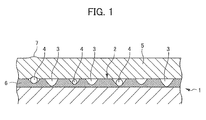
- FIG. 1 is a view illustrating a state of carrying out a press process using a press die for sheet metal forming of the present invention.
- a press die for sheet metal forming (hereafter referred to as just "press die” as well) 1 of the first embodiment, as illustrated in FIG. 1 has a multitude of concave portions 3 in a die surface 2. Furthermore, a roughness (Ry) of a die surface 2 on which this multitude of concave portions 3 has been formed is within a range of 30 to 38 ⁇ m.
- roughness in the present specification refers to "surface roughness” as stipulated in JIS B0601-1994, and "(Ry)" indicates a height from a lowest valley to a highest peak for each reference length: a maximum height.
- the roughness (Ry) of the die surface 2 in which the multitude of concave portions 3 is formed is set to within a range of 30 to 38 ⁇ m, it is possible to prevent a reduction in surface precision of a work 5 after a press process due to existence of the multitude of concave portions 3, while being able to prevent formation of large concave and convex portions on a surface of the work 5 after a press process, even in a case of adherence of relatively large-sized foreign matter 4.
- a height of concave and convex portions (hereafter referred to as "deformity 7" as well) formed on a surface of a work 5 after a press process can be limited to approximately 9 ⁇ m.
- a height of a deformity 7 formed on a surface of a work 5 after a press process can be limited to approximately 9 ⁇ m.
- a multitude of concave portions 3 is formed on a die surface 2, and a roughness (Ry) of the die surface 2 formed by this multitude of concave portions 3 is set to be 30 to 38 ⁇ m, it is possible to maintain a high rate of non-defective products, even when foreign matter 4 adheres onto the die surface 2.
- a roughness (Ry) of the die surface 2 is less than 30 ⁇ m
- a large deformity 7 is formed after a press process, and the rate of non-defective products of works 5 is lowered.
- a roughness (Ry) of the die surface 2 is greater than 38 ⁇ m, due to the presence of the multitude of concave portions 3 thus formed, surface precision of the works 5 after the press process is lowered.
- a method for forming a multitude of concave portions 3 on the die surface 2 for example, a method may be given in which, after performing a shot blast process to the die surface 2 and forming a multitude of concave and convex portions, a polishing process is performed to the die surface 2, and a roughness (Ry) of the die surface 2 in which the multitude of concave portions 3 has been formed is adjusted to be 30 to 38 ⁇ m (details to be described later).
- roller including a multitude of concave and convex portions of a prescribed depth in forming a multitude of concave portions 3 on the die surface 2 is also acceptable.
- a press die 1 having a plated layer is preferred.
- a plated layer 6 be formed on the die surface 2.
- strength of the die surface 2 is increased, increasing abrasion resistance of a press die 1.
- corrosion resistance of the press die 1 thereby lengthening a usable life of the press die 1.
- the plated layer 6 may be formed by electroplating such as industrial chrome plating, nickel-tungsten plating, dispersion nickel plating, or rhodium plating, or by such electroless plating as electroless nickel plating, and in particular, it is preferable, from a durability perspective, to form thereof by industrial chrome plating.
- a thickness of the plated layer 6, from a perspective of durability and reliability as an industrial plating, would preferably be 5 to 30 ⁇ m, and more preferably 15 to 25 ⁇ m.
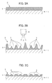
- FIGS. 2A to 2C are views illustrating each step in a processing method of a press die surface of a first embodiment.
- a processing method of a press die surface of a first embodiment includes 1) a plating processing step, 2) a shot blast process step, and 3) a polishing process step.
- plating processing is performed on a die surface 2, which is a contact surface with a work in a press die 1 (see FIG. 2A ).
- the plating processing for example, can be carried out by a processing method of industrial chrome plating, which is a common electroplating, and a plated layer 6 is formed on the die surface 2 by the plating method.
- press die 1 for example, it is possible to use such cast-iron dies as FC250, FC300, FCD500, and the like.
- a shot blast process is performed on the die surface 2 on which plating processing has been applied (see FIG. 2B ).
- a shot blast process By a shot blast process, a multitude of concave and convex portions is formed on the die surface.
- the shot blast process is carried out by spraying shot blasting media of a prescribed particle diameter from an injection device 8 onto a die surface 2 after the plating process.
- shot blasting media used in the shot blast process for example, it is possible to use glass beads, aluminum beads, ceramic beads, and the like.
- a particle diameter of shot blasting media, from a perspective of forming a concave portion 3 of preferable depth is preferably 0.1 to 0.3 mm.
- a shot blasting pressure in the shot blast process also from a perspective of forming a concave portion 3 of preferable depth, is preferably 0.5 to 1.2 MPa.
- a roughness (Ry) of a die surface 2 in which a multitude of concave portions 3 is formed after the shot blast process from a perspective of assuming a roughness (Ry) of the die surface 2 after a polishing step (after final finishing) to be described later to be 30 to 38 ⁇ m, is 35 to 43 ⁇ m.
- a polishing step after a shot blast process approximately 5 ⁇ m is planed from the overall die.
- a polishing process is performed to the die surface 2 on which a multitude of concave portions 3 has been formed by a shot blast process (see FIG. 2C ).
- a shape of a peak part of a convex portion formed between two concave portions 3 and 3 adjacent to each other is flattened, while a roughness (Ry) of the die surface 2 on which a multitude of concave portions 3 is formed is adjusted to be within a range of 30 to 38 ⁇ m.
- the polishing process can be carried out using a file or the like; for example, 600 to 800 grain sandpaper can be used.
- the die surface 2 it is preferable to finish the die surface 2 so that the roughness (Ry), which is a concave/convex average, is 35 ⁇ m.
- a processing method of a press die surface of the first embodiment since a multitude of concave portions 3 having prescribed depth is formed on the die surface 2, even in a case in which such foreign matter 4 as iron dust or the like become adhered onto the die surface 2, it is possible to obtain a press die 1 which can maintain a high non-defective product rate of works 5 after the press process.
- a processing method of a press die surface of the first embodiment since a die can have a plated layer by having a plating processing step, a multitude of concave portions is formed on a plated layer part of a die surface. Therefore, in a case in which a die is used repeatedly in a press process and a roughness (Ry) of a die surface becomes outside a range of 30 to 38 ⁇ m, it is possible to recover a roughness (Ry) of a die surface easily by removing a plated layer, and performing re-plating processing, a shot blast process, and a polishing process.
- a press die which has had surface processing applied by a processing method of a press die surface of the first embodiment, it is possible easily to carry out maintenance for preserving a roughness (Ry) of a die surface to within a prescribed range.
- a deterioration measurement of a roughness (Ry) of a die surface can easily be measured using a surface roughness measuring instrument to be described later.
- removal of a plated layer can be carried out, for example, by soaking a die having a plated layer in a solution such as acid or the like.
- Processing of a press die in a first embodiment can be performed to an entire surface of the die surface 2, but it is preferable to be performed especially on flat surfaces for which the presence of deformities 7 after a press process is easily visually recognized, that is, only to regions of a low degree of curvature at a time of a press process.
- Regions of a low degree of curvature can have deformities 7 after a press process easily recognized, but on the other hand, force applied to a the die surface 2 at a time of a press process is relatively small compared to regions of a high degree of curvature.
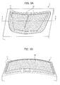
- FIGS. 3A and 3B are perspective views indicating a press die 1 of a second embodiment of the present invention, in which FIG. 3A illustrates a press die for a hood of an automobile, and FIG. 3B illustrates a press die for a roof panel of an automobile.
- FIG. 4 is a cross-sectional view taken along a line "X-X" of FIG. 3A .
- FIG. 5 is a view illustrating a state of carrying out a press process using a press die for sheet metal forming of the present invention.
- a press die 1 of the second embodiment is a press die for sheet metal forming (hereafter referred to as a "press die” as well) 1 having a curved surface portion 11 and a substantially planar surface portion 12, and is a press die 1 placed and used so that a die surface 2 faces upwards.
- a press die for sheet metal forming
- a sheet member of steel sheet or the like is placed on an upper side of the press die 1, a second press die (not illustrated) having a die surface of a shape corresponding to a shape of the die surface 2 on the press die 1 on an upper side of a sheet member is placed, and the sheet member is press-formed by moving the press die 1 and/or the press die 2 in a vertical direction.
- the curved surface portion 11 indicates a part formed by a curved surface in which a radius of curvature of the die surface 2 is no more than 5 mm
- the substantially planar surface portion 12 indicates a part formed by a substantially planar surface in which a radius of curvature of the die surface 2 is larger than 5 mm.
- the press die 1 of the second embodiment is formed with a multitude of concave portions 3 only on the die surface of the substantially planar surface portion 12. Furthermore, in the second embodiment, in a state in which a die 1 is positioned for a purpose of carrying out a press process, the substantially planar surface portion 12, as illustrated in FIG. 4 , has a horizontal area 12b and a sloped area 12a. In addition, a multitude of concave portions 3 is formed on a die surface 2 of the horizontal area 12b in the substantially planar surface portion 12.
- a multitude of concave portions 3 is not formed on a die surface 2 of the curved surface portion 11. Furthermore, a multitude of concave portions 3 is not formed in a vicinity of a border with the curved surface portion 11 in the substantially planar surface portion 12, and is not formed in a sloped area 12a in the substantially planar surface portion 12.
- a horizontal area 12b indicates an area to be placed in which, in the substantially planar surface portion 12, an inclination angle with respect to a horizontal surface of the substantially planar surface portion 12 is preferably less than 45 degrees, more preferably less than 30 degrees, and most preferably less than 20 degrees.
- a sloped area 12a indicates an area to be positioned so that an inclination angle with respect to a horizontal surface of the substantially planar surface portion 12 is preferably at least 45 degrees, more preferably at least 30 degrees, and most preferably at least 20 degrees.
- the press die 1 of the present invention having a multitude of concave portions 3 in a die surface 2 of a substantially planar surface portion 12, even in a case in which fine foreign matter 4 of iron dust and the like becomes caught in the die surface 2, because the foreign matter 4 enters concave portions 3, large concave and convex portions are not formed on a work 5 surface after a press process.
- a multitude of concave portions 3 is not formed on the curved surface portion 11, but is only formed on the substantially planar surface portion 12.
- Foreign matter 4 of iron dust and the like do not adhere easily to the curved surface portion 11 with a small radius of curvature (of a large curvature) on the press die 1, but adhere easily to the substantially planar surface portion 12 with a large radius of curvature (of a small curvature).
- foreign matter 4 of iron dust and the like generated at a time of press forming adheres relatively more on the substantially planar surface portion 12 than on the curved surface portion 11 on the press die 1. Therefore, by forming a multitude of concave portions 3 on only the substantially planar surface portion 12, it is possible effectively to prevent adverse effects to a work 5 surface by foreign matter 4 adhering to the die surface 2.
- a multitude of concave portions 3 is not formed on the curved surface portion 11 on the press die 1.
- a multitude of concave portions 3 is formed on a curved surface portion 11 of great curvature, there is a risk that scratches (abrasions) may form on a work surface due to the presence of the multitude of concave portions 3.
- a multitude of concave portions 3 is not formed on a sloped area 12a on a substantially planar surface portion 12, either.
- the die surface 2 is placed so as to be sloped, foreign matter 4 of iron dust and the like slide off the die surface 2 easily, so it is difficult for the foreign matter 4 to adhere to the die surface 2 on the sloped area 12a. Therefore, even in a case in which a multitude of concave portions 3 is not formed on a die surface 2 on a sloped area 12a, it is difficult for concave and convex portions to arise on a surface of a work 5 after a press process due to foreign matter 4 of iron dust and the like.
- a roughness (Ry) of a die surface 2 on a substantially planar surface portion 12 on which a multitude of concave portions 3 has been formed is set to be in the range of 30 to 38 ⁇ m.
- a roughness (Ry) of a substantially planar surface portion 12 on which a multitude of concave portions 3 has been formed to be in the range of 30 to 38 ⁇ m, it is possible to prevent a lowering of surface precision of a work 5 on the substantially planar surface portion 12 after a press process due to a presence of a multitude of concave portions 3, while it is possible to prevent formation of large concave and convex portions on a surface of a work 5 after a press process, even in a case in which foreign matter 4 of relatively large size adhere to the die surface 2.
- the press die 1, as illustrated in FIG. 5 preferably has a plated layer 6. Moreover, the effect is identical even when the present invention is applied to a die for which plating processing has not been performed.
- FIGS. 6A to 6D are views illustrating each step in a processing method of a press die surface of the second embodiment.
- the processing method of a press die surface of the second embodiment includes: 1) a plating processing step, 2) a masking step, 3) a shot blast process step, and 4) a polishing process step.
- plating processing is performed to a die surface 2, which is a contact surface with a work on a press die 1 (see FIG. 6A ).
- the plating processing is carried out with a method similar to that of the first embodiment.
- masking processing is performed to a curved surface portion 11 and a boundary area of a curved surface portion 11 and a substantially planar surface portion 12, on a die surface 2 to which plating processing has been performed (see FIG. 6B ).
- Masking processing for example, can be carried out by adhering a masking material 9 to a curved surface portion 11 and a boundary area of a curved surface portion 11 and a substantially planar surface portion 12, on the die surface 2.
- a masking material 9 aluminum tape, vinyl tape, or the like can be given.
- the masking process By performing the masking process, in a shot blast step to be described later, it is possible to prevent a multitude of concave portions 3 from being formed on the curved surface portion 11.
- the masking processing be performed to an area approximately 10 mm from the boundary of the curved portion 11 and the substantially planar surface portion 12 on the substantially planar surface portion 12.
- the masking processing in the present embodiment, is performed to the curved surface portion 11 and the boundary area of the curved surface portion 11 and the substantially planar surface portion 12, but performing at least to the curved surface portion 11 is acceptable.
- a shot blast process is performed with a similar method to that of the first embodiment (see FIG. 6C ).
- a shot blast process a multitude of concave and convex portions is formed on a substantially planar surface portion 12 on a die surface 2.
- a shot blast process is not performed to a sloped area 12a on the substantially planar surface portion 12, and a multitude of concave portions 3 is not formed on the die surface 2 on the sloped area 12a (see FIG. 4 ).
- shot blasting media is not uniformly sprayed on the sloped die surface 2, and there is a risk in that a depth of a multitude of concave portions 3 formed on the die surface 2 may be nonuniform.
- a roughness (Ry) of the die surface 2 on the substantially planar surface portion 12 on which a multitude of concave portions 3 has been formed after a shot blast process, from a perspective of setting a roughness (Ry) on a die surface 2 after a polishing process step (after final finishing) to be 30 to 38 ⁇ m, should preferably be 30 to 43 ⁇ m. In other words, in a polishing step after a shot blast process, approximately 5 ⁇ m of the surface is planed from the overall die.
- a polishing process is performed with a similar method to that of the first embodiment (see FIG. 6D ).
- the processing method of the press die surface of the second embodiment since a multitude of concave portions 3 having a prescribed depth is formed on the die surface 2 of the substantially planar surface portion 12 on the press die 1 having a curved surface portion 11 and a substantially planar surface portion 12, even in a case in which such foreign matter 4 as iron dust and the like adhere to the die surface 2, it is possible to obtain a press die 1 which can maintain a high non-defective product rate of works 5 after a press process.
- the press die since the press die has a plated layer by having a plating processing step, a multitude of concave portions is formed on the plated layer part on the die surface. Therefore, in a case in which a die is used repeatedly in a press process and a roughness (Ry) of a die surface becomes outside a range of 30 to 38 ⁇ m, it is possible easily to form again a multitude of concave portions only on a substantially planar surface portion on the press die by removing a plated layer, and performing re-plating processing, masking processing, a shot blast process, and a polishing process to recover a roughness (Ry) of the die surface.
- the shot blast process to the press die surface in the second embodiment is performed only to the flat substantially planar surface portion in which presence of deformities 7 after a press process is easily visually recognizable, that is to regions of shallow curvature at a time of a press process.
- Regions of shallow curvature are such that the presence of deformities 7 after a press process is easily visually recognized, while on the other hand, the force applied to the die surface 2 at a time of a press process is relatively small compared to regions of great curvature.
- the above-described press die to which the processing method of the second embodiment has been applied may preferably be used for forming components having curved surface portions and substantially planar surface portions, and in particular, for forming various outer panel components configuring a vehicle body and the like. Furthermore, an identical effect was obtained whether the outer panel component was iron or aluminum.
- FIG. 7 is a flow diagram illustrating an embodiment of a manufacturing method of a vehicle body of the present invention.
- FIG. 8 is a diagram illustrating an outline of a presetting step and a vehicle construction step in a manufacturing method of a vehicle body of the present invention.
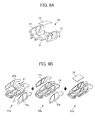
- FIG. 9A is a diagram illustrating an example of a vehicle body construction step in a manufacturing method of a vehicle body of the present invention.
- FIG. 9B is a diagram illustrating another example of a vehicle body construction step in a manufacturing method of a vehicle body of the present invention.
- the present embodiment is a manufacturing method of a vehicle body of the present invention applied to a manufacturing method of a vehicle body of an automobile.
- the present embodiment includes a forming step S2 of forming an outer panel component of a vehicle body using a press die of the present invention, and a welding step S3 of welding a plurality of outer panel components formed in the forming step.
- a manufacturing method of a vehicle body of an automobile of the present embodiment has a shearing step S1 of shearing a coil of sheet steel; a forming step S2 of forming a shape of various outer panel components configuring a vehicle body by a press die in which a steel sheet has been sheared in the shearing step S1; a welding step (hereinafter, also referred to as a "component welding step") S3 of manufacturing each component of a vehicle body by welding a plurality of types of various outer panel components formed in the forming step S2; a presetting step S4 of positioning each component formed in the component welding step S3 at a prescribed location; and a vehicle body construction step S5 of forming a vehicle body by constructing each component positioned at a prescribed location in the presetting step S4.
- a welding step S1 of shearing a coil of sheet steel
- a forming step S2 of forming a shape of various outer panel components configuring a vehicle body by a press die in which a steel
- a coil of sheet steel delivered to a vehicle body plant is cut off into a prescribed form by shearing.
- the pulled flat steel sheet in the shearing step S1 is formed into a shape of various outer panel components configuring a vehicle body by a press apparatus (for example, a tandem press apparatus or the like) in the public domain using the press die.
- a press apparatus for example, a tandem press apparatus or the like
- the press die 1 which has had the processing method of the press die surface of the present invention described above in this forming step performed thereto, is used, manufacturing various outer panel components configuring a vehicle body.
- the press die to which the processing method of the press die surface of the present invention has been performed is especially preferably used in press forming of a roof panel, a side panel, a hood, such large pressed components as floor panels and the like, and various press components configuring these large pressed components. Furthermore, preferably usage is made in press forming of small pressed components of reinforced members and the like. Regarding forming of these small components, press forming using a generic press die other than the present invention is also acceptable.
- a plurality of types of various outer panel components formed in the forming step S2 are welded, and each component configuring the vehicle body is manufactured. Welding in the component welding step S3 is carried out by a plurality of welding robots.
- press components configuring each of these components are all formed using a die for sheet metal forming of the present invention.
- each component manufactured in the component welding step S3 is positioned placed at a prescribed position.
- an underbody 21 is placed on a carriage 20b configuring a transfer mechanism 20.
- the transfer mechanism 20 includes a rail 20a and a carriage 20b placed movably on the rail 20a.
- each of the components of the roof 22, the side body 23, and the like are positioned placed at a prescribed position by a robot arm 24.
- Each component is moved in a state positioned at a prescribed location on the carriage 20b, and sent to a vehicle body construction step S5.
- each component in a state of being positioned in a prescribed location in the presetting step S4 is welded, and a vehicle body (white body) 26 is constructed.
- Welding of each component in the vehicle construction step S5, as illustrated in FIG. 6 is carried out by a welding robot 25.
- the vehicle body construction step S5 constructing the white body 26, as illustrated in FIGS. 8 and 9A is not limited to a vehicle construction step S5 of a monocoque method of constructing each component of the underbody 21, roof 22, side body 23, and the like, configuring the white body 26, at one time.
- a vehicle body construction step S5 of an inner framework method composed of a step S5a of constructing an inner framework 28 configured by components of an underbody 21, an inner-side side body 23a, a cross member 27, and the like; a step S5b of mounting thereafter an exterior side body 23b and the like on the inner framework 28; and a step S5c of mounting thereafter a roof 22 and the like additionally on the inner framework 28 on which the exterior side body 23b and the like have been mounted.
- the vehicle body construction step S5 of this inner framework method is used in manufacturing mainly high-grade vehicle types.
- the press die of the die for sheet metal forming of the present invention is also preferably used in manufacturing various outer panel components configuring components used in the vehicle body construction step S5 of the abovementioned monocoque method, and any outer panel components of any various outer panel components configuring components used in each step (S5a, S5b, and S5c) in the vehicle body construction step S5 of the above-mentioned inner framework method.
- a vehicle body to which the manufacturing method of a vehicle body of the present invention is applied is not limited to the above-mentioned automobile, but it is possible to name bicycles, ATVs, outboard motors, and the like.
- metallic components configuring these vehicle bodies overall can be applied thereto.
- the press die of the present invention is used in forming of outer panel components of vehicle bodies, and is preferably used in forming of works configuring various industrial products in cogeneration systems, outer panel components and covers of airplanes, and the like.
- works configuring various industrial products in cogeneration systems, outer panel components and covers of airplanes, and the like.
- materials of these works iron, aluminum, or the like can be given.
- plating processing plating processing by a processing method of industrial chrome plating, which is common electroplating, is adopted, and plating processing is performed to a die surface by a plating processing method in the public domain.
- a thickness of a plated layer formed on a die surface is 20 ⁇ m.
- a radius of curvature on a die surface was measured, and a curved surface portion which was of a radius of curvature of no more than 5 mm, and a substantially planar surface portion which was of a radius of curvature of greater than 5 mm, were each identified.
- a masking process was performed using an aluminum tape on a curved surface portion. Measurement of a radius of curvature for a die surface was measured using an R-gauge.
- a shot blast process was performed to a die surface to which the masking process was performed to a curved surface portion thereof.
- a polishing process was performed on a die surface to which a multitude of concave portions was formed by the shot blast process.
- the polishing process was carried out using 600 to 800 grain sandpaper, and an average depth of the multitude of concave portions formed on the die surface was adjusted to be 35 ⁇ m (see point a of FIG. 12 ).
- a roughness (Ry) of a die surface after the above-mentioned shot blast process and a roughness (Ry) of the die surface after the polishing process were measured using the ⁇ Measurement Method of Roughness of a Die Surface> indicated in the following.
- the roughness measurement using surface roughness measuring instrumenty E-30A or E-35B manufactured by Tokyo Seimitsu Co., Ltd. (ACCRETECH) determined a roughness (Ry) of a die surface after the shot blast process and a roughness (Ry) of a die surface after polishing process.
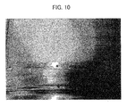
- FIG. 10 An aspect of a die surface of the obtained press die of the first embodiment is illustrated in FIG. 10 . It can be seen that a multitude of minute concave and convex portions is formed on a die surface 2 of the press die of the first embodiment, and that a luster of the die surface has been lost.
- a press die of comparative example 4 was obtained by carrying out only plating processing in the first embodiment. Concave and convex portions were not formed on a die surface of comparative example 4, and a roughness (Ry) of the die surface was 0 ⁇ m (see point f of FIG. 12 ). An aspect of a die surface of a press die of the obtained comparative example 4 is illustrated in FIG. 11 . Concave and convex portions were not formed on the die surface 2 of comparative example 4, and it can be seen that the die surface has luster.
- a press process of works was carried out repeatedly (5000 times) using press dies of the first embodiment, the second embodiment, and comparative example 1 to comparative example 4, and non-defective product rates of press-formed works thereof were measured.
- the non-defective product rate was obtained by measuring a height of deformities formed on press-formed works, assuming those with deformities of height less than 10 ⁇ m to be non-defective, and dividing the non-defective product quantity by the total number of times that the press process was carried out.
- a non-defective product rate for works for which the press process was carried out using a press die of the first embodiment and the second embodiment was at least 80%, and even when the press process was carried out repeatedly, it can be seen that a high non-defective product rate is maintained.
- a press die of a third embodiment was obtained in which a multitude of concave portions was formed on a die surface.
- a press die including a substantially planar surface portion in which a radius of curvature of a die surface was 10 mm was obtained in which a multitude of concave portions was formed on a die surface.
- a press die including a curved surface portion in which a radius of curvature of a die surface was 5 mm was obtained in which a multitude of concave portions was formed on a die surface.
- a press die including a curved surface portion in which a radius of curvature of a die surface was 3 mm Except for having used a press die including a curved surface portion in which a radius of curvature of a die surface was 3 mm, with a method similar to that of the third embodiment, a press die of comparative example 6 was obtained in which a multitude of concave portions was formed on a die surface.
Landscapes
- Chemical & Material Sciences (AREA)
- Engineering & Computer Science (AREA)
- Chemical Kinetics & Catalysis (AREA)
- Electrochemistry (AREA)
- Materials Engineering (AREA)
- Metallurgy (AREA)
- Organic Chemistry (AREA)
- Mechanical Engineering (AREA)
- Mounting, Exchange, And Manufacturing Of Dies (AREA)
- Shaping Metal By Deep-Drawing, Or The Like (AREA)
Abstract
Description
- The present invention relates to a press die for sheet metal forming, a processing method of a surface of the press die, and a manufacturing method of a vehicle body.
- Conventionally, forming of outer panel components of an automobile and the like have been carried out by press forming, in which a work is press processed using a press die. Generally, it is preferred that a press die used in a press process be such that the die surface, which is a contact surface with a work in the press die, be smoothed. By smoothing the die surface, it is possible to increase surface precision of a work (outer panel components) formed.
- As a method for smoothing a die surface, the applicant proposes a processing method of a die surface and a die for which the processing method has been applied (see Patent Document 1) in which, first, a forming surface of a die is formed by a cutting process, then a synthetic resin is applied to the formed die surface, and next shot blasting is performed for smoothing a shape of the die surface. According to a method described in
Patent Document 1, by a cutting process, it is possible effectively to grind high spots that are leftover from cutting generated on a die surface, thereby efficiently carrying out smoothing of a die surface. - Patent Document 1: Japanese Examined Patent Application Publication No.
Hei 8-263 - However, in the press die described in
Patent Document 1, in a case of repeatedly carrying out a press process in which foreign material of iron dust or other foreign particles or the like have adhered to the surface of the press die, large irregularities were formed on the surface of the work after a press process, having arisen from the foreign material (seeFIG. 13 ), and these eventually became a problem for quality of the product. In other words, there is a problem in that, as a press process is repeated, foreign material of iron dust or the like becomes caught in the surface of the press die, and the incidence rate of defective products becomes higher. - Therefore, the present invention has the objective of providing a press die for sheet metal forming, a processing method of a surface of the press die, and a manufacturing method of a vehicle body, capable of maintaining a high rate of non-defective works after a press process. Means for Solving the Problems
- The present inventors discovered that, by forming a multitude of concave portions of prescribed depth in a die surface, it was possible to achieve the above-mentioned objective, and this lead to completing the present invention. More specifically, the present invention provides the following. According to a first aspect, a press die for sheet metal forming has a multitude of concave portions in a die surface, in which a roughness (Ry) of the die surface is 30 to 38 µm. According to a second aspect, the press die for sheet metal forming as described in the first aspect has a plated layer on the die surface. According to a third aspect, in the press die for sheet metal forming as described in the second aspect, the plated layer has a thickness of 5 to 30 µm.
- According to a fourth aspect, in the press die for sheet metal forming as described in the second or third aspect, the plated layer is formed by electroplating.
- According to a fifth aspect, in the press die for sheet metal forming as described in the fourth aspect, the electroplating is chrome plating.
- According to a sixth aspect, in a press die for sheet metal forming, in a die having a plated layer, a roughness (Ry) of the die surface is 30 to 38 µm.
- According to a seventh aspect, in a processing method of a surface of a press die for sheet metal forming, a shot blast process is performed on the surface of the press die, forming a multitude of concave portions, and then a polishing process is performed on the surface of the press die to which a shot blast process was performed, to make a roughness (Ry) on the surface of the press die be 30 to 38 µm.
- According to an eighth aspect, in the processing method of a surface of a press die for sheet metal forming as described in the seventh aspect, prior to performing the shot blast process, plating processing is performed on the press die surface.
- According to a ninth aspect, a press die has had surfacing processing performed by way of the processing method of the surface of the press die for sheet metal forming as described in the seventh or eighth aspect.
- According to a tenth aspect, a maintenance method of the die surface in the press die for sheet metal forming as described in any one of the second to sixth aspects, the maintenance method includes: a step of removing the plated layer, a step of forming a new plated layer on the die surface from which the plated layer was removed, a step of forming a multitude of concave and convex portions by performing a shot blast process on the new plated layer, and a step of performing polishing processing on the new plated layer on which the multitude of concave and convex portions has been formed, to make a roughness (Ry) of the die surface be 30 to 38 µm.
- According to an eleventh aspect, a press die for sheet metal forming has a curved surface portion in which a die surface is formed of a curved surface and a substantially planar surface portion in which a die surface is formed of a substantially planar surface, in which a multitude of concave portions has been formed only on the die surface in the substantially planar surface portion.
- According to a twelfth aspect, in the press die for sheet metal forming as described in the eleventh aspect, the die surface in the curved surface portion has a radius of curvature of no greater than 5 mm, and the die surface in the substantially planar surface portion has a radius of curvature of greater than 5 mm.
- According to a thirteenth aspect, in the press die for sheet metal forming as described in the eleventh or twelfth aspect, a roughness (Ry) is 30 to 38 µm in the die surface of the substantially planar surface portion in which the multitude of concave portions has been formed.
- According to a fourteenth aspect, in the press die for sheet metal forming as described in any of the eleventh to thirteenth aspects, the die surface in the curved surface portion and the substantially planar surface portion has a plated layer.
- According to a fifteenth aspect, in the press die for sheet metal forming as described in the fourteenth aspect, the plated layer has a thickness of 5 to 30µm.
- According to a sixteenth aspect, in the press die for sheet metal forming as described in the fourteenth or fifteenth aspect, the plated layer is formed by electroplating.
- According to a seventeenth aspect, in the press die for sheet metal forming as described in the sixteenth aspect, the electroplating is chrome plating.
- According to an eighteenth aspect, a press die for sheet metal forming is characterized in that, in the press die for sheet metal forming including a three-dimensional die surface having a curved surface portion and a substantially planar surface portion, a shot blast process is performed on the substantially planar surface portion to exclude the curved surface portion, thereby forming a multitude of concave portions.
- According to a nineteenth aspect, a surface processing method of a press die for sheet metal forming has a curved surface portion in which the die surface is formed of a curved surface and a substantially planar surface portion in which the die surface is formed of a substantially planar surface, including a shot blast process step of forming a multitude of concave portions by performing a shot blast process on only the die surface in the substantially planar surface portion.
- According to a twentieth aspect, the surface processing method for a press die for sheet metal forming as described in the nineteenth aspect includes a polishing process step of performing a polishing process on the die surface on which the multitude of concave portions has been formed in the shot blast process step, after the shot blast process step.
- According to a twenty-first aspect, the surface processing method of a press die for sheet metal forming as described in the twentieth aspect is characterized in that in the polishing process step, a roughness (Ry) in the die surface of the substantially planar surface portion in which the multitude of concave portions has been formed has been adjusted to be 30 to 38 µm.
- According to a twenty-second aspect, the surface processing method of a press die for sheet metal forming as described in the twentieth or twenty-first aspect includes, before the shot blast process step, a masking step of performing masking processing on at least the die surface in the curved surface portion.
- According to a twenty-third aspect, the processing method of a surface of a press die for sheet metal forming as described in the twenty-second aspect includes, before the masking step, a plating step of performing plating processing on a surface of the press die.
- According to a twenty-fourth aspect, a press die for sheet metal forming has had surface processing performed thereto by a processing method of a press die surface for sheet metal forming as described in any one of the nineteenth to twenty-third aspects.
- According to a twenty-fifth aspect, a maintenance method of a die surface in a press die for metal, as described in any one of the fourteenth to seventeenth aspects, includes a plated layer removal step of removing the plated layer; a re-plating step of forming a new plated layer on the die surface in the curved surface portion and the substantially planar surface portion from which the plated layer was removed in the plated layer removal step; a masking step of performing masking processing at least on the die surface of the curved surface portion in the new plated layer formed in the re-plating step; a shot blast process step of, after the masking step, performing a shot blast process on at least one portion on the die surface of the substantially planar surface portion, thereby forming a multitude of concave and convex portions; and a polishing process step of performing a polishing process on the new plated layer on the die surface on which the multitude of concave and convex portions has been formed.
- According to a twenty-sixth aspect, a manufacturing method of a vehicle body includes a forming step of forming outer panel components of a vehicle body using a press die for sheet metal forming as described in any one of the first to sixth aspects and the eleventh to eighteenth aspects, and a welding step of welding at least one outer panel component formed in the forming step, thereby constructing an entirety of a vehicle body.
- According to a twenty-seventh aspect, a manufacturing method of industrial products includes a step of manufacturing a work by forming a sheet member using a press die for sheet metal forming as described in any of the first to sixth and eleventh to eighteenth aspects, and a welding step of manufacturing major components of industrial goods by welding a plurality of the work.
- According to a processing method of a press die for sheet metal forming and a press die surface of the present invention, since a die surface has a multitude of concave portions of prescribed depth, even in a case in which such foreign matter as iron dust and the like adhere to the die surface, large concave and convex portions are not formed on the work after a press process, and it is possible to maintain a high rate of non-defective works after the press process.
-
-
FIG. 1 is a view illustrating a state of carrying out a press process using a press die of the present invention; -
FIG. 2A is a view illustrating a state in which plating process has been performed in a processing method of a press die surface of a first embodiment; -
FIG. 2B is a view illustrating a state in which a shot blast process has been performed in a processing method of a press die surface of the first embodiment; -
FIG. 2C is a view illustrating a state in which a polishing process has been performed in a processing method of a press die surface of the first embodiment; -
FIG. 3A is a perspective view illustrating a press die for sheet metal forming of the first embodiment, and illustrates a press die for automobile hood manufacturing; -
FIG. 3B is a perspective view illustrating a press die for sheet metal forming of the first embodiment, and illustrates a press die for automobile roof panel manufacturing; -
FIG. 4 is a cross-sectional view along a line "X-X" ofFIG. 1A ; -
FIG. 5 is a view illustrating a state of carrying out a press process using a press die of the present invention; -
FIG. 6A is a view illustrating a plating step in a processing method of a press die surface of a second embodiment; -
FIG. 6B is a view illustrating a masking step in a processing method of a press die surface of the second embodiment; -
FIG. 6C is a view illustrating a shot blast process step in a processing method of a press die surface of the second embodiment; -
FIG. 6D is a view illustrating a polishing process step in a processing method of a press die surface of the second embodiment; -
FIG. 7 is a flow diagram illustrating an embodiment of a manufacturing method of a vehicle body of the present invention; -
FIG. 8 is a diagram illustrating an outline of a preset step and a vehicle construction step in a manufacturing method of a vehicle body of the present invention; -
FIG. 9A is a diagram illustrating an example of a vehicle body construction step in a manufacturing method of a vehicle body of the present invention; -
FIG. 9B is a diagram illustrating another example of a vehicle body construction step in a manufacturing method of a vehicle body of the present invention; -
FIG. 10 is a diagram illustrating an aspect of a die surface of a press die of the first embodiment; -
FIG. 11 is a diagram illustrating an aspect of a die surface of a press die of comparative example 4; -
FIG. 12 is a diagram illustrating a rate of non-defective works formed using press dies of each embodiment and comparative example; and -
FIG. 13 is a view illustrating a state of carrying out a press process using a conventional press die. -
- 1
- Press Die
- 2
- Die Surface
- 3
- Concave Portion
- 4
- Foreign Matter
- 5
- Work
- 6
- Plated Layer
- 7
- Deformity
- 8
- Injector
- 9
- Masking Member
- 11
- Curved Surface Portion
- 12
- Substantially Planar Surface Portion
- Below, the present invention is explained based on a first embodiment, which is one preferred embodiment, with reference to
FIG. 1 . -
FIG. 1 is a view illustrating a state of carrying out a press process using a press die for sheet metal forming of the present invention. - A press die for sheet metal forming (hereafter referred to as just "press die" as well) 1 of the first embodiment, as illustrated in
FIG. 1 , has a multitude ofconcave portions 3 in adie surface 2. Furthermore, a roughness (Ry) of adie surface 2 on which this multitude ofconcave portions 3 has been formed is within a range of 30 to 38 µm. - Moreover, "roughness" in the present specification refers to "surface roughness" as stipulated in JIS B0601-1994, and "(Ry)" indicates a height from a lowest valley to a highest peak for each reference length: a maximum height.
- In the present invention, by a
die surface 2 having a multitude ofconcave portions 3, even in a case in which a fineforeign matter 4 of iron dust and the like becomes caught in adie surface 2, because theforeign matter 4 enters into theconcave portions 3, large concave and convex portions do not form in the work surface after a press process. Moreover, as theforeign matter 4 adhering to thedie surface 2, aside from the abovementioned iron dust, waste fibers or flakes of coating and the like can be given. - Furthermore, by setting the roughness (Ry) of the
die surface 2 in which the multitude ofconcave portions 3 is formed to within a range of 30 to 38 µm, it is possible to prevent a reduction in surface precision of awork 5 after a press process due to existence of the multitude ofconcave portions 3, while being able to prevent formation of large concave and convex portions on a surface of thework 5 after a press process, even in a case of adherence of relatively large-sizedforeign matter 4. - More specifically, in a case in which the
foreign matter 4 is iron dust, even at a time of adherence of iron dust of particle size of a maximum of approximately 15 µm on a die surface, a height of concave and convex portions (hereafter referred to as "deformity 7" as well) formed on a surface of awork 5 after a press process can be limited to approximately 9 µm. Furthermore, in a case in which theforeign matter 4 is ordinary dirt other than iron dust, even in a case offoreign matter 4 of particle size of a maximum of approximately 25 µm adhering on a die surface, a height of adeformity 7 formed on a surface of awork 5 after a press process can be limited to approximately 9 µm. - Ordinarily, in a case in which a
deformity 7 formed on a surface of awork 5 after a press process is less than 10 µm, it is difficult to confirm the existence of thedeformity 7 visually, and a formedwork 5 is assumed to be non-defective. On the other hand, in a case in which adeformity 7 is at least 10 µm, the existence of thedeformity 7 is confirmed visually, a formedwork 5 is assumed defective, and repair work in which thedeformity 7 is ground becomes necessary. - Therefore, as described above, according to the press die 1 of the present embodiment, in which a multitude of
concave portions 3 is formed on adie surface 2, and a roughness (Ry) of thedie surface 2 formed by this multitude ofconcave portions 3 is set to be 30 to 38 µm, it is possible to maintain a high rate of non-defective products, even whenforeign matter 4 adheres onto thedie surface 2. - Furthermore, because in many cases, repair work of defective products is carried out by hand, necessitating much labor and cost, by the formed works 5 maintaining a high rate of non-defective products, it is possible to attempt to improve manufacturing efficiency in a press process step while reducing cost.
- Moreover, in a case in which a roughness (Ry) of the
die surface 2 is less than 30 µm, in a case whereforeign matter 4 cuts in, alarge deformity 7 is formed after a press process, and the rate of non-defective products ofworks 5 is lowered. In a case in which a roughness (Ry) of thedie surface 2 is greater than 38 µm, due to the presence of the multitude ofconcave portions 3 thus formed, surface precision of theworks 5 after the press process is lowered. - As a method for forming a multitude of
concave portions 3 on thedie surface 2, for example, a method may be given in which, after performing a shot blast process to thedie surface 2 and forming a multitude of concave and convex portions, a polishing process is performed to thedie surface 2, and a roughness (Ry) of thedie surface 2 in which the multitude ofconcave portions 3 has been formed is adjusted to be 30 to 38 µm (details to be described later). - Furthermore, using a roller (not illustrated) including a multitude of concave and convex portions of a prescribed depth in forming a multitude of
concave portions 3 on thedie surface 2 is also acceptable. - As illustrated in
FIG. 1 , apress die 1 having a plated layer is preferred. In other words, it is preferable that a platedlayer 6 be formed on thedie surface 2. By the platedlayer 6 being formed on thedie surface 2, strength of thedie surface 2 is increased, increasing abrasion resistance of apress die 1. Furthermore, it is also possible to increase corrosion resistance of the press die 1, thereby lengthening a usable life of the press die 1. - The plated
layer 6 may be formed by electroplating such as industrial chrome plating, nickel-tungsten plating, dispersion nickel plating, or rhodium plating, or by such electroless plating as electroless nickel plating, and in particular, it is preferable, from a durability perspective, to form thereof by industrial chrome plating. A thickness of the platedlayer 6, from a perspective of durability and reliability as an industrial plating, would preferably be 5 to 30 µm, and more preferably 15 to 25 µm. - Moreover, even when the present invention is applied to a die for which plating processing has not been applied, the effect is the same.
- Next, a processing method of a press die surface of a first embodiment is explained with reference to
FIGS. 2A to 2C. FIGS. 2A to 2C are views illustrating each step in a processing method of a press die surface of a first embodiment. - A processing method of a press die surface of a first embodiment includes 1) a plating processing step, 2) a shot blast process step, and 3) a polishing process step.
- First, plating processing is performed on a
die surface 2, which is a contact surface with a work in a press die 1 (seeFIG. 2A ). The plating processing, for example, can be carried out by a processing method of industrial chrome plating, which is a common electroplating, and a platedlayer 6 is formed on thedie surface 2 by the plating method. - For the press die 1, for example, it is possible to use such cast-iron dies as FC250, FC300, FCD500, and the like.
- Next, a shot blast process is performed on the
die surface 2 on which plating processing has been applied (seeFIG. 2B ). By a shot blast process, a multitude of concave and convex portions is formed on the die surface. The shot blast process, as illustrated inFIG. 2B , is carried out by spraying shot blasting media of a prescribed particle diameter from aninjection device 8 onto adie surface 2 after the plating process. As shot blasting media used in the shot blast process, for example, it is possible to use glass beads, aluminum beads, ceramic beads, and the like. Furthermore, a particle diameter of shot blasting media, from a perspective of forming aconcave portion 3 of preferable depth, is preferably 0.1 to 0.3 mm. In addition, a shot blasting pressure in the shot blast process, also from a perspective of forming aconcave portion 3 of preferable depth, is preferably 0.5 to 1.2 MPa. - Moreover, here, a roughness (Ry) of a
die surface 2 in which a multitude ofconcave portions 3 is formed after the shot blast process, from a perspective of assuming a roughness (Ry) of thedie surface 2 after a polishing step (after final finishing) to be described later to be 30 to 38 µm, is 35 to 43 µm. In other words, in a polishing step after a shot blast process, approximately 5 µm is planed from the overall die. - Next, a polishing process is performed to the
die surface 2 on which a multitude ofconcave portions 3 has been formed by a shot blast process (seeFIG. 2C ). By performing this polishing process, a shape of a peak part of a convex portion formed between twoconcave portions die surface 2 on which a multitude ofconcave portions 3 is formed is adjusted to be within a range of 30 to 38 µm. In this way, by flattening peak parts of convex portions, a surface precision of awork 5 after a press process is further increased. The polishing process can be carried out using a file or the like; for example, 600 to 800 grain sandpaper can be used. Moreover, in the polishing process step, it is acceptable to adopt a polishing method other than sandpaper. - By way of this polishing process, it is preferable to finish the
die surface 2 so that the roughness (Ry), which is a concave/convex average, is 35 µm. - According to a processing method of a press die surface of the first embodiment, since a multitude of
concave portions 3 having prescribed depth is formed on thedie surface 2, even in a case in which suchforeign matter 4 as iron dust or the like become adhered onto thedie surface 2, it is possible to obtain apress die 1 which can maintain a high non-defective product rate ofworks 5 after the press process. - Furthermore, by performing a shot blast process after performing plating processing to the
die surface 2, plating hardness is increased and, consequently, abrasion-resistance of the press die 1 is increased. - Furthermore, according to a processing method of a press die surface of the first embodiment, since a die can have a plated layer by having a plating processing step, a multitude of concave portions is formed on a plated layer part of a die surface. Therefore, in a case in which a die is used repeatedly in a press process and a roughness (Ry) of a die surface becomes outside a range of 30 to 38 µm, it is possible to recover a roughness (Ry) of a die surface easily by removing a plated layer, and performing re-plating processing, a shot blast process, and a polishing process.
- In other words, according to a press die which has had surface processing applied by a processing method of a press die surface of the first embodiment, it is possible easily to carry out maintenance for preserving a roughness (Ry) of a die surface to within a prescribed range.
- Moreover, a deterioration measurement of a roughness (Ry) of a die surface can easily be measured using a surface roughness measuring instrument to be described later. Furthermore, removal of a plated layer can be carried out, for example, by soaking a die having a plated layer in a solution such as acid or the like.
- It is desirable appropriately to carry out maintenance of a die surface while using a measured value of roughness (Ry) by a suitable surface roughness measuring instrument as a reference. However, it is possible to carry out maintenance with a number of presses (number of shot blastings), an operating time of a die, and a frequency of debris getting caught as control items.
- Processing of a press die in a first embodiment can be performed to an entire surface of the
die surface 2, but it is preferable to be performed especially on flat surfaces for which the presence ofdeformities 7 after a press process is easily visually recognized, that is, only to regions of a low degree of curvature at a time of a press process. Regions of a low degree of curvature can havedeformities 7 after a press process easily recognized, but on the other hand, force applied to a thedie surface 2 at a time of a press process is relatively small compared to regions of a high degree of curvature. As a result, by forming a multitude ofconcave portions 3 only on regions of a low degree of curvature, wear on shapes ofconcave portions 3 becomes less, and it is possible to lengthen a usable life of a press die. - It is possible preferably to use a press die for which the processing method of the press die surface of the above-mentioned first embodiment has been performed on a shape for an outer panel component of a vehicle body of an automobile or the like. Furthermore, identical results were obtained whether the outer panel component was iron or aluminum.
- Next, a second embodiment of the present invention is explained with reference to
FIGS. 3A to 5 . -
FIGS. 3A and 3B are perspective views indicating apress die 1 of a second embodiment of the present invention, in whichFIG. 3A illustrates a press die for a hood of an automobile, andFIG. 3B illustrates a press die for a roof panel of an automobile.FIG. 4 is a cross-sectional view taken along a line "X-X" ofFIG. 3A .FIG. 5 is a view illustrating a state of carrying out a press process using a press die for sheet metal forming of the present invention. - Moreover, in explaining the following second embodiment, identical symbols are associated with identical constituent elements of the first embodiment, for which explanations will be omitted or simplified.
- A press die 1 of the second embodiment, as illustrated in
FIGS. 3A to 5 , is a press die for sheet metal forming (hereafter referred to as a "press die" as well) 1 having acurved surface portion 11 and a substantiallyplanar surface portion 12, and is apress die 1 placed and used so that adie surface 2 faces upwards. In a case of carrying out a press process using the press die 1 of the second embodiment, a sheet member of steel sheet or the like is placed on an upper side of the press die 1, a second press die (not illustrated) having a die surface of a shape corresponding to a shape of thedie surface 2 on the press die 1 on an upper side of a sheet member is placed, and the sheet member is press-formed by moving the press die 1 and/or the press die 2 in a vertical direction. - Moreover, on a
press die 1 of the present invention, thecurved surface portion 11 indicates a part formed by a curved surface in which a radius of curvature of thedie surface 2 is no more than 5 mm, and the substantiallyplanar surface portion 12 indicates a part formed by a substantially planar surface in which a radius of curvature of thedie surface 2 is larger than 5 mm. - The press die 1 of the second embodiment is formed with a multitude of
concave portions 3 only on the die surface of the substantiallyplanar surface portion 12. Furthermore, in the second embodiment, in a state in which adie 1 is positioned for a purpose of carrying out a press process, the substantiallyplanar surface portion 12, as illustrated inFIG. 4 , has ahorizontal area 12b and asloped area 12a. In addition, a multitude ofconcave portions 3 is formed on adie surface 2 of thehorizontal area 12b in the substantiallyplanar surface portion 12. - On the other hand, a multitude of
concave portions 3 is not formed on adie surface 2 of thecurved surface portion 11. Furthermore, a multitude ofconcave portions 3 is not formed in a vicinity of a border with thecurved surface portion 11 in the substantiallyplanar surface portion 12, and is not formed in a slopedarea 12a in the substantiallyplanar surface portion 12. - Moreover, a
horizontal area 12b indicates an area to be placed in which, in the substantiallyplanar surface portion 12, an inclination angle with respect to a horizontal surface of the substantiallyplanar surface portion 12 is preferably less than 45 degrees, more preferably less than 30 degrees, and most preferably less than 20 degrees. A slopedarea 12a indicates an area to be positioned so that an inclination angle with respect to a horizontal surface of the substantiallyplanar surface portion 12 is preferably at least 45 degrees, more preferably at least 30 degrees, and most preferably at least 20 degrees. - Due to the press die 1 of the present invention having a multitude of
concave portions 3 in adie surface 2 of a substantiallyplanar surface portion 12, even in a case in which fineforeign matter 4 of iron dust and the like becomes caught in thedie surface 2, because theforeign matter 4 entersconcave portions 3, large concave and convex portions are not formed on awork 5 surface after a press process. - Moreover, as the
foreign matter 4 adhering to thedie surface 2, waste fibers or flakes of coating and the like can be given. - Furthermore, a multitude of
concave portions 3 is not formed on thecurved surface portion 11, but is only formed on the substantiallyplanar surface portion 12.Foreign matter 4 of iron dust and the like do not adhere easily to thecurved surface portion 11 with a small radius of curvature (of a large curvature) on the press die 1, but adhere easily to the substantiallyplanar surface portion 12 with a large radius of curvature (of a small curvature). In other words,foreign matter 4 of iron dust and the like generated at a time of press forming adheres relatively more on the substantiallyplanar surface portion 12 than on thecurved surface portion 11 on the press die 1. Therefore, by forming a multitude ofconcave portions 3 on only the substantiallyplanar surface portion 12, it is possible effectively to prevent adverse effects to awork 5 surface byforeign matter 4 adhering to thedie surface 2. - On the other hand, a multitude of
concave portions 3 is not formed on thecurved surface portion 11 on the press die 1. On thecurved surface portion 11 on the press die 1, there are present parts of great curvature at the time of forming, that is, parts in which theword 5 has been significantly deformed at the time of press processing. As a result, in a case in which a multitude ofconcave portions 3 is formed on acurved surface portion 11 of great curvature, there is a risk that scratches (abrasions) may form on a work surface due to the presence of the multitude ofconcave portions 3. In this regard, in the press die 1 of the second embodiment, since a multitude ofconcave portions 3 is not formed on thedie surface 2 on thecurved surface portion 11, abrasions due to a multitude ofconcave portions 3 do not arise on a work surface formed by a press process. - Furthermore, a multitude of
concave portions 3 is not formed on a slopedarea 12a on a substantiallyplanar surface portion 12, either. On the slopedarea 12a, since thedie surface 2 is placed so as to be sloped,foreign matter 4 of iron dust and the like slide off thedie surface 2 easily, so it is difficult for theforeign matter 4 to adhere to thedie surface 2 on the slopedarea 12a. Therefore, even in a case in which a multitude ofconcave portions 3 is not formed on adie surface 2 on a slopedarea 12a, it is difficult for concave and convex portions to arise on a surface of awork 5 after a press process due toforeign matter 4 of iron dust and the like. - In a case in which a multitude of
concave portions 3 is not to be formed on a slopedarea 12a on a substantiallyplanar surface portion 12, a step of forming a multitude ofconcave portions 3 on the slopedarea 12a becomes unnecessary, so it becomes possible to limit manufacturing costs of the press die 1. - Furthermore, in the press die 1 of the second embodiment, a roughness (Ry) of a
die surface 2 on a substantiallyplanar surface portion 12 on which a multitude ofconcave portions 3 has been formed is set to be in the range of 30 to 38 µm. - In the second embodiment, by setting a roughness (Ry) of a substantially
planar surface portion 12 on which a multitude ofconcave portions 3 has been formed to be in the range of 30 to 38 µm, it is possible to prevent a lowering of surface precision of awork 5 on the substantiallyplanar surface portion 12 after a press process due to a presence of a multitude ofconcave portions 3, while it is possible to prevent formation of large concave and convex portions on a surface of awork 5 after a press process, even in a case in whichforeign matter 4 of relatively large size adhere to thedie surface 2. - The press die 1, as illustrated in
FIG. 5 , preferably has a platedlayer 6. Moreover, the effect is identical even when the present invention is applied to a die for which plating processing has not been performed. - Next, a press die surface of the second embodiment is explained with reference to
FIGS. 6A to 6D. FIGS. 6A to 6D are views illustrating each step in a processing method of a press die surface of the second embodiment. - The processing method of a press die surface of the second embodiment includes: 1) a plating processing step, 2) a masking step, 3) a shot blast process step, and 4) a polishing process step.
- First, plating processing is performed to a
die surface 2, which is a contact surface with a work on a press die 1 (seeFIG. 6A ). The plating processing is carried out with a method similar to that of the first embodiment. - Next, masking processing is performed to a
curved surface portion 11 and a boundary area of acurved surface portion 11 and a substantiallyplanar surface portion 12, on adie surface 2 to which plating processing has been performed (seeFIG. 6B ). Masking processing, for example, can be carried out by adhering a maskingmaterial 9 to acurved surface portion 11 and a boundary area of acurved surface portion 11 and a substantiallyplanar surface portion 12, on thedie surface 2. As a maskingmaterial 9, aluminum tape, vinyl tape, or the like can be given. - By performing the masking process, in a shot blast step to be described later, it is possible to prevent a multitude of
concave portions 3 from being formed on thecurved surface portion 11. In a case of performing masking processing to thecurved surface portion 11 and the border area of thecurved surface portion 11 and the substantiallyplanar surface portion 12, it is preferable that the masking processing be performed to an area approximately 10 mm from the boundary of thecurved portion 11 and the substantiallyplanar surface portion 12 on the substantiallyplanar surface portion 12. - Moreover, the masking processing, in the present embodiment, is performed to the
curved surface portion 11 and the boundary area of thecurved surface portion 11 and the substantiallyplanar surface portion 12, but performing at least to thecurved surface portion 11 is acceptable. - Next, on a substantially
planar surface portion 12 on adie surface 2 to which plating processing has been performed, a shot blast process is performed with a similar method to that of the first embodiment (seeFIG. 6C ). By a shot blast process, a multitude of concave and convex portions is formed on a substantiallyplanar surface portion 12 on adie surface 2. - Moreover, since masking processing is performed to a
curved surface portion 11 of the press die 1 to which a shot blast process has been performed, and to a boundary area of thecurved surface portion 11 and the substantiallyplanar surface portion 12, even if shot blasting media is sprayed on thecurved surface portion 11 and on the boundary area of thecurved surface portion 11 and the substantiallyplanar surface portion 12, a multitude of concave and convex portions is not formed on the area. Here, in a case in which masking processing is not performed to thecurved surface portion 11, a multitude ofconcave portions 3 is formed on thecurved surface portion 11 as well, while, by a shot blast process, there is a risk in that a shape of thecurved surface portion 11 with a small radius of curvature may change. - Furthermore, in the second embodiment, a shot blast process is not performed to a sloped
area 12a on the substantiallyplanar surface portion 12, and a multitude ofconcave portions 3 is not formed on thedie surface 2 on the slopedarea 12a (seeFIG. 4 ). In a case in which a shot blast process is performed to the slopedarea 12a on the substantiallyplanar surface portion 12, shot blasting media is not uniformly sprayed on the slopeddie surface 2, and there is a risk in that a depth of a multitude ofconcave portions 3 formed on thedie surface 2 may be nonuniform. - A roughness (Ry) of the
die surface 2 on the substantiallyplanar surface portion 12 on which a multitude ofconcave portions 3 has been formed after a shot blast process, from a perspective of setting a roughness (Ry) on adie surface 2 after a polishing process step (after final finishing) to be 30 to 38 µm, should preferably be 30 to 43 µm. In other words, in a polishing step after a shot blast process, approximately 5 µm of the surface is planed from the overall die. - Next, to the
die surface 2 of the substantiallyplanar surface portion 12 on which a multitude ofconcave portions 3 has been formed by a shot blast process, a polishing process is performed with a similar method to that of the first embodiment (seeFIG. 6D ). - According to the processing method of the press die surface of the second embodiment, since a multitude of
concave portions 3 having a prescribed depth is formed on thedie surface 2 of the substantiallyplanar surface portion 12 on the press die 1 having acurved surface portion 11 and a substantiallyplanar surface portion 12, even in a case in which suchforeign matter 4 as iron dust and the like adhere to thedie surface 2, it is possible to obtain apress die 1 which can maintain a high non-defective product rate ofworks 5 after a press process. - Furthermore, after performing plating processing on the
die surface 2, by performing a shot blast process, plating hardness is increased and, consequently, wear-resistance of the press die 1 is increased. - In addition, according to the processing method of the press die surface of the second embodiment, since a shot blast process is performed after masking processing is performed at least to the
curved surface portion 11, a multitude ofconcave portions 3 is not formed on thecurved surface portion 11, and it is possible to form a multitude ofconcave portions 3 on only the substantiallyplanar surface portion 12. - Moreover, when a shot blast process is performed in order to form a multitude of
concave portions 3 on thecurved surface portion 11, which is a region of a small radius of curvature of the press die 1, this can have the opposite effect of marring the outer shape of the press die 1, but by way of the press die 1 of the second embodiment, it is possible to prevent damage to the form of this press die 1. - Furthermore, according to the processing method of the press die surface of the second embodiment, since the press die has a plated layer by having a plating processing step, a multitude of concave portions is formed on the plated layer part on the die surface. Therefore, in a case in which a die is used repeatedly in a press process and a roughness (Ry) of a die surface becomes outside a range of 30 to 38 µm, it is possible easily to form again a multitude of concave portions only on a substantially planar surface portion on the press die by removing a plated layer, and performing re-plating processing, masking processing, a shot blast process, and a polishing process to recover a roughness (Ry) of the die surface.
- In other words, according to a press die for which surface processing has been applied by the processing method of the press die surface of the second embodiment, it is possible easily to carry out maintenance for preserving a roughness (Ry) of a die surface to within a prescribed range.
- In this maintenance, aside from management of a value of roughness (Ry), it is preferable to carry out maintenance with the number of times of press and shot blasting, operating time of a die, and frequency of dirt getting caught as control
- Furthermore, the shot blast process to the press die surface in the second embodiment is performed only to the flat substantially planar surface portion in which presence of
deformities 7 after a press process is easily visually recognizable, that is to regions of shallow curvature at a time of a press process. Regions of shallow curvature are such that the presence ofdeformities 7 after a press process is easily visually recognized, while on the other hand, the force applied to thedie surface 2 at a time of a press process is relatively small compared to regions of great curvature. As a result, by a multitude ofconcave portions 3 being formed only on the substantiallyplanar surface portion 3 of shallow curvature, wear on the form of the multitude ofconcave portions 3 is lessened, and it is possible to lengthen a period of use of a press die. - The above-described press die to which the processing method of the second embodiment has been applied may preferably be used for forming components having curved surface portions and substantially planar surface portions, and in particular, for forming various outer panel components configuring a vehicle body and the like. Furthermore, an identical effect was obtained whether the outer panel component was iron or aluminum.
- Next, a preferable embodiment of a manufacturing method of a vehicle body using a press die of the present invention is explained with reference to
FIGS. 7 ,8 ,9A and 9B .FIG. 7 is a flow diagram illustrating an embodiment of a manufacturing method of a vehicle body of the present invention.FIG. 8 is a diagram illustrating an outline of a presetting step and a vehicle construction step in a manufacturing method of a vehicle body of the present invention.FIG. 9A is a diagram illustrating an example of a vehicle body construction step in a manufacturing method of a vehicle body of the present invention.FIG. 9B is a diagram illustrating another example of a vehicle body construction step in a manufacturing method of a vehicle body of the present invention. - The present embodiment is a manufacturing method of a vehicle body of the present invention applied to a manufacturing method of a vehicle body of an automobile.
- The present embodiment includes a forming step S2 of forming an outer panel component of a vehicle body using a press die of the present invention, and a welding step S3 of welding a plurality of outer panel components formed in the forming step.
- More particularly, a manufacturing method of a vehicle body of an automobile of the present embodiment, as illustrated in
FIGS. 7 and8 , has a shearing step S1 of shearing a coil of sheet steel; a forming step S2 of forming a shape of various outer panel components configuring a vehicle body by a press die in which a steel sheet has been sheared in the shearing step S1; a welding step (hereinafter, also referred to as a "component welding step") S3 of manufacturing each component of a vehicle body by welding a plurality of types of various outer panel components formed in the forming step S2; a presetting step S4 of positioning each component formed in the component welding step S3 at a prescribed location; and a vehicle body construction step S5 of forming a vehicle body by constructing each component positioned at a prescribed location in the presetting step S4. - Below, each step thereof is explained.
- In the shearing step S1, a coil of sheet steel delivered to a vehicle body plant is cut off into a prescribed form by shearing.
- In the forming step S2, the pulled flat steel sheet in the shearing step S1 is formed into a shape of various outer panel components configuring a vehicle body by a press apparatus (for example, a tandem press apparatus or the like) in the public domain using the press die. In the present embodiment, the press die 1, which has had the processing method of the press die surface of the present invention described above in this forming step performed thereto, is used, manufacturing various outer panel components configuring a vehicle body.
- Moreover, the press die to which the processing method of the press die surface of the present invention has been performed is especially preferably used in press forming of a roof panel, a side panel, a hood, such large pressed components as floor panels and the like, and various press components configuring these large pressed components. Furthermore, preferably usage is made in press forming of small pressed components of reinforced members and the like. Regarding forming of these small components, press forming using a generic press die other than the present invention is also acceptable.
- In the component welding step S3, a plurality of types of various outer panel components formed in the forming step S2 are welded, and each component configuring the vehicle body is manufactured. Welding in the component welding step S3 is carried out by a plurality of welding robots.
- As components formed in the component welding step S3, underbodies, side bodies, doors, roofs, hoods, trunk lids, and the like can be given.
- In the present embodiment, press components configuring each of these components are all formed using a die for sheet metal forming of the present invention.
- In the presetting step S4, as illustrated in
FIG. 8 , each component manufactured in the component welding step S3 is positioned placed at a prescribed position. - In the presetting step S4, first, an
underbody 21 is placed on acarriage 20b configuring atransfer mechanism 20. Thetransfer mechanism 20 includes arail 20a and acarriage 20b placed movably on therail 20a. - Next, in relation to the
underbody 21 placed on thecarriage 20b, each of the components of theroof 22, theside body 23, and the like are positioned placed at a prescribed position by arobot arm 24. Each component is moved in a state positioned at a prescribed location on thecarriage 20b, and sent to a vehicle body construction step S5. - In a vehicle body construction step S5, each component in a state of being positioned in a prescribed location in the presetting step S4 is welded, and a vehicle body (white body) 26 is constructed. Welding of each component in the vehicle construction step S5, as illustrated in
FIG. 6 , is carried out by awelding robot 25. - In this manner, a vehicle body (white body) 26 before performing a coating process thereto is manufactured.
- The vehicle body (white body) 26, manufactured after the vehicle body construction step is delivered to a coating plant, and various coating processing is performed to the vehicle body (white body) in a coating step (not illustrated).
- Moreover, the vehicle body construction step S5 constructing the
white body 26, as illustrated inFIGS. 8 and9A , is not limited to a vehicle construction step S5 of a monocoque method of constructing each component of theunderbody 21,roof 22,side body 23, and the like, configuring thewhite body 26, at one time. The vehicle construction step S5, as illustrated, for example, inFIG. 9B , may be a vehicle body construction step S5 of an inner framework method, composed of a step S5a of constructing aninner framework 28 configured by components of anunderbody 21, an inner-side side body 23a, across member 27, and the like; a step S5b of mounting thereafter anexterior side body 23b and the like on theinner framework 28; and a step S5c of mounting thereafter aroof 22 and the like additionally on theinner framework 28 on which theexterior side body 23b and the like have been mounted. The vehicle body construction step S5 of this inner framework method is used in manufacturing mainly high-grade vehicle types. - The press die of the die for sheet metal forming of the present invention is also preferably used in manufacturing various outer panel components configuring components used in the vehicle body construction step S5 of the abovementioned monocoque method, and any outer panel components of any various outer panel components configuring components used in each step (S5a, S5b, and S5c) in the vehicle body construction step S5 of the above-mentioned inner framework method.
- According to the manufacturing method of a vehicle body of the present embodiment, by using the press die 1 of the die for sheet metal forming of the present invention to which the processing method of the present invention has been applied in a forming step, various outer panel components after a press process become of a high non-defective product rate and, consequently, it becomes possible to increase a quality of vehicles manufactured after a welding process.
- Furthermore, since a non-defective product rate of outer panel components after a press process is high, that is, a quantity of defective products requiring repair work is low, it becomes possible to reduce repair man-hours, while increasing a manufacturing efficiency of vehicle bodies.
- Moreover, a vehicle body to which the manufacturing method of a vehicle body of the present invention is applied is not limited to the above-mentioned automobile, but it is possible to name bicycles, ATVs, outboard motors, and the like. In particular, metallic components configuring these vehicle bodies overall can be applied thereto.
- Furthermore, the press die of the present invention is used in forming of outer panel components of vehicle bodies, and is preferably used in forming of works configuring various industrial products in cogeneration systems, outer panel components and covers of airplanes, and the like. As materials of these works, iron, aluminum, or the like can be given.
- Next, the present invention is described in more detail based on the embodiment of the present invention, but the present invention is not limited to this.
- By the processing method of the above-described press die surface, surface processing is performed to a press die, and the press die of the first embodiment is manufactured.
- As plating processing, plating processing by a processing method of industrial chrome plating, which is common electroplating, is adopted, and plating processing is performed to a die surface by a plating processing method in the public domain. A thickness of a plated layer formed on a die surface is 20 µm.
- A radius of curvature on a die surface was measured, and a curved surface portion which was of a radius of curvature of no more than 5 mm, and a substantially planar surface portion which was of a radius of curvature of greater than 5 mm, were each identified. A masking process was performed using an aluminum tape on a curved surface portion. Measurement of a radius of curvature for a die surface was measured using an R-gauge.
- A shot blast process was performed to a die surface to which the masking process was performed to a curved surface portion thereof.
- In the shot blast process, glass beads of particle diameter 0.3 mm were used as shot blasting media, and were directly sprayed on a die surface with a shot pressure of 1.2 MPa. A roughness (Ry) of a die surface after the shot blast process was 44 µm.
- A polishing process was performed on a die surface to which a multitude of concave portions was formed by the shot blast process. The polishing process was carried out using 600 to 800 grain sandpaper, and an average depth of the multitude of concave portions formed on the die surface was adjusted to be 35 µm (see point a of
FIG. 12 ). - A roughness (Ry) of a die surface after the above-mentioned shot blast process and a roughness (Ry) of the die surface after the polishing process were measured using the <Measurement Method of Roughness of a Die Surface> indicated in the following.
- The roughness measurement, using surface roughness measuring instrumenty E-30A or E-35B manufactured by Tokyo Seimitsu Co., Ltd. (ACCRETECH) determined a roughness (Ry) of a die surface after the shot blast process and a roughness (Ry) of a die surface after polishing process.
- In this manner, the press die of the first embodiment was obtained. An aspect of a die surface of the obtained press die of the first embodiment is illustrated in
FIG. 10 . It can be seen that a multitude of minute concave and convex portions is formed on adie surface 2 of the press die of the first embodiment, and that a luster of the die surface has been lost. - In the shot blast process in the first embodiment, using glass beads of particle diameter 0.3 mm, aside from adjusting a roughness (Ry) of a die surface after a polishing process to be 30 µm, a press die of the second embodiment was obtained with a similar method to that of the first embodiment (see point b of
FIG. 12 ). - In the shot blast process in the first embodiment, using glass beads of particle diameter 0.3 mm, aside from adjusting a roughness (Ry) of a die surface after a polishing process to be 25 µm, a press die of comparative example 1 was obtained with a similar method to that of the first embodiment (see point c of
FIG. 12 ). - In the shot blast process in the first embodiment, using glass beads of particle diameter 0.3 mm, aside from adjusting a roughness (Ry) of a die surface after a polishing process to be 43 µm, a press die of comparative example 2 was obtained with a similar method to that of the first embodiment (see point d of
FIG. 12 ). - In the shot blast process in the first embodiment, using glass beads of particle diameter 0.3 mm, aside from adjusting a roughness (Ry) of a die surface after a polishing process to be 45 µm, a press die of comparative example 3 was obtained with a similar method to that of the first embodiment (see point e of
FIG. 12 ). - A press die of comparative example 4 was obtained by carrying out only plating processing in the first embodiment. Concave and convex portions were not formed on a die surface of comparative example 4, and a roughness (Ry) of the die surface was 0 µm (see point f of
FIG. 12 ). An aspect of a die surface of a press die of the obtained comparative example 4 is illustrated inFIG. 11 . Concave and convex portions were not formed on thedie surface 2 of comparative example 4, and it can be seen that the die surface has luster. - A press process of works was carried out repeatedly (5000 times) using press dies of the first embodiment, the second embodiment, and comparative example 1 to comparative example 4, and non-defective product rates of press-formed works thereof were measured.
- The non-defective product rate was obtained by measuring a height of deformities formed on press-formed works, assuming those with deformities of height less than 10 µm to be non-defective, and dividing the non-defective product quantity by the total number of times that the press process was carried out.
- The results are illustrated in
FIG. 12 . - As illustrated in
FIG. 12 , a non-defective product rate for works for which the press process was carried out using a press die of the first embodiment and the second embodiment was at least 80%, and even when the press process was carried out repeatedly, it can be seen that a high non-defective product rate is maintained. - On the other hand, for works for which the press process was carried out using the press dies of comparative example 1 to comparative example 4, every non-defective product rate was less than 80%, which was low, and it can be seen that by repeatedly carrying out the press process, the non-defective product rate greatly decreased.
- By performing plating processing, a shot blast process, and a polishing process by way of a method similar to that of the first embodiment to a substantially planar surface portion on a press die having a substantially planar surface portion of which a radius of curvature of a die surface was 15 mm, a press die of a third embodiment was obtained in which a multitude of concave portions was formed on a die surface.
- Except for having used a press die including a substantially planar surface portion in which a radius of curvature of a die surface was 10 mm, with a method similar to that of the third embodiment, a press die of a fourth embodiment was obtained in which a multitude of concave portions was formed on a die surface.
- Except for having used a press die including a curved surface portion in which a radius of curvature of a die surface was 5 mm, with a method similar to that of the third embodiment, a press die of comparative example 5 was obtained in which a multitude of concave portions was formed on a die surface.
- Except for having used a press die including a curved surface portion in which a radius of curvature of a die surface was 3 mm, with a method similar to that of the third embodiment, a press die of comparative example 6 was obtained in which a multitude of concave portions was formed on a die surface.
- Press processes of works using press dies of the third and fourth embodiments and comparative examples 5 and 6 were carried out, and surface conditions of press-formed works were evaluated. Evaluation of surface conditions were carried out by visually observing surfaces of press-formed works using a magnifying glass. Evaluation was carried out by way of the following four grades. The results are indicated in the following Table 1.
-
A: No Blemishes: There are no blemishes on the work surface, which is in an exceptionally good state.
B: Slight Blemishes: Although there are slight blemishes formed on the work surface, it is in a good state.
C: Blemishes: Blemishes are formed on the work surface, which is in a rather defective state.
D: Many Blemishes: There are many blemishes formed on the work surface, which is in a defective state.[Table 1] Radius of curvature
(mm)Surface
condition.Embodiment 315 A Embodiment 410 A Comparative Example 5 5 C Comparative Example 6 3 D - As illustrated in Table 1, it can be seen that the press-formed works using a press die of the third and fourth embodiments, on which a multitude of concave portions has been formed on a die surface on a substantially planar surface portion of a radius of curvature greater than 5 mm, each have a favorable surface condition.
- On the other hand, it can be seen that the works that were press-formed using a press die of comparative examples 5 and 6, on which a multitude of concave portions had been formed on a die surface on a curved surface portion of radius of curvature no greater than 5 mm, have blemishes formed on a work surface, and that a surface condition of press-formed works is defective. This can be attributed to the multitude of concave portions formed on a curved surface portion of a press die or comparative examples 5 and 6 generating abrasions on a curved surface portion of the work at a time of the press process.
Claims (27)
- A press die for sheet metal forming comprising a multitude of concave portions in a die surface, wherein a roughness (Ry) of the die surface is 30 to 38 µm.
- The press die for sheet metal forming according to claim 1, comprising a plated layer on the die surface.
- The press die for sheet metal forming according to claim 2, wherein the plated layer has a thickness of 5 to 30 µm.
- The press die for sheet metal forming according to claim 2 or 3, wherein the plated layer is formed by electroplating.
- The press die for sheet metal forming according to claim 4, wherein the electroplating is chrome plating.
- A press die for sheet metal forming, wherein, in a die having a plated layer, a roughness (Ry) of a surface of the die is 30 to 38 µm.
- A processing method of a surface of a press die for sheet metal forming, wherein a shot blast process is performed on the surface of the press die, forming a multitude of concave portions, and then a polishing process is performed on the surface of the press die to which the shot blast process has been performed, making a roughness (Ry) on the surface of the
press die be 30 to 38 µm. - The processing method of a surface of a press die for sheet metal forming according to claim 7, wherein, prior to performing the shot blast process, plating processing is performed on the surface of the press die.
- A press die to which surface processing has been performed by way of the processing method of the surface of the press die for sheet metal forming according to claim 7 or 8.
- A maintenance method of the die surface in the press die for sheet metal forming according to any of claims 1 to 6, wherein the method comprises steps of:removing the plated layer,forming a new plated layer on the die surface from which the plated layer was removed;forming a multitude of concave and convex portions by performing a shot blast process on the new plated layer; andperforming a polishing process on the new plated layer on which the multitude of concave and convex portions has been formed, making a roughness (Ry) of the die surface be 30 to 38 µm.
- A press die for sheet metal forming, comprising a curved surface portion wherein a die surface is formed of a curved surface: and a substantially planar portion wherein a die surface is formed of a substantially planar surface, wherein a multitude of concave portions has been formed only on the die surface in the substantially planar surface portion.
- The press die for sheet metal forming according to claim 11, wherein the die surface in the curved surface portion has a radius of curvature of no greater than 5 mm, and the die surface in the substantially planar surface portion has a radius of curvature of greater than 5 mm.
- The press die for sheet metal forming according to claim 11 or 12, wherein a roughness (Ry) is 30 to 38 µm in the die surface of the substantially planar surface portion in which the multitude of concave portions has been formed.
- The press die for sheet metal forming according to any one of claims 11 to 13, wherein the die surface in the curved surface portion and the substantially planar surface portion has a plated layer.
- The press die for sheet metal forming according to claim 14, wherein the plated layer has a thickness of 5 to 30 µm.
- The press die for sheet metal forming according to claim 14 or 15, wherein the plated layer is formed by electroplating.
- The press die for sheet metal forming according to claim 16, wherein the electroplating is chrome plating.
- A press die for sheet metal forming, wherein, in the press die for sheet metal forming comprising a three-dimensional die surface having a curved surface portion and a substantially planar surface portion,
a shot blast process is performed on the substantially planar surface portion to exclude the curved surface portion, thereby forming a multitude of concave portions. - A surface processing method of a press die for sheet metal forming, having a curved surface portion wherein a die surface is formed of a curved surface and a substantially planar surface portion wherein a die surface is formed of a substantially planar surface, wherein the method comprises:a shot blast process step of forming a multitude of concave portions by performing a shot blast process on only the die surface in the substantially planar surface portion.
- The surface processing method for a press die for sheet metal forming according to claim 19, comprising: a polishing process step of performing a polishing process, after the shot blast process step, on the die surface in which the multitude of concave portions has been formed in the shot blast process step.
- The surface processing method of a press die for sheet metal forming according to claim 20, wherein, in the polishing process step, a roughness (Ry) in the die surface of the substantially planar surface portion in which the multitude of concave portions was formed has been adjusted to be 30 to 38 µm.
- The surface processing method of a press die for sheet metal forming according to claim 20 or 21, comprising a masking step of performing, before the shot blast process step, masking processing on at least the die surface in the curved surface portion.
- The processing method of a surface of a press die for sheet metal forming according to claim 22, comprising a plating step of performing, before the masking step, plating processing on a surface of the press die.
- A press die for sheet metal forming having had surface processing performed thereto by a processing method for a surface of a press die for sheet metal forming according to any one of claims 19 to 23.
- A maintenance method of a die surface in a press die for sheet metal forming according to any one of claims 14 to 17, the method comprising:a plated layer removal step of removing the plated layer;a re-plating step of forming a new plated layer on the die surface in the curved surface portion and the substantially planar surface portion from which the plated layer was removed in the plated layer removal step;a masking step of performing a masking process at least on the die surface of the curved surface portion in the new plated layer formed in the re-plating step;a shot blast process step of, after the masking step, performing a shot blast process on at least one portion on the die surface in the substantially planar surface portion, thereby forming a multitude of concave and convex portions; anda polishing process step of performing a polishing process on the new plated layer on the die surface in which the multitude of concave and convex portions has been formed.
- A manufacturing method of a vehicle body, comprising:a forming step of forming an outer panel component of a vehicle body using a press die for sheet metal forming according to any one of claims 1 to 6 and 11 to 18; anda welding step of welding at least one outer panel component formed in the forming step, thereby constructing an entirety of a vehicle body.
- A manufacturing method of industrial products, comprising:a step of manufacturing a work by forming a metalic sheet member using a press die for sheet metal forming according to any one of claims 1 to 6 and 11 to 18; anda welding step of producing major components of industrial goods by welding a plurality of the works.
Applications Claiming Priority (4)
| Application Number | Priority Date | Filing Date | Title |
|---|---|---|---|
| JP2007276524 | 2007-10-24 | ||
| JP2007287839 | 2007-11-05 | ||
| JP2007311351A JP4317573B2 (en) | 2007-11-30 | 2007-11-30 | Press die for sheet metal molding, processing method of press die surface, and production method of vehicle body |
| PCT/JP2008/064169 WO2009054175A1 (en) | 2007-10-24 | 2008-07-31 | Press mold for sheet metal forming, method of treating press mold surface, and process for manufacturing automobile body |
Publications (3)
| Publication Number | Publication Date |
|---|---|
| EP2206567A1 true EP2206567A1 (en) | 2010-07-14 |
| EP2206567A4 EP2206567A4 (en) | 2011-04-27 |
| EP2206567B1 EP2206567B1 (en) | 2014-01-15 |
Family
ID=40579282
Family Applications (1)
| Application Number | Title | Priority Date | Filing Date |
|---|---|---|---|
| EP08792276.1A Not-in-force EP2206567B1 (en) | 2007-10-24 | 2008-07-31 | Press mold for sheet metal forming, method of treating press mold surface, and process for manufacturing automobile body |
Country Status (4)
| Country | Link |
|---|---|
| US (1) | US9126255B2 (en) |
| EP (1) | EP2206567B1 (en) |
| CN (1) | CN101801558B (en) |
| WO (1) | WO2009054175A1 (en) |
Cited By (1)
| Publication number | Priority date | Publication date | Assignee | Title |
|---|---|---|---|---|
| CN104384879A (en) * | 2014-10-09 | 2015-03-04 | 无锡康柏斯机械科技有限公司 | Machining method of glass mold |
Families Citing this family (8)
| Publication number | Priority date | Publication date | Assignee | Title |
|---|---|---|---|---|
| WO2007122972A1 (en) * | 2006-04-24 | 2007-11-01 | Sumitomo Metal Industries, Ltd. | Lubricant composition for hot plastic working and method of hot plastic working with the same |
| CN103084932B (en) * | 2011-11-01 | 2016-03-30 | 上海科秉电子科技有限公司 | A kind of fast polishing method for moving stop |
| CN103122470B (en) * | 2011-11-17 | 2015-12-09 | 符士正 | Automobile cast iron die plating solution |
| JP5499060B2 (en) * | 2012-01-25 | 2014-05-21 | 本田技研工業株式会社 | Press dies and drawn products |
| CN105506697A (en) * | 2016-02-19 | 2016-04-20 | 苏州市华婷特种电镀有限公司 | Mold piece with chromium coating on surface |
| JP6304288B2 (en) | 2016-03-01 | 2018-04-04 | カシオ計算機株式会社 | Decorative member manufacturing method, decorative member and timepiece |
| JP6650112B2 (en) * | 2016-04-08 | 2020-02-19 | トヨタ紡織株式会社 | Mold manufacturing method |
| CN106239071B (en) * | 2016-08-25 | 2018-08-07 | 北汽福田汽车股份有限公司 | A kind of die processing method |
Family Cites Families (46)
| Publication number | Priority date | Publication date | Assignee | Title |
|---|---|---|---|---|
| US1688060A (en) * | 1926-11-23 | 1928-10-16 | United Chromium Inc | Manufacture of articles of cellulose esters and of their compositions |
| US2248530A (en) * | 1939-06-05 | 1941-07-08 | Granger Edson Raymond | Metal article having antifriction surface |
| US2736670A (en) * | 1954-09-17 | 1956-02-28 | Nat Glass Company Inc | Method of surface treating and extruding die with chromium |
| US3787191A (en) * | 1969-02-25 | 1974-01-22 | L Duncan | Method of producing reflective surfaces and article |
| DE2121010C3 (en) * | 1971-04-29 | 1981-03-19 | Nevamar Corp., Odenton | Method of making a compression mold |
| GB1327873A (en) * | 1971-05-03 | 1973-08-22 | Exxon Research Engineering Co | Moulding die for production of high-pessure decorative textured laminates and a process for forming said moulding die |
| JPS5214707B2 (en) * | 1972-05-15 | 1977-04-23 | ||
| US3928527A (en) * | 1973-04-30 | 1975-12-23 | Exxon Research Engineering Co | Preparation of molding plate for production of high-pressure decorative textured laminates |
| US4235583A (en) * | 1978-03-23 | 1980-11-25 | General Motors Corporation | Extrusion die and method for making same |
| US4581913A (en) * | 1983-07-27 | 1986-04-15 | Luster Finish, Inc. | Method for improving the release and finish characteristics of metal stamping dies |
| JPS63138924A (en) | 1986-11-28 | 1988-06-10 | グンゼ株式会社 | Wrinkle throttling device for vessel packing paper head section |
| JPS63268524A (en) * | 1987-04-28 | 1988-11-07 | Denki Kagaku Kogyo Kk | Molding die for high strength cement |
| JP2714179B2 (en) | 1989-09-22 | 1998-02-16 | 富士重工業株式会社 | Press die processing method |
| JPH03112647A (en) * | 1989-09-27 | 1991-05-14 | Kawatetsu Galvanizing Co Ltd | Film-laminated steel board with excellent heat conductivity for cooking utensil |
| JP2711156B2 (en) * | 1989-10-24 | 1998-02-10 | 本田技研工業株式会社 | Mold for stamping sheet metal parts |
| JPH08263B2 (en) | 1991-04-08 | 1996-01-10 | 本田技研工業株式会社 | Mold surface treatment method and mold |
| JP3165896B2 (en) * | 1991-10-24 | 2001-05-14 | 同和鉱業株式会社 | Mold processing method |
| JPH06262689A (en) | 1993-03-12 | 1994-09-20 | Hitachi Chem Co Ltd | Frp forming mold |
| JPH0833928A (en) * | 1994-07-21 | 1996-02-06 | Sutaaraito Kogyo Kk | Device for providing surface shape and sliding member using material manufactured by the device |
| JP3040321B2 (en) * | 1994-11-29 | 2000-05-15 | 信越ポリマー株式会社 | Mold manufacturing method |
| JPH09239739A (en) | 1996-03-12 | 1997-09-16 | Sony Corp | Surface structure of molded body, molding method of surface structure of molded body, and finishing method of molding die surface |
| JP3435972B2 (en) * | 1996-03-26 | 2003-08-11 | トヨタ自動車株式会社 | Mold manufacturing method |
| JPH09262837A (en) * | 1996-03-29 | 1997-10-07 | Asahi Chem Ind Co Ltd | Production of matte mold and molding method using matte mold |
| US5921126A (en) * | 1996-05-31 | 1999-07-13 | General Electric Company | Metalworking dies with soft metal lubricant platings |
| CA2286326C (en) * | 1997-04-04 | 2007-06-26 | Adam L. Cohen | Article, method, and apparatus for electrochemical fabrication |
| JP3372207B2 (en) | 1998-05-11 | 2003-01-27 | 東北ムネカタ株式会社 | Method for producing mold for forming grain products and mold for forming grain products manufactured by this method |
| US5988813A (en) | 1998-12-21 | 1999-11-23 | Johnson & Johnson Vision Products, Inc. | Differential thickness contact lens utilizing multiple base curves and method of manufacturing same |
| JP4533476B2 (en) * | 1999-07-07 | 2010-09-01 | 株式会社シミズ | Fluorine resin-containing cationic electrodeposition coating and production method |
| JP2001030951A (en) * | 1999-07-23 | 2001-02-06 | Kanto Auto Works Ltd | Connection structure of lower part of back door pillar of wagon |
| JP2001301652A (en) | 2000-04-18 | 2001-10-31 | Toyota Motor Corp | Vehicle body and molding method thereof |
| JP2002172432A (en) * | 2000-12-06 | 2002-06-18 | Kobe Steel Ltd | Pressing die unit |
| US6444259B1 (en) * | 2001-01-30 | 2002-09-03 | Siemens Westinghouse Power Corporation | Thermal barrier coating applied with cold spray technique |
| JP3811045B2 (en) * | 2001-03-27 | 2006-08-16 | 日本碍子株式会社 | Sipe blade molding die and manufacturing method thereof |
| JP2002302792A (en) * | 2001-04-04 | 2002-10-18 | Fuji Hard Chrom:Kk | Method for partially repairing hard chromium plating |
| DE60236447D1 (en) * | 2001-10-23 | 2010-07-01 | Sumitomo Metal Ind | PROCESS FOR HOT PRESS PROCESSING OF A PLATED STEEL PRODUCT |
| JP4040434B2 (en) | 2002-11-05 | 2008-01-30 | 株式会社藤井メッキ工業 | MOLD FOR MOLDING AND METHOD FOR PRODUCING MOLD FOR MOLD |
| JP3983194B2 (en) * | 2003-04-01 | 2007-09-26 | トヨタ自動車株式会社 | Press mold |
| JP3863874B2 (en) * | 2003-10-02 | 2006-12-27 | 新日本製鐵株式会社 | Hot press forming apparatus and hot press forming method for metal plate material |
| EP1555329A1 (en) * | 2004-01-15 | 2005-07-20 | Siemens Aktiengesellschaft | Workpiece with internal compressive stresses, method and apparatus for producing internal compressive stresses |
| JP2005221931A (en) * | 2004-02-09 | 2005-08-18 | Canon Inc | Magnetic toner, image forming method, and process cartridge |
| JP2006151176A (en) * | 2004-11-29 | 2006-06-15 | Nippon Plast Co Ltd | Curtain air bag |
| WO2006080356A1 (en) * | 2005-01-25 | 2006-08-03 | Aisin Aw Co., Ltd. | Pressing mechine, pressing method, and punched article |
| JP4873470B2 (en) * | 2005-08-24 | 2012-02-08 | シンジーテック株式会社 | Feed separation member |
| JP5526455B2 (en) * | 2005-09-12 | 2014-06-18 | 富士ゼロックス株式会社 | Core |
| US7960671B2 (en) * | 2005-12-20 | 2011-06-14 | Metal Improvement Company Llc | Laser shock processing with momentum trap |
| JP2007178719A (en) | 2005-12-28 | 2007-07-12 | Canon Inc | Toner fine particle manufacturing method and manufacturing apparatus |
-
2008
- 2008-07-31 WO PCT/JP2008/064169 patent/WO2009054175A1/en not_active Ceased
- 2008-07-31 US US12/677,229 patent/US9126255B2/en active Active
- 2008-07-31 EP EP08792276.1A patent/EP2206567B1/en not_active Not-in-force
- 2008-07-31 CN CN200880106498.2A patent/CN101801558B/en active Active
Cited By (1)
| Publication number | Priority date | Publication date | Assignee | Title |
|---|---|---|---|---|
| CN104384879A (en) * | 2014-10-09 | 2015-03-04 | 无锡康柏斯机械科技有限公司 | Machining method of glass mold |
Also Published As
| Publication number | Publication date |
|---|---|
| US9126255B2 (en) | 2015-09-08 |
| EP2206567A4 (en) | 2011-04-27 |
| CN101801558A (en) | 2010-08-11 |
| CN101801558B (en) | 2015-04-22 |
| US20100206037A1 (en) | 2010-08-19 |
| WO2009054175A1 (en) | 2009-04-30 |
| EP2206567B1 (en) | 2014-01-15 |
Similar Documents
| Publication | Publication Date | Title |
|---|---|---|
| US9126255B2 (en) | Press die for metal plate molding, the processing method of the surface of the press die, and manufacturing method of a vehicle body | |
| EP2072160B1 (en) | Process for producing shaped components from high-strength and ultra high strength steels | |
| EP1022069A2 (en) | Method for manufacturing cold rolled metal strip having improved surface roughness | |
| CN112899605A (en) | Preparation method and application of tungsten carbide coating | |
| EP3354359A1 (en) | Method for manufacturing plated steel sheet having excellent clarity of image after coating, and plated steel sheet manufactured thereby | |
| JP4317573B2 (en) | Press die for sheet metal molding, processing method of press die surface, and production method of vehicle body | |
| CN113195123A (en) | Work roll for rolling, rolling mill provided with same, and rolling method | |
| US5598730A (en) | Pre-forge aluminum oxide blasting of forging billets as a scale resistance treatment | |
| KR101353693B1 (en) | Apparatus for treating surface of hot rolled strip | |
| JP3651665B2 (en) | Cold-rolled steel sheet with excellent press formability and sharpness after painting | |
| JP2004130352A (en) | Thin steel plate for stamping that is less likely to cause star formation | |
| CN101829883A (en) | Method for manufacturing sidewall panel of railway passenger vehicle | |
| KR100564513B1 (en) | Coated steel sheet provided with electrodeposition painting having superior appearance | |
| JP2000176570A (en) | Mold for press brake and method of manufacturing the same | |
| JP2009131895A (en) | Press die for sheet metal molding, processing method of press die surface, and production method of vehicle body | |
| JP3476495B2 (en) | Sheet steel for press working | |
| JPH02185959A (en) | Production of hot dip galvanized steel sheet having superior vividness | |
| CA2412980A1 (en) | Process for improving the adhesion of a lubricant to the surface of an aluminium strip | |
| CN1179373A (en) | Method for processing small precise flat parts | |
| CN115870830B (en) | A deburring roller, its preparation method and application | |
| KR102281203B1 (en) | Roll for skin pass rolling having excellent press formability and image clarity and manufacturing method of coated steel sheet using the same | |
| JPH03138032A (en) | Pressing method for sheet metal parts, working method for die and its die | |
| CN120921013A (en) | Production method of pile head base | |
| Härtel | Influence of surface quality on performance of forging dies produced by additive manufacturing: The role of post-processing in LPBF-manufactured X55 steel | |
| CN121339660A (en) | A method for manufacturing high-strength steel automotive parts with a H-shape based on laser roll forming |
Legal Events
| Date | Code | Title | Description |
|---|---|---|---|
| PUAI | Public reference made under article 153(3) epc to a published international application that has entered the european phase |
Free format text: ORIGINAL CODE: 0009012 |
|
| 17P | Request for examination filed |
Effective date: 20100310 |
|
| AK | Designated contracting states |
Kind code of ref document: A1 Designated state(s): AT BE BG CH CY CZ DE DK EE ES FI FR GB GR HR HU IE IS IT LI LT LU LV MC MT NL NO PL PT RO SE SI SK TR |
|
| AX | Request for extension of the european patent |
Extension state: AL BA MK RS |
|
| DAX | Request for extension of the european patent (deleted) | ||
| A4 | Supplementary search report drawn up and despatched |
Effective date: 20110325 |
|
| RIC1 | Information provided on ipc code assigned before grant |
Ipc: C25D 7/00 20060101ALI20110321BHEP Ipc: B24C 1/00 20060101ALI20110321BHEP Ipc: B24B 1/00 20060101ALI20110321BHEP Ipc: B23P 15/24 20060101ALI20110321BHEP Ipc: B21D 37/20 20060101AFI20090519BHEP |
|
| 17Q | First examination report despatched |
Effective date: 20110408 |
|
| GRAP | Despatch of communication of intention to grant a patent |
Free format text: ORIGINAL CODE: EPIDOSNIGR1 |
|
| RIC1 | Information provided on ipc code assigned before grant |
Ipc: B23P 15/24 20060101ALI20130306BHEP Ipc: B21D 37/20 20060101AFI20130306BHEP Ipc: B24B 1/00 20060101ALI20130306BHEP Ipc: C25D 7/00 20060101ALI20130306BHEP Ipc: B24C 1/00 20060101ALI20130306BHEP |
|
| INTG | Intention to grant announced |
Effective date: 20130404 |
|
| GRAP | Despatch of communication of intention to grant a patent |
Free format text: ORIGINAL CODE: EPIDOSNIGR1 |
|
| RIC1 | Information provided on ipc code assigned before grant |
Ipc: B24B 1/00 20060101ALI20130725BHEP Ipc: B23P 15/24 20060101ALI20130725BHEP Ipc: C25D 7/00 20060101ALI20130725BHEP Ipc: B21D 37/20 20060101AFI20130725BHEP Ipc: B24C 1/00 20060101ALI20130725BHEP |
|
| INTG | Intention to grant announced |
Effective date: 20130828 |
|
| GRAS | Grant fee paid |
Free format text: ORIGINAL CODE: EPIDOSNIGR3 |
|
| GRAA | (expected) grant |
Free format text: ORIGINAL CODE: 0009210 |
|
| AK | Designated contracting states |
Kind code of ref document: B1 Designated state(s): AT BE BG CH CY CZ DE DK EE ES FI FR GB GR HR HU IE IS IT LI LT LU LV MC MT NL NO PL PT RO SE SI SK TR |
|
| REG | Reference to a national code |
Ref country code: CH Ref legal event code: EP Ref country code: GB Ref legal event code: FG4D |
|
| REG | Reference to a national code |
Ref country code: AT Ref legal event code: REF Ref document number: 649554 Country of ref document: AT Kind code of ref document: T Effective date: 20140215 |
|
| REG | Reference to a national code |
Ref country code: IE Ref legal event code: FG4D |
|
| REG | Reference to a national code |
Ref country code: DE Ref legal event code: R096 Ref document number: 602008029969 Country of ref document: DE Effective date: 20140227 |
|
| REG | Reference to a national code |
Ref country code: NL Ref legal event code: VDEP Effective date: 20140115 |
|
| REG | Reference to a national code |
Ref country code: AT Ref legal event code: MK05 Ref document number: 649554 Country of ref document: AT Kind code of ref document: T Effective date: 20140115 |
|
| REG | Reference to a national code |
Ref country code: LT Ref legal event code: MG4D |
|
| PG25 | Lapsed in a contracting state [announced via postgrant information from national office to epo] |
Ref country code: IS Free format text: LAPSE BECAUSE OF FAILURE TO SUBMIT A TRANSLATION OF THE DESCRIPTION OR TO PAY THE FEE WITHIN THE PRESCRIBED TIME-LIMIT Effective date: 20140515 Ref country code: NO Free format text: LAPSE BECAUSE OF FAILURE TO SUBMIT A TRANSLATION OF THE DESCRIPTION OR TO PAY THE FEE WITHIN THE PRESCRIBED TIME-LIMIT Effective date: 20140415 Ref country code: LT Free format text: LAPSE BECAUSE OF FAILURE TO SUBMIT A TRANSLATION OF THE DESCRIPTION OR TO PAY THE FEE WITHIN THE PRESCRIBED TIME-LIMIT Effective date: 20140115 |
|
| PG25 | Lapsed in a contracting state [announced via postgrant information from national office to epo] |
Ref country code: NL Free format text: LAPSE BECAUSE OF FAILURE TO SUBMIT A TRANSLATION OF THE DESCRIPTION OR TO PAY THE FEE WITHIN THE PRESCRIBED TIME-LIMIT Effective date: 20140115 Ref country code: FI Free format text: LAPSE BECAUSE OF FAILURE TO SUBMIT A TRANSLATION OF THE DESCRIPTION OR TO PAY THE FEE WITHIN THE PRESCRIBED TIME-LIMIT Effective date: 20140115 Ref country code: ES Free format text: LAPSE BECAUSE OF FAILURE TO SUBMIT A TRANSLATION OF THE DESCRIPTION OR TO PAY THE FEE WITHIN THE PRESCRIBED TIME-LIMIT Effective date: 20140115 Ref country code: CY Free format text: LAPSE BECAUSE OF FAILURE TO SUBMIT A TRANSLATION OF THE DESCRIPTION OR TO PAY THE FEE WITHIN THE PRESCRIBED TIME-LIMIT Effective date: 20140115 Ref country code: PT Free format text: LAPSE BECAUSE OF FAILURE TO SUBMIT A TRANSLATION OF THE DESCRIPTION OR TO PAY THE FEE WITHIN THE PRESCRIBED TIME-LIMIT Effective date: 20140515 Ref country code: AT Free format text: LAPSE BECAUSE OF FAILURE TO SUBMIT A TRANSLATION OF THE DESCRIPTION OR TO PAY THE FEE WITHIN THE PRESCRIBED TIME-LIMIT Effective date: 20140115 Ref country code: SE Free format text: LAPSE BECAUSE OF FAILURE TO SUBMIT A TRANSLATION OF THE DESCRIPTION OR TO PAY THE FEE WITHIN THE PRESCRIBED TIME-LIMIT Effective date: 20140115 |
|
| PG25 | Lapsed in a contracting state [announced via postgrant information from national office to epo] |
Ref country code: BE Free format text: LAPSE BECAUSE OF FAILURE TO SUBMIT A TRANSLATION OF THE DESCRIPTION OR TO PAY THE FEE WITHIN THE PRESCRIBED TIME-LIMIT Effective date: 20140115 Ref country code: HR Free format text: LAPSE BECAUSE OF FAILURE TO SUBMIT A TRANSLATION OF THE DESCRIPTION OR TO PAY THE FEE WITHIN THE PRESCRIBED TIME-LIMIT Effective date: 20140115 Ref country code: LV Free format text: LAPSE BECAUSE OF FAILURE TO SUBMIT A TRANSLATION OF THE DESCRIPTION OR TO PAY THE FEE WITHIN THE PRESCRIBED TIME-LIMIT Effective date: 20140115 |
|
| REG | Reference to a national code |
Ref country code: DE Ref legal event code: R097 Ref document number: 602008029969 Country of ref document: DE |
|
| PG25 | Lapsed in a contracting state [announced via postgrant information from national office to epo] |
Ref country code: DK Free format text: LAPSE BECAUSE OF FAILURE TO SUBMIT A TRANSLATION OF THE DESCRIPTION OR TO PAY THE FEE WITHIN THE PRESCRIBED TIME-LIMIT Effective date: 20140115 Ref country code: CZ Free format text: LAPSE BECAUSE OF FAILURE TO SUBMIT A TRANSLATION OF THE DESCRIPTION OR TO PAY THE FEE WITHIN THE PRESCRIBED TIME-LIMIT Effective date: 20140115 Ref country code: EE Free format text: LAPSE BECAUSE OF FAILURE TO SUBMIT A TRANSLATION OF THE DESCRIPTION OR TO PAY THE FEE WITHIN THE PRESCRIBED TIME-LIMIT Effective date: 20140115 Ref country code: RO Free format text: LAPSE BECAUSE OF FAILURE TO SUBMIT A TRANSLATION OF THE DESCRIPTION OR TO PAY THE FEE WITHIN THE PRESCRIBED TIME-LIMIT Effective date: 20140115 |
|
| PLBE | No opposition filed within time limit |
Free format text: ORIGINAL CODE: 0009261 |
|
| STAA | Information on the status of an ep patent application or granted ep patent |
Free format text: STATUS: NO OPPOSITION FILED WITHIN TIME LIMIT |
|
| PG25 | Lapsed in a contracting state [announced via postgrant information from national office to epo] |
Ref country code: PL Free format text: LAPSE BECAUSE OF FAILURE TO SUBMIT A TRANSLATION OF THE DESCRIPTION OR TO PAY THE FEE WITHIN THE PRESCRIBED TIME-LIMIT Effective date: 20140115 Ref country code: SK Free format text: LAPSE BECAUSE OF FAILURE TO SUBMIT A TRANSLATION OF THE DESCRIPTION OR TO PAY THE FEE WITHIN THE PRESCRIBED TIME-LIMIT Effective date: 20140115 |
|
| 26N | No opposition filed |
Effective date: 20141016 |
|
| REG | Reference to a national code |
Ref country code: DE Ref legal event code: R097 Ref document number: 602008029969 Country of ref document: DE Effective date: 20141016 |
|
| PG25 | Lapsed in a contracting state [announced via postgrant information from national office to epo] |
Ref country code: LU Free format text: LAPSE BECAUSE OF FAILURE TO SUBMIT A TRANSLATION OF THE DESCRIPTION OR TO PAY THE FEE WITHIN THE PRESCRIBED TIME-LIMIT Effective date: 20140731 |
|
| REG | Reference to a national code |
Ref country code: CH Ref legal event code: PL |
|
| REG | Reference to a national code |
Ref country code: IE Ref legal event code: MM4A |
|
| PG25 | Lapsed in a contracting state [announced via postgrant information from national office to epo] |
Ref country code: LI Free format text: LAPSE BECAUSE OF NON-PAYMENT OF DUE FEES Effective date: 20140731 Ref country code: CH Free format text: LAPSE BECAUSE OF NON-PAYMENT OF DUE FEES Effective date: 20140731 |
|
| PG25 | Lapsed in a contracting state [announced via postgrant information from national office to epo] |
Ref country code: SI Free format text: LAPSE BECAUSE OF FAILURE TO SUBMIT A TRANSLATION OF THE DESCRIPTION OR TO PAY THE FEE WITHIN THE PRESCRIBED TIME-LIMIT Effective date: 20140115 |
|
| PG25 | Lapsed in a contracting state [announced via postgrant information from national office to epo] |
Ref country code: IE Free format text: LAPSE BECAUSE OF NON-PAYMENT OF DUE FEES Effective date: 20140731 |
|
| PG25 | Lapsed in a contracting state [announced via postgrant information from national office to epo] |
Ref country code: MC Free format text: LAPSE BECAUSE OF FAILURE TO SUBMIT A TRANSLATION OF THE DESCRIPTION OR TO PAY THE FEE WITHIN THE PRESCRIBED TIME-LIMIT Effective date: 20140115 |
|
| PG25 | Lapsed in a contracting state [announced via postgrant information from national office to epo] |
Ref country code: BG Free format text: LAPSE BECAUSE OF FAILURE TO SUBMIT A TRANSLATION OF THE DESCRIPTION OR TO PAY THE FEE WITHIN THE PRESCRIBED TIME-LIMIT Effective date: 20140115 |
|
| REG | Reference to a national code |
Ref country code: FR Ref legal event code: PLFP Year of fee payment: 9 |
|
| PG25 | Lapsed in a contracting state [announced via postgrant information from national office to epo] |
Ref country code: IT Free format text: LAPSE BECAUSE OF FAILURE TO SUBMIT A TRANSLATION OF THE DESCRIPTION OR TO PAY THE FEE WITHIN THE PRESCRIBED TIME-LIMIT Effective date: 20140115 Ref country code: MT Free format text: LAPSE BECAUSE OF FAILURE TO SUBMIT A TRANSLATION OF THE DESCRIPTION OR TO PAY THE FEE WITHIN THE PRESCRIBED TIME-LIMIT Effective date: 20140115 Ref country code: GR Free format text: LAPSE BECAUSE OF FAILURE TO SUBMIT A TRANSLATION OF THE DESCRIPTION OR TO PAY THE FEE WITHIN THE PRESCRIBED TIME-LIMIT Effective date: 20140416 |
|
| PG25 | Lapsed in a contracting state [announced via postgrant information from national office to epo] |
Ref country code: HU Free format text: LAPSE BECAUSE OF FAILURE TO SUBMIT A TRANSLATION OF THE DESCRIPTION OR TO PAY THE FEE WITHIN THE PRESCRIBED TIME-LIMIT; INVALID AB INITIO Effective date: 20080731 Ref country code: TR Free format text: LAPSE BECAUSE OF FAILURE TO SUBMIT A TRANSLATION OF THE DESCRIPTION OR TO PAY THE FEE WITHIN THE PRESCRIBED TIME-LIMIT Effective date: 20140115 |
|
| PGFP | Annual fee paid to national office [announced via postgrant information from national office to epo] |
Ref country code: FR Payment date: 20160613 Year of fee payment: 9 |
|
| PGFP | Annual fee paid to national office [announced via postgrant information from national office to epo] |
Ref country code: DE Payment date: 20160726 Year of fee payment: 9 |
|
| REG | Reference to a national code |
Ref country code: DE Ref legal event code: R119 Ref document number: 602008029969 Country of ref document: DE |
|
| REG | Reference to a national code |
Ref country code: FR Ref legal event code: ST Effective date: 20180330 |
|
| PG25 | Lapsed in a contracting state [announced via postgrant information from national office to epo] |
Ref country code: DE Free format text: LAPSE BECAUSE OF NON-PAYMENT OF DUE FEES Effective date: 20180201 |
|
| PG25 | Lapsed in a contracting state [announced via postgrant information from national office to epo] |
Ref country code: FR Free format text: LAPSE BECAUSE OF NON-PAYMENT OF DUE FEES Effective date: 20170731 |
|
| PGFP | Annual fee paid to national office [announced via postgrant information from national office to epo] |
Ref country code: GB Payment date: 20220609 Year of fee payment: 15 |
|
| GBPC | Gb: european patent ceased through non-payment of renewal fee |
Effective date: 20230731 |
|
| PG25 | Lapsed in a contracting state [announced via postgrant information from national office to epo] |
Ref country code: GB Free format text: LAPSE BECAUSE OF NON-PAYMENT OF DUE FEES Effective date: 20230731 |