EP2204946B1 - Message transmission - Google Patents
Message transmission Download PDFInfo
- Publication number
- EP2204946B1 EP2204946B1 EP09360001A EP09360001A EP2204946B1 EP 2204946 B1 EP2204946 B1 EP 2204946B1 EP 09360001 A EP09360001 A EP 09360001A EP 09360001 A EP09360001 A EP 09360001A EP 2204946 B1 EP2204946 B1 EP 2204946B1
- Authority
- EP
- European Patent Office
- Prior art keywords
- message
- multicast
- base stations
- user equipment
- address
- Prior art date
- Legal status (The legal status is an assumption and is not a legal conclusion. Google has not performed a legal analysis and makes no representation as to the accuracy of the status listed.)
- Active
Links
Images


Classifications
-
- H—ELECTRICITY
- H04—ELECTRIC COMMUNICATION TECHNIQUE
- H04L—TRANSMISSION OF DIGITAL INFORMATION, e.g. TELEGRAPHIC COMMUNICATION
- H04L12/00—Data switching networks
- H04L12/02—Details
- H04L12/16—Arrangements for providing special services to substations
- H04L12/18—Arrangements for providing special services to substations for broadcast or conference, e.g. multicast
- H04L12/1895—Arrangements for providing special services to substations for broadcast or conference, e.g. multicast for short real-time information, e.g. alarms, notifications, alerts, updates
-
- H—ELECTRICITY
- H04—ELECTRIC COMMUNICATION TECHNIQUE
- H04L—TRANSMISSION OF DIGITAL INFORMATION, e.g. TELEGRAPHIC COMMUNICATION
- H04L12/00—Data switching networks
- H04L12/02—Details
- H04L12/16—Arrangements for providing special services to substations
- H04L12/18—Arrangements for providing special services to substations for broadcast or conference, e.g. multicast
- H04L12/1863—Arrangements for providing special services to substations for broadcast or conference, e.g. multicast comprising mechanisms for improved reliability, e.g. status reports
- H04L12/1868—Measures taken after transmission, e.g. acknowledgments
-
- H—ELECTRICITY
- H04—ELECTRIC COMMUNICATION TECHNIQUE
- H04L—TRANSMISSION OF DIGITAL INFORMATION, e.g. TELEGRAPHIC COMMUNICATION
- H04L12/00—Data switching networks
- H04L12/02—Details
- H04L12/16—Arrangements for providing special services to substations
- H04L12/18—Arrangements for providing special services to substations for broadcast or conference, e.g. multicast
- H04L12/1881—Arrangements for providing special services to substations for broadcast or conference, e.g. multicast with schedule organisation, e.g. priority, sequence management
-
- H—ELECTRICITY
- H04—ELECTRIC COMMUNICATION TECHNIQUE
- H04L—TRANSMISSION OF DIGITAL INFORMATION, e.g. TELEGRAPHIC COMMUNICATION
- H04L12/00—Data switching networks
- H04L12/02—Details
- H04L12/16—Arrangements for providing special services to substations
- H04L12/18—Arrangements for providing special services to substations for broadcast or conference, e.g. multicast
- H04L12/189—Arrangements for providing special services to substations for broadcast or conference, e.g. multicast in combination with wireless systems
Definitions
- the present invention relates to a method of transmitting a message to user equipment within a telecommunications network, a controller operable to transmit a message to user equipment within a telecommunications network, a base station and a computer program product.
- a cell broadcast entity such as a government agency
- 3GPP Third Generation Partnership Project
- a cell broadcast centre utilises information within the emergency broadcast request to identify which mobility management entities need to be contacted.
- Those mobility management entities receive a distribute warning message request and reply with a distribute warning message response.
- Each mobility management entity then communicates with every base station by sending each base station a distribute warning message request.
- Each base station then responds by sending a distribute warning message response to the mobility management entity.
- the base stations then schedule the transmission of the warning message to user equipment.
- ELAARAG H ET AL "A reliable congestion control mechanism for geocasting in mobile wireless networks" INTERNATIONAL JOURNAL OF NETWORK MANAGEMENT, WILEY UK, vol. 13, no. 5, September 2003, pages 375-387, ISSN 1055-7148 discloses a congestion control mechanism for geocasting in mobile wireless networks. Multicast groups are generated, and if a host wants to receive a multicast message, it has to join a particular group first. Senders then multicast messages to this group. All the group members receive the message. Two acknowledgement aggregation methods are disclosed: in MAAM a single acknowledgement is sent to the sender from the base station; in MAAM/LR an optional caching mechanism is implemented in the base station to accommodate the different speeds of mobile hosts.
- JP 2007 243718 discloses the use of a unicast/multicast bit in an Ethernet frame to identify multicast messages used in handover of mobile terminals between base stations.
- a local multicast address is generated utilising the U/M bit, together with the area code and location code of the base stations forming the group.
- US 2004/203562 discloses a cellular base station broadcast system.
- An emergency broadcast station generates a signal representing an emergency broadcast message that contains a frequency of an accessible main emergency channel at the emergency broadcast station and a priority level classifying the emergent or impendent disaster/related situation.
- the signal is transmitted to one or more base stations, each serving a plurality of users of the system, which in turn sends the signal to the users.
- the users tune to the frequency of the channel to receive the emergency broadcast message.
- the first aspect recognises that messages, such as alert messages, may need to be delivered by the network to a plurality of base stations within a relatively short time period. Achieving such a short time period in an environment where control is highly centralised is difficult to achieve. This is because each message is transmitted to each base station sequentially and so if, for example, a controller (such as an mobility management entity) needs to communicate with a large number of base stations then this can take a long time. Furthermore, the first aspect also recognises that such message may be transmitted at a time when disruption may be occurring to the network or when the load on the network is high due to increases in traffic from user equipment as a result of any unfolding emergency. Accordingly, those sequential messages may take longer to transmit than usual and many retransmissions may be necessary to ensure that all base stations are communicated with.
- IP internet protocol
- the list may include, for each message sent, an indication of each base station which has acknowledged receipt of that message. This information may be used to provide certainty that the message has been distributed within the geographical area or to identify potential areas of severe disruption.
- the method comprises the step of: allocating unique multicast IP addresses to be associated with predefined geographical areas. Accordingly, each particular different geographical area or region is associated with a unique multicast IP address. This helps to ensure that any messages intended for those geographical regions can be efficiently routed. It will be appreciated that these geographical regions may overlap or be sub-regions of another geographical region. Typically, these geographical regions will be defined by a requesting authority, such as a government agency.
- the method comprises the step of: receiving an indication of each multicast IP address associated with each base station.
- receiving an indication of which multicast IP addresses are associated with each base station it is possible to determine which base stations are associated with each geographical region. It will be appreciated that base stations will typically be associated with more than one geographical region and will therefore be associated with more than one multicast IP address.
- the step of identifying comprises: identifying a plurality of multicast IP addresses designated as being associated with base stations providing coverage within the predefined geographical area; and the step of transmitting comprises transmitting the message content within a plurality of multicast messages, each using a corresponding one of the plurality of multicast IP addresses. Accordingly, where the geographical area is not covered by a single multicast address, multiple multicast IP addresses may be identified to provide the necessary coverage within the geographical area. The message is then sent using each of those multicast IP addresses.
- the method comprises the step of: for each message received having message content to be transmitted to user equipment within a predefined geographical area of the telecommunications network, allocating a unique message identifier to be transmitted with the message content. Accordingly, a message identifier may be used. This message identifier may be utilised by, for example, a base station to enable that base station to ignore any repeated multicast message which it has previously received.
- the step of transmitting comprises: transmitting the message identifier within each multicast message, each message identifier uniquely identifying different message content. Accordingly, each multi cast message may be transmitted with the message identifier.
- the method comprises the step of: maintaining a list of those base stations which have acknowledged receipt of at least one the plurality of multicast messages by determining whether at least one acknowledgement message incorporating the message identifier has been received from those base stations. It may that the same base station will be associated with a number of different multicast IP addresses. Should the same message be received by a base station on each of those different multicast IP addresses then the base station may only acknowledge and act upon one of these message in order to reduce traffic load on the network. Hence, should an acknowledgement be received which includes the identifier, then it can be assumed that the base station has received the message over at least one of the multiple different multicast IP addresses associated with that base station. Hence, it can be deduced that there is no necessity to retransmit the message even though no response.has been received for every multicast IP address messages.
- the step of transmitting comprises: transmitting a priority identifier within each multicast message to indicate that the multicast message it to be transmitted with a highest possible priority. Accordingly, the multicast messages take priority over all other traffic in the network to ensure that they are delivered as quickly as possible.
- the step of transmitting comprises: transmitting a transmission identifier within each multicast message to indicate that the message content is to be transmitted by recipient base stations within a cell broadcast message.
- the message may contain an indication to the base stations that the message that has been received it to be broadcast throughout its cell to all user equipment in accordance with whichever particular technique is utilised within that network environment. Again, it will be appreciated that this helps to ensure that this message is delivered by the base stations to active user equipment as quickly as possible.
- a computer program product operable, when executed on a computer, to perform the method steps of the first aspect.
- a controller operable to transmit a message to user equipment within a telecommunications network as claimed in claim 11.
- the multicast address logic is operable to allocate unique multicast IP addresses to be associated with predefined geographical areas.
- the multicast address logic is operable to receive an indication of each multicast IP address associated with each base station.
- the multicast address logic is operable to identify a plurality of multicast IP addresses designated as being associated with base stations providing coverage within the predefined geographical area; and the transmission logic is operable to transmit the message content within a plurality of multicast messages, each using a corresponding one of the plurality of multicast IP addresses.
- the multicast address logic is operable, for each message received having message content to be transmitted to user equipment within a predefined geographical area of the telecommunications network, to allocate a unique message identifier to be transmitted with the message content.
- the transmission logic is operable to transmit the message identifier within each multicast message, each message identifier uniquely identifying different message content.
- the multicast address logic is operable to maintain a list of those base stations which have acknowledged receipt of at least one the plurality of multicast messages by determining whether at least one acknowledgement message incorporating the message identifier has been received from those base stations.
- the transmission logic is operable to transmit a priority identifier within each multicast message to indicate that the multicast message it to be transmitted with a highest possible priority.
- the transmission logic is operable to transmit a transmission identifier within each multicast message to indicate that the message content is to be transmitted by recipient base stations within a cell broadcast message.
- FIGS 1 to 3 illustrates the main components of a telecommunications network, generally 10, accordingly to one embodiment.
- user equipment 20 roam through the telecommunications network 10.
- Base stations 30 1 to 30 N are provided which support respective cells.
- a number of such base stations 30 1 to 30 N are provided, which are distributed geographically in order to provide a wide area of wireless communications coverage to the user equipment 20.
- communications may be established between the user equipment 20 and that base station 30 1 to 30 N over an associated radio link.
- Each base station 30 1 to 30 N supports a number of sectors within each cell. Typically, a different antenna within a base station 30 1 to 30 N supports an associated sector.
- each base station 30 1 to 30 N has multiple antennas and signals sent through the different antennas are electronically weighted to provide this sectorised approach.
- Figure 1 illustrates a small subset of the total number of user equipment 20 and base stations 30 1 to 30 N that may be present in a typical communications network.
- Each base station 30 l to 30 N communicates over a backhaul IP network 40 with an alert controller 50.
- the alert controller 50 is a separate, dedicated controller but it will be appreciated that this functionality may be provided within an existing controller within the telecommunications network 10.
- the alert controller 50 receives messages from an alert service agency 60 such as, for example, a government agency at the transceiver logic 80 and distributes these messages using the transceiver logic 70 as multicast transmissions over the backhaul IP network 40 to the relevant base stations for onward transmission to user equipment 20 supported by those base stations.
- an alert service agency 60 such as, for example, a government agency at the transceiver logic 80
- distributes these messages using the transceiver logic 70 as multicast transmissions over the backhaul IP network 40 to the relevant base stations for onward transmission to user equipment 20 supported by those base stations.
- the main steps of taken to perform this operation are described in Figure 5 .
- the alert service agency 60 will define predefined geographical areas to which they may require alert messages to be sent.
- the controller 50 allocates a multicast IP address to each of those predefined geographical areas and maintains this mapping in a mapping table 90.
- the base station is configured to receive multicast messages having multicast IP addresses for each of those geographical areas.
- the alert service agency 60 may set geographical areas at country, county and city levels.
- the alert service agency may set geographical areas based on other criteria such as, for example, flood regions, coastal areas, earthquake zones, avalanche areas and the like.
- the messages may only be intended for particular groups within these geographical areas such as, for example, a particular emergency service or government agency.
- a base station within a city will provide coverage within the predefined country, county and city geographical areas and possibly areas defined by other criteria.
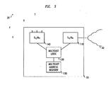
- that base station will be configured with more than one multicast IP address, one for each of those geographical areas (within IP v4 this is referred to as a "class D" address which is a type of IP address ranging from 224.0.0.0 to 239.255.255.255), and these addresses are stored in a multicast address register 130 at step 530.
- the base station then listens using transceiver logic 110 to alerts that may be sent over the IP network 40 from the alert controller 50 to all members of the multicast group associated with this multicast IP address.
- the base station joins the multicast groups (e.g. via internet group management protocol version 3, as defined in RFC 3376) and maintains its membership as long the base station remains in service.
- each base station belonging to different geographical areas may be configured with different multicast IP addresses so that the alert controller 50 can geographically scope the sending of alert messages.
- each base station may be configured with an alert area ID (or multiple alert area ID's), also stored in the multicast address register 130 and if the multicast message carrying the alert is not for any of these specific alert area ID's, then the base station may ignore that message.
- the assessment of the mapping of the coverage provided by base stations onto the geographical areas may be implemented at the base station level or may determined by the alert controller 50. In either event, the alert controller 50 maintains that mapping in the mapping table 90. If this assessment is not made by the alert controller 50, then the information is provided to the controller typically upon commissioning of each base station and entered into the mapping table 90. The information in the mapping table 90 may then be used subsequently when determining whether all necessary base stations have acknowledged receipt of an alert message intended for a particular region.
- the alert service agency sends 60 a message to the alert controller 50 which contain message content, as well as an indication of the geographical area or areas for delivery of that message.
- Some form of integrity protection will generally be necessary to authenticate the origin and integrity of the originating alert message.
- the management logic 95 will decode the indication of geographical area in the message and, at step S50, will determine the appropriate multicast IP addresses for the geographical areas specified in the originated alert message from the mapping table 90.
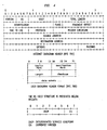
- the transceiver logic 70 then, at step S60, transmits the message over the IP network 40 to the base stations 30 to 30 N using each of those multicast IP addresses in accordance with the message format shown in Figure 4 .
- This message may optionally be encoded with one or more alert area IDs. Only those base stations which are configured to receive messages having those multicast IP addresses (and optionally the alert area IDs) will respond, the remaining base stations will ignore the messages.
- the message includes a source address and destination address.
- the source address is the alert controller 50 and the destination address is one of the multicast addresses.
- the source address will be the address of the base station and the destination address is the address of the alert controller 50.
- UDP user datagram protocol
- a port number may also be provided to indicate the message is an alert message.
- the differentiated services codepoint field is utilised to designate that the message is the highest priority possible.
- the payload will typically include a unique message identifier and optionally an indication that the message is intended only for particular user equipment and that the payload has been encoded in a particular manner which only the intended user equipment may decode.
- the base station On receipt of a multicast message having a multicast address to which the base station is subscribed, the base station will determine from a message identifier within the message payload whether that message content has been received by this base station previously and, if so may ignore the message even if it has been received using a different multicast address. Otherwise, the base station will acknowledge receipt of the message and perform a cell broadcast to all user equipment within its cell coverage area. The cell broadcast will contain the message content, together with an identifier identifying to the user equipment that this is an alert message. To account for transmission failures on the IP network from the base stations to the alert controller 50, the base stations may acknowledge receipt of a message previously received either with the same or different multicast address after receiving this repeated message a predetermined number of times.
- the user equipment On receipt of the message, the user equipment will identify the message as an alert message and provide an indication of this to the user.
- an indicator is included that the message is only intended for particular user equipment such as, for example, the emergency services, only user equipment preconfigured to decode such messages will display the alert.
- the controller will receive the acknowledgement message from the base station over the IP network 40 and indicate in the message status table 100 that the base station has acknowledged that message; the acknowledgement includes an IP address identifying the sending base station, together with the message identifier. Each different message sent will have been allocated a different message identifier and the base stations associated with the multicast addresses is derived from the mapping table 90. As the acknowledgement messages are received (irrespective of which multicast address the acknowledgement message is in response to), the base stations are indicated in the message status table 100. A determination is then made by the management logic 95, at step S70, of the base stations yet to respond and a decision is made on whether to transmit another multicast message or whether to transmit unicast messages to each of the outstanding base stations. At step S80, a message is returned to the alert service agency 60 indicated that the message has been delivered throughout the region, optionally together with an indication of those locations were the message could not be delivered.
- the alert controller 50 when the alert controller 50 receives a request to deliver an alert message to all base stations in a specific area, it sends this message to all base stations that need to receive this by sending it to all multicast IP addresses that are intended to cover the entire geographical region to be alerted. This is achieved by a protocol that encapsulates the alert message, the intended alert area ID's and a unique ID of the message, so that repetitions of the message (for resilience to transmission errors) can be detected. In this way, it can be seen that an alert message can be rapidly and efficiently targeted to specific geographical areas in a reliable and predictable manner.
Abstract
Description
- The present invention relates to a method of transmitting a message to user equipment within a telecommunications network, a controller operable to transmit a message to user equipment within a telecommunications network, a base station and a computer program product.
- It is often desired to transmit a message to many user equipment within a telecommunications network. For example, government agencies wish to communicate an alert warning of an impending emergency such as, for example, a tsunami, earthquake or other potential emergency, to user equipment within a telecommunications network in order to attempt to avert or mitigate the consequences of such a potentially catastrophic event.
- In a telecommunications network, such as that defined by the Third Generation Partnership Project (3GPP) in document S2-085143, it is envisaged that a cell broadcast entity (such as a government agency) sends an emergency broadcast request to a cell broadcast centre of a network operator. The cell broadcast centre utilises information within the emergency broadcast request to identify which mobility management entities need to be contacted. Those mobility management entities receive a distribute warning message request and reply with a distribute warning message response. Each mobility management entity then communicates with every base station by sending each base station a distribute warning message request. Each base station then responds by sending a distribute warning message response to the mobility management entity. The base stations then schedule the transmission of the warning message to user equipment.
- IMIELINSKI J NAVAS T: "RFC 2009: GPS-Based Addressing and Routing" GPS-BASED ADDRESSING AND ROUTING, XX, XX, 30 November 1996, pages 1-27, discloses a GPS-multicast routing scheme in which messages are routed from a sender to a mobile support station in which each partition and atom is mapped to a multicast address. Each mobile support station joins multicast groups for all partitions which intersect its range. Mobile support stations covering the target area of geographic mail should acknowledge those messages.
- ELAARAG H ET AL: "A reliable congestion control mechanism for geocasting in mobile wireless networks" INTERNATIONAL JOURNAL OF NETWORK MANAGEMENT, WILEY UK, vol. 13, no. 5, September 2003, pages 375-387, ISSN 1055-7148 discloses a congestion control mechanism for geocasting in mobile wireless networks. Multicast groups are generated, and if a host wants to receive a multicast message, it has to join a particular group first. Senders then multicast messages to this group. All the group members receive the message. Two acknowledgement aggregation methods are disclosed: in MAAM a single acknowledgement is sent to the sender from the base station; in MAAM/LR an optional caching mechanism is implemented in the base station to accommodate the different speeds of mobile hosts.
-
JP 2007 243718 -
US 2004/203562 discloses a cellular base station broadcast system. An emergency broadcast station generates a signal representing an emergency broadcast message that contains a frequency of an accessible main emergency channel at the emergency broadcast station and a priority level classifying the emergent or impendent disaster/related situation. The signal is transmitted to one or more base stations, each serving a plurality of users of the system, which in turn sends the signal to the users. The users tune to the frequency of the channel to receive the emergency broadcast message. - It is desired to provide an improved technique for transmitting messages to user equipment.
- According to a first aspect of the present invention, there is provided a method of transmitting a message to user equipment within a telecommunications network as claimed in
claim 1. - The first aspect recognises that messages, such as alert messages, may need to be delivered by the network to a plurality of base stations within a relatively short time period. Achieving such a short time period in an environment where control is highly centralised is difficult to achieve. This is because each message is transmitted to each base station sequentially and so if, for example, a controller (such as an mobility management entity) needs to communicate with a large number of base stations then this can take a long time. Furthermore, the first aspect also recognises that such message may be transmitted at a time when disruption may be occurring to the network or when the load on the network is high due to increases in traffic from user equipment as a result of any unfolding emergency. Accordingly, those sequential messages may take longer to transmit than usual and many retransmissions may be necessary to ensure that all base stations are communicated with.
- Accordingly, when a message is received to be transmitted to user equipment within a particular geographical area of the telecommunications network, one or more multicast internet protocol (IP) addresses are identified. These multicast IP addresses are identified as being associated with base stations which provide coverage within the particular geographical area. The message is then transmitted with the multicast IP address over the IP network to be received by base stations. In this way, each base station identified by the multicast IP address will simultaneously receive the message, rather than each individual base station needing to have its own dedicated message sent to each base station sequentially. It will be appreciated that this not only significantly speeds the time taken for identified base stations to receive the message, it also reduces the amount of traffic required since the message is transmitted in a multicast manner. Furthermore, only those base stations which are associated with the multicast IP address will act on the message, all other base stations may ignore it. Accordingly, this helps to ensure that the message is only relayed to user equipment in a particular geographical region, rather than being delivered to all user equipment supported by all base stations associated with a particular controller.
- In other words, when an message is received which is to be delivered to all the base stations within a specific area, the message is sent to all base stations that need to receive it by sending the message to all the multicast addresses that are intended to cover the entire geographical region to be alerted. This significantly reduces the number of message that need to be sent to the intended base stations in order for them to receive the message. For example, should a region including 3,000 base stations be affected, a unicast solution would be to send 3,000 messages (excluding retransmissions due to errors), one to each base station. In a multicast arrangement, it may sufficient to send a single, or typically no more than a few, messages to a single multicast address. It will appreciated that this reduces the amount of messages to be sent by orders of magnitude and enable tight time constraints on the delivery of messages to be achieved at an acceptable cost even in an architecture having highly centralised controllers.
- The list may include, for each message sent, an indication of each base station which has acknowledged receipt of that message. This information may be used to provide certainty that the message has been distributed within the geographical area or to identify potential areas of severe disruption.
- Given that an indication has been received of which bas stations are associated with a particular multicast IP address, and a list is generated of those base stations which have acknowledged the multicast message, it is possible to therefore determine those base stations which have not acknowledged receipt of that multicast message. This information may be used to identify areas where base stations cannot be communicated with and/or to identify those base stations to which the message may need to be retransmitted.
- A determination can be made of whether it would be more efficient to retransmit the multicast message to all base stations or whether it would be more efficient to perform a conventional unicast transmission to the outstanding base stations.
- In one embodiment, the method comprises the step of: allocating unique multicast IP addresses to be associated with predefined geographical areas. Accordingly, each particular different geographical area or region is associated with a unique multicast IP address. This helps to ensure that any messages intended for those geographical regions can be efficiently routed. It will be appreciated that these geographical regions may overlap or be sub-regions of another geographical region. Typically, these geographical regions will be defined by a requesting authority, such as a government agency.
- In one embodiment, the method comprises the step of: receiving an indication of each multicast IP address associated with each base station. By receiving an indication of which multicast IP addresses are associated with each base station, it is possible to determine which base stations are associated with each geographical region. It will be appreciated that base stations will typically be associated with more than one geographical region and will therefore be associated with more than one multicast IP address.
- In one embodiment, the step of identifying comprises: identifying a plurality of multicast IP addresses designated as being associated with base stations providing coverage within the predefined geographical area; and the step of transmitting comprises transmitting the message content within a plurality of multicast messages, each using a corresponding one of the plurality of multicast IP addresses. Accordingly, where the geographical area is not covered by a single multicast address, multiple multicast IP addresses may be identified to provide the necessary coverage within the geographical area. The message is then sent using each of those multicast IP addresses.
- In one embodiment, the method comprises the step of: for each message received having message content to be transmitted to user equipment within a predefined geographical area of the telecommunications network, allocating a unique message identifier to be transmitted with the message content. Accordingly, a message identifier may be used. This message identifier may be utilised by, for example, a base station to enable that base station to ignore any repeated multicast message which it has previously received.
- In one embodiment, the step of transmitting comprises: transmitting the message identifier within each multicast message, each message identifier uniquely identifying different message content. Accordingly, each multi cast message may be transmitted with the message identifier.
- In one embodiment, the method comprises the step of: maintaining a list of those base stations which have acknowledged receipt of at least one the plurality of multicast messages by determining whether at least one acknowledgement message incorporating the message identifier has been received from those base stations. It may that the same base station will be associated with a number of different multicast IP addresses. Should the same message be received by a base station on each of those different multicast IP addresses then the base station may only acknowledge and act upon one of these message in order to reduce traffic load on the network. Hence, should an acknowledgement be received which includes the identifier, then it can be assumed that the base station has received the message over at least one of the multiple different multicast IP addresses associated with that base station. Hence, it can be deduced that there is no necessity to retransmit the message even though no response.has been received for every multicast IP address messages.
- In one embodiment, the step of transmitting comprises: transmitting a priority identifier within each multicast message to indicate that the multicast message it to be transmitted with a highest possible priority. Accordingly, the multicast messages take priority over all other traffic in the network to ensure that they are delivered as quickly as possible.
- In one embodiment, the step of transmitting comprises: transmitting a transmission identifier within each multicast message to indicate that the message content is to be transmitted by recipient base stations within a cell broadcast message. Accordingly, the message may contain an indication to the base stations that the message that has been received it to be broadcast throughout its cell to all user equipment in accordance with whichever particular technique is utilised within that network environment. Again, it will be appreciated that this helps to ensure that this message is delivered by the base stations to active user equipment as quickly as possible.
- According to a second aspect of the present invention, there is provided a computer program product operable, when executed on a computer, to perform the method steps of the first aspect.
- According to a third aspect of the present invention, there is provided a controller operable to transmit a message to user equipment within a telecommunications network as claimed in claim 11.
- In one embodiment, the multicast address logic is operable to allocate unique multicast IP addresses to be associated with predefined geographical areas.
- In one embodiment, the multicast address logic is operable to receive an indication of each multicast IP address associated with each base station.
- In one embodiment, the multicast address logic is operable to identify a plurality of multicast IP addresses designated as being associated with base stations providing coverage within the predefined geographical area; and the transmission logic is operable to transmit the message content within a plurality of multicast messages, each using a corresponding one of the plurality of multicast IP addresses.
- In one embodiment, the multicast address logic is operable, for each message received having message content to be transmitted to user equipment within a predefined geographical area of the telecommunications network, to allocate a unique message identifier to be transmitted with the message content.
- In one embodiment, the transmission logic is operable to transmit the message identifier within each multicast message, each message identifier uniquely identifying different message content.
- In one embodiment, the multicast address logic is operable to maintain a list of those base stations which have acknowledged receipt of at least one the plurality of multicast messages by determining whether at least one acknowledgement message incorporating the message identifier has been received from those base stations.
- In one embodiment, the transmission logic is operable to transmit a priority identifier within each multicast message to indicate that the multicast message it to be transmitted with a highest possible priority.
- In one embodiment, the transmission logic is operable to transmit a transmission identifier within each multicast message to indicate that the message content is to be transmitted by recipient base stations within a cell broadcast message.
- Further particular and preferred aspects of the present invention are set out in the accompanying independent and dependent claims. Features of the dependent claims may be combined with features of the independent claims as appropriate, and in combinations other than those explicitly set out in the claims.
- Embodiments of the present invention will now be described further, with reference to the accompanying drawings, in which:
-
Figure 1 illustrates a telecommunications network according to one embodiment; -
Figure 2 illustrates the main features of the controller illustrated inFigure 1 ; -
Figure 3 illustrates the main features of a base station illustrated inFigure 1 ; -
Figure 4 illustrates the format of the multicast messages transmitted through the IP network shown inFigure 1 ; and -
Figure 5 is a flow chart illustrating the main processing steps of the controller illustrated inFigure 2 . -
Figures 1 to 3 illustrates the main components of a telecommunications network, generally 10, accordingly to one embodiment. As shown inFigure 1 ,user equipment 20 roam through thetelecommunications network 10.Base stations 301 to 30N are provided which support respective cells. A number ofsuch base stations 301 to 30N are provided, which are distributed geographically in order to provide a wide area of wireless communications coverage to theuser equipment 20. Whenuser equipment 20 is within a cell supported by abase station 301 to 30N then communications may be established between theuser equipment 20 and thatbase station 301 to 30N over an associated radio link. Eachbase station 301 to 30N supports a number of sectors within each cell. Typically, a different antenna within abase station 301 to 30N supports an associated sector. Accordingly, eachbase station 301 to 30N has multiple antennas and signals sent through the different antennas are electronically weighted to provide this sectorised approach. Of course, it will be appreciated thatFigure 1 illustrates a small subset of the total number ofuser equipment 20 andbase stations 301 to 30N that may be present in a typical communications network. - Each
base station 30l to 30N communicates over abackhaul IP network 40 with analert controller 50. In this arrangement, thealert controller 50 is a separate, dedicated controller but it will be appreciated that this functionality may be provided within an existing controller within thetelecommunications network 10. - As shown in
Figure 2 , thealert controller 50 receives messages from analert service agency 60 such as, for example, a government agency at thetransceiver logic 80 and distributes these messages using thetransceiver logic 70 as multicast transmissions over thebackhaul IP network 40 to the relevant base stations for onward transmission touser equipment 20 supported by those base stations. The main steps of taken to perform this operation are described inFigure 5 . - At step S10, the
alert service agency 60 will define predefined geographical areas to which they may require alert messages to be sent. At step S20, thecontroller 50 allocates a multicast IP address to each of those predefined geographical areas and maintains this mapping in a mapping table 90. When commissioning each of thebase stations 301 to 30N their geographical location is known, as is the geographical coverage provided by that base stations touser equipment 20. Accordingly, an assessment of which geographical areas each base station will provide coverage within can be made. The base station is configured to receive multicast messages having multicast IP addresses for each of those geographical areas. For example, thealert service agency 60 may set geographical areas at country, county and city levels. In addition, the alert service agency may set geographical areas based on other criteria such as, for example, flood regions, coastal areas, earthquake zones, avalanche areas and the like. Likewise, the messages may only be intended for particular groups within these geographical areas such as, for example, a particular emergency service or government agency. A base station within a city will provide coverage within the predefined country, county and city geographical areas and possibly areas defined by other criteria. Therefore, as shown inFigure 3 , that base station will be configured with more than one multicast IP address, one for each of those geographical areas (within IP v4 this is referred to as a "class D" address which is a type of IP address ranging from 224.0.0.0 to 239.255.255.255), and these addresses are stored in amulticast address register 130 at step 530. The base station then listens usingtransceiver logic 110 to alerts that may be sent over theIP network 40 from thealert controller 50 to all members of the multicast group associated with this multicast IP address. The base station joins the multicast groups (e.g. via internet groupmanagement protocol version 3, as defined in RFC 3376) and maintains its membership as long the base station remains in service. As mentioned previously, base stations belonging to different geographical areas may be configured with different multicast IP addresses so that thealert controller 50 can geographically scope the sending of alert messages. In addition, each base station may be configured with an alert area ID (or multiple alert area ID's), also stored in themulticast address register 130 and if the multicast message carrying the alert is not for any of these specific alert area ID's, then the base station may ignore that message. - The assessment of the mapping of the coverage provided by base stations onto the geographical areas may be implemented at the base station level or may determined by the
alert controller 50. In either event, thealert controller 50 maintains that mapping in the mapping table 90. If this assessment is not made by thealert controller 50, then the information is provided to the controller typically upon commissioning of each base station and entered into the mapping table 90. The information in the mapping table 90 may then be used subsequently when determining whether all necessary base stations have acknowledged receipt of an alert message intended for a particular region. - At step S40, when an alert situation occurs, the alert service agency sends 60 a message to the
alert controller 50 which contain message content, as well as an indication of the geographical area or areas for delivery of that message. Some form of integrity protection will generally be necessary to authenticate the origin and integrity of the originating alert message. - The
management logic 95 will decode the indication of geographical area in the message and, at step S50, will determine the appropriate multicast IP addresses for the geographical areas specified in the originated alert message from the mapping table 90. Thetransceiver logic 70 then, at step S60, transmits the message over theIP network 40 to thebase stations 30 to 30N using each of those multicast IP addresses in accordance with the message format shown inFigure 4 . This message may optionally be encoded with one or more alert area IDs. Only those base stations which are configured to receive messages having those multicast IP addresses (and optionally the alert area IDs) will respond, the remaining base stations will ignore the messages. - As shown in
Figure 4 , the message includes a source address and destination address. For outgoing messages, the source address is thealert controller 50 and the destination address is one of the multicast addresses. For acknowledgement messages, the source address will be the address of the base station and the destination address is the address of thealert controller 50. For user datagram protocol (UDP) messages, a port number may also be provided to indicate the message is an alert message. The differentiated services codepoint field is utilised to designate that the message is the highest priority possible. The payload will typically include a unique message identifier and optionally an indication that the message is intended only for particular user equipment and that the payload has been encoded in a particular manner which only the intended user equipment may decode. - On receipt of a multicast message having a multicast address to which the base station is subscribed, the base station will determine from a message identifier within the message payload whether that message content has been received by this base station previously and, if so may ignore the message even if it has been received using a different multicast address. Otherwise, the base station will acknowledge receipt of the message and perform a cell broadcast to all user equipment within its cell coverage area. The cell broadcast will contain the message content, together with an identifier identifying to the user equipment that this is an alert message. To account for transmission failures on the IP network from the base stations to the
alert controller 50, the base stations may acknowledge receipt of a message previously received either with the same or different multicast address after receiving this repeated message a predetermined number of times. - On receipt of the message, the user equipment will identify the message as an alert message and provide an indication of this to the user. Optionally, where an indicator is included that the message is only intended for particular user equipment such as, for example, the emergency services, only user equipment preconfigured to decode such messages will display the alert.
- The controller will receive the acknowledgement message from the base station over the
IP network 40 and indicate in the message status table 100 that the base station has acknowledged that message; the acknowledgement includes an IP address identifying the sending base station, together with the message identifier. Each different message sent will have been allocated a different message identifier and the base stations associated with the multicast addresses is derived from the mapping table 90. As the acknowledgement messages are received (irrespective of which multicast address the acknowledgement message is in response to), the base stations are indicated in the message status table 100. A determination is then made by themanagement logic 95, at step S70, of the base stations yet to respond and a decision is made on whether to transmit another multicast message or whether to transmit unicast messages to each of the outstanding base stations. At step S80, a message is returned to thealert service agency 60 indicated that the message has been delivered throughout the region, optionally together with an indication of those locations were the message could not be delivered. - Hence, it can be seen that when the
alert controller 50 receives a request to deliver an alert message to all base stations in a specific area, it sends this message to all base stations that need to receive this by sending it to all multicast IP addresses that are intended to cover the entire geographical region to be alerted. This is achieved by a protocol that encapsulates the alert message, the intended alert area ID's and a unique ID of the message, so that repetitions of the message (for resilience to transmission errors) can be detected. In this way, it can be seen that an alert message can be rapidly and efficiently targeted to specific geographical areas in a reliable and predictable manner. - Although illustrative embodiments of the invention have been disclosed in detail herein, with reference to the accompanying drawings, it is understood that the invention is not limited to the precise embodiment shown and that various changes and modifications can be effected therein by one skilled in the art without departing from the scope of the invention as defined by the appended claims
Claims (11)
- A method of transmitting a message to user equipment (20) within a telecommunications network (10), said method comprising the steps of:receiving (S40) a message having message content to be transmitted to user equipment within a predefined geographical area of said telecommunications network;identifying (S50) at least one multicast IP address designated as being associated with base stations (301- 30n) providing telecommunications coverage with user equipment within said predefined geographical area;transmitting (S60) said message content within at least one multicast message, each multicast message using a corresponding one of said at least one multicast IP address, over an IP network to base stations providing telecommunications coverage within said predetermined geographical area for onward transmission to user equipment; characterised by further comprising the following steps :maintaining a list of those base stations which have acknowledged receipt of said at least one multicast message;determining (S70) those base stations yet to acknowledge receipt of said at least one multicast message; andin the event that, after a predetermined period of time, those base stations yet to acknowledge receipt of said at least one multicast message exceeds a predetermined threshold number, determining whether to retransmit said at least one multicast message or to transmit a unicast message to each of those base stations determined as yet to acknowledge receipt of said at least one multicast message.
- The method of claim 1, comprising the step of:allocating (S20) unique multicast IP addresses to be associated with predefined geographical areas.
- The method of claim 2, comprising the step of:receiving an indication of each multicast IP address associated with each base station.
- The method of claim 1, wherein said step of identifying comprises:identifying a plurality of multicast IP addresses designated as being associated with base stations providing coverage within said predefined geographical area; and said step of transmitting comprises transmitting said message content within a plurality of multicast messages, each using a corresponding one of said plurality of multicast IP addresses.
- The method of claim 1, comprising the step of:for each message received having message content to be transmitted to user equipment within a predefined geographical area of said telecommunications network, allocating a unique message identifier to be transmitted with said message content.
- The method of claim 5, wherein said step of transmitting comprises:transmitting said message identifier within each multicast message, each message identifier uniquely identifying different message content.
- The method of claim 6, comprising the step of:maintaining a list of those base stations which have acknowledged receipt of at least one said plurality of multicast messages by determining whether at least one acknowledgement message incorporating said message identifier has been received from those base stations.
- The method of claim 1, wherein said step of transmitting comprises:transmitting a priority identifier within each multicast message to indicate that said multicast message it to be transmitted with a highest possible priority.
- The method of claim 1, wherein said step of transmitting comprises:transmitting a transmission identifier within each multicast message to indicate that said message content is to be transmitted by recipient base stations within a cell broadcast message.
- A computer program product comprising means operable, when executed on a computer, to perform all the method steps of claim 1.
- A controller (50) operable to transmit a message to user equipment (20) within a telecommunications network (10), said controller comprising:reception logic (80) operable to receive a message having message content to be transmitted to user equipment within a predefined geographical area of said telecommunications network;multicast address logic (90, 95) operable to identify at least one multicast IP address designated as being associated with base stations (301- 30n) providing telecommunications coverage with user equipment within said predefined geographical area; andtransmission logic (70) operable to transmit said message content within at least one multicast message, each multicast message using a corresponding one of said at least one multicast IP address, over an IP network to base stations providing telecommunications coverage within said predetermined geographical area for onward transmission to user equipment, characterized in that said multicast address logic is operable to maintain a list of those base stations which have acknowledged receipt of said at least one multicast message, to determine those base stations yet to acknowledge receipt of said at least one multicast message, and in the event that, after a predetermined period of time, those base stations yet to acknowledge receipt of said at least one multicast message exceeds a predetermined threshold number, to determine whether cause said transmission logic to retransmit said at least one multicast message or to transmit a unicast message to each of those base stations determined as yet to acknowledge receipt of said at least one multicast message.
Priority Applications (5)
| Application Number | Priority Date | Filing Date | Title |
|---|---|---|---|
| AT09360001T ATE519290T1 (en) | 2009-01-05 | 2009-01-05 | MESSAGE TRANSMISSION |
| EP09360001A EP2204946B1 (en) | 2009-01-05 | 2009-01-05 | Message transmission |
| US13/143,252 US20120023178A1 (en) | 2009-01-05 | 2009-12-31 | Message transmission |
| CN200980153757.1A CN102273130B (en) | 2009-01-05 | 2009-12-31 | Message transmission |
| PCT/EP2009/009353 WO2010076039A1 (en) | 2009-01-05 | 2009-12-31 | Message transmission |
Applications Claiming Priority (1)
| Application Number | Priority Date | Filing Date | Title |
|---|---|---|---|
| EP09360001A EP2204946B1 (en) | 2009-01-05 | 2009-01-05 | Message transmission |
Publications (2)
| Publication Number | Publication Date |
|---|---|
| EP2204946A1 EP2204946A1 (en) | 2010-07-07 |
| EP2204946B1 true EP2204946B1 (en) | 2011-08-03 |
Family
ID=40637087
Family Applications (1)
| Application Number | Title | Priority Date | Filing Date |
|---|---|---|---|
| EP09360001A Active EP2204946B1 (en) | 2009-01-05 | 2009-01-05 | Message transmission |
Country Status (5)
| Country | Link |
|---|---|
| US (1) | US20120023178A1 (en) |
| EP (1) | EP2204946B1 (en) |
| CN (1) | CN102273130B (en) |
| AT (1) | ATE519290T1 (en) |
| WO (1) | WO2010076039A1 (en) |
Families Citing this family (19)
| Publication number | Priority date | Publication date | Assignee | Title |
|---|---|---|---|---|
| JP5471707B2 (en) * | 2010-03-29 | 2014-04-16 | 富士通株式会社 | Base station apparatus and multicast signal distribution method |
| US9116223B1 (en) | 2010-06-03 | 2015-08-25 | 8X8, Inc. | Systems, methods, devices and arrangements for emergency call services and user participation incentives |
| US8879540B1 (en) | 2010-06-03 | 2014-11-04 | 8X8, Inc. | Systems, methods, devices and arrangements for emergency call services |
| US9689988B1 (en) | 2010-06-03 | 2017-06-27 | 8X8, Inc. | Systems, methods, devices and arrangements for emergency call services and emergency broadcasts |
| US9002957B2 (en) * | 2011-04-27 | 2015-04-07 | Verizon Patent And Licensing Inc. | Profile message communications |
| CN103037418B (en) * | 2011-09-30 | 2016-03-30 | 华为技术有限公司 | A kind of methods, devices and systems realizing alarm event process |
| US10044482B2 (en) * | 2011-10-31 | 2018-08-07 | Fraunhofer-Gesellschaft zur Förderung der angewandten Forschung e.V. | Apparatus and method for transmitting a message to multiple receivers |
| JP2013197909A (en) * | 2012-03-21 | 2013-09-30 | Ricoh Co Ltd | Radio communication method and radio communication system |
| WO2014010102A1 (en) * | 2012-07-13 | 2014-01-16 | Telefonaktiebolaget L M Ericsson (Publ) | Technique for distributing a message to mobile terminals that are located in a destination area |
| US9609488B2 (en) * | 2013-02-01 | 2017-03-28 | Qualcomm Incorporated | Managing broadcast services |
| US9787579B2 (en) | 2015-04-06 | 2017-10-10 | Verizon Digital Media Services Inc. | Application controlled path selection based on type-of-service |
| US9736059B2 (en) | 2015-04-06 | 2017-08-15 | Verizon Digital Media Services Inc. | Purging failover through application controlled transit selection |
| US10033628B2 (en) | 2015-04-06 | 2018-07-24 | Verizon Digital Media Services Inc. | Application controlled path selection over different transit providers |
| EP3160168B1 (en) * | 2015-10-23 | 2019-12-11 | Vodafone Holding GmbH | Ip multicast for geomessaging |
| US11076051B1 (en) | 2016-05-04 | 2021-07-27 | 8X8, Inc. | Endpoint location update control for call routing decisions |
| US10326888B1 (en) | 2016-05-04 | 2019-06-18 | 8X8, Inc. | Location updates for call routing decisions |
| US10542150B1 (en) | 2016-05-04 | 2020-01-21 | 8X8, Inc. | Server generated timing of location updates for call routing decisions |
| US10530934B1 (en) | 2016-05-04 | 2020-01-07 | 8X8, Inc. | Endpoint location determination for call routing decisions |
| US11115369B1 (en) | 2020-07-29 | 2021-09-07 | Motorola Solutions, Inc. | Transmitting near real-time geographic mass messaging requests |
Family Cites Families (12)
| Publication number | Priority date | Publication date | Assignee | Title |
|---|---|---|---|---|
| US6853627B1 (en) * | 2000-04-19 | 2005-02-08 | Telefonaktiebolaget Lm Ericsson (Publ) | Method, system and radio base station for paging a mobile station in a third generation general packet radio service (GPRS) network |
| US6633765B1 (en) * | 2000-08-28 | 2003-10-14 | Qualcomm, Incorporated | Method and apparatus for performing coverage control for multicast services in a wireless network |
| WO2003021838A2 (en) * | 2001-08-28 | 2003-03-13 | Telefonaktiebolaget Lm Ericsson (Publ) | Multicast group management in telecommunication networks |
| US7039386B2 (en) | 2002-04-18 | 2006-05-02 | Lucent Technologies Inc. | Cellular base station broadcast method and system |
| US7613467B2 (en) * | 2003-10-31 | 2009-11-03 | The Boeing Company | Geo-cast systems and methods |
| US8095958B2 (en) * | 2004-06-29 | 2012-01-10 | Nokia Corporation | System and method for location-appropriate service listings |
| US20050289592A1 (en) * | 2004-06-29 | 2005-12-29 | Larri Vermola | System and method for service listings |
| US8059625B2 (en) * | 2006-02-03 | 2011-11-15 | Motorola Mobility, Inc. | Distributed architecture and methods for broadcast/multicast service |
| JP2007243718A (en) | 2006-03-09 | 2007-09-20 | Matsushita Electric Ind Co Ltd | Hand-over control method, connection station, and radio base station |
| CN101132607B (en) * | 2006-08-22 | 2011-07-20 | 上海贝尔阿尔卡特股份有限公司 | Access gateway, base station and method for evolutionary multimedia broadcast multicast business |
| US8532011B2 (en) * | 2007-09-24 | 2013-09-10 | Qualcomm Incorporated | Method and apparatus for transmitting multiple multicast communications over a wireless communication network |
| US20090291630A1 (en) * | 2008-03-17 | 2009-11-26 | Dunn Timothy N | Geographic targeting of alerts |
-
2009
- 2009-01-05 AT AT09360001T patent/ATE519290T1/en not_active IP Right Cessation
- 2009-01-05 EP EP09360001A patent/EP2204946B1/en active Active
- 2009-12-31 WO PCT/EP2009/009353 patent/WO2010076039A1/en active Application Filing
- 2009-12-31 US US13/143,252 patent/US20120023178A1/en not_active Abandoned
- 2009-12-31 CN CN200980153757.1A patent/CN102273130B/en active Active
Also Published As
| Publication number | Publication date |
|---|---|
| EP2204946A1 (en) | 2010-07-07 |
| ATE519290T1 (en) | 2011-08-15 |
| WO2010076039A1 (en) | 2010-07-08 |
| CN102273130A (en) | 2011-12-07 |
| US20120023178A1 (en) | 2012-01-26 |
| CN102273130B (en) | 2014-01-15 |
Similar Documents
| Publication | Publication Date | Title |
|---|---|---|
| EP2204946B1 (en) | Message transmission | |
| US10743154B2 (en) | Method and apparatus for forwarding vehicle to everything service | |
| EP2342907B1 (en) | Emergency notification method and a node | |
| KR101314693B1 (en) | Emergency information reporting system | |
| US20090227224A1 (en) | Determining wireless system availability using emergency alert system messaging | |
| US11937198B2 (en) | 5G delay tolerant data services | |
| US20150111522A1 (en) | Geo-Redundant and High Reliability Commercial Mobile Alert System (CMAS) | |
| US9521514B2 (en) | Method and apparatus for controlling network access in a wireless communication system | |
| CN106358239B (en) | Data transmission method, sending equipment and receiving equipment | |
| GB2439373A (en) | A Method for Network Edge Device Selection | |
| KR101533137B1 (en) | Localized information service | |
| KR20010098482A (en) | Retransmission control method, information delivery apparatus and radio terminal in multicast service providing system | |
| US20150078241A1 (en) | Method and apparatus for supporting multicast delivery | |
| US20120039314A1 (en) | Method and apparatus of supporting wireless femtocell clusters | |
| KR20080112144A (en) | Data transmission/ receiving method in multimedia broadcast multicast service system and apparatus thereof | |
| Maia et al. | A rate control video dissemination solution for extremely dynamic vehicular ad hoc networks | |
| US20220078883A1 (en) | Public warning system enhancement | |
| EP2385743B1 (en) | Method, system and drnc for transporting cell capacity by crossing iur interface | |
| WO2018222343A1 (en) | Auxiliary receivers for qos balancing in wireless communications | |
| CN113169938B (en) | Method for multi-channel discovery with partially disjoint paths | |
| Hwang et al. | Beyond vision: Hidden car detector with on-demand relaying in vehicular communications | |
| WO2002102099A2 (en) | Transmission of a sms cell broadcast message in a cellular communications network infrastructure | |
| US20230247518A1 (en) | Addressing of D2D Transmissions by Target Geographical Area | |
| WO2023042271A1 (en) | Terminal device, route selection method, control circuit, and storage medium | |
| WO2022024945A1 (en) | Communication control method |
Legal Events
| Date | Code | Title | Description |
|---|---|---|---|
| PUAI | Public reference made under article 153(3) epc to a published international application that has entered the european phase |
Free format text: ORIGINAL CODE: 0009012 |
|
| AK | Designated contracting states |
Kind code of ref document: A1 Designated state(s): AT BE BG CH CY CZ DE DK EE ES FI FR GB GR HR HU IE IS IT LI LT LU LV MC MK MT NL NO PL PT RO SE SI SK TR |
|
| AX | Request for extension of the european patent |
Extension state: AL BA RS |
|
| 17P | Request for examination filed |
Effective date: 20110107 |
|
| GRAP | Despatch of communication of intention to grant a patent |
Free format text: ORIGINAL CODE: EPIDOSNIGR1 |
|
| RIC1 | Information provided on ipc code assigned before grant |
Ipc: H04L 12/18 20060101AFI20110202BHEP |
|
| AKX | Designation fees paid |
Designated state(s): AT BE BG CH CY CZ DE DK EE ES FI FR GB GR HR HU IE IS IT LI LT LU LV MC MK MT NL NO PL PT RO SE SI SK TR |
|
| GRAS | Grant fee paid |
Free format text: ORIGINAL CODE: EPIDOSNIGR3 |
|
| GRAA | (expected) grant |
Free format text: ORIGINAL CODE: 0009210 |
|
| AK | Designated contracting states |
Kind code of ref document: B1 Designated state(s): AT BE BG CH CY CZ DE DK EE ES FI FR GB GR HR HU IE IS IT LI LT LU LV MC MK MT NL NO PL PT RO SE SI SK TR |
|
| REG | Reference to a national code |
Ref country code: GB Ref legal event code: FG4D |
|
| REG | Reference to a national code |
Ref country code: CH Ref legal event code: EP |
|
| REG | Reference to a national code |
Ref country code: IE Ref legal event code: FG4D |
|
| REG | Reference to a national code |
Ref country code: DE Ref legal event code: R096 Ref document number: 602009001995 Country of ref document: DE Effective date: 20111006 |
|
| REG | Reference to a national code |
Ref country code: NL Ref legal event code: VDEP Effective date: 20110803 |
|
| LTIE | Lt: invalidation of european patent or patent extension |
Effective date: 20110803 |
|
| PG25 | Lapsed in a contracting state [announced via postgrant information from national office to epo] |
Ref country code: LT Free format text: LAPSE BECAUSE OF FAILURE TO SUBMIT A TRANSLATION OF THE DESCRIPTION OR TO PAY THE FEE WITHIN THE PRESCRIBED TIME-LIMIT Effective date: 20110803 Ref country code: PT Free format text: LAPSE BECAUSE OF FAILURE TO SUBMIT A TRANSLATION OF THE DESCRIPTION OR TO PAY THE FEE WITHIN THE PRESCRIBED TIME-LIMIT Effective date: 20111205 Ref country code: HR Free format text: LAPSE BECAUSE OF FAILURE TO SUBMIT A TRANSLATION OF THE DESCRIPTION OR TO PAY THE FEE WITHIN THE PRESCRIBED TIME-LIMIT Effective date: 20110803 Ref country code: IS Free format text: LAPSE BECAUSE OF FAILURE TO SUBMIT A TRANSLATION OF THE DESCRIPTION OR TO PAY THE FEE WITHIN THE PRESCRIBED TIME-LIMIT Effective date: 20111203 Ref country code: SE Free format text: LAPSE BECAUSE OF FAILURE TO SUBMIT A TRANSLATION OF THE DESCRIPTION OR TO PAY THE FEE WITHIN THE PRESCRIBED TIME-LIMIT Effective date: 20110803 Ref country code: FI Free format text: LAPSE BECAUSE OF FAILURE TO SUBMIT A TRANSLATION OF THE DESCRIPTION OR TO PAY THE FEE WITHIN THE PRESCRIBED TIME-LIMIT Effective date: 20110803 Ref country code: NO Free format text: LAPSE BECAUSE OF FAILURE TO SUBMIT A TRANSLATION OF THE DESCRIPTION OR TO PAY THE FEE WITHIN THE PRESCRIBED TIME-LIMIT Effective date: 20111103 Ref country code: NL Free format text: LAPSE BECAUSE OF FAILURE TO SUBMIT A TRANSLATION OF THE DESCRIPTION OR TO PAY THE FEE WITHIN THE PRESCRIBED TIME-LIMIT Effective date: 20110803 |
|
| REG | Reference to a national code |
Ref country code: AT Ref legal event code: MK05 Ref document number: 519290 Country of ref document: AT Kind code of ref document: T Effective date: 20110803 |
|
| RAP2 | Party data changed (patent owner data changed or rights of a patent transferred) |
Owner name: ALCATEL LUCENT |
|
| PG25 | Lapsed in a contracting state [announced via postgrant information from national office to epo] |
Ref country code: AT Free format text: LAPSE BECAUSE OF FAILURE TO SUBMIT A TRANSLATION OF THE DESCRIPTION OR TO PAY THE FEE WITHIN THE PRESCRIBED TIME-LIMIT Effective date: 20110803 Ref country code: CY Free format text: LAPSE BECAUSE OF FAILURE TO SUBMIT A TRANSLATION OF THE DESCRIPTION OR TO PAY THE FEE WITHIN THE PRESCRIBED TIME-LIMIT Effective date: 20110803 Ref country code: PL Free format text: LAPSE BECAUSE OF FAILURE TO SUBMIT A TRANSLATION OF THE DESCRIPTION OR TO PAY THE FEE WITHIN THE PRESCRIBED TIME-LIMIT Effective date: 20110803 Ref country code: LV Free format text: LAPSE BECAUSE OF FAILURE TO SUBMIT A TRANSLATION OF THE DESCRIPTION OR TO PAY THE FEE WITHIN THE PRESCRIBED TIME-LIMIT Effective date: 20110803 Ref country code: SI Free format text: LAPSE BECAUSE OF FAILURE TO SUBMIT A TRANSLATION OF THE DESCRIPTION OR TO PAY THE FEE WITHIN THE PRESCRIBED TIME-LIMIT Effective date: 20110803 Ref country code: GR Free format text: LAPSE BECAUSE OF FAILURE TO SUBMIT A TRANSLATION OF THE DESCRIPTION OR TO PAY THE FEE WITHIN THE PRESCRIBED TIME-LIMIT Effective date: 20111104 |
|
| REG | Reference to a national code |
Ref country code: CH Ref legal event code: PCOW Free format text: ALCATEL LUCENT;3, AVENUE OCTAVE GREARD;75007 PARIS (FR) |
|
| PG25 | Lapsed in a contracting state [announced via postgrant information from national office to epo] |
Ref country code: BE Free format text: LAPSE BECAUSE OF FAILURE TO SUBMIT A TRANSLATION OF THE DESCRIPTION OR TO PAY THE FEE WITHIN THE PRESCRIBED TIME-LIMIT Effective date: 20110803 |
|
| PG25 | Lapsed in a contracting state [announced via postgrant information from national office to epo] |
Ref country code: CZ Free format text: LAPSE BECAUSE OF FAILURE TO SUBMIT A TRANSLATION OF THE DESCRIPTION OR TO PAY THE FEE WITHIN THE PRESCRIBED TIME-LIMIT Effective date: 20110803 Ref country code: SK Free format text: LAPSE BECAUSE OF FAILURE TO SUBMIT A TRANSLATION OF THE DESCRIPTION OR TO PAY THE FEE WITHIN THE PRESCRIBED TIME-LIMIT Effective date: 20110803 |
|
| PG25 | Lapsed in a contracting state [announced via postgrant information from national office to epo] |
Ref country code: EE Free format text: LAPSE BECAUSE OF FAILURE TO SUBMIT A TRANSLATION OF THE DESCRIPTION OR TO PAY THE FEE WITHIN THE PRESCRIBED TIME-LIMIT Effective date: 20110803 Ref country code: RO Free format text: LAPSE BECAUSE OF FAILURE TO SUBMIT A TRANSLATION OF THE DESCRIPTION OR TO PAY THE FEE WITHIN THE PRESCRIBED TIME-LIMIT Effective date: 20110803 Ref country code: IT Free format text: LAPSE BECAUSE OF FAILURE TO SUBMIT A TRANSLATION OF THE DESCRIPTION OR TO PAY THE FEE WITHIN THE PRESCRIBED TIME-LIMIT Effective date: 20110803 |
|
| PLBE | No opposition filed within time limit |
Free format text: ORIGINAL CODE: 0009261 |
|
| STAA | Information on the status of an ep patent application or granted ep patent |
Free format text: STATUS: NO OPPOSITION FILED WITHIN TIME LIMIT |
|
| PG25 | Lapsed in a contracting state [announced via postgrant information from national office to epo] |
Ref country code: DK Free format text: LAPSE BECAUSE OF FAILURE TO SUBMIT A TRANSLATION OF THE DESCRIPTION OR TO PAY THE FEE WITHIN THE PRESCRIBED TIME-LIMIT Effective date: 20110803 |
|
| 26N | No opposition filed |
Effective date: 20120504 |
|
| REG | Reference to a national code |
Ref country code: DE Ref legal event code: R097 Ref document number: 602009001995 Country of ref document: DE Effective date: 20120504 |
|
| PG25 | Lapsed in a contracting state [announced via postgrant information from national office to epo] |
Ref country code: MC Free format text: LAPSE BECAUSE OF NON-PAYMENT OF DUE FEES Effective date: 20120131 |
|
| REG | Reference to a national code |
Ref country code: IE Ref legal event code: MM4A |
|
| PG25 | Lapsed in a contracting state [announced via postgrant information from national office to epo] |
Ref country code: IE Free format text: LAPSE BECAUSE OF NON-PAYMENT OF DUE FEES Effective date: 20120105 |
|
| PG25 | Lapsed in a contracting state [announced via postgrant information from national office to epo] |
Ref country code: MK Free format text: LAPSE BECAUSE OF FAILURE TO SUBMIT A TRANSLATION OF THE DESCRIPTION OR TO PAY THE FEE WITHIN THE PRESCRIBED TIME-LIMIT Effective date: 20110803 |
|
| PG25 | Lapsed in a contracting state [announced via postgrant information from national office to epo] |
Ref country code: ES Free format text: LAPSE BECAUSE OF FAILURE TO SUBMIT A TRANSLATION OF THE DESCRIPTION OR TO PAY THE FEE WITHIN THE PRESCRIBED TIME-LIMIT Effective date: 20111114 |
|
| PG25 | Lapsed in a contracting state [announced via postgrant information from national office to epo] |
Ref country code: BG Free format text: LAPSE BECAUSE OF FAILURE TO SUBMIT A TRANSLATION OF THE DESCRIPTION OR TO PAY THE FEE WITHIN THE PRESCRIBED TIME-LIMIT Effective date: 20111103 |
|
| PG25 | Lapsed in a contracting state [announced via postgrant information from national office to epo] |
Ref country code: MT Free format text: LAPSE BECAUSE OF FAILURE TO SUBMIT A TRANSLATION OF THE DESCRIPTION OR TO PAY THE FEE WITHIN THE PRESCRIBED TIME-LIMIT Effective date: 20110803 |
|
| REG | Reference to a national code |
Ref country code: CH Ref legal event code: PL |
|
| REG | Reference to a national code |
Ref country code: GB Ref legal event code: 732E Free format text: REGISTERED BETWEEN 20130926 AND 20131002 |
|
| PG25 | Lapsed in a contracting state [announced via postgrant information from national office to epo] |
Ref country code: LI Free format text: LAPSE BECAUSE OF NON-PAYMENT OF DUE FEES Effective date: 20130131 Ref country code: CH Free format text: LAPSE BECAUSE OF NON-PAYMENT OF DUE FEES Effective date: 20130131 |
|
| REG | Reference to a national code |
Ref country code: FR Ref legal event code: GC Effective date: 20131018 |
|
| PG25 | Lapsed in a contracting state [announced via postgrant information from national office to epo] |
Ref country code: TR Free format text: LAPSE BECAUSE OF FAILURE TO SUBMIT A TRANSLATION OF THE DESCRIPTION OR TO PAY THE FEE WITHIN THE PRESCRIBED TIME-LIMIT Effective date: 20110803 |
|
| PG25 | Lapsed in a contracting state [announced via postgrant information from national office to epo] |
Ref country code: LU Free format text: LAPSE BECAUSE OF NON-PAYMENT OF DUE FEES Effective date: 20120105 |
|
| PG25 | Lapsed in a contracting state [announced via postgrant information from national office to epo] |
Ref country code: HU Free format text: LAPSE BECAUSE OF FAILURE TO SUBMIT A TRANSLATION OF THE DESCRIPTION OR TO PAY THE FEE WITHIN THE PRESCRIBED TIME-LIMIT Effective date: 20090105 |
|
| REG | Reference to a national code |
Ref country code: FR Ref legal event code: PLFP Year of fee payment: 7 |
|
| REG | Reference to a national code |
Ref country code: FR Ref legal event code: PLFP Year of fee payment: 8 |
|
| REG | Reference to a national code |
Ref country code: FR Ref legal event code: PLFP Year of fee payment: 9 |
|
| REG | Reference to a national code |
Ref country code: FR Ref legal event code: PLFP Year of fee payment: 10 |
|
| REG | Reference to a national code |
Ref country code: DE Ref legal event code: R082 Ref document number: 602009001995 Country of ref document: DE Representative=s name: METACOM LEGAL RECHTSANWAELTE, DE Ref country code: DE Ref legal event code: R082 Ref document number: 602009001995 Country of ref document: DE Representative=s name: METACOM LEGAL, DE Ref country code: DE Ref legal event code: R081 Ref document number: 602009001995 Country of ref document: DE Owner name: WSOU INVESTMENTS, LLC, LOS ANGELES, US Free format text: FORMER OWNER: ALCATEL LUCENT, PARIS, FR Ref country code: DE Ref legal event code: R082 Ref document number: 602009001995 Country of ref document: DE Representative=s name: BARKHOFF REIMANN VOSSIUS, DE |
|
| REG | Reference to a national code |
Ref country code: GB Ref legal event code: 732E Free format text: REGISTERED BETWEEN 20200820 AND 20200826 |
|
| REG | Reference to a national code |
Ref country code: DE Ref legal event code: R082 Ref document number: 602009001995 Country of ref document: DE Representative=s name: METACOM LEGAL RECHTSANWAELTE, DE Ref country code: DE Ref legal event code: R082 Ref document number: 602009001995 Country of ref document: DE Representative=s name: METACOM LEGAL, DE |
|
| P01 | Opt-out of the competence of the unified patent court (upc) registered |
Effective date: 20230606 |
|
| PGFP | Annual fee paid to national office [announced via postgrant information from national office to epo] |
Ref country code: FR Payment date: 20230626 Year of fee payment: 15 Ref country code: DE Payment date: 20230626 Year of fee payment: 15 |
|
| PGFP | Annual fee paid to national office [announced via postgrant information from national office to epo] |
Ref country code: GB Payment date: 20230627 Year of fee payment: 15 |