EP2204794A2 - Locking device for retaining a musical instrument - Google Patents
Locking device for retaining a musical instrument Download PDFInfo
- Publication number
- EP2204794A2 EP2204794A2 EP09180885A EP09180885A EP2204794A2 EP 2204794 A2 EP2204794 A2 EP 2204794A2 EP 09180885 A EP09180885 A EP 09180885A EP 09180885 A EP09180885 A EP 09180885A EP 2204794 A2 EP2204794 A2 EP 2204794A2
- Authority
- EP
- European Patent Office
- Prior art keywords
- musical instrument
- locking device
- locking
- support unit
- support
- Prior art date
- Legal status (The legal status is an assumption and is not a legal conclusion. Google has not performed a legal analysis and makes no representation as to the accuracy of the status listed.)
- Withdrawn
Links
- NJPPVKZQTLUDBO-UHFFFAOYSA-N novaluron Chemical compound C1=C(Cl)C(OC(F)(F)C(OC(F)(F)F)F)=CC=C1NC(=O)NC(=O)C1=C(F)C=CC=C1F NJPPVKZQTLUDBO-UHFFFAOYSA-N 0.000 claims description 4
- 230000000452 restraining effect Effects 0.000 claims 1
- 241000538562 Banjos Species 0.000 description 2
- 208000023514 Barrett esophagus Diseases 0.000 description 2
- 229910001369 Brass Inorganic materials 0.000 description 2
- 241000405217 Viola <butterfly> Species 0.000 description 2
- 239000010951 brass Substances 0.000 description 2
- 238000000034 method Methods 0.000 description 2
- 238000012986 modification Methods 0.000 description 2
- 230000004048 modification Effects 0.000 description 2
- 230000006978 adaptation Effects 0.000 description 1
- 230000000903 blocking effect Effects 0.000 description 1
- 230000000739 chaotic effect Effects 0.000 description 1
- 150000001875 compounds Chemical class 0.000 description 1
- 230000005484 gravity Effects 0.000 description 1
- 238000003780 insertion Methods 0.000 description 1
- 230000037431 insertion Effects 0.000 description 1
- 239000002991 molded plastic Substances 0.000 description 1
- 230000008520 organization Effects 0.000 description 1
- 239000004033 plastic Substances 0.000 description 1
- 239000011347 resin Substances 0.000 description 1
- 229920005989 resin Polymers 0.000 description 1
- 238000006748 scratching Methods 0.000 description 1
- 230000002393 scratching effect Effects 0.000 description 1
- 239000000725 suspension Substances 0.000 description 1
Images


Classifications
-
- G—PHYSICS
- G10—MUSICAL INSTRUMENTS; ACOUSTICS
- G10G—REPRESENTATION OF MUSIC; RECORDING MUSIC IN NOTATION FORM; ACCESSORIES FOR MUSIC OR MUSICAL INSTRUMENTS NOT OTHERWISE PROVIDED FOR, e.g. SUPPORTS
- G10G5/00—Supports for musical instruments
Definitions
- the present invention is directed to a locking device for retaining a musical instrument and more particularly to a locking device that can be utilized, for example, with a musical stand or other support structure for operatively suspending a musical instrument during performance and in storage.
- Guitar stands and other supports for musical instruments have been utilized by musicians for a number of years. Typically a guitar stand rests on the floor and supports a guitar from the base and/or the tuning head of the guitar. Alternatively, various structures have been utilized as attachments to walls or to existing stage equipment such as audio speakers, thereby maximizing the available stage space for the performer.
- Tripod musical stands frequently use a fork-like structure that can hold musical instruments such as an acoustical guitar suspended in a state of suspension in an offset manner from the stand. Some stands provide an ability to also support the base of the guitar and in most cases, the supporting stand holds musical instruments such as a guitar for relatively ready access during times when the musician does not want to use the instrument or is unable to handle the musical instrument directly.
- the support stand permits a musician to easily place the instrument onto the stand, as well as to be able to quickly retrieve it from the musical stand. Desirably this should be done with a single hand as the musician's other hand may not be free to handle the musical instrument.
- a performance stage can be a fairly chaotic environment which is further exacerbated by relatively poor or dim lighting conditions between musical performances when the stage lights may be dimmed or turned off.
- a musician frequently changes instruments and would be either placing and/or retrieving a musical instrument from an instrument stand.
- the Hsieh (U.S. Patent No. 6,513,768 ) discloses a guitar stand with a locking mechanism to retain the neck of a guitar on a musical instrument stand.
- Hsieh U.S. Patent No. 6,881,884 discloses a guitar stand having arms that can clamp the neck of a guitar that are biased to a closed position. Manually compressing a spring with a handle member can open the arms for receipt of the guitar.
- Hsieh U.S. Patent No. 7,105,732 discloses a movable bracket for receiving a guitar with rotating locking palms on a stationary collar to secure the guitar.
- Wilfer U.S. Patent No. 7,259,310 discloses a wall holder for a musical instrument with relatively movable guide bar brackets.
- Chen U.S. Patent No. 7,423,209 discloses a guitar stand having two arms that are driven along arcuate slots upon receiving the weight of a guitar. The links rotate to secure the guitar neck.
- the prior art is still seeking an effecting locking device for retaining a musical instrument on a stand or other support structure and to facilitate an easy release of a musical instrument.
- the present invention permits the storing and retrieving of a musical instrument from a stand that enables a musician to quickly and effectively place the instrument in the instrument stand with one hand and to likewise retrieve the instrument with one hand.
- the present invention can be applied to a number of different musical instruments including but not limited to, guitars of electrical and acoustical versions, banjos, violins, violas, cellos and other handheld instrument categories such as brass and woodwinds, that have a portion of the musical instrument that be grasped and held in storage.
- the present invention provides relatively simple structures utilizing low cost components with reliability and durability.
- gravitational forces can be exerted with counterweights so that a camming surface can rotate when the instrument is inserted and when removed.
- Locking crank parts can be rotated to an open state when a weight is removed from the camming structure, thereby facilitating the insertion of a portion of a musical instrument to a secure locking position with an easy release from our locking device.
- the locking device can have a trapezoidal configuration and counterweights can be held in an outer inclined position to avoid potential contact with the instruments.
- Flexible cushion surfaces can be positioned for further reducing the prospects of marring the surface of the instrument.
- a stand assembly for example, with a lower tripod base and an elevated pole can permit a desired positioning of a locking device that can be removably secured to the elevated pole.
- a base member on the locking device is configured to support the musical instrument while a support unit is connected to the base member with an entrance opening for a musical instrument.
- the support unit is positioned to contact and rotate in contact with a musical instrument as the musical instrument is both operatively positioned within the support member for storage and is removed for retrieval.
- a locking member or preferably a pair of locking members, can be movably mounted on the support unit and are configured to open and close an entrance opening through which a portion of the musical instrument can move, whereby the support unit rotates the locking member from an open to a closed position in a first direction of movement.
- a second direction of movement of the musical instrument provides an open position for the locking members.
- a locking device can also be removably attached to a musical stand and includes a base member configured to support the musical instrument.
- a support unit having a receptacle portion, for receiving a portion of a musical instrument, is rotatably connected to the base member so that when a musical instrument is operatively positioned for storage within the receptacle position, the musical instrument's weight can rotate the support unit.
- a locking member or a pair of locking members can be movably mounted on an entrance of the receptacle portion and are configured to open and close the entrance opening.
- a first rotation of the support unit will move the locking members into a locking position to retain the musical instrument while a second pivotal rotation, in a direction opposite to the first pivotal rotation of the support member, will enable the locking members to be moved to a release position for removal of the musical instrument.
- the support unit can have a planar viewed Y-shape with a locking member biased to an open position at either side of the entrance of the receptacle portion.
- a cable is operatively connected at one end to each of the locking members to close the locking members when the support unit is rotated to a closed position by the weight of the musical instrument.
- Pulleys can guide each cable in the receptacle portion with the other end of the cables being adjustably mounted in the base member, whereby rotational movement of the support unit provides a force to the locking members through the respective cables to overcome the bias to provide the closed position.
- a pedestal support can be provided on a musical stand elevated pole, to limit the movement of the support member in a horizontal closed position. When a musical instrument is removed, the support member is raised to an inclined open position.
- Figure 1 is a perspective view of a first embodiment of the present invention
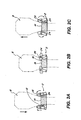
- Figure 2A is a schematic drawing showing a guitar neck being placed in the locking device of the first embodiment
- Figure 2B discloses the locking device in a storage mode
- Figure 2C discloses a musical instrument being removed and releasing the counterweights to open the locking members
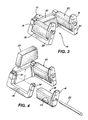
- Figure 3 is a perspective view of the locking device of the first embodiment
- Figure 4 is an exploded view of the locking device of the present invention.
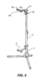
- Figure 5 is a perspective view of a second embodiment of the present invention.
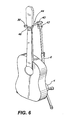
- Figure 6 is a schematic view of the second embodiment storing a musical instrument
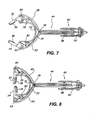
- Figure 7 is a cross-sectional view of the locking device of the second embodiment in an open position
- Figure 8 is a cross-sectional view of a locking device of the second embodiment in a closed position
- Figure 9 is a partial exploded view of the locking device of the second embodiment.
- the locking device alone or in combination with the support stand of the present invention has been illustrated for a musical instrument such as a guitar.
- a musical instrument such as a guitar.
- other musical instruments having a neck or similar taper in particular a stringed instrument such as bass guitars, ukuleles, banjos, violins, violas, cellos, as well as other handheld instruments such as brass and woodwinds which can be hung, fastened or stored in a similar manner as a guitar, can utilize the advantages of the present invention.
- a musical instrument such as a guitar
- musical support stand 4 having an elevated and adjustable pole 6.
- these instruments can have a tripod base as shown.
- a locking device 2 of the first embodiment is shown for locking the neck portion of the musical instrument so that it is suspended in a stored storage mode.
- a cantilevered arm 7 (see Figure 5 ) extending horizontally outward from the pole 6 can distance the body of the guitar away from the pole 6.
- the neck portion of the musical instrument is being inserted into the locking device 2 and contacts pivotable support units 12 having locking members 16 in an open position.
- the musician's hand has placed the musical instrument 8 within the locking device 2 and releases the support of the musical instrument so that the support units 12 are contacted and bear the weight of the musical instrument and rotates with that portion of the musical instrument 8 in contact.
- the musician can pull the instrument 8 downward to contact and activate the locking device rather than rely on a gravitational pull on the instrument 8.
- Counterweights 24 which extend off of a central support rod or shaft 26 are rotated outward as shown in Figure 2B and the integral locking members 16 or crank portions close the entrance opening 14 in a locked mode of storage.
- the base member 10 is configured for mounting on the elevated pole 6 of the support stand 4.
- the support unit includes a pair of U-shaped arms 28 and 30, as seen from a side view.
- the U-shaped arms are inclined outward in a trapezoidal configuration from the front or entrance view 14.
- the U-shaped arms 28 and 30 extend substantially parallel to respectively define the entrance opening 14 and then an extended rivet member or rod 26 can be fastened through the bore openings 32 and 34 to rotatably mount the support members 18, the integral locking member 16, and the counterweight 24.
- the support members 18 can have a resilient surface portion 20 or covering operatively configured to contact the enlarged head of the musical instrument and extending over the counter weight 24 and the interior surface of the lock members.
- the resilient surface portion 20 not only prevents any marring or scratching of the neck, for example of the guitar, but is further positioned to rotate with a downward and upward movement of the guitar during a respective storage and release mode of operation.
- the counterweights 24 can be limited in movement by the roller surface or seat 36 of the respective U-shaped arms. As a result, the counterweights cannot extend within the cavity between the respective U-shaped arms 28 and 30 and will not contact nor mar the musical instruments. Additionally, a defined open position is assured for the respective locking members 16.
- a rear resilient pad 22 of a trapezoidal shape can be mounted on the base member 12 to further protect the musical instrument 8.
- the rear resilient pad can be molded and adhered to a channel on the face of the base member at the rear surface between the U-shaped arms 28 and 30, as shown in Figure 4 and can also limit, at the side edges, the rotational movement of the support members 18 by extending into the space between the support units 18.
- a relatively simple but effective locking device 2 is provided in the first embodiment with components that can be cast or machined to provide a relatively inexpensive and durable locking device. Alternatively it can be made from molded plastic resin compounds. Additionally, the assembly is relatively easy and the locking device can be readily mounted in various forms of musical stands.
- a second embodiment of the present invention is disclosed in the perspective view of Figure 5 of a locking device 38 mounted at the top of a pole 6 on the musical support stand 4.
- a base unit 40 is attached to the top of the pole 6 with a lower pedestal support portion 42.
- a support unit 44 of the locking device 38 has a receptacle portion 46 of a plastic Y shape that can receive the musical instrument when the arms 48 and 50 have their respecting locking members 52 and 54 in an open position.
- FIG. 6 shows the musical instrument 8, such as a guitar, with its neck portion located within the receptacle portion 46 and the respective locking members 52 and 54 in a closed or locking clamped position for storage purposes.
- the supporting unit 44 has been lowered to a horizontal position as further limited by contact with the lower pedestal support 42.
- the body of the musical instrument 8 is positioned away from the pole 6 by the cantilevered arm 7 with appropriate resilient pads as shown in Figure 5 .
- the support unit 44 In comparison with the position of the support unit 44 in Figure 5 , the support unit 44 is biased to an open position by a tension arm spring 64 so that it is inclined slightly in an upward direction relative to the connection to the pole 6 as shown in Figure 9 .
- FIG. 7 and 8 a cross-sectional view of the support unit 44 with the receptacle portion 46 in an open position, is disclosed. Note, the upper covering 82 ( Figure 9 ) is removed in these views.
- Locking members 52 and 54 are extended to an open position and their inward surfaces are provided with flexible cushion pads 56 and 58, respectively.
- the respective locking members 52 and 54 have an L-shape configuration with an open bore at a corner of the L-shape capable of mounting rivets 60 and 62, respectively, to provide a pivot position on the arms 48 and 50.
- the bottom legs of the L-shaped locking members 52 and 54 have open bores for mounting pins 66 and 68 to respectively capture connections at the ends of cables 70 and 72.
- the L-shaped locking members 52 and 54 respectively, have torsion springs 74, one of which is shown in Figure 9 , that are captured by the respective pivots 60 and 62 which bias the respective locking members 52 and 54 to an open position, as shown in Figure 7 .
- respective flexible cables 70 and 72 are guided at the base of the Y by a central pulley 76 by respective pulleys 78 and 80 located in the arms 48 and 50 of the receptacle portion 46.
- the support unit 44 has an upper Y-shaped covering 82 and a lower Y-shaped covering 84.
- the covers are connected together by attachment of the rivets 60 and 62 that also serve to function as pivoting shafts and the mounting of the pivot rivet 86 through the lower covering 84 and the base unit 40, permits the relative movement of the support unit 44.
- the tension arm spring 64 is also held in place by the pivot rivet 86 and biases the support unit 44 to an open position inclined upward from the horizontal support position.
- a stop member 88 extends in the base member across the lower surface of the lower covering 84 and when contacted holds the support unit 44 in a horizontal closed position.
- the ends of the cable 70 and 72 are adjustably mounted onto a fixed block member 90 having a traverse hole for securing the ends of the cable 70 and 72.
- a set screw 94 is utilized to lock the cable block 90 in the desired position at an anchor pivot position offset radially from the pivot rivet 86.
- the support unit 44 is moved upward by the tension arm spring 64 and the cable pull is released so that the respective torsion springs 74 can force open the locking members 52 and 54 whereby the guitar is released from the locking device.
Landscapes
- Physics & Mathematics (AREA)
- Engineering & Computer Science (AREA)
- Acoustics & Sound (AREA)
- Multimedia (AREA)
- Auxiliary Devices For Music (AREA)
- Stringed Musical Instruments (AREA)
Abstract
Description
- The present invention is directed to a locking device for retaining a musical instrument and more particularly to a locking device that can be utilized, for example, with a musical stand or other support structure for operatively suspending a musical instrument during performance and in storage.
- Guitar stands and other supports for musical instruments have been utilized by musicians for a number of years. Typically a guitar stand rests on the floor and supports a guitar from the base and/or the tuning head of the guitar. Alternatively, various structures have been utilized as attachments to walls or to existing stage equipment such as audio speakers, thereby maximizing the available stage space for the performer.
- Tripod musical stands frequently use a fork-like structure that can hold musical instruments such as an acoustical guitar suspended in a state of suspension in an offset manner from the stand. Some stands provide an ability to also support the base of the guitar and in most cases, the supporting stand holds musical instruments such as a guitar for relatively ready access during times when the musician does not want to use the instrument or is unable to handle the musical instrument directly.
- Such occasions frequently occur during a stage performance, during the playing of the instrument, or when the musician is playing another instrument. Preferably the support stand permits a musician to easily place the instrument onto the stand, as well as to be able to quickly retrieve it from the musical stand. Desirably this should be done with a single hand as the musician's other hand may not be free to handle the musical instrument.
- The use of a standard neck fork while facilitating a relatively easy placement and retrieval of the guitar, does not necessarily securely hold it in place while stored on the stand. As can be appreciated, musical instruments can be extremely valuable and can be damaged if they fall from the stand.
- Additionally, a performance stage can be a fairly chaotic environment which is further exacerbated by relatively poor or dim lighting conditions between musical performances when the stage lights may be dimmed or turned off. In this environment, a musician frequently changes instruments and would be either placing and/or retrieving a musical instrument from an instrument stand.
- The
Hsieh (U.S. Patent No. 6,513,768 ) discloses a guitar stand with a locking mechanism to retain the neck of a guitar on a musical instrument stand. -
Hsieh (U.S. Patent No. 6,881,884 ) discloses a guitar stand having arms that can clamp the neck of a guitar that are biased to a closed position. Manually compressing a spring with a handle member can open the arms for receipt of the guitar. -
Hsieh (U.S. Patent No. 7,105,732 ) discloses a movable bracket for receiving a guitar with rotating locking palms on a stationary collar to secure the guitar. -
Wilfer (U.S. Patent No. 7,259,310 ) discloses a wall holder for a musical instrument with relatively movable guide bar brackets. -
Chen (U.S. Patent No. 7,423,209 ) discloses a guitar stand having two arms that are driven along arcuate slots upon receiving the weight of a guitar. The links rotate to secure the guitar neck. - The prior art is still seeking an effecting locking device for retaining a musical instrument on a stand or other support structure and to facilitate an easy release of a musical instrument.
- The present invention permits the storing and retrieving of a musical instrument from a stand that enables a musician to quickly and effectively place the instrument in the instrument stand with one hand and to likewise retrieve the instrument with one hand.
- The present invention can be applied to a number of different musical instruments including but not limited to, guitars of electrical and acoustical versions, banjos, violins, violas, cellos and other handheld instrument categories such as brass and woodwinds, that have a portion of the musical instrument that be grasped and held in storage.
- The present invention provides relatively simple structures utilizing low cost components with reliability and durability.
- In one embodiment of the present invention, gravitational forces can be exerted with counterweights so that a camming surface can rotate when the instrument is inserted and when removed. Locking crank parts can be rotated to an open state when a weight is removed from the camming structure, thereby facilitating the insertion of a portion of a musical instrument to a secure locking position with an easy release from our locking device. The locking device can have a trapezoidal configuration and counterweights can be held in an outer inclined position to avoid potential contact with the instruments. Flexible cushion surfaces can be positioned for further reducing the prospects of marring the surface of the instrument.
- A stand assembly, for example, with a lower tripod base and an elevated pole can permit a desired positioning of a locking device that can be removably secured to the elevated pole.
- A base member on the locking device is configured to support the musical instrument while a support unit is connected to the base member with an entrance opening for a musical instrument. The support unit is positioned to contact and rotate in contact with a musical instrument as the musical instrument is both operatively positioned within the support member for storage and is removed for retrieval.
- A locking member, or preferably a pair of locking members, can be movably mounted on the support unit and are configured to open and close an entrance opening through which a portion of the musical instrument can move, whereby the support unit rotates the locking member from an open to a closed position in a first direction of movement. A second direction of movement of the musical instrument provides an open position for the locking members.
- In a second embodiment of the present invention, a locking device can also be removably attached to a musical stand and includes a base member configured to support the musical instrument.
- A support unit having a receptacle portion, for receiving a portion of a musical instrument, is rotatably connected to the base member so that when a musical instrument is operatively positioned for storage within the receptacle position, the musical instrument's weight can rotate the support unit.
- A locking member or a pair of locking members can be movably mounted on an entrance of the receptacle portion and are configured to open and close the entrance opening. A first rotation of the support unit will move the locking members into a locking position to retain the musical instrument while a second pivotal rotation, in a direction opposite to the first pivotal rotation of the support member, will enable the locking members to be moved to a release position for removal of the musical instrument.
- The support unit can have a planar viewed Y-shape with a locking member biased to an open position at either side of the entrance of the receptacle portion. A cable is operatively connected at one end to each of the locking members to close the locking members when the support unit is rotated to a closed position by the weight of the musical instrument. Pulleys can guide each cable in the receptacle portion with the other end of the cables being adjustably mounted in the base member, whereby rotational movement of the support unit provides a force to the locking members through the respective cables to overcome the bias to provide the closed position.
- A pedestal support can be provided on a musical stand elevated pole, to limit the movement of the support member in a horizontal closed position. When a musical instrument is removed, the support member is raised to an inclined open position.
- The objects and features of the present invention, which are believed to be novel, are set forth with particularity in the appended claims. The present invention, both as to its organization and manner of operation, together with further objects and advantages, may best be understood by reference to the following description, taken in connection with the accompanying drawings.
-
Figure 1 is a perspective view of a first embodiment of the present invention; -
Figure 2A is a schematic drawing showing a guitar neck being placed in the locking device of the first embodiment; -
Figure 2B discloses the locking device in a storage mode; -
Figure 2C discloses a musical instrument being removed and releasing the counterweights to open the locking members; -
Figure 3 is a perspective view of the locking device of the first embodiment; -
Figure 4 is an exploded view of the locking device of the present invention; -
Figure 5 is a perspective view of a second embodiment of the present invention; -
Figure 6 is a schematic view of the second embodiment storing a musical instrument; -
Figure 7 is a cross-sectional view of the locking device of the second embodiment in an open position; -
Figure 8 is a cross-sectional view of a locking device of the second embodiment in a closed position; and -
Figure 9 is a partial exploded view of the locking device of the second embodiment. - Reference will now be made in detail to the preferred embodiments of the invention which set forth the best modes contemplated to carry out the invention, examples of which are illustrated in the accompanying drawings. While the invention will be described in conjunction with the preferred embodiments, it will be understood that they are not intended to limit the invention to these embodiments. On the contrary, the invention is intended to cover alternatives, modifications and equivalents, which may be included within the spirit and scope of the invention as defined by the appended claims. Furthermore, in the following detailed description of the present invention, numerous specific details are set forth in order to provide a thorough understanding of the present invention. However, it will be obvious to one of ordinary skill in the art that the present invention may be practiced without these specific details. In other instances, well known methods, procedures and components have not been described in detail as not to unnecessarily obscure aspects of the present invention.
- The locking device alone or in combination with the support stand of the present invention has been illustrated for a musical instrument such as a guitar. However, other musical instruments having a neck or similar taper, in particular a stringed instrument such as bass guitars, ukuleles, banjos, violins, violas, cellos, as well as other handheld instruments such as brass and woodwinds which can be hung, fastened or stored in a similar manner as a guitar, can utilize the advantages of the present invention.
- Referring to
Figure 1 , andFigures 2A, 2B and 2C , a musical instrument such as a guitar, is disclosed positioned onmusical support stand 4 having an elevated andadjustable pole 6. As can be appreciated, these instruments can have a tripod base as shown. Alocking device 2 of the first embodiment is shown for locking the neck portion of the musical instrument so that it is suspended in a stored storage mode. A cantilevered arm 7 (seeFigure 5 ) extending horizontally outward from thepole 6 can distance the body of the guitar away from thepole 6. - Referring to
Figure 2A , the neck portion of the musical instrument is being inserted into thelocking device 2 and contacts pivotable support units 12 havinglocking members 16 in an open position. While not shown, the musician's hand has placed themusical instrument 8 within thelocking device 2 and releases the support of the musical instrument so that the support units 12 are contacted and bear the weight of the musical instrument and rotates with that portion of themusical instrument 8 in contact. Alternatively, the musician can pull theinstrument 8 downward to contact and activate the locking device rather than rely on a gravitational pull on theinstrument 8.Counterweights 24 which extend off of a central support rod orshaft 26 are rotated outward as shown inFigure 2B and theintegral locking members 16 or crank portions close the entrance opening 14 in a locked mode of storage. - When the musician again grasps the
musical instrument 8 and lifts it upward, its weight is released from thelocking device 2 and thesupport members 18 on the support units 12 and thecounterweights 24 can then rotate under the force of gravity to the lower position to in turn rotate the lockingmember 16 upward and away from blocking the entrance opening 14 to thereby permit a release of themusical instrument 8. - Referring to
Figure 3 , thebase member 10 is configured for mounting on theelevated pole 6 of thesupport stand 4. The support unit includes a pair ofU-shaped arms entrance view 14. TheU-shaped arms entrance opening 14 and then an extended rivet member orrod 26 can be fastened through thebore openings support members 18, theintegral locking member 16, and thecounterweight 24. Thesupport members 18 can have aresilient surface portion 20 or covering operatively configured to contact the enlarged head of the musical instrument and extending over thecounter weight 24 and the interior surface of the lock members. Theresilient surface portion 20 not only prevents any marring or scratching of the neck, for example of the guitar, but is further positioned to rotate with a downward and upward movement of the guitar during a respective storage and release mode of operation. Thecounterweights 24 can be limited in movement by the roller surface orseat 36 of the respective U-shaped arms. As a result, the counterweights cannot extend within the cavity between the respectiveU-shaped arms respective locking members 16. - A rear
resilient pad 22 of a trapezoidal shape can be mounted on the base member 12 to further protect themusical instrument 8. Preferably, the rear resilient pad can be molded and adhered to a channel on the face of the base member at the rear surface between theU-shaped arms Figure 4 and can also limit, at the side edges, the rotational movement of thesupport members 18 by extending into the space between thesupport units 18. - As can be seen in the respective embodiments of
Figures 3 and 4 , a relatively simple buteffective locking device 2 is provided in the first embodiment with components that can be cast or machined to provide a relatively inexpensive and durable locking device. Alternatively it can be made from molded plastic resin compounds. Additionally, the assembly is relatively easy and the locking device can be readily mounted in various forms of musical stands. - A second embodiment of the present invention is disclosed in the perspective view of
Figure 5 of alocking device 38 mounted at the top of apole 6 on themusical support stand 4. - A
base unit 40 is attached to the top of thepole 6 with a lowerpedestal support portion 42. In the embodiment shown inFigure 5 , asupport unit 44 of thelocking device 38 has areceptacle portion 46 of a plastic Y shape that can receive the musical instrument when thearms locking members - The perspective view of
Figure 6 shows themusical instrument 8, such as a guitar, with its neck portion located within thereceptacle portion 46 and therespective locking members unit 44 has been lowered to a horizontal position as further limited by contact with thelower pedestal support 42. The body of themusical instrument 8 is positioned away from thepole 6 by the cantilevered arm 7 with appropriate resilient pads as shown inFigure 5 . - In comparison with the position of the
support unit 44 inFigure 5 , thesupport unit 44 is biased to an open position by a tension arm spring 64 so that it is inclined slightly in an upward direction relative to the connection to thepole 6 as shown inFigure 9 . - Referring also to
Figures 7 and 8 , a cross-sectional view of thesupport unit 44 with thereceptacle portion 46 in an open position, is disclosed. Note, the upper covering 82 (Figure 9 ) is removed in these views. Lockingmembers flexible cushion pads respective locking members rivets arms locking members cables - The L-shaped
locking members Figure 9 , that are captured by therespective pivots respective locking members Figure 7 . As can be seen inFigure 7 , respectiveflexible cables central pulley 76 byrespective pulleys arms receptacle portion 46. - When the
support unit 44 is lowered by the weight of the musical instrument from the open position shown inFigure 7 , the particular offset mounting of therespective cables respective locking members Figure 8 . The pivotal movement of the support unit is displaced from the anchor position of thecables - Referring to
Figure 9 , thesupport unit 44 has an upper Y-shapedcovering 82 and a lower Y-shaped covering 84. When the covers are connected together by attachment of therivets pivot rivet 86 through the lower covering 84 and thebase unit 40, permits the relative movement of thesupport unit 44. The tension arm spring 64 is also held in place by thepivot rivet 86 and biases thesupport unit 44 to an open position inclined upward from the horizontal support position. - A
stop member 88 extends in the base member across the lower surface of the lower covering 84 and when contacted holds thesupport unit 44 in a horizontal closed position. - The ends of the
cable fixed block member 90 having a traverse hole for securing the ends of thecable cable block 90 in the desired position at an anchor pivot position offset radially from thepivot rivet 86. - Since the
pivot rivet 86 is offset and displaced from the anchor point of thecables cable block 90, the rotation of thesupport unit 44 against the bias of the tension arm spring 64, when a musical instrument's weight is deposited inreceptacle portion 46, permits the ends of thecables respective pivots respective locking members respective torsion spring 74 to a locking position. Conversely, when the weight of themusical instrument 8 is removed from thereceptacle portion 46 as the musician lifts, for example, the guitar upward, thesupport unit 44 is moved upward by the tension arm spring 64 and the cable pull is released so that the respective torsion springs 74 can force open the lockingmembers - Those skilled in the art will appreciate that various adaptations and modifications of the just-described preferred embodiment can be configured without departing from the scope and spirit of the invention. Therefore, it is to be understood that, within the scope of the amended claims, the invention may be practiced other than as specifically described herein.
Claims (15)
- A locking device for retaining a musical instrument comprising:a base member configured to support a musical instrument;a support unit connected to the base member and having an entrance opening for the musical instrument and positioned to contact and rotate with the musical instrument as the musical instrument is operatively positioned within the support member for storage; anda locking member movably mounted on the support unit and configured to open and close the entrance opening through which a portion of the musical instrument can move, whereby the support unit rotates the locking member from an open to a closed position in a first direction of movement and in a second direction of movement provides the open position.
- The locking device of Claim 1 further including a counterweight member of sufficient weight and extending from the support unit to rotate the locking member from the closed position to the open position when the musical instrument is removed from contact with the support unit.
- The locking device of Claim 2 wherein the support unit has a resilient surface portion for contacting the musical instrument and is mounted for rotation about a shaft member, the counterweight member extends approximately 180° from the shaft member, relative to the support unit.
- The locking device of Claim 3 wherein the support unit includes a pair of U-shaped arms extending substantially parallel to respectively define the entrance opening.
- The locking device of Claim 4 wherein a support member, a locking member and a counterweight member are operatively mounted on each U-shaped arm.
- The locking device of Claim 1 wherein the base member is configured for mounting on a support stand and forms with the support unit a plane view U-shape with a pair of U-shaped arms viewed traverse to the plane view.
- The locking device of Claim 6 wherein the pair of U-shaped arms are inclined at an angle towards each other and pivotally mount an integral support member, locking member and counterweight member.
- The locking device of Claim 7 wherein each support member has a resilient surface of a curved configuration for physically contacting and rotating with movement of the musical instrument and the locking member is cantilevered from the support member adjacent the entrance opening.
- A locking device for restraining a musical instrument comprising:a base member configured to support a musical instrument;a support unit having a receptacle portion for receiving a portion of the musical instrument, the support unit is connected to the base member and rotatable relative to the base member when the musical instrument is operatively positioned for storage in the receptacle position and the musical instrument's weight rotates the support unit; anda locking member movably mounted on the receptacle portion and configured to open and close an entrance opening of the receptacle portion wherein a first pivotal rotation of the support unit will move the locking member into a locking position to retain the musical instrument and a second pivotal rotation in a direction opposite to the first pivotal rotation will move the locking member to a release position to enable removal of the musical instrument.
- The locking device of Claim 9 wherein the support unit has a planar viewed Y-shape with locking member biased to an open position on the receptacle portion.
- The locking device of Claim 10 wherein a cable is operatively connected at one end to each locking member to close the locking member while the support unit is rotated to the close position.
- The locking device of Claim 11 wherein a pulley guides each cable in the receptacle portion and the other end of each cable is adjustably mounted in the base member whereby rotational movement of the support unit provides a force to the locking member to overcome the bias to provide the closed position.
- The locking device of Claim 12 further including a rotatable block member mounted in the base member for connection to the other end of the cable.
- The locking device of Claim 9 further including a stand assembly and a pedestal support which is operatively mounted on the stand assembly to limit the support member to a horizontal closed position.
- The locking device of Claim 9 further including a spring member in the base member to bias the support member to an upwardly inclined open position from the base member.
Priority Applications (1)
| Application Number | Priority Date | Filing Date | Title |
|---|---|---|---|
| EP10197402A EP2323128B1 (en) | 2008-12-30 | 2009-12-29 | Locking device for retaining a musical instrument |
Applications Claiming Priority (1)
| Application Number | Priority Date | Filing Date | Title |
|---|---|---|---|
| US12/346,581 US7906717B2 (en) | 2008-12-30 | 2008-12-30 | Locking device for retaining a musical instrument |
Publications (2)
| Publication Number | Publication Date |
|---|---|
| EP2204794A2 true EP2204794A2 (en) | 2010-07-07 |
| EP2204794A3 EP2204794A3 (en) | 2010-09-01 |
Family
ID=42028222
Family Applications (2)
| Application Number | Title | Priority Date | Filing Date |
|---|---|---|---|
| EP10197402A Not-in-force EP2323128B1 (en) | 2008-12-30 | 2009-12-29 | Locking device for retaining a musical instrument |
| EP09180885A Withdrawn EP2204794A3 (en) | 2008-12-30 | 2009-12-29 | Locking device for retaining a musical instrument |
Family Applications Before (1)
| Application Number | Title | Priority Date | Filing Date |
|---|---|---|---|
| EP10197402A Not-in-force EP2323128B1 (en) | 2008-12-30 | 2009-12-29 | Locking device for retaining a musical instrument |
Country Status (2)
| Country | Link |
|---|---|
| US (1) | US7906717B2 (en) |
| EP (2) | EP2323128B1 (en) |
Cited By (1)
| Publication number | Priority date | Publication date | Assignee | Title |
|---|---|---|---|---|
| DE102018218230A1 (en) | 2018-10-24 | 2020-04-30 | Guillermo Burgos Teixidó | Holder for hanging a musical instrument |
Families Citing this family (23)
| Publication number | Priority date | Publication date | Assignee | Title |
|---|---|---|---|---|
| US8367919B2 (en) | 2008-01-15 | 2013-02-05 | Swift Distribution, Inc. | Musical support apparatus |
| US8038109B2 (en) * | 2008-08-08 | 2011-10-18 | Dale Frederick Ashford | Amplifier mounted guitar stand |
| US8523201B2 (en) * | 2008-08-26 | 2013-09-03 | Paul Elijah Allen | Retractable device and utility case |
| CN103260474B (en) * | 2010-11-09 | 2016-02-24 | 爱乐威纳克有限责任公司 | Guitar fixing device |
| US9377158B2 (en) * | 2010-12-14 | 2016-06-28 | Randall May International, Inc. | Articulating amplifier stand |
| US9016640B2 (en) | 2011-04-22 | 2015-04-28 | Rks Design, Inc. | Instrument retention assembly |
| US8490942B1 (en) * | 2012-02-13 | 2013-07-23 | Richard Allan Henry | Apparatus and methods for securing a musical instrument |
| ES1077826Y (en) * | 2012-06-15 | 2013-01-18 | Gonzalez Pablo Carrera | Folding bagpipe stand for rest and exposure |
| US20130113420A1 (en) * | 2012-10-02 | 2013-05-09 | John L. Majoris, JR. | Universal Station for Organizing and Charging Multiple Electronic Devices |
| US8925890B2 (en) * | 2012-10-28 | 2015-01-06 | Yuan Terng Liaw | Lock for musical instrument stand |
| US8763961B1 (en) * | 2012-12-21 | 2014-07-01 | Reliance International Corp | Automatic locking guitar holding rack |
| USD689502S1 (en) | 2013-01-18 | 2013-09-10 | Swift Distribution, Inc. | Device support apparatus |
| USD749344S1 (en) * | 2013-01-22 | 2016-02-16 | Swift Distribution, LLC | Support yoke |
| USD748937S1 (en) | 2013-01-22 | 2016-02-09 | Swift Distribution, LLC | Support apparatus |
| US9305529B1 (en) * | 2015-03-06 | 2016-04-05 | Vihren Paounov | Guitar rest |
| CN104810011B (en) * | 2015-03-24 | 2018-06-08 | 宁波江北鑫祥音响电子有限公司 | A kind of music stand |
| CN204635920U (en) * | 2015-05-11 | 2015-09-16 | 深圳市阿诺玛乐器有限公司 | A kind of guitar hooking device |
| USD866231S1 (en) * | 2016-08-25 | 2019-11-12 | Rks Ventures Llc | Guitar stand |
| US10366682B2 (en) * | 2017-03-29 | 2019-07-30 | Ryan Letcher | Positioning apparatus for stringed musical instruments |
| EP3511929B1 (en) * | 2018-01-16 | 2020-11-04 | Wilfer, Hans-Peter | Stand for musical instrument, in particular multiple guitar stand, with support components |
| US10621962B2 (en) * | 2018-08-31 | 2020-04-14 | Walter Castelli | Attachable guitar rest assembly |
| US11869464B2 (en) * | 2020-06-16 | 2024-01-09 | Thomas Harrit | Apparatus for mounting musical instruments |
| US11776517B2 (en) * | 2021-03-25 | 2023-10-03 | Anil K. Gupta | Holder |
Family Cites Families (22)
| Publication number | Priority date | Publication date | Assignee | Title |
|---|---|---|---|---|
| US4205818A (en) | 1979-01-08 | 1980-06-03 | Lawler Frederick D | Musical instrument stand |
| US5372346A (en) | 1992-08-19 | 1994-12-13 | Upchurch; Noel R. | Cushioned swivel hook for stringed instruments |
| US5313866A (en) | 1992-10-30 | 1994-05-24 | Guitar & Light Fabrication | Guitar stand |
| US5664756A (en) | 1996-09-26 | 1997-09-09 | Liao; Yuan-Chi | Article stand |
| US6036159A (en) | 1997-10-24 | 2000-03-14 | Yu; Ming-Ti | Musical instrument stand |
| US6005176A (en) | 1999-03-12 | 1999-12-21 | Yu; Ming-Ti | Light guitar support |
| US6127612A (en) | 1999-09-27 | 2000-10-03 | Yu; Ming-Ti | Guitar stand |
| US6439532B1 (en) | 2000-12-13 | 2002-08-27 | Ming-Ti Yu | Guitar stand |
| US6513768B1 (en) | 2002-01-28 | 2003-02-04 | Wu-Hong Hsieh | Lock for a guitar stand |
| US6772981B1 (en) | 2003-01-02 | 2004-08-10 | Ming-Ti Yu | Musical instrument stand |
| ATE307372T1 (en) | 2003-06-17 | 2005-11-15 | Hans-Peter Wilfer | WALL HOLDER FOR AT LEAST ONE NECK OR SIMILAR TAPERED MUSICAL INSTRUMENT, ESPECIALLY A GUITAR OR BASS GUITAR |
| US7300027B2 (en) | 2003-07-10 | 2007-11-27 | Lawrence Richard Walker | Musical instrument hanger |
| US6881884B2 (en) | 2003-07-18 | 2005-04-19 | Wu-Hong Hsieh | Guitar stand |
| US7002066B2 (en) | 2004-01-20 | 2006-02-21 | Ming-Ti Yu | Musical instrument stand |
| US6982373B1 (en) * | 2004-09-07 | 2006-01-03 | Yu Ming-Ti | Musical instrument stand |
| US7151213B2 (en) * | 2005-03-14 | 2006-12-19 | Wu-Hong Hsieh | Musical instrument stand with a neck lock assembly |
| US7105732B1 (en) | 2005-03-24 | 2006-09-12 | Wu-Hong Hsieh | Musical instrument stand with a self-locking neck lock assembly |
| US7503459B2 (en) | 2005-04-27 | 2009-03-17 | Normark Innovations, Inc. | Device for storing fishing rods and other tools |
| US7351896B2 (en) | 2005-12-05 | 2008-04-01 | Charles Clifford | Clamp for musical instrument |
| US7446249B2 (en) | 2006-08-01 | 2008-11-04 | Joan Driscoll | Support for musical instrument |
| US7423209B2 (en) | 2007-01-16 | 2008-09-09 | Reliance International Corp. | Fixture for a guitar stand |
| US7547835B1 (en) * | 2008-06-27 | 2009-06-16 | Christopher Mayor | Instrument securing device |
-
2008
- 2008-12-30 US US12/346,581 patent/US7906717B2/en not_active Expired - Fee Related
-
2009
- 2009-12-29 EP EP10197402A patent/EP2323128B1/en not_active Not-in-force
- 2009-12-29 EP EP09180885A patent/EP2204794A3/en not_active Withdrawn
Non-Patent Citations (1)
| Title |
|---|
| None |
Cited By (1)
| Publication number | Priority date | Publication date | Assignee | Title |
|---|---|---|---|---|
| DE102018218230A1 (en) | 2018-10-24 | 2020-04-30 | Guillermo Burgos Teixidó | Holder for hanging a musical instrument |
Also Published As
| Publication number | Publication date |
|---|---|
| EP2323128A3 (en) | 2011-12-28 |
| EP2323128B1 (en) | 2012-12-05 |
| US20100163693A1 (en) | 2010-07-01 |
| EP2204794A3 (en) | 2010-09-01 |
| EP2323128A2 (en) | 2011-05-18 |
| US7906717B2 (en) | 2011-03-15 |
Similar Documents
| Publication | Publication Date | Title |
|---|---|---|
| EP2323128B1 (en) | Locking device for retaining a musical instrument | |
| US7342162B2 (en) | Musical instrument stand | |
| US6296213B1 (en) | Multiple musical instrument stand | |
| US5372346A (en) | Cushioned swivel hook for stringed instruments | |
| WO2001094837A1 (en) | Stand for supporting a musical instrument | |
| US8708167B2 (en) | Combination guitar and amplifier stand | |
| US7547834B2 (en) | String replacement assistance apparatus | |
| US20090224113A1 (en) | Portable stand and mount for securing a laptop computer to a support frame | |
| US5154381A (en) | Microphone boom holder | |
| RU2269827C1 (en) | Wall holder for at least one musical instrument having neck or similar narrowing portion, in particular guitar or bass-guitar | |
| US20030173473A1 (en) | Musical instrument supporting stand | |
| GB2368965A (en) | Combined instrument stand and workstation | |
| US5346168A (en) | Guitar hanging fixture | |
| US8440894B2 (en) | Device for supporting a string musical instrument | |
| US6502793B1 (en) | Musical instrument accessory mounting device | |
| JP2002535724A (en) | Multiple instrument holders | |
| US7300027B2 (en) | Musical instrument hanger | |
| US6424723B1 (en) | Microphone holder for mounting a microphone on a drum | |
| US5488890A (en) | String instrument holder | |
| US7772471B2 (en) | Guitar support | |
| US20190228751A1 (en) | In case music instrument stand | |
| US4213369A (en) | Appalachian dulcimer lapboard | |
| US7649131B1 (en) | Wind instrument stand | |
| CN215183004U (en) | Can store formula of pressing from both sides tone tuning ware of plectrum | |
| US10902828B1 (en) | Amplifier equipment mounting system |
Legal Events
| Date | Code | Title | Description |
|---|---|---|---|
| PUAI | Public reference made under article 153(3) epc to a published international application that has entered the european phase |
Free format text: ORIGINAL CODE: 0009012 |
|
| AK | Designated contracting states |
Kind code of ref document: A2 Designated state(s): AT BE BG CH CY CZ DE DK EE ES FI FR GB GR HR HU IE IS IT LI LT LU LV MC MK MT NL NO PL PT RO SE SI SK SM TR |
|
| AX | Request for extension of the european patent |
Extension state: AL BA RS |
|
| PUAL | Search report despatched |
Free format text: ORIGINAL CODE: 0009013 |
|
| AK | Designated contracting states |
Kind code of ref document: A3 Designated state(s): AT BE BG CH CY CZ DE DK EE ES FI FR GB GR HR HU IE IS IT LI LT LU LV MC MK MT NL NO PL PT RO SE SI SK SM TR |
|
| AX | Request for extension of the european patent |
Extension state: AL BA RS |
|
| 17P | Request for examination filed |
Effective date: 20101220 |
|
| GRAP | Despatch of communication of intention to grant a patent |
Free format text: ORIGINAL CODE: EPIDOSNIGR1 |
|
| STAA | Information on the status of an ep patent application or granted ep patent |
Free format text: STATUS: THE APPLICATION IS DEEMED TO BE WITHDRAWN |
|
| 18D | Application deemed to be withdrawn |
Effective date: 20130319 |