EP2204660B1 - Dispositif et procédé de détermination de déchargements partiels sur un composant électrique - Google Patents
Dispositif et procédé de détermination de déchargements partiels sur un composant électrique Download PDFInfo
- Publication number
- EP2204660B1 EP2204660B1 EP08022578.2A EP08022578A EP2204660B1 EP 2204660 B1 EP2204660 B1 EP 2204660B1 EP 08022578 A EP08022578 A EP 08022578A EP 2204660 B1 EP2204660 B1 EP 2204660B1
- Authority
- EP
- European Patent Office
- Prior art keywords
- partial discharge
- filtered
- filters
- electrical component
- signals
- Prior art date
- Legal status (The legal status is an assumption and is not a legal conclusion. Google has not performed a legal analysis and makes no representation as to the accuracy of the status listed.)
- Active
Links
- 238000000034 method Methods 0.000 title claims description 27
- 238000007621 cluster analysis Methods 0.000 claims description 32
- 238000012545 processing Methods 0.000 claims description 29
- 230000008878 coupling Effects 0.000 claims description 12
- 238000010168 coupling process Methods 0.000 claims description 12
- 238000005859 coupling reaction Methods 0.000 claims description 12
- 238000001914 filtration Methods 0.000 claims description 9
- 239000003990 capacitor Substances 0.000 claims description 8
- 238000010292 electrical insulation Methods 0.000 claims description 7
- 238000012360 testing method Methods 0.000 description 24
- 238000005259 measurement Methods 0.000 description 22
- 238000003384 imaging method Methods 0.000 description 18
- 238000001228 spectrum Methods 0.000 description 6
- 230000035508 accumulation Effects 0.000 description 5
- 238000009825 accumulation Methods 0.000 description 5
- 238000009413 insulation Methods 0.000 description 4
- 238000004458 analytical method Methods 0.000 description 3
- 238000010586 diagram Methods 0.000 description 3
- 238000005516 engineering process Methods 0.000 description 3
- 238000011156 evaluation Methods 0.000 description 3
- 230000010355 oscillation Effects 0.000 description 3
- 230000008901 benefit Effects 0.000 description 2
- 230000008033 biological extinction Effects 0.000 description 2
- 230000015556 catabolic process Effects 0.000 description 2
- 239000004020 conductor Substances 0.000 description 2
- 238000000926 separation method Methods 0.000 description 2
- 230000003595 spectral effect Effects 0.000 description 2
- 230000005540 biological transmission Effects 0.000 description 1
- 238000004364 calculation method Methods 0.000 description 1
- 238000006243 chemical reaction Methods 0.000 description 1
- 230000001419 dependent effect Effects 0.000 description 1
- 238000001514 detection method Methods 0.000 description 1
- 230000000694 effects Effects 0.000 description 1
- 230000005284 excitation Effects 0.000 description 1
- 230000001939 inductive effect Effects 0.000 description 1
- 238000009434 installation Methods 0.000 description 1
- 230000010354 integration Effects 0.000 description 1
- 230000002452 interceptive effect Effects 0.000 description 1
- 238000011835 investigation Methods 0.000 description 1
- 239000007788 liquid Substances 0.000 description 1
- 238000004519 manufacturing process Methods 0.000 description 1
- 238000013507 mapping Methods 0.000 description 1
- 239000000203 mixture Substances 0.000 description 1
- 238000012544 monitoring process Methods 0.000 description 1
- 230000000737 periodic effect Effects 0.000 description 1
- 238000000819 phase cycle Methods 0.000 description 1
- 230000008569 process Effects 0.000 description 1
- 238000003908 quality control method Methods 0.000 description 1
- 230000008439 repair process Effects 0.000 description 1
- 230000004044 response Effects 0.000 description 1
- 239000007787 solid Substances 0.000 description 1
Images


Classifications
-
- G—PHYSICS
- G01—MEASURING; TESTING
- G01R—MEASURING ELECTRIC VARIABLES; MEASURING MAGNETIC VARIABLES
- G01R31/00—Arrangements for testing electric properties; Arrangements for locating electric faults; Arrangements for electrical testing characterised by what is being tested not provided for elsewhere
- G01R31/12—Testing dielectric strength or breakdown voltage ; Testing or monitoring effectiveness or level of insulation, e.g. of a cable or of an apparatus, for example using partial discharge measurements; Electrostatic testing
- G01R31/1227—Testing dielectric strength or breakdown voltage ; Testing or monitoring effectiveness or level of insulation, e.g. of a cable or of an apparatus, for example using partial discharge measurements; Electrostatic testing of components, parts or materials
- G01R31/1263—Testing dielectric strength or breakdown voltage ; Testing or monitoring effectiveness or level of insulation, e.g. of a cable or of an apparatus, for example using partial discharge measurements; Electrostatic testing of components, parts or materials of solid or fluid materials, e.g. insulation films, bulk material; of semiconductors or LV electronic components or parts; of cable, line or wire insulation
- G01R31/1272—Testing dielectric strength or breakdown voltage ; Testing or monitoring effectiveness or level of insulation, e.g. of a cable or of an apparatus, for example using partial discharge measurements; Electrostatic testing of components, parts or materials of solid or fluid materials, e.g. insulation films, bulk material; of semiconductors or LV electronic components or parts; of cable, line or wire insulation of cable, line or wire insulation, e.g. using partial discharge measurements
Definitions
- the present invention relates to a method and an apparatus for determining partial discharges on an electrical component, which in particular when carrying out partial discharge measurements of electrical components, such as e.g. High voltage cables, rotating machinery, transformers or the like can be used.
- electrical components such as e.g. High voltage cables, rotating machinery, transformers or the like can be used.
- Partial discharge measurement is a globally recognized quality control procedure both in the laboratory and in the field. Partial discharges (TE) are defined according to IEC 60270 as local dielectric breakdowns in a small part of a solid or liquid electrical insulation system under high voltage stress. Partial discharges often indicate insulation faults on high-voltage components. Reliable detection and monitoring of partial discharges protects against costly failures and repairs and is therefore crucial.
- the TE measurement is one of the main criteria in the assessment of the quality of a cable or a cable set and their installation on site.
- the US 6,377,427 B1 relates to an arc fault protection arrangement in an electrical outlet.
- the arrangement comprises a sensor, a broadband noise circuit and a controller.
- the sensor detects a current and forms a corresponding sensor signal.
- the broadband noise circuit determines the presence of broadband noise in the sensor signal and produces a corresponding output signal.
- the wideband noise circuit may comprise one or more bandpass filter circuits.
- the controller processes the sensor signal and the output signal to determine if there is an arc fault.
- the US 4,063,168 relates to a method for locating the source of coronary discharge. It has been found that unique discharge signature waveforms are associated with the coronary discharges of the components of energy separation filters of repeaters and equalizers. These signature waveforms can be measured and identified by inducing coronary discharges into the high voltage components. A discharge signal generated in response to a corona discharge via a high voltage component has the same shape as one of the signature waveforms.
- coronary discharge from a test repeater or equalizer can be located by comparing its discharge signal with the catalog of signature waveforms. The relationship between the spectral energies of the discharge signal at two predetermined frequencies may be compared with the relationship between the spectral energies of the signature waveforms at the same frequencies. From such a comparison, the most similar signature waveform can be determined and thus the source of the coronary discharge identified.
- the device comprises at least a first and a second sensor and an evaluation device.
- Each of the sensors generates sensor signals for the evaluation device as a function of current pulses through the connection conductors and the direction thereof.
- the evaluation device As a function of the received sensor signals, the evaluation device generates an indication signal which indicates a partial discharge in the test object.
- Fig. 1a shows the course of such a voltage pulse in the time domain and Fig. 1b the frequency spectrum of the voltage pulse of Fig. 1a ,
- the in Fig. 1 shown voltage pulse is a nearly ideal voltage pulse from a Sectionentladkalalibriervorraum.
- a cable or a similar DUT such as an electrical Machine or a transformer
- the voltage signal is subjected to low-pass filtering due to the electrical properties of the specimen before it can be measured.
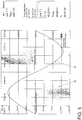
- Fig. 2a shows a low-pass filtered voltage pulse signal
- Fig. 2b the corresponding frequency spectrum.
- real DUTs such as high voltage cables or other electrical machines, cause very complex filtering of the partial discharge signal.
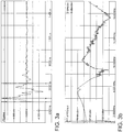
- An example of a real partial discharge signal from a real DUT is in Fig. 3a represented and Fig. 3b shows the corresponding frequency spectrum of the partial discharge signal.
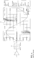
- the partial discharges in the device under test can be converted into a corresponding voltage signal, for example by means of a coupling capacitor and a measuring impedance.
- this voltage signal as in Fig. 4 shown amplified by means of an amplifier 1 and filtered by means of a bandpass filter 2.
- the filter usually has a variable upper and lower limit frequency.
- the filtering is usually set to a low noise frequency band in which the broadband partial discharge pulse clearly stands out from the background noise.
- the filter may, for example, be a bandpass filter with a passband of 50 to 350 kHz.
- the low-pass characteristic of the filter ensures integration of the pulse progression, so that a charge-proportional signal 3 results at the filter output.
- the charge-proportional signal 3 is supplied to a processing unit 4, which collects the charge-proportional signals, which result in a predetermined period of time due to multiple partial discharges, and for example in the in Fig. 4 illustrated manner over the voltage applied to the device under test.
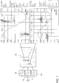
- Fig. 5 shows this representation in detail.
- a complete phase cycle of the voltage applied to the device under test is shown as graph 5 over time.
- the AC voltage applied to the device under test has a frequency of approximately 60 Hz, so that a complete cycle is approximately 16.67 ms.
- the specimen is applied for a predetermined time, in the present example for 47.39 s, with the test voltage indicated by the graph 5.
- a large number of partial discharges occur, each of which is referred to as a point 6 in the in Fig. 5 plotted diagram are plotted.
- a partial discharge is entered with respect to its phase position to the test voltage 5 and their charge size in the diagram. If there is a larger accumulation of points 6 at one point in the diagram, this accumulation can be characterized, for example, by using a different color for the points 6 as a function of the frequency.
- the processing unit 4 determines a total charge of the partial discharges over the predetermined period, which indicates the quality of the test object, for example a high-voltage cable of a predetermined length.
- Another problem with the partial discharge measurement is the separation of several superimposed partial discharge sources from each other.
- a superimposed signal or pulse mixture results at the output of the filter 2, which does not permit a precise statement about the nature and intensity of individual partial discharge sources in the examined test object.
- the statement quality of the partial discharge measurement result can be reduced.
- Another special problem in the partial discharge measurement, especially on cables, is the so-called negative superposition. This results in a superposition of an original partial discharge pulse with a partial discharge pulse reflected at the cable end.
- partial discharge measuring devices are usually tested by double-pulse calibrators. Two successive pulses of defined charge with variable and defined distance are entered into the measuring system, whereby the display value may deviate only by less than 10% from the charge value of the pulse downwards.
- the present invention is therefore based on the object to provide an apparatus and a method for determining partial discharges on an electrical component, whereby the aforementioned problems can be eliminated.
- the invention is based on the object, an apparatus and a method for determining partial discharges on an electrical component, such. Transformers, rotating machinery or cables, which allows a cost-effective and reliable partial discharge measurement.
- the electrical component may be, for example, a high voltage cable, a transformer, an electric generator, an electric drive machine or the like.
- the electrical component may be an electrical component which is suitable for operation with a medium voltage or a high voltage, ie a voltage of a few kV.
- an electrical signal is detected which comprises partial discharge pulses due to dielectric breakdowns in the electrical insulation system of the electrical component.
- the electrical signal can be detected, for example, as described above in the introduction, with the aid of a coupling capacitor and a measuring impedance.
- the detected electrical signal is then fed to multiple filters having different filter characteristics.
- Each of the plurality of filters generates a filtered partial discharge signal from the electrical signal.
- the number of filters is at least two. Thus, at least two filtered partial discharge signals are generated.
- the partial discharges on the electrical component are then determined by combining the plurality of filtered partial discharge signals.
- an n-tuple is formed per partial discharge pulse, wherein values of the n-tuple correspond to the n multiple filtered partial discharge signals of the partial discharge pulse.
- Several n-tuples of several partial discharge pulses are then further processed by means of a cluster analysis. If, for example, n filtered partial discharge signals are generated for each partial discharge pulse with the aid of n filters and entered into a corresponding n-tuple, then this n-tuple can be registered in an n-dimensional imaging space. If several n-tuples of several partial discharge pulses are registered in the n-dimensional imaging space, clusters can be detected at specific locations in the imaging space with the aid of a cluster analysis.
- a partial discharge source which causes a partial discharge in the electrical components can then be identified, for example.
- a combination of different cluster analysis clusters can also be used to identify such a partial discharge source.
- One or more clusters thus constitute a type of signature of a partial discharge phenomenon which is effected as one or more partial discharges from a partial discharge source.
- this partial discharge signature can be identified in a simple manner in the imaging space of the cluster analysis. This makes it easy to identify partial discharge sources, i. Causes of partial discharges in the electrical component, possible.
- interference sources which feed interference signals into the electrical signal can be identified on the basis of a cluster or several clusters of the cluster analysis.
- Such sources of interference can be, for example, electromagnetic high-frequency signals which penetrate into the electrical component and generate interference signals there which generate signal impulses similar to the partial discharges via the electrical signal. These signal pulses also pass through the n filters and are rendered as n-tuples in the imaging space of the cluster analysis as previously described.
- the signature of the interference source ie based on the location of one or more clusters of the cluster analysis, such a noise signal and thus such a source of interference can be identified.
- For determining the partial discharges at the electrical component only those filtered partial discharge signals are used which were not generated by the interference source. As a result, the partial discharges to the electrical component can be determined considerably more accurate, since interference from sources of interference with Cluster analysis help can be easily identified and excluded from the determination of partial discharges.
- an amount is determined for each of the n filtered partial discharge signals and the amounts of the n filtered partial discharge signals are added in a weighted manner.
- determining the magnitude of a filtered partial discharge signal may include squaring the filtered partial discharge signal.
- three filtered partial discharge signals may be generated by filtering the electrical signal with three filters having three different filter characteristics.
- a first of the three filters may, for example, be a bandpass filter with a passband of about 82 to 243 kHz
- a second of the three filters may be a bandpass filter with a passband of about 227 to 387 kHz
- a third of the three filters may have a bandpass filter with a passband of about 377 to 537 kHz.
- weighting factors for weighted adding of the amounts of the three filtered partial discharge signals for example, the following values may be used.
- the partial discharge signal filtered by the first filter may be weighted with the value 1, the partial discharge signal with the value 1,1 filtered by the second filter and the partial discharge signal with the value 1 filtered by the third filter.
- a partial discharge signal results similarly to the filtered partial discharge signal 3 according to the prior art, which by means of the bandpass filter 2, as in connection with Fig. 4 described, is generated.
- Advantage of the partial discharge signal according to the invention, which is formed from the weighted addition, compared to the partial discharge signal 3 of the prior art is that the partial discharge signal according to the invention avoids the problem of the above-described superposition, in particular the negative superposition, since the partial discharge signal according to the invention from a combination of several bandpass filtered partial discharge signals, thereby bypassing the shortcomings of practical filters, such as filter natural oscillations and zeroes, through the different filter characteristics of the multiple bandpass filters.
- an apparatus for determining partial discharges in an electrical insulation system of an electrical component comprises an input port for coupling the device to the electrical component, n filters and a processing unit. Via the input terminal of the device, an electrical signal from the electrical component, such as a high voltage cable, a transformer, an electric generator or an electric drive machine, can be supplied.
- the electrical signal comprises partial discharge pulses which occur due to dielectric impacts in the insulation system of the electrical component.
- the n filters are each coupled on the input side to the input terminal.
- the n filters are each equipped such that on the output side they provide filtered partial discharge signals as a function of the electrical signal. Thus, n filtered partial discharge signals are provided at the n outputs of the n filters.
- the n filters have n different filter characteristics.
- the device comprises at least two filters, ie, n ⁇ 2.
- the processing unit is coupled to the outputs of the n filters and configured to determine the partial discharges by combining the n filtered partial discharge signals. Furthermore, the processing unit forms an n-tuple for each partial discharge pulse, the n values of the n-tuple corresponding to the n filtered partial discharge signals of the partial discharge pulse.
- a filtered partial discharge signal may comprise, for example, a charge-proportional signal of the partial discharge pulse as a function of the filter characteristic of the corresponding filter.
- the processing unit comprises a cluster analysis unit which determines clusters or accumulations of partial discharge pulses by means of a cluster analysis of a plurality of n-tuples of a plurality of partial discharge pulses.
- the cluster analysis unit can enter an n-tuple into an n-dimensional imaging space, where an n-tuple designates a point in the n-dimensional imaging space, wherein each of the n values of the n-tuple is assigned to one dimension of the n-dimensional space , If a sufficient number of partial discharge pulses are detected and their corresponding n-tuples registered in the n-dimensional imaging space, so can accumulations of partial discharge pulses in areas of the imaging space can be determined by cluster analysis.
- the processing unit may identify causes, so-called partial discharge sources, which cause a partial discharge phenomenon on the electrical component.
- Partial discharge sources can be identified, for example, by the position of a cluster or by the position of several clusters. As a result, not only is a determination of the partial discharges on the electrical component possible, but also a determination of partial discharge sources, which cause the partial discharges, is possible.
- Clustering clusters allow the processing unit to continue to identify sources of interference.
- a source of interference causes spurious signals to be present in the electrical signal which, similar to the partial discharges behind the n filters, produce signals which are similar to the filtered partial discharge signals.
- Noise from typical sources of interference, such as Radio frequency transmitters can then be identified by means of cluster analysis, since these interference signals in the imaging space as well as the partial discharges form characteristic clusters or clusters.
- interference signals can be identified in a simple manner and these can be disregarded in determining the partial discharges from the processing unit.
- the processing unit is configured such that it determines amounts of the n filtered partial discharge signals and multiplies these n amounts each time with its own weighting factor. The determination of an amount can be determined, for example, by squaring the corresponding filtered partial discharge signal. Furthermore, the processing unit is configured to sum the weighted amounts to determine therefrom the amount of a partial discharge of the electrical component. As described above in connection with the method according to the invention, by using the plurality of filters and merging the filtered partial discharge signals, an amount of a partial discharge can be determined which is not falsified by superposition, in particular negative superposition on high-voltage cables.
- a first of the three filters may be a bandpass filter with a passband of about 82-243 kHz
- a second of the three filters may be a bandpass filter with a passband of about 227-387 kHz
- a third of the three filters may have a bandpass filter a passband of about 377-537 kHz.
- the weighting factors are set as follows, for example: a first weighting factor for weighted adding the partial discharge signal filtered by the first filter has the value 1, a second weighting factor for weighting the partial filter filtered partial discharge signal has the value 1.1, and a third weighting factor for weighting the The partial discharge signal filtered by the third filter has the value 1.
- the filter structure thus defined has a passband of approximately 82-537 kHz and is at the same time robust against a superposition, in particular a negative superposition, which is caused by filter natural oscillations and / or zeros in the filter , As a result, an extinction or attenuation of two rapidly successive partial discharge signal pulses, as may originate, for example, from an original pulse and a pulse reflected at the cable end, can be reliably avoided.
- Fig. 6 shows an electrical component 10 and a partial discharge measuring device 11 for determining partial discharges on the electrical component 10.
- the electrical component 10 may be for example an electrical machine, such as an electric generator or an electric motor, a transformer or a cable. Partial discharge measurements are usually carried out on electrical components which are operated for operation in the medium voltage or high voltage range, ie with voltages of a few kV.
- the electrical component 10 is connected via a connection 12 to a corresponding medium-voltage or high-voltage source V, usually an AC voltage source.
- a housing or a shield of the electrical component 10 is connected to ground 13.
- the electrical component 10 is also referred to below as the test object 10.
- Fig. 3b shows the spectrum of this signal.
- the integral over this signal is proportional to the charge of the partial discharge in the device under test 10.
- This partial discharge pulse measured at the measuring point 16 is amplified by means of an amplifier 17 of the partial discharge measuring device 11 and fed to three bandpass filters 18-20 of the partial discharge measuring device 11.
- Each of the bandpass filters 18-20 has a different passband, for example, the bandpass filter 18 has one The passband is 82.5-242.5 kHz, the bandpass filter 19 has a passband of 227-387 kHz, and the bandpass filter 20 has a passband of 377-537 kHz.
- the outputs of the band-pass filters 18 - 20, which are called hereinafter filtered partial discharge signals, are supplied to a processing unit 21 of the partial discharge measuring device 11.
- interfering signals are filtered out at the measuring point 16.
- These can be, for example, conducted interference sources which generate signals in the range from 0 to a few kHz.
- these can be sources of interference that generate high-frequency signals in the range of a few MHz.
- the low-pass filtering of the low-pass filters 18-20 causes the partial discharge pulses to be integrated so that a value is available at the output of each filter which is proportional to the charge of the partial discharge.
- a partial discharge measurement is performed over a predetermined period of time. During this predetermined period of time, a large number of partial discharges, for example several thousand partial discharges, occur. Since the excitation of the device under test 10 is periodic, for example by means of an AC voltage of 50 or 60 Hz, partial discharges due to a source of interference in the device under test, such as an insulation bubble or the like, during the measurement period of for example a few tens of seconds repeatedly occur with similar intensity , Fig. 5 shows a representation of the partial discharge events taking into account the phase position of the partial discharges to the applied AC voltage and the size of the partial discharge.
- Each partial discharge pulse has a very broad frequency spectrum, as related to Fig. 1-3 already described.
- each partial discharge pulse also has pulse components in the frequency spectra, which are defined as the transmission frequencies of the filters 18-20.
- each partial discharge pulse at each of the filters 18-20 causes a signal output.
- different filtered partial discharge signals result at the outputs of the filters 18-20.
- a partial discharge source cause a large signal at the output of the filter 18 and a small signal at the outputs of the filters 19 and 20.
- a further partial discharge source however, at the output of the filter 19 cause a large signal, whereas at the outputs of the filter 18th and 20 only a small signal is effected.
- each partial discharge source has its own signature, a so-called frequency signature, which is described by the three values of the filters 18-20.
- This frequency signature can, as related to Fig. 7 will be used to perform a cluster analysis of the filtered partial discharge signals and thus to identify partial discharge sources.
- Fig. 7 schematically shows the method of this cluster analysis.
- the measuring signal is amplified by means of the amplifier 17 and passed over the three filters 18-20.
- a cluster analysis is then carried out, which in a three-dimensional imaging space 22 enters the partial discharge pulses on the basis of the three filtered partial discharge signals of the filters 18-20.
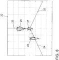
- Fig. 8 shows an enlarged view of the three-dimensional imaging space 22 with the three spatial axes 23-25.
- Each partial discharge signal is input to the imaging space 22 in accordance with the filtered partial discharge signal values of the filters 18-20.
- the filtered partial discharge signal value of the filter 18 is plotted on the spatial axis 23, the filtered partial discharge signal value of the filter 19 is plotted on the spatial axis 24 and the filtered partial discharge signal value of the filter 20 is plotted on the spatial axis 25.
- partial discharge clusters result in certain areas of the imaging space 22 Fig. 8 are three such clusters, so-called clusters shown. Partial discharges, shown in the region of the cluster 26, have caused a large filtered partial discharge signal at the output of the filter 18 and relatively small partial discharge signals at the outputs of the filters 19 and 20.
- partial discharges in the region of the cluster 28 have caused large filtered partial discharge signals at the output of the filter 19 and small partial discharge signals at the outputs of the filters 18 and 20. Due to these frequency signatures, which can be assigned to the individual clusters 26-28, partial discharge sources can thus be identified in a simple manner by the processing unit 21. In addition, expenses that are comparable to the output of the Fig. 5 For each of the clusters 26-28 are provided separately from the processing unit 21. As a result, a more detailed analysis of the different sources of interference and their influence on the overall quality of the test object 10 is possible.
- interference signals which are detected at the measuring point 16
- noise may for example be present in the passband of the filters 18-20, which thus can not be eliminated by the filters 18-20.
- These disturbances for example, line-bound disturbances from the supply voltage V or electromagnetic interference from radio transmitters or electrical machines or electrical lines in the surroundings of the test object 10, also lead to clusters or clusters in the imaging space 22 since these disturbances typically also each have a characteristic frequency signature.
- the processing unit 21 can identify such accumulations as disturbances and disregard them in the calculation of a total partial discharge of the test object 10 by disregarding the corresponding supposedly filtered partial discharge signals.
- the measuring accuracy with respect to the partial discharge measuring device according to the prior art Fig. 4
- Fig. 9 shown filter structure and further processing compared to the filter 2 according to the prior art ( Fig. 4 ), lies in the robustness of the invention Filter structure ( Fig. 9 ) against superposition or overlay effects of multiple partial discharge sources.
- a real filter like the one in Fig. 4 shown bandpass filter 2, when it is subjected to certain pulse patterns, tend to oscillate and / or have zeros. This can lead to mutual cancellation or attenuation or superimposition of two or more partial discharge pulses. This problem occurs especially in partial discharge measurements on cables.
- an extinction a so-called negative superposition, can come about by superposition of an original partial discharge pulse with a partial discharge pulse reflected at the end of the cable.
- cluster analysis which in connection with Fig. 7 and 8th and the weighted summation associated with Fig. 9 2, based on the parallel filtering of the partial discharge pulse with the aid of the filters 18-20, the two methods can be combined in a simple manner in a processing unit 21 in order to carry out a partial discharge measurement which is both robust against sources of interference and robust with respect to the above described negative superposition.
- cluster analysis can provide improved identification of partial discharge noise sources.
Claims (16)
- Procédé servant à déterminer des déchargements partiels au niveau d'un composant électrique, comprenant les étapes consistant à :- détecter un signal électrique, qui comprend des impulsions de déchargement partiel du fait des déchargements partiels (6) au niveau du composant électrique (10),- générer n signaux de déchargement partiel filtrés en filtrant le signal électrique avec n filtres (18 - 20) avec n caractéristiques de filtre différentes, dans lequel respectivement un des signaux de déchargement partiel filtrés est associé respectivement à l'un des n filtres (18 - 20), dans lequel n est supérieur ou égal à 2,- obtenir un n-uplet respectif par impulsion de déchargement partiel, dans lequel des valeurs du n-uplet correspondent aux n signaux de déchargement partiel filtrés de l'impulsion de déchargement partiel, et- déterminer des signatures de déchargement partiel des déchargements partiels (6) en combinant les n signaux de déchargement partiel filtrés, dans lequel la combinaison comprend une analyse par grappes des n-uplets.
- Procédé selon la revendication 1, caractérisé en ce qu'une source de déchargement partiel, qui entraîne un déchargement partiel (6) dans le composant électrique (10), est identifiée à l'aide d'au moins une grappe (26 - 28) de l'analyse par grappes.
- Procédé selon l'une quelconque des revendications 1 ou 2, caractérisé en ce
que le signal électrique comprend en outre des signaux parasites, qui sont générés par une source parasite à l'intérieur ou à l'extérieur du composant électrique (10) et qui sont fournis en tant que signaux de déchargement partiel filtrés par les n filtres (18 - 20),
que la source parasite est identifiée à l'aide d'au moins une grappe (26 - 28) de l'analyse par grappes, et
qu'afin de déterminer les déchargements partiels (6) du composant électrique (10), des signaux de déchargement partiel filtrés sont seulement utilisés, lesquels n'ont pas été générés par la source parasite. - Procédé selon l'une quelconque des revendications 1 - 3, caractérisé en ce que la combinaison comprend une détermination d'un montant pour chacun des n signaux de déchargement partiel filtrés et un ajout pondéré des montants des n signaux de déchargement partiel filtrés.
- Procédé selon la revendication 4, caractérisé en ce
qu'un premier filtre des n filtres est un filtre passe-bande (18) avec une bande passante d'environ 82 - 243 kHz, un deuxième des n filtres est un filtre passe-bande (19) avec une bande passante d'environ 227 - 387 kHz, et un troisième des n filtres est un filtre passe-bande (20) avec une bande passante d'environ 377 - 537 kHz, et
qu'un premier facteur de pondération (W1) servant à ajouter de manière pondérée le signal de déchargement partiel filtré par le premier filtre (18) a la valeur 1, un deuxième facteur de pondération (W2) servant à ajouter de manière pondérée le signal de déchargement partiel filtré par le deuxième filtre (19) a la valeur 1,1, et un troisième facteur de pondération (W3) servant à ajouter de manière pondérée le signal de déchargement partiel filtré par le troisième filtre (20) a la valeur 1. - Procédé selon l'une quelconque des revendications 1 - 5, caractérisé en ce que s'applique n = 3.
- Procédé selon l'une quelconque des revendications 1 - 6, caractérisé en ce que le composant électrique (10) comprend un câble à haute tension, un transformateur, un générateur électrique ou une machine d'entraînement électrique.
- Dispositif servant à déterminer des déchargements partiels au niveau d'un composant électrique, comprenant- une borne d'entrée (16) servant à coupler le dispositif (11) au composant électrique (10), dans lequel un signal électrique provenant du composant électrique (10) peut être amené au dispositif (11) par l'intermédiaire de la borne d'entrée, lequel comprend des impulsions de déchargement partiel du fait des déchargements partiels (6) au niveau du composant électrique (10),- n filtres (18 - 20), qui sont couplés du côté de l'entrée à la borne d'entrée (16) et qui sont configurés pour fournir du côté de la sortie n signaux de déchargement partiel filtrés en fonction du signal électrique, dans lequel les n filtres (18 - 20) présentent n caractéristiques de filtre, dans lequel n est supérieur ou égal à 2, et- une unité de traitement (21), qui est couplée aux sorties des n filtres (18 - 20),dans lequel l'unité de traitement (21) est configurée
pour former par impulsion de déchargement partiel un n-uplet, dans lequel des valeurs du n-uplet correspondent aux n signaux de déchargement partiel filtrés de l'impulsion de déchargement partiel, et
pour déterminer des signatures de déchargement partiel des déchargements partiels (6) en combinant les n signaux de déchargement partiel filtrés, dans lequel l'unité de traitement (21) servant à combiner les n signaux de déchargement partiel filtrés comprend une unité d'analyse par grappes, qui est configurée pour déterminer des grappes (26 - 28) d'impulsions de déchargement partiel au moyen d'une analyse par grappes de plusieurs n-uplets de plusieurs impulsions de déchargement partiel. - Dispositif selon la revendication 8, caractérisé en ce que l'unité de traitement (21) est configurée pour identifier à l'aide des grappes (26 - 28) de l'unité d'analyse par grappes une source de déchargement partiel, qui entraîne un déchargement partiel (6) au niveau du composant électrique (10), à l'aide d'au moins une grappe (26 - 28).
- Dispositif selon l'une quelconque des revendications 8 ou 9, caractérisé en ce
que le signal électrique comprend en outre des signaux parasites, qui sont générés par une source parasite à l'intérieur ou à l'extérieur du composant électrique (10) et qui sont fournis en tant que signaux de déchargement partiel filtrés par les n filtres (18 - 20),
que l'unité de traitement (21) est configurée pour identifier à l'aide des grappes (26 - 28) de l'unité d'analyse par grappes la source parasite à l'aide d'au moins une grappe (26 - 28), et
que l'unité de traitement (21) est configurée pour déterminer les déchargements partiels (6) du composant électrique (10) en ce qu'elle n'utilise que des signaux de déchargement partiel filtrés, qui n'ont pas été générés par la source parasite. - Dispositif selon l'une quelconque des revendications 8 - 10, caractérisé en ce que l'unité de traitement (21) est configurée
pour déterminer n montants des n signaux de déchargement partiel filtrés,
pour multiplier les n montants respectivement par un facteur de pondération (W1 - W3) propre, et
pour additionner les montants pondérés afin de déterminer sur cette base le montant d'un déchargement partiel (6) du composant électrique. - Dispositif selon la revendication 11, caractérisé en ce
qu'un premier des n filtres est un filtre passe-bande (18) avec une bande passante d'environ 82 - 243 kHz, un deuxième filtre des n filtres est un filtre passe-bande (19) avec une bande passante d'environ 227 - 387 kHz et un troisième des n filtres est un filtre passe-bande (20) avec une bande passante d'environ 377 - 537 kHz, et
qu'un premier facteur de pondération (W1) servant à ajouter de manière pondérée le signal de déchargement partiel filtré par le premier filtre (18) a la valeur 1, un deuxième facteur de pondération (W2) servant à ajouter de manière pondérée le signal de déchargement partiel filtré par le deuxième filtre (19) a la valeur 1,1 et un troisième facteur de pondération (W3) servant à ajouter de manière pondérée le signal de déchargement partiel filtré par le troisième filtre (20) a la valeur 1. - Dispositif selon l'une quelconque des revendications 8 - 12, caractérisé en ce que s'applique n = 3.
- Dispositif selon l'une quelconque des revendications 8 - 13, caractérisé en ce que le dispositif (10) comprend en outre un condensateur de couplage (14) et une impédance de mesure (15),
dans lequel le condensateur de couplage (14) couple la borne d'entrée (16) à une alimentation en tension (V) du composant électrique (10), et
dans lequel l'impédance de mesure (15) couple la borne d'entrée (16) à une masse (13) du composant électrique (10). - Dispositif selon l'une quelconque des revendications 8 - 14, caractérisé en ce que chacun des n filtres (18 - 20) est configuré de telle manière que le signal de déchargement partiel filtré est proportionnel par rapport à une charge du déchargement partiel (6) correspondant.
- Dispositif selon l'une quelconque des revendications 8 - 15, caractérisé en ce que le composant électrique (10) comprend un câble à haute tension, un transformateur, un générateur électrique ou une machine d'entraînement électrique.
Priority Applications (3)
| Application Number | Priority Date | Filing Date | Title |
|---|---|---|---|
| EP08022578.2A EP2204660B1 (fr) | 2008-12-30 | 2008-12-30 | Dispositif et procédé de détermination de déchargements partiels sur un composant électrique |
| PCT/EP2009/009262 WO2010076002A1 (fr) | 2008-12-30 | 2009-12-23 | Dispositif et procédé permettant de déterminer des décharges partielles sur un composant électrique |
| US13/142,920 US8760171B2 (en) | 2008-12-30 | 2009-12-23 | Device and method for determining partial discharges at an electrical component |
Applications Claiming Priority (1)
| Application Number | Priority Date | Filing Date | Title |
|---|---|---|---|
| EP08022578.2A EP2204660B1 (fr) | 2008-12-30 | 2008-12-30 | Dispositif et procédé de détermination de déchargements partiels sur un composant électrique |
Publications (2)
| Publication Number | Publication Date |
|---|---|
| EP2204660A1 EP2204660A1 (fr) | 2010-07-07 |
| EP2204660B1 true EP2204660B1 (fr) | 2018-06-27 |
Family
ID=40637153
Family Applications (1)
| Application Number | Title | Priority Date | Filing Date |
|---|---|---|---|
| EP08022578.2A Active EP2204660B1 (fr) | 2008-12-30 | 2008-12-30 | Dispositif et procédé de détermination de déchargements partiels sur un composant électrique |
Country Status (3)
| Country | Link |
|---|---|
| US (1) | US8760171B2 (fr) |
| EP (1) | EP2204660B1 (fr) |
| WO (1) | WO2010076002A1 (fr) |
Families Citing this family (12)
| Publication number | Priority date | Publication date | Assignee | Title |
|---|---|---|---|---|
| ES2379831A1 (es) * | 2010-05-26 | 2012-05-04 | Universidad Politécnica de Madrid | PROCEDIMIENTO DE MONITORIZACIÓN CONTINUA Y DIAGNÓSTICO DE FUENTES DE DESCARGAS PARCIALES (DPs) EN CABLES DE ALTA TENSIÓN DURANTE SU CONEXIÓN Y FUNCIONAMIENTO EN LA RED, Y SISTEMA FÍSICO PARA LA PUESTA EN PRÁCTICA DEL PROCEDIMIENTO. |
| AU2010358396B2 (en) * | 2010-07-26 | 2016-05-05 | Prysmian S.P.A. | Apparatus and method for monitoring an electric power transmission system through partial discharges analysis |
| US8797045B2 (en) * | 2011-03-25 | 2014-08-05 | Doble Lemke Gmbh | Device for detecting partial discharge in an insulation system of rotary electric machines |
| JP2015175613A (ja) * | 2014-03-13 | 2015-10-05 | 日立金属株式会社 | 電線の評価方法及び電線の評価装置 |
| EP3133408B1 (fr) * | 2015-08-21 | 2020-06-17 | Power Diagnostix Instruments GmbH | Procédé pour tester des composants électriques |
| CA3007729A1 (fr) | 2017-06-12 | 2018-12-12 | Vibrosystm Inc. | Methode de surveillance de decharges partielles dans une machine electrique a haute tension, et cable de connexion associe |
| WO2020161967A1 (fr) * | 2019-02-04 | 2020-08-13 | 住友電気工業株式会社 | Dispositif de détection de décharge partielle |
| EP3796011A1 (fr) * | 2019-09-18 | 2021-03-24 | Siemens Aktiengesellschaft | Évaluation de signaux d'évacuation de pièces |
| AT523525B1 (de) | 2020-03-31 | 2021-09-15 | Baur Gmbh | Elektrische Schaltungsanordnung |
| CN111737847B (zh) * | 2020-05-07 | 2023-05-23 | 中国工程物理研究院应用电子学研究所 | 一种强电磁脉冲环境构建等效性量化分级评估方法 |
| US20220244320A1 (en) * | 2021-01-29 | 2022-08-04 | Texas Instruments Incorporated | Low cost method-b high voltage isolation screen test |
| CN113884837B (zh) * | 2021-11-03 | 2023-07-28 | 国网河南省电力公司驻马店供电公司 | 一种电缆局部放电在线监测分析系统及分析方法 |
Citations (2)
| Publication number | Priority date | Publication date | Assignee | Title |
|---|---|---|---|---|
| US5933012A (en) * | 1995-09-14 | 1999-08-03 | Abb Research Ltd. | Device for sensing of electric discharges in a test object |
| WO2000020878A1 (fr) * | 1998-10-07 | 2000-04-13 | General Electric Company | Detecteur de contamination d'enroulement du moteur et detection |
Family Cites Families (5)
| Publication number | Priority date | Publication date | Assignee | Title |
|---|---|---|---|---|
| US4063168A (en) | 1975-11-07 | 1977-12-13 | Bell Telephone Laboratories, Incorporated | Method and apparatus for locating the source of corona discharge |
| WO1994001910A1 (fr) | 1992-07-10 | 1994-01-20 | Technisearch Limited | Detecteur de defauts d'impedance elevee |
| US6377427B1 (en) | 1995-03-13 | 2002-04-23 | Square D Company | Arc fault protected electrical receptacle |
| SE9700836L (sv) | 1997-03-10 | 1998-09-07 | Abb Research Ltd | Anordning för avkänning av elektriska urladdningar i ett provobjekt med två elektriska anslutningsledare |
| ITPR20060054A1 (it) | 2006-06-13 | 2007-12-14 | Techimp S R L | Strumento e procedimento di rilevazione di scariche elettriche parziali in un sistema elettrico |
-
2008
- 2008-12-30 EP EP08022578.2A patent/EP2204660B1/fr active Active
-
2009
- 2009-12-23 US US13/142,920 patent/US8760171B2/en active Active
- 2009-12-23 WO PCT/EP2009/009262 patent/WO2010076002A1/fr active Application Filing
Patent Citations (2)
| Publication number | Priority date | Publication date | Assignee | Title |
|---|---|---|---|---|
| US5933012A (en) * | 1995-09-14 | 1999-08-03 | Abb Research Ltd. | Device for sensing of electric discharges in a test object |
| WO2000020878A1 (fr) * | 1998-10-07 | 2000-04-13 | General Electric Company | Detecteur de contamination d'enroulement du moteur et detection |
Non-Patent Citations (2)
| Title |
|---|
| BORGHETTO J ET AL: "Partial Discharge Inference by an Advanced System. Analysis of Online Measurements Performed on Hydrogenerator", IEEE TRANSACTIONS ON ENERGY CONVERSION, IEEE SERVICE CENTER, PISCATAWAY, NJ, US, vol. 19, no. 2, 1 June 2004 (2004-06-01), pages 333 - 339, XP011113368, ISSN: 0885-8969, DOI: 10.1109/TEC.2004.827473 * |
| G.C. STONE: "Partial discharge diagnostics and electrical equipment insulation condition assessment", IEEE TRANSACTIONS ON DIELECTRICS AND ELECTRICAL INSULATION., vol. 12, no. 5, 1 October 2005 (2005-10-01), US, pages 891 - 903, XP055101396, ISSN: 1070-9878, DOI: 10.1109/TDEI.2005.1522184 * |
Also Published As
| Publication number | Publication date |
|---|---|
| EP2204660A1 (fr) | 2010-07-07 |
| US8760171B2 (en) | 2014-06-24 |
| WO2010076002A1 (fr) | 2010-07-08 |
| US20110291666A1 (en) | 2011-12-01 |
Similar Documents
| Publication | Publication Date | Title |
|---|---|---|
| EP2204660B1 (fr) | Dispositif et procédé de détermination de déchargements partiels sur un composant électrique | |
| EP0241764B1 (fr) | Procédé et appareil pour détecter et localiser des dommages dans des installations électriques | |
| DE19507826C2 (de) | Vorrichtung zum Feststellen von Störungen oder Schäden einer elektrischen Einrichtung oder einer rotierenden elektrischen Maschine | |
| DE69637461T2 (de) | Überwachung von teilentladungen in leistungstransformatoren | |
| EP2041591B1 (fr) | Procédé et dispositif pour la détection de courts-circuits interlaminaires | |
| EP1537390B1 (fr) | Procede pour saisir des oscillations de la ligne d'arbres d'une machine electrique | |
| DE102006043120B4 (de) | Breitband-Ultrahochfrequenz-Simulations-Teilentladungsgenerator | |
| EP2623999B1 (fr) | Procédé de localisation d'une faute dans un câble de test et dispositif correspondant | |
| CH700936B1 (de) | Verfahren und System zum Bestimmen einer vor einem Ausfall eines Elektromotorsystems verbleibenden Zeit. | |
| EP3182145A1 (fr) | Procédé et dispositif de recherche étendue de défaut d'isolation dans un système d'alimentation électrique non relié à la terre et procédé de surveillance d'état d'un système d'alimentation électrique | |
| AT511807A4 (de) | Verfahren und vorrichtung zur online-erkennung einer zustandsverschlechterung einer isolierung in einer elektrischen maschine | |
| EP1537428B1 (fr) | Procede et dispositif pour detecter des etincelles aux balais et de l'erosion par etincelles dans des machines electriques | |
| EP0596879B1 (fr) | Procede et dispositif de reconnaissance de defauts dans des systemes convertisseurs | |
| DE102014005698A1 (de) | Verfahren sowie Vorrichtung zur ortsaufgelösten Diagnose | |
| EP2963752B1 (fr) | Dispositif de protection différentielle destiné à la détection de courant de fuite | |
| EP3870983B1 (fr) | Analyse d'état d'un matériel électrique | |
| WO2017121846A1 (fr) | Procédé et dispositif de surveillance d'un court-circuit d'une charge triphasée | |
| EP0662220A1 (fr) | Decouplage d'un signal d'erreur haute frequence d'un champ electromagnetique haute frequence dans une machine electrique de grande dimension. | |
| EP0520193B1 (fr) | Procédé pour messurer des décharges partielles | |
| EP0917979A1 (fr) | Méthode pour surveiller le courant parasit et l'état des véhicules ferroviares | |
| EP2290385A1 (fr) | Système de surveillance pour transformateurs de puissance et procédé de surveillance | |
| DE19932611A1 (de) | Verfahren und Vorrichtung zur Messung von Teilentladungssignalen | |
| DE19519744A1 (de) | Verfahren und Vorrichtung zum Bestimmen von Isolationseigenschaften von Prüfobjekten | |
| CH677287A5 (fr) | ||
| DE102020135173A1 (de) | Diagnosevorrichtung für eine Überwachung einer Kenngröße an einer elektrischen Hochspannungskomponente, Messanordnung und Verfahren zum Auswerten von Messsignalen |
Legal Events
| Date | Code | Title | Description |
|---|---|---|---|
| PUAI | Public reference made under article 153(3) epc to a published international application that has entered the european phase |
Free format text: ORIGINAL CODE: 0009012 |
|
| AK | Designated contracting states |
Kind code of ref document: A1 Designated state(s): AT BE BG CH CY CZ DE DK EE ES FI FR GB GR HR HU IE IS IT LI LT LU LV MC MT NL NO PL PT RO SE SI SK TR |
|
| AX | Request for extension of the european patent |
Extension state: AL BA MK RS |
|
| 17P | Request for examination filed |
Effective date: 20101216 |
|
| 17Q | First examination report despatched |
Effective date: 20110107 |
|
| AKX | Designation fees paid |
Designated state(s): AT BE BG CH CY CZ DE DK EE ES FI FR GB GR HR HU IE IS IT LI LT LU LV MC MT NL NO PL PT RO SE SI SK TR |
|
| GRAP | Despatch of communication of intention to grant a patent |
Free format text: ORIGINAL CODE: EPIDOSNIGR1 |
|
| INTG | Intention to grant announced |
Effective date: 20180302 |
|
| GRAS | Grant fee paid |
Free format text: ORIGINAL CODE: EPIDOSNIGR3 |
|
| GRAA | (expected) grant |
Free format text: ORIGINAL CODE: 0009210 |
|
| AK | Designated contracting states |
Kind code of ref document: B1 Designated state(s): AT BE BG CH CY CZ DE DK EE ES FI FR GB GR HR HU IE IS IT LI LT LU LV MC MT NL NO PL PT RO SE SI SK TR |
|
| REG | Reference to a national code |
Ref country code: GB Ref legal event code: FG4D Free format text: NOT ENGLISH |
|
| REG | Reference to a national code |
Ref country code: CH Ref legal event code: NV Representative=s name: FELBER UND PARTNER AG, CH |
|
| REG | Reference to a national code |
Ref country code: AT Ref legal event code: REF Ref document number: 1012791 Country of ref document: AT Kind code of ref document: T Effective date: 20180715 |
|
| REG | Reference to a national code |
Ref country code: IE Ref legal event code: FG4D Free format text: LANGUAGE OF EP DOCUMENT: GERMAN |
|
| REG | Reference to a national code |
Ref country code: DE Ref legal event code: R096 Ref document number: 502008016148 Country of ref document: DE |
|
| PG25 | Lapsed in a contracting state [announced via postgrant information from national office to epo] |
Ref country code: NO Free format text: LAPSE BECAUSE OF FAILURE TO SUBMIT A TRANSLATION OF THE DESCRIPTION OR TO PAY THE FEE WITHIN THE PRESCRIBED TIME-LIMIT Effective date: 20180927 Ref country code: SE Free format text: LAPSE BECAUSE OF FAILURE TO SUBMIT A TRANSLATION OF THE DESCRIPTION OR TO PAY THE FEE WITHIN THE PRESCRIBED TIME-LIMIT Effective date: 20180627 Ref country code: BG Free format text: LAPSE BECAUSE OF FAILURE TO SUBMIT A TRANSLATION OF THE DESCRIPTION OR TO PAY THE FEE WITHIN THE PRESCRIBED TIME-LIMIT Effective date: 20180927 Ref country code: FI Free format text: LAPSE BECAUSE OF FAILURE TO SUBMIT A TRANSLATION OF THE DESCRIPTION OR TO PAY THE FEE WITHIN THE PRESCRIBED TIME-LIMIT Effective date: 20180627 Ref country code: LT Free format text: LAPSE BECAUSE OF FAILURE TO SUBMIT A TRANSLATION OF THE DESCRIPTION OR TO PAY THE FEE WITHIN THE PRESCRIBED TIME-LIMIT Effective date: 20180627 |
|
| REG | Reference to a national code |
Ref country code: NL Ref legal event code: MP Effective date: 20180627 |
|
| REG | Reference to a national code |
Ref country code: LT Ref legal event code: MG4D |
|
| PG25 | Lapsed in a contracting state [announced via postgrant information from national office to epo] |
Ref country code: LV Free format text: LAPSE BECAUSE OF FAILURE TO SUBMIT A TRANSLATION OF THE DESCRIPTION OR TO PAY THE FEE WITHIN THE PRESCRIBED TIME-LIMIT Effective date: 20180627 Ref country code: HR Free format text: LAPSE BECAUSE OF FAILURE TO SUBMIT A TRANSLATION OF THE DESCRIPTION OR TO PAY THE FEE WITHIN THE PRESCRIBED TIME-LIMIT Effective date: 20180627 Ref country code: GR Free format text: LAPSE BECAUSE OF FAILURE TO SUBMIT A TRANSLATION OF THE DESCRIPTION OR TO PAY THE FEE WITHIN THE PRESCRIBED TIME-LIMIT Effective date: 20180928 |
|
| PG25 | Lapsed in a contracting state [announced via postgrant information from national office to epo] |
Ref country code: NL Free format text: LAPSE BECAUSE OF FAILURE TO SUBMIT A TRANSLATION OF THE DESCRIPTION OR TO PAY THE FEE WITHIN THE PRESCRIBED TIME-LIMIT Effective date: 20180627 |
|
| PG25 | Lapsed in a contracting state [announced via postgrant information from national office to epo] |
Ref country code: EE Free format text: LAPSE BECAUSE OF FAILURE TO SUBMIT A TRANSLATION OF THE DESCRIPTION OR TO PAY THE FEE WITHIN THE PRESCRIBED TIME-LIMIT Effective date: 20180627 Ref country code: PL Free format text: LAPSE BECAUSE OF FAILURE TO SUBMIT A TRANSLATION OF THE DESCRIPTION OR TO PAY THE FEE WITHIN THE PRESCRIBED TIME-LIMIT Effective date: 20180627 Ref country code: IS Free format text: LAPSE BECAUSE OF FAILURE TO SUBMIT A TRANSLATION OF THE DESCRIPTION OR TO PAY THE FEE WITHIN THE PRESCRIBED TIME-LIMIT Effective date: 20181027 Ref country code: RO Free format text: LAPSE BECAUSE OF FAILURE TO SUBMIT A TRANSLATION OF THE DESCRIPTION OR TO PAY THE FEE WITHIN THE PRESCRIBED TIME-LIMIT Effective date: 20180627 Ref country code: CZ Free format text: LAPSE BECAUSE OF FAILURE TO SUBMIT A TRANSLATION OF THE DESCRIPTION OR TO PAY THE FEE WITHIN THE PRESCRIBED TIME-LIMIT Effective date: 20180627 Ref country code: SK Free format text: LAPSE BECAUSE OF FAILURE TO SUBMIT A TRANSLATION OF THE DESCRIPTION OR TO PAY THE FEE WITHIN THE PRESCRIBED TIME-LIMIT Effective date: 20180627 |
|
| PG25 | Lapsed in a contracting state [announced via postgrant information from national office to epo] |
Ref country code: ES Free format text: LAPSE BECAUSE OF FAILURE TO SUBMIT A TRANSLATION OF THE DESCRIPTION OR TO PAY THE FEE WITHIN THE PRESCRIBED TIME-LIMIT Effective date: 20180627 |
|
| REG | Reference to a national code |
Ref country code: DE Ref legal event code: R097 Ref document number: 502008016148 Country of ref document: DE |
|
| PLBE | No opposition filed within time limit |
Free format text: ORIGINAL CODE: 0009261 |
|
| STAA | Information on the status of an ep patent application or granted ep patent |
Free format text: STATUS: NO OPPOSITION FILED WITHIN TIME LIMIT |
|
| PG25 | Lapsed in a contracting state [announced via postgrant information from national office to epo] |
Ref country code: DK Free format text: LAPSE BECAUSE OF FAILURE TO SUBMIT A TRANSLATION OF THE DESCRIPTION OR TO PAY THE FEE WITHIN THE PRESCRIBED TIME-LIMIT Effective date: 20180627 |
|
| 26N | No opposition filed |
Effective date: 20190328 |
|
| PG25 | Lapsed in a contracting state [announced via postgrant information from national office to epo] |
Ref country code: MC Free format text: LAPSE BECAUSE OF FAILURE TO SUBMIT A TRANSLATION OF THE DESCRIPTION OR TO PAY THE FEE WITHIN THE PRESCRIBED TIME-LIMIT Effective date: 20180627 Ref country code: LU Free format text: LAPSE BECAUSE OF NON-PAYMENT OF DUE FEES Effective date: 20181230 Ref country code: SI Free format text: LAPSE BECAUSE OF FAILURE TO SUBMIT A TRANSLATION OF THE DESCRIPTION OR TO PAY THE FEE WITHIN THE PRESCRIBED TIME-LIMIT Effective date: 20180627 |
|
| REG | Reference to a national code |
Ref country code: IE Ref legal event code: MM4A |
|
| REG | Reference to a national code |
Ref country code: BE Ref legal event code: MM Effective date: 20181231 |
|
| PG25 | Lapsed in a contracting state [announced via postgrant information from national office to epo] |
Ref country code: FR Free format text: LAPSE BECAUSE OF NON-PAYMENT OF DUE FEES Effective date: 20181231 Ref country code: IE Free format text: LAPSE BECAUSE OF NON-PAYMENT OF DUE FEES Effective date: 20181230 |
|
| PG25 | Lapsed in a contracting state [announced via postgrant information from national office to epo] |
Ref country code: BE Free format text: LAPSE BECAUSE OF NON-PAYMENT OF DUE FEES Effective date: 20181231 |
|
| PG25 | Lapsed in a contracting state [announced via postgrant information from national office to epo] |
Ref country code: MT Free format text: LAPSE BECAUSE OF FAILURE TO SUBMIT A TRANSLATION OF THE DESCRIPTION OR TO PAY THE FEE WITHIN THE PRESCRIBED TIME-LIMIT Effective date: 20180627 |
|
| PG25 | Lapsed in a contracting state [announced via postgrant information from national office to epo] |
Ref country code: TR Free format text: LAPSE BECAUSE OF FAILURE TO SUBMIT A TRANSLATION OF THE DESCRIPTION OR TO PAY THE FEE WITHIN THE PRESCRIBED TIME-LIMIT Effective date: 20180627 |
|
| PG25 | Lapsed in a contracting state [announced via postgrant information from national office to epo] |
Ref country code: PT Free format text: LAPSE BECAUSE OF FAILURE TO SUBMIT A TRANSLATION OF THE DESCRIPTION OR TO PAY THE FEE WITHIN THE PRESCRIBED TIME-LIMIT Effective date: 20180627 |
|
| PG25 | Lapsed in a contracting state [announced via postgrant information from national office to epo] |
Ref country code: CY Free format text: LAPSE BECAUSE OF FAILURE TO SUBMIT A TRANSLATION OF THE DESCRIPTION OR TO PAY THE FEE WITHIN THE PRESCRIBED TIME-LIMIT Effective date: 20180627 Ref country code: HU Free format text: LAPSE BECAUSE OF FAILURE TO SUBMIT A TRANSLATION OF THE DESCRIPTION OR TO PAY THE FEE WITHIN THE PRESCRIBED TIME-LIMIT; INVALID AB INITIO Effective date: 20081230 |
|
| PGFP | Annual fee paid to national office [announced via postgrant information from national office to epo] |
Ref country code: CH Payment date: 20221228 Year of fee payment: 15 |
|
| P01 | Opt-out of the competence of the unified patent court (upc) registered |
Effective date: 20230324 |
|
| PGFP | Annual fee paid to national office [announced via postgrant information from national office to epo] |
Ref country code: GB Payment date: 20231214 Year of fee payment: 16 |
|
| PGFP | Annual fee paid to national office [announced via postgrant information from national office to epo] |
Ref country code: IT Payment date: 20231218 Year of fee payment: 16 Ref country code: DE Payment date: 20231205 Year of fee payment: 16 Ref country code: AT Payment date: 20231205 Year of fee payment: 16 |