EP2204528B1 - Cord lock of window coverings - Google Patents
Cord lock of window coverings Download PDFInfo
- Publication number
- EP2204528B1 EP2204528B1 EP09003766.4A EP09003766A EP2204528B1 EP 2204528 B1 EP2204528 B1 EP 2204528B1 EP 09003766 A EP09003766 A EP 09003766A EP 2204528 B1 EP2204528 B1 EP 2204528B1
- Authority
- EP
- European Patent Office
- Prior art keywords
- cord
- lock
- box
- window covering
- cord lock
- Prior art date
- Legal status (The legal status is an assumption and is not a legal conclusion. Google has not performed a legal analysis and makes no representation as to the accuracy of the status listed.)
- Not-in-force
Links
- 239000000463 material Substances 0.000 claims description 4
- 238000005034 decoration Methods 0.000 description 3
- XEEYBQQBJWHFJM-UHFFFAOYSA-N Iron Chemical compound [Fe] XEEYBQQBJWHFJM-UHFFFAOYSA-N 0.000 description 2
- 230000000295 complement effect Effects 0.000 description 2
- 230000008878 coupling Effects 0.000 description 2
- 238000010168 coupling process Methods 0.000 description 2
- 238000005859 coupling reaction Methods 0.000 description 2
- 238000009434 installation Methods 0.000 description 1
- 229910052742 iron Inorganic materials 0.000 description 1
- 239000002184 metal Substances 0.000 description 1
- 229910052751 metal Inorganic materials 0.000 description 1
- 230000004048 modification Effects 0.000 description 1
- 238000012986 modification Methods 0.000 description 1
- 230000000717 retained effect Effects 0.000 description 1
Images






Classifications
-
- E—FIXED CONSTRUCTIONS
- E06—DOORS, WINDOWS, SHUTTERS, OR ROLLER BLINDS IN GENERAL; LADDERS
- E06B—FIXED OR MOVABLE CLOSURES FOR OPENINGS IN BUILDINGS, VEHICLES, FENCES OR LIKE ENCLOSURES IN GENERAL, e.g. DOORS, WINDOWS, BLINDS, GATES
- E06B9/00—Screening or protective devices for wall or similar openings, with or without operating or securing mechanisms; Closures of similar construction
- E06B9/24—Screens or other constructions affording protection against light, especially against sunshine; Similar screens for privacy or appearance; Slat blinds
- E06B9/26—Lamellar or like blinds, e.g. venetian blinds
- E06B9/28—Lamellar or like blinds, e.g. venetian blinds with horizontal lamellae, e.g. non-liftable
- E06B9/30—Lamellar or like blinds, e.g. venetian blinds with horizontal lamellae, e.g. non-liftable liftable
- E06B9/32—Operating, guiding, or securing devices therefor
- E06B9/324—Cord-locks
Definitions
- the present invention relates to a window-covering product and more particularly, to a cord lock of a window blinds or shades.
- a conventional cord lock of a window blinds or shade includes a box mounted on the top rail of the window blinds or shade, a fixed pulley provided in the box, and a movable driving wheel provided in the box to lock or release a cord that operating of the cord may control moving up, down and stop of window blinds (or a shade).
- the removable box the fixed pulley, and the movable driving wheel to resist the force that user exerts on the cord and the weight of the cord and the window blinds or shade.
- the box may get loosed over time, or even disengaged with the recess.
- US-2005/0224192 discloses a pull cord control device for Venetian blind comprising a mounting body made up of an engagement piece having symmetrical registration posts for positioning rollers to be mounted thereto, and a limiting piece equipped with a pair of teeth racks symmetrically extending at both sides thereon in mesh with a control gear disposed at one side thereof to define a confinement space there-between for a coupling post with an embossed mounted thereto to be located in the middle thereof.
- a U-shaped groove is vertically indented at the inner side of the limiting piece therein for a U-shaped and metallic protection rod to be located therein and abutted against the upper edge of the confinement space thereof.
- a decoration lid of an oval shape with a pull-cord passage slot disposed thereon is integrally formed at one end of the limiting piece thereof with the protection rod exposed precisely at the inner lower edge of the pull-cord passage slot thereof.
- a cover having coupling holes to be registered with the limiting body thereof is provided with a plane abutting facet to be precisely abutted against the inner upper edge of the decoration lid thereby.;
- WO01/42612 relates to a cord lock assembly for a blind arrangement , which comprises a housing including a guide roller located adjacent a first opening in a first side of the housing for passage of at least one cord around the guide roller and out of the first opening. Also provided is a traveling roller retained in the housing for movement between a first position immediately adjacent the guide roller and a second position disposed a distance from and below the guide roller. The second guide roller is secured in the housing above and offset from the first guide roller and located adjacent a second opening in a second side wall of the housing opposite the first side wall for passage of at least one cord around the second guide roller and out of the second opening.
- US 2007/0102125 discloses a sliding wheel unit for a blind, which comprises a base member, provided with an exit hole in a rear wall and a friction member, provided with a circumferential wall defining a center hole for a pull rope to extend out, a position edge formed at one side and a bottom wall at the other side. After the friction member is inserted in the exit hole of the base member, the position edge and the bottom wall of the friction member contacts respectively the outer side and the inner side of the wall of the center hole of the base member to keep the friction member stable in place.
- the cord when the cord is pulled downward or swung right and left, it could move the movable driving wheel between a release position, in which the movable driving wheel keeps a distance from the fixed pulley, and a lock position, in which the movable driving wheel touches the fixed pulley.
- a release position in which the movable driving wheel keeps a distance from the fixed pulley
- a lock position in which the movable driving wheel touches the fixed pulley.
- the blinds or the shade
- the blinds or the shade
- the movable driving wheel only has one point touching the fixed pulley that it provides insufficient force to secure the cord.
- the cord may get loosed or slipped from the fixed wheel because of the weight of the blinds or the shade.
- the primary objective of the present invention is to provide a cord lock of a window covering (window blinds or shade), which has an easier way to assembly and disassembly, and the cord lock is firmly mounted on the window covering.
- the secondary objective of the present invention is to provide a cord lock of a window blinds or shade, which can provide a firm cord lock while controling the window covering.
- a cord lock of a window covering according to claim 1 is presented.
- a cord lock 100 of a window covering (window blinds or shade) of the first preferred embodiment of the present invention includes a box 10, a wear-resisted member 20, a movable driving wheel 30, and a plurality of poles 40.
- the box 10 has a chamber 11 therein, a first opening 12 on a front side communicated with the chamber 11, and second opening 13 on a back side thereof communicated with the chamber 11.
- the box 10 further is provided with a guide portion 14 on a sidewall of the second opening 13.
- the guide portion 14 has a convex portion 142 and two slots 141.
- the convex portion 142 has a curvature smaller than that of the movable driving wheel 30.
- the box 10 further has a first curved portion 19A and a second curved portion 19b on opposite sides of the guide portion 14 (as shown in FIG. 4 ) that may reduce a friction when a cord enter the box 10 via the opposite sides without touching the guide portion 14.
- the box 10 is provided with a plurality of through holes 15 on opposite sidewalls of the first opening 12, and a first toothed portion 16 on a sidewall of the chamber 11.
- the first toothed portion 16 is opposite the guide portion 14.
- the box 10 has a fixed locking portion 17 on an outer side with the guide portion 14.
- the fixed locking portion 17 includes two first fixed blocks 172 and a first slot 171 between the first fixed blocks 172.
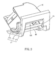
- the first fixed blocks 172 and the first slot 171 are L-shaped (as shown in FIG. 3 ) in association with a recess 91 of a top rail 90. (The recess 91 is open at both a bottom and a lateral side of the top rail 90.)
- the box 10 has a flexible locking portion 18 on a side opposite the fixed locking portion 17.
- the flexible locking portion 18 has two second blocks 182, a second slot 181 between the second blocks 182, and a flexible block 183.
- the second slot 181 is a L-shaped slot.
- One of the second blocks 182 is adjacent to the front side of the box 10 (The front side has the first opening 12 thereon.) the flexible block 183 is opposite the second slot 181 and distal to the front side of the box 10 than the second fixed block 182. (The front side has the first opening 12 thereon.)
- the flexible block 183 has a shape complementary to an inner space of the top rail 90.
- the flexible block 183 has a hollow portion that the flexible block 183 may be compressed by an external pressure and tends to eject out when the pressure is out (as shown in FIG. 4 ).
- the wear-resisted member 20 is a metal piece or a hard plastic piece having a high wear-resisting property. Opposite ends of the wear-resisted member 20 are engaged with the slots 141 of the box 10 that the wear-resisted member 20 covers the guide portion 14 to let the cord leaning thereon.
- a surface of the wear-resisted member 20 where the cord leans includes a first curved surface 21, a flat surface 22, a second curved surface 23, and a slope 24 (as shown in FIG. 8 ). The first curved surface 21 and the second curved surface 23 may reduce the friction when the cord moves on the wear-resisted member 20.
- the first toothed portion 16 of the box 10 co-acts with the slope 24 of the wear-resisted member 20 to form a self-lock angle.
- the self lock angle works according to a wedge principle for a self-lock action.
- An angle of the self-lock angle is between 32 degrees and 5 degrees.
- the movable driving wheel 30, which is made of a wear-resisting material, has a second toothed portion 31 on an outer side.
- the movable driving wheel 30 is received in the chamber 11 of the box 10 with the second toothed portion 31 engaged with the first toothed portion 16 of the box 10 (as shown in FIG. 2 ) that the movable driving wheel 30 moves along the first toothed portion 16 between a lock position and a release position.
- the poles 40 which are made of a wear-resisting material, are inserted into the through holes 15 with a constant interval that the poles 40 divides the first opening 12 into several sub-openings 121 and restricts the movable driving wheel 30 in the chamber 11 of the box 10 (as shown in FIG. 2 ).
- the assembled cord lock 100 is mounted on the recess 91 of the top rail 90, and the assembling way includes: putting the box 10 in a tilting position into the recess 91 with the first slot 171 engaged with a sidewall of the recess 91 that the first fixed blocks 172 are engaged with an inner side and an outer side of the sidewall of the recess 91 (as shown in FIG. 5 ), and then pushing the box 10 to have the other side thereof entering the recess 91 that the flexible block 183 is compressed by the sidewall of the recess 91 first to let the flexible block 183 entering the recess 91, and then the flexible block 183 will eject out to be stopped by the sidewall when the second slot 181 is engaged with the sidewall.
- the second fixed block 182 is complementary to the space inside the top rail 90, it could help the box 10 fixed in the recess 91 of the top rail 90 firmly.
- the fixed locking portion 17 and the guide portion 14 on the same side, the fixed locking portion 17 has a greater strength to sustain the force of the cord.
- the present invention provides the box 10 with the fixed locking portion 17 and the flexible locking portion 18 to provide a fixed side for fixed engagement and a flexible side for flexible engagement that would provide an easier way to assemble the box 10 on the top rail 90.
- the fixed locking portions are engaged with the top rail first, and then the flexible locking portion is pushed into the recess to complete the assembling work.
- the fixed locking portion 17 has a greater hardness and is on the same side with the wear-resisted device 20 that could sustain more pressure of the cord 80 exerting on the box 10 and help the box 10 fixed on the top rail 90 firmly.
- the wear-resisted device 20 of the present invention is a plate-like member, and the curvature of the convex portion 42 of the guide portion 14 is smaller than that of the movable driving wheel 30 (which means the driving device has a curvature diameter greater than that of the movable driving wheel) that the slope 24 of the wear-resisted device 20 may provide a greater-area support to the cord 80 when the cord 80 is clipped.
- the present invention provides a greater clipping force to prevent the cord from loosing.
- a cord lock of the second preferred embodiment of the present invention which is similar to the first preferred embodiment, except that a first slot 171 A and two first fixed blocks 172 are straight to match the sidewall of a recess 91 of an top rail 90 (the recess 91 only opens on a bottom of the top rail 90).
Landscapes
- Engineering & Computer Science (AREA)
- Structural Engineering (AREA)
- Architecture (AREA)
- Civil Engineering (AREA)
- Blinds (AREA)
- Curtains And Furnishings For Windows Or Doors (AREA)
Description
- The present invention relates to a window-covering product and more particularly, to a cord lock of a window blinds or shades.
- Traditionally, a conventional cord lock of a window blinds or shade includes a box mounted on the top rail of the window blinds or shade, a fixed pulley provided in the box, and a movable driving wheel provided in the box to lock or release a cord that operating of the cord may control moving up, down and stop of window blinds (or a shade).
- The conventional box, however, is fixed to a recess on the top rail that a L-shaped iron plate and screws are incorporated to fix the box on the top rail. This is a complex fixing way that the consumers are hard to do the assembly and disassembly work by himself/herself. To fix the above drawback,
U.S. patents 4,945,970 and7,117,920 taught the box is provided with two retractable locking blocks on opposite sides to be engage with the recess. The locking blocks are pressed inwards while put the box onto the top rail, and then while the box is completely placed in the recess of the top rail that the locking blocks will jump out automatically to secure the box to the top rail. However, it is very hard for the removable box, the fixed pulley, and the movable driving wheel to resist the force that user exerts on the cord and the weight of the cord and the window blinds or shade. As a result, the box may get loosed over time, or even disengaged with the recess. -
US-2005/0224192 discloses a pull cord control device for Venetian blind comprising a mounting body made up of an engagement piece having symmetrical registration posts for positioning rollers to be mounted thereto, and a limiting piece equipped with a pair of teeth racks symmetrically extending at both sides thereon in mesh with a control gear disposed at one side thereof to define a confinement space there-between for a coupling post with an embossed mounted thereto to be located in the middle thereof. A U-shaped groove is vertically indented at the inner side of the limiting piece therein for a U-shaped and metallic protection rod to be located therein and abutted against the upper edge of the confinement space thereof. A decoration lid of an oval shape with a pull-cord passage slot disposed thereon is integrally formed at one end of the limiting piece thereof with the protection rod exposed precisely at the inner lower edge of the pull-cord passage slot thereof. A cover having coupling holes to be registered with the limiting body thereof is provided with a plane abutting facet to be precisely abutted against the inner upper edge of the decoration lid thereby.; Thus, a pull cord guided through the upper edge of the protection rod before suspended downwards through the pull-cord passage slot of the decoration lid is refrained from directly rubbing against the frame edges of the pull-cord passage slot when drawn to any sides therein to fold/unfold the Venetian blind thereof.WO01/42612 -
US 2007/0102125 discloses a sliding wheel unit for a blind, which comprises a base member, provided with an exit hole in a rear wall and a friction member, provided with a circumferential wall defining a center hole for a pull rope to extend out, a position edge formed at one side and a bottom wall at the other side. After the friction member is inserted in the exit hole of the base member, the position edge and the bottom wall of the friction member contacts respectively the outer side and the inner side of the wall of the center hole of the base member to keep the friction member stable in place. - Besides, when the cord is pulled downward or swung right and left, it could move the movable driving wheel between a release position, in which the movable driving wheel keeps a distance from the fixed pulley, and a lock position, in which the movable driving wheel touches the fixed pulley. In the release position, the blinds (or the shade) are free to move, and in the lock position, the blinds (or the shade) are secured.
- However, while in a lock position, the movable driving wheel only has one point touching the fixed pulley that it provides insufficient force to secure the cord. As a result, the cord may get loosed or slipped from the fixed wheel because of the weight of the blinds or the shade.
- The primary objective of the present invention is to provide a cord lock of a window covering (window blinds or shade), which has an easier way to assembly and disassembly, and the cord lock is firmly mounted on the window covering.
- The secondary objective of the present invention is to provide a cord lock of a window blinds or shade, which can provide a firm cord lock while controling the window covering.
- To achieve these objectives of the present invention, a cord lock of a window covering according to
claim 1 is presented. -
-
FIG. 1 is an exploded view of a first preferred embodiment of the present invention; -
FIG. 2 is a perspective view of the first preferred embodiment of the present invention; -
FIG. 3 is another perspective view of the first preferred embodiment of the present invention; -
FIG. 4 is the third perspective view of first the preferred embodiment of the present invention; -
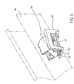
FIG. 5 is a perspective view of the first preferred embodiment of the present invention, showing the cord lock mounted on the top rail; -
FIG. 6 is the fourth perspective view of the first preferred embodiment of the present invention before installation; -
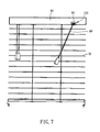
FIG. 7 is a perspective view of a window blinds or shade, on which the cord lock of the present invention is mounted; -
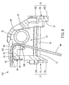
FIG. 8 andFIG. 9 are sectional views of the first preferred embodiment of the present invention, showing the actions of the cord lock; -
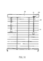
FIG. 10 is a perspective view of a window blinds or shade, on which the cord lock of the present invention is mounted; -
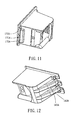
FIG. 11 is a perspective view of a second preferred embodiment of the present invention; -
FIG. 12 is another perspective view of the second preferred embodiment of the present invention; and -
FIG. 13 is a perspective view of the second preferred embodiment of the present invention, showing the cord lock mounted on the top rail. - Referring to
FIGS. 1 to 10 , acord lock 100 of a window covering (window blinds or shade) of the first preferred embodiment of the present invention includes abox 10, a wear-resistedmember 20, a movabledriving wheel 30, and a plurality ofpoles 40. - The
box 10 has achamber 11 therein, afirst opening 12 on a front side communicated with thechamber 11, and second opening 13 on a back side thereof communicated with thechamber 11. Thebox 10 further is provided with aguide portion 14 on a sidewall of thesecond opening 13. Theguide portion 14 has aconvex portion 142 and twoslots 141. Theconvex portion 142 has a curvature smaller than that of the movabledriving wheel 30. Thebox 10 further has a firstcurved portion 19A and a second curved portion 19b on opposite sides of the guide portion 14 (as shown inFIG. 4 ) that may reduce a friction when a cord enter thebox 10 via the opposite sides without touching theguide portion 14. Thebox 10 is provided with a plurality of throughholes 15 on opposite sidewalls of thefirst opening 12, and afirst toothed portion 16 on a sidewall of thechamber 11. Thefirst toothed portion 16 is opposite theguide portion 14. Thebox 10 has a fixedlocking portion 17 on an outer side with theguide portion 14. Thefixed locking portion 17 includes two firstfixed blocks 172 and afirst slot 171 between the firstfixed blocks 172. The firstfixed blocks 172 and thefirst slot 171 are L-shaped (as shown inFIG. 3 ) in association with arecess 91 of atop rail 90. (Therecess 91 is open at both a bottom and a lateral side of thetop rail 90.) Thebox 10 has aflexible locking portion 18 on a side opposite the fixedlocking portion 17. Theflexible locking portion 18 has twosecond blocks 182, asecond slot 181 between thesecond blocks 182, and aflexible block 183. Thesecond slot 181 is a L-shaped slot. One of thesecond blocks 182 is adjacent to the front side of the box 10 (The front side has the first opening 12 thereon.) theflexible block 183 is opposite thesecond slot 181 and distal to the front side of thebox 10 than the second fixedblock 182. (The front side has thefirst opening 12 thereon.) Theflexible block 183 has a shape complementary to an inner space of thetop rail 90. Theflexible block 183 has a hollow portion that theflexible block 183 may be compressed by an external pressure and tends to eject out when the pressure is out (as shown inFIG. 4 ). - The wear-resisted
member 20 is a metal piece or a hard plastic piece having a high wear-resisting property. Opposite ends of the wear-resistedmember 20 are engaged with theslots 141 of thebox 10 that the wear-resistedmember 20 covers theguide portion 14 to let the cord leaning thereon. A surface of the wear-resistedmember 20 where the cord leans includes a firstcurved surface 21, aflat surface 22, a secondcurved surface 23, and a slope 24 (as shown inFIG. 8 ). The firstcurved surface 21 and the secondcurved surface 23 may reduce the friction when the cord moves on the wear-resistedmember 20. The firsttoothed portion 16 of thebox 10 co-acts with theslope 24 of the wear-resistedmember 20 to form a self-lock angle. The self lock angle works according to a wedge principle for a self-lock action. An angle of the self-lock angle is between 32 degrees and 5 degrees. - The
movable driving wheel 30, which is made of a wear-resisting material, has a secondtoothed portion 31 on an outer side. Themovable driving wheel 30 is received in thechamber 11 of thebox 10 with the secondtoothed portion 31 engaged with the firsttoothed portion 16 of the box 10 (as shown inFIG. 2 ) that themovable driving wheel 30 moves along the firsttoothed portion 16 between a lock position and a release position. - The
poles 40, which are made of a wear-resisting material, are inserted into the throughholes 15 with a constant interval that thepoles 40 divides thefirst opening 12 intoseveral sub-openings 121 and restricts themovable driving wheel 30 in thechamber 11 of the box 10 (as shown inFIG. 2 ). - Above are the elements of the
cord lock 100 of the first embodiment of the present invention, and we will describe the way of assembling the elements and the function of the present invention as follows. - First, the assembled
cord lock 100 is mounted on therecess 91 of thetop rail 90, and the assembling way includes: putting thebox 10 in a tilting position into therecess 91 with thefirst slot 171 engaged with a sidewall of therecess 91 that the first fixedblocks 172 are engaged with an inner side and an outer side of the sidewall of the recess 91 (as shown inFIG. 5 ), and then pushing thebox 10 to have the other side thereof entering therecess 91 that theflexible block 183 is compressed by the sidewall of therecess 91 first to let theflexible block 183 entering therecess 91, and then theflexible block 183 will eject out to be stopped by the sidewall when thesecond slot 181 is engaged with the sidewall. Because the secondfixed block 182 is complementary to the space inside thetop rail 90, it could help thebox 10 fixed in therecess 91 of thetop rail 90 firmly. With the fixed lockingportion 17 and theguide portion 14 on the same side, the fixed lockingportion 17 has a greater strength to sustain the force of the cord. - Next, inserting a
cord 80 connecting a window covering (window blinds or shade) into thebox 10 via thesecond opening 13 and through a space between the wear-resisteddevice 20 and themovable driving wheel 30, and then going out of thebox 10 via the first opening 12 (as shown inFIG. 6 ) for manipulation. - To move the window covering up and down, one may hold the
cord 80 left out of thebox 10 to the left (as shown inFIG. 7 andFIG. 8 ) to move thecord 80 will toward the wear-resisteddevice 20 and away from themovable driving wheel 30 that themovable driving wheel 30 will roll downward because of the weight of itself to the release position (as shown inFIG. 9 ). In the release position, themovable driving wheel 30 moves off the wear-resisteddevice 20 that thecord 80 is no longer locked by themovable driving wheel 30, and thecord 80 is free to pull or release to move the window covering 70. - To fix the window covering 70, one may hold the
cord 80 straight (as shown inFIG. 9 ) and release thecord 80 that thecord 80 moves themovable driving wheel 30 upward to the lock position (as shown inFIG. 8 ), in which theslope 24 of the wear-resisteddevice 20 and themovable driving wheel 30 clip thecord 80 therebetween to secure thecords 80. Because both of the wear-resisteddevice 20 and themovable driving wheel 30 have hard smooth surfaces to touch each other, it could reduce the wear of thecord 80 to prolong the life of thecord 80. - The present invention provides the
box 10 with the fixed lockingportion 17 and theflexible locking portion 18 to provide a fixed side for fixed engagement and a flexible side for flexible engagement that would provide an easier way to assemble thebox 10 on thetop rail 90. (The fixed locking portions are engaged with the top rail first, and then the flexible locking portion is pushed into the recess to complete the assembling work.) Besides, the fixed lockingportion 17 has a greater hardness and is on the same side with the wear-resisteddevice 20 that could sustain more pressure of thecord 80 exerting on thebox 10 and help thebox 10 fixed on thetop rail 90 firmly. - Besides, the wear-resisted
device 20 of the present invention is a plate-like member, and the curvature of the convex portion 42 of theguide portion 14 is smaller than that of the movable driving wheel 30 (which means the driving device has a curvature diameter greater than that of the movable driving wheel) that theslope 24 of the wear-resisteddevice 20 may provide a greater-area support to thecord 80 when thecord 80 is clipped. To compare with the conventional device that the cord is clipped by point, the present invention provides a greater clipping force to prevent the cord from loosing. - As shown in
FIGS. 11 to FIG. 13 , a cord lock of the second preferred embodiment of the present invention, which is similar to the first preferred embodiment, except that afirst slot 171 A and two first fixedblocks 172 are straight to match the sidewall of arecess 91 of an top rail 90 (therecess 91 only opens on a bottom of the top rail 90). There are twoflexible blocks 183 in the second preferred embodiment. It could achieve the same function. - Although particular embodiments of the invention have been described in detail for purposes of illustration, various modifications and enhancements may be made without departing from the scope of the invention. as defined by the appended claims.
Claims (13)
- A cord lock of a window covering (100), comprising:a box (10) having a chamber (11) therein, an guide portion (14) on an outer side, a first opening (12) communicated with the chamber (11) for a cord (80) exiting the box (10), a second opening (13) opposite the first opening (12) for the cord (80) entering the box (10), a fixed locking portion (17) on the outer side, and a flexible locking portion (18) opposite the fixed locking portion (17); anda movable driving wheel (30), which is received in the chamber (11) of the box (10), to be moved between a lock position, in which the movable driving wheel (30) is moved toward the guide portion (14) to clip the cord (80) therebetween, and a release position, in which the movable driving wheel (30) is moved away from the guide portion (14) to release the cord (80)characterized in that further comprising,a wear-resisted member (20), which is is a plate made of a wear-resisting material, provided on the guide portion (14) to rest the cord (80) thereon, to cover the guide portion (14), andwherein the guide portion (14) further includes a convex portion (142) having a curvature smaller than that of the movable driving wheel (30).
- The cord lock of the window covering (100) as claimed in claim 1, wherein the fixed locking portion (17) includes two first fixed blocks (172) and a first slot (171) between the first fixed blocks (172), and the flexible locking portion (18) includes a second fixed block (182), a flexible block (183), and a second slot (181) between the second fixed block (182) and flexible block (183), further wherein the flexible block (183) has a hollow portion that the flexible block (183) is compressed by an external pressure.
- The cord lock of the window covering (100) as claimed in claim 2, wherein the second fixed block (182) is received in the second slot (181) and proximal to the first opening (12), and the flexible block (18) is received in the second slot (181) and distal to the first opening (12).
- The cord lock of the window covering (100) as claimed in claim 1, further comprising a plurality of poles (40), wherein the box (10) has a plurality of through holes (15) on opposite sidewalls of the first opening (12), and the poles (40) have opposite ends inserted into the through holes (15) to divide first opening (12) into several sub-openings.
- The cord lock of the window covering (100) as claimed in claim 4, wherein the poles (40) are made of a wear-resisting hard material.
- The cord lock of the window covering (100) as claimed in claim 1, wherein the box (10) has a first toothed portion (16) on a sidewall of the chamber (11), and the movable driving wheel (30) has a second toothed portion (31) touching the first toothed portion (16), further wherein the second toothed portion (31) is moved on the first toothed portion (16) when the movable driving wheel (30) is moved between the lock position and the release position.
- The cord lock of the window covering (100) as claimed in claim 1, wherein the guide portion (14) has two slots (141) to engage the wear-resisted member (20), and a surface of the wear-resisted member where the cord (80) leans thereon includes a first curved surface (21), a flat surface (22), a second curved surface (23), and a slope (24).
- The cord lock of the window covering (100) as claimed in claim 7, wherein the box (10) has a first toothed portion (16) on an inner side, and a self-lock angle is formed between the first toothed portion (16) and the slope (24) of the wear-resisted member (20) to generate a self-lock action according to a wedge principle.
- The cord lock of the window covering (100) as claimed in claim 8, wherein the self-lock angle is between 32 degrees and 5 degrees.
- The cord lock of the window covering (100) as claimed in claim 1, wherein the box (10) has a first curved portion (19a) and a second curved portion (19b) at opposite sides of the guide portion (14) to support the cord (80) when the cord (80) does not pass the driving device (14).
- The cord lock of the window covering (100) as claimed in claim 2, wherein the first slot (171) and the first fixed blocks (172) are L-shaped members.
- The cord lock of the window covering (100) as claimed in claim 2, wherein the first slot (171) and the first fixed blocks (172) are straight members.
- The cord lock of the window covering (100) as claimed in claim 1, wherein the fixed locking portion (17) and the guide portion (14) are on the same side of the box (10).
Applications Claiming Priority (1)
| Application Number | Priority Date | Filing Date | Title |
|---|---|---|---|
| TW97223704U TWM361554U (en) | 2008-12-30 | 2008-12-30 | Braking structure for pull cord of window curtain |
Publications (3)
| Publication Number | Publication Date |
|---|---|
| EP2204528A2 EP2204528A2 (en) | 2010-07-07 |
| EP2204528A3 EP2204528A3 (en) | 2014-03-05 |
| EP2204528B1 true EP2204528B1 (en) | 2016-01-06 |
Family
ID=42105857
Family Applications (1)
| Application Number | Title | Priority Date | Filing Date |
|---|---|---|---|
| EP09003766.4A Not-in-force EP2204528B1 (en) | 2008-12-30 | 2009-03-16 | Cord lock of window coverings |
Country Status (3)
| Country | Link |
|---|---|
| EP (1) | EP2204528B1 (en) |
| AU (1) | AU2009201071B2 (en) |
| TW (1) | TWM361554U (en) |
Families Citing this family (3)
| Publication number | Priority date | Publication date | Assignee | Title |
|---|---|---|---|---|
| TWI572771B (en) * | 2012-06-15 | 2017-03-01 | Tachikawa Blind Mfg | The sun shading device and its manufacturing method |
| CN205990871U (en) * | 2016-05-31 | 2017-03-01 | 亿丰综合工业股份有限公司 | Drawstring locking mechanism for curtains |
| JP6895983B2 (en) * | 2016-09-14 | 2021-06-30 | 立川ブラインド工業株式会社 | Braking device and shielding device using it |
Family Cites Families (14)
| Publication number | Priority date | Publication date | Assignee | Title |
|---|---|---|---|---|
| US4180118A (en) * | 1978-07-13 | 1979-12-25 | Hunter Douglas International N.V. | Cord lock mechanism for venetian blind |
| US4463791A (en) * | 1983-01-24 | 1984-08-07 | Marathon Manufacturing Company | Venetian blind cord lock for up to eight lift cords |
| US4488588A (en) * | 1983-01-24 | 1984-12-18 | Marathon Manufacturing Company | Cord lock for venetian blind |
| JPH0328710Y2 (en) * | 1985-02-09 | 1991-06-19 | ||
| US4945970A (en) | 1989-06-28 | 1990-08-07 | Norbert Marocco | Cord lock unit for drape or blind assembly |
| AU741794B2 (en) * | 1998-01-14 | 2001-12-06 | Hunter Douglas International N.V. | Cord-lock |
| JP2000265758A (en) * | 1999-03-15 | 2000-09-26 | Tachikawa Blind Mfg Co Ltd | Solar shading device |
| WO2001042612A1 (en) * | 1999-12-08 | 2001-06-14 | Rowley Company, Inc. | Improved cord lock assembly and manufacturing method |
| CA2299030C (en) * | 2000-02-18 | 2002-09-10 | Tai-Long Huang | Cord control device for a venetian blind to control raising and lowering of the slats |
| GB2402602A (en) * | 2003-06-10 | 2004-12-15 | Tser-Wen Chou | A drawstring mechanism for a curtain or a blind |
| AU2004203612B2 (en) | 2003-09-02 | 2009-07-30 | Hunter Douglas Industries B.V. | A cord lock |
| TWM253300U (en) * | 2004-04-12 | 2004-12-21 | Ching Feng Home Fashions Co | Pull cord control device for venetian blind |
| US20060207729A1 (en) * | 2005-03-17 | 2006-09-21 | Fu-Lai Yu | Control mechanism for a window covering |
| US20070102125A1 (en) * | 2005-11-09 | 2007-05-10 | Nien Made Enterprise Co., Ltd. | Sliding wheel unit for a blind |
-
2008
- 2008-12-30 TW TW97223704U patent/TWM361554U/en not_active IP Right Cessation
-
2009
- 2009-03-16 EP EP09003766.4A patent/EP2204528B1/en not_active Not-in-force
- 2009-03-18 AU AU2009201071A patent/AU2009201071B2/en not_active Ceased
Also Published As
| Publication number | Publication date |
|---|---|
| TWM361554U (en) | 2009-07-21 |
| EP2204528A3 (en) | 2014-03-05 |
| AU2009201071A1 (en) | 2010-07-15 |
| EP2204528A2 (en) | 2010-07-07 |
| AU2009201071B2 (en) | 2012-08-02 |
Similar Documents
| Publication | Publication Date | Title |
|---|---|---|
| EP2753777B1 (en) | Retractable and extendable covering device | |
| US20100236731A1 (en) | Cord lock of window coverings | |
| CN105074114B (en) | Position locking for roller-supported building panels | |
| US7900680B2 (en) | Head rail assembly | |
| US20120291964A1 (en) | Blind assembly with two blind head rail | |
| KR200483878Y1 (en) | Curtain rail assembly with easy insertion and separation | |
| US11560743B2 (en) | Window balance systems | |
| EP2545241B1 (en) | Door screen system comprising two retractable door screens | |
| JP6126898B2 (en) | sash | |
| US7159638B2 (en) | Pull cord control device for Venetian blind | |
| EP2204528A2 (en) | Cord lock of window coverings | |
| US8136568B2 (en) | Retractable arched window covering | |
| JP4474623B2 (en) | Guide rail structure of shutter device | |
| EP1781886B1 (en) | Improved rolling mosquito net provided with foldaway guides | |
| KR200205902Y1 (en) | A bratck for the blinds | |
| CN201367845Y (en) | Braking structure for curtain pull rope | |
| JP4020788B2 (en) | Shutter locking device | |
| JPH0328710Y2 (en) | ||
| JP2005146642A (en) | Horizontally retractable screen door | |
| KR200237001Y1 (en) | Locking Tool for Roller-Type Moth-proof Net | |
| GB2582960A (en) | A window/door covering arrangement | |
| KR101330056B1 (en) | Code holder | |
| EP4689341A1 (en) | End element applied to the lower edge of the flexible sheet of a roller blind and roller blind using said end element | |
| JP2006169871A (en) | Deflection regulating structure and deflection regulating member of shutter curtain | |
| KR20150002674U (en) | Attachment structure between a clutch and a cover in roll blind system |
Legal Events
| Date | Code | Title | Description |
|---|---|---|---|
| PUAI | Public reference made under article 153(3) epc to a published international application that has entered the european phase |
Free format text: ORIGINAL CODE: 0009012 |
|
| 17P | Request for examination filed |
Effective date: 20090316 |
|
| AK | Designated contracting states |
Kind code of ref document: A2 Designated state(s): AT BE BG CH CY CZ DE DK EE ES FI FR GB GR HR HU IE IS IT LI LT LU LV MC MK MT NL NO PL PT RO SE SI SK TR |
|
| AX | Request for extension of the european patent |
Extension state: AL BA RS |
|
| PUAL | Search report despatched |
Free format text: ORIGINAL CODE: 0009013 |
|
| AK | Designated contracting states |
Kind code of ref document: A3 Designated state(s): AT BE BG CH CY CZ DE DK EE ES FI FR GB GR HR HU IE IS IT LI LT LU LV MC MK MT NL NO PL PT RO SE SI SK TR |
|
| AX | Request for extension of the european patent |
Extension state: AL BA RS |
|
| RIC1 | Information provided on ipc code assigned before grant |
Ipc: E06B 9/324 20060101AFI20140129BHEP |
|
| AKX | Designation fees paid |
Designated state(s): AT BE BG CH CY CZ DE DK EE ES FI FR GB GR HR HU IE IS IT LI LT LU LV MC MK MT NL NO PL PT RO SE SI SK TR |
|
| GRAP | Despatch of communication of intention to grant a patent |
Free format text: ORIGINAL CODE: EPIDOSNIGR1 |
|
| INTG | Intention to grant announced |
Effective date: 20150723 |
|
| GRAS | Grant fee paid |
Free format text: ORIGINAL CODE: EPIDOSNIGR3 |
|
| GRAA | (expected) grant |
Free format text: ORIGINAL CODE: 0009210 |
|
| AK | Designated contracting states |
Kind code of ref document: B1 Designated state(s): AT BE BG CH CY CZ DE DK EE ES FI FR GB GR HR HU IE IS IT LI LT LU LV MC MK MT NL NO PL PT RO SE SI SK TR |
|
| REG | Reference to a national code |
Ref country code: GB Ref legal event code: FG4D |
|
| REG | Reference to a national code |
Ref country code: CH Ref legal event code: EP |
|
| REG | Reference to a national code |
Ref country code: IE Ref legal event code: FG4D |
|
| REG | Reference to a national code |
Ref country code: AT Ref legal event code: REF Ref document number: 769029 Country of ref document: AT Kind code of ref document: T Effective date: 20160215 |
|
| REG | Reference to a national code |
Ref country code: DE Ref legal event code: R096 Ref document number: 602009035498 Country of ref document: DE |
|
| REG | Reference to a national code |
Ref country code: FR Ref legal event code: PLFP Year of fee payment: 8 |
|
| REG | Reference to a national code |
Ref country code: NL Ref legal event code: FP |
|
| REG | Reference to a national code |
Ref country code: LT Ref legal event code: MG4D |
|
| REG | Reference to a national code |
Ref country code: AT Ref legal event code: MK05 Ref document number: 769029 Country of ref document: AT Kind code of ref document: T Effective date: 20160106 |
|
| PG25 | Lapsed in a contracting state [announced via postgrant information from national office to epo] |
Ref country code: FI Free format text: LAPSE BECAUSE OF FAILURE TO SUBMIT A TRANSLATION OF THE DESCRIPTION OR TO PAY THE FEE WITHIN THE PRESCRIBED TIME-LIMIT Effective date: 20160106 Ref country code: IT Free format text: LAPSE BECAUSE OF FAILURE TO SUBMIT A TRANSLATION OF THE DESCRIPTION OR TO PAY THE FEE WITHIN THE PRESCRIBED TIME-LIMIT Effective date: 20160106 Ref country code: NO Free format text: LAPSE BECAUSE OF FAILURE TO SUBMIT A TRANSLATION OF THE DESCRIPTION OR TO PAY THE FEE WITHIN THE PRESCRIBED TIME-LIMIT Effective date: 20160406 Ref country code: ES Free format text: LAPSE BECAUSE OF FAILURE TO SUBMIT A TRANSLATION OF THE DESCRIPTION OR TO PAY THE FEE WITHIN THE PRESCRIBED TIME-LIMIT Effective date: 20160106 Ref country code: GR Free format text: LAPSE BECAUSE OF FAILURE TO SUBMIT A TRANSLATION OF THE DESCRIPTION OR TO PAY THE FEE WITHIN THE PRESCRIBED TIME-LIMIT Effective date: 20160407 Ref country code: HR Free format text: LAPSE BECAUSE OF FAILURE TO SUBMIT A TRANSLATION OF THE DESCRIPTION OR TO PAY THE FEE WITHIN THE PRESCRIBED TIME-LIMIT Effective date: 20160106 |
|
| PG25 | Lapsed in a contracting state [announced via postgrant information from national office to epo] |
Ref country code: PT Free format text: LAPSE BECAUSE OF FAILURE TO SUBMIT A TRANSLATION OF THE DESCRIPTION OR TO PAY THE FEE WITHIN THE PRESCRIBED TIME-LIMIT Effective date: 20160506 Ref country code: LT Free format text: LAPSE BECAUSE OF FAILURE TO SUBMIT A TRANSLATION OF THE DESCRIPTION OR TO PAY THE FEE WITHIN THE PRESCRIBED TIME-LIMIT Effective date: 20160106 Ref country code: PL Free format text: LAPSE BECAUSE OF FAILURE TO SUBMIT A TRANSLATION OF THE DESCRIPTION OR TO PAY THE FEE WITHIN THE PRESCRIBED TIME-LIMIT Effective date: 20160106 Ref country code: IS Free format text: LAPSE BECAUSE OF FAILURE TO SUBMIT A TRANSLATION OF THE DESCRIPTION OR TO PAY THE FEE WITHIN THE PRESCRIBED TIME-LIMIT Effective date: 20160506 Ref country code: SE Free format text: LAPSE BECAUSE OF FAILURE TO SUBMIT A TRANSLATION OF THE DESCRIPTION OR TO PAY THE FEE WITHIN THE PRESCRIBED TIME-LIMIT Effective date: 20160106 Ref country code: AT Free format text: LAPSE BECAUSE OF FAILURE TO SUBMIT A TRANSLATION OF THE DESCRIPTION OR TO PAY THE FEE WITHIN THE PRESCRIBED TIME-LIMIT Effective date: 20160106 Ref country code: LV Free format text: LAPSE BECAUSE OF FAILURE TO SUBMIT A TRANSLATION OF THE DESCRIPTION OR TO PAY THE FEE WITHIN THE PRESCRIBED TIME-LIMIT Effective date: 20160106 |
|
| REG | Reference to a national code |
Ref country code: DE Ref legal event code: R097 Ref document number: 602009035498 Country of ref document: DE |
|
| PG25 | Lapsed in a contracting state [announced via postgrant information from national office to epo] |
Ref country code: MC Free format text: LAPSE BECAUSE OF FAILURE TO SUBMIT A TRANSLATION OF THE DESCRIPTION OR TO PAY THE FEE WITHIN THE PRESCRIBED TIME-LIMIT Effective date: 20160106 Ref country code: EE Free format text: LAPSE BECAUSE OF FAILURE TO SUBMIT A TRANSLATION OF THE DESCRIPTION OR TO PAY THE FEE WITHIN THE PRESCRIBED TIME-LIMIT Effective date: 20160106 Ref country code: DK Free format text: LAPSE BECAUSE OF FAILURE TO SUBMIT A TRANSLATION OF THE DESCRIPTION OR TO PAY THE FEE WITHIN THE PRESCRIBED TIME-LIMIT Effective date: 20160106 |
|
| REG | Reference to a national code |
Ref country code: CH Ref legal event code: PL |
|
| PLBE | No opposition filed within time limit |
Free format text: ORIGINAL CODE: 0009261 |
|
| STAA | Information on the status of an ep patent application or granted ep patent |
Free format text: STATUS: NO OPPOSITION FILED WITHIN TIME LIMIT |
|
| PG25 | Lapsed in a contracting state [announced via postgrant information from national office to epo] |
Ref country code: SK Free format text: LAPSE BECAUSE OF FAILURE TO SUBMIT A TRANSLATION OF THE DESCRIPTION OR TO PAY THE FEE WITHIN THE PRESCRIBED TIME-LIMIT Effective date: 20160106 Ref country code: RO Free format text: LAPSE BECAUSE OF FAILURE TO SUBMIT A TRANSLATION OF THE DESCRIPTION OR TO PAY THE FEE WITHIN THE PRESCRIBED TIME-LIMIT Effective date: 20160106 |
|
| 26N | No opposition filed |
Effective date: 20161007 |
|
| PG25 | Lapsed in a contracting state [announced via postgrant information from national office to epo] |
Ref country code: CH Free format text: LAPSE BECAUSE OF NON-PAYMENT OF DUE FEES Effective date: 20160331 Ref country code: LI Free format text: LAPSE BECAUSE OF NON-PAYMENT OF DUE FEES Effective date: 20160331 |
|
| PG25 | Lapsed in a contracting state [announced via postgrant information from national office to epo] |
Ref country code: BG Free format text: LAPSE BECAUSE OF FAILURE TO SUBMIT A TRANSLATION OF THE DESCRIPTION OR TO PAY THE FEE WITHIN THE PRESCRIBED TIME-LIMIT Effective date: 20160406 Ref country code: SI Free format text: LAPSE BECAUSE OF FAILURE TO SUBMIT A TRANSLATION OF THE DESCRIPTION OR TO PAY THE FEE WITHIN THE PRESCRIBED TIME-LIMIT Effective date: 20160106 |
|
| REG | Reference to a national code |
Ref country code: FR Ref legal event code: PLFP Year of fee payment: 9 |
|
| PG25 | Lapsed in a contracting state [announced via postgrant information from national office to epo] |
Ref country code: MT Free format text: LAPSE BECAUSE OF FAILURE TO SUBMIT A TRANSLATION OF THE DESCRIPTION OR TO PAY THE FEE WITHIN THE PRESCRIBED TIME-LIMIT Effective date: 20160106 |
|
| REG | Reference to a national code |
Ref country code: FR Ref legal event code: PLFP Year of fee payment: 10 |
|
| PGFP | Annual fee paid to national office [announced via postgrant information from national office to epo] |
Ref country code: NL Payment date: 20180322 Year of fee payment: 10 Ref country code: CZ Payment date: 20180302 Year of fee payment: 10 Ref country code: GB Payment date: 20180326 Year of fee payment: 10 Ref country code: LU Payment date: 20180322 Year of fee payment: 10 |
|
| PG25 | Lapsed in a contracting state [announced via postgrant information from national office to epo] |
Ref country code: HU Free format text: LAPSE BECAUSE OF FAILURE TO SUBMIT A TRANSLATION OF THE DESCRIPTION OR TO PAY THE FEE WITHIN THE PRESCRIBED TIME-LIMIT; INVALID AB INITIO Effective date: 20090316 Ref country code: CY Free format text: LAPSE BECAUSE OF FAILURE TO SUBMIT A TRANSLATION OF THE DESCRIPTION OR TO PAY THE FEE WITHIN THE PRESCRIBED TIME-LIMIT Effective date: 20160106 |
|
| PGFP | Annual fee paid to national office [announced via postgrant information from national office to epo] |
Ref country code: IE Payment date: 20180326 Year of fee payment: 10 Ref country code: BE Payment date: 20180322 Year of fee payment: 10 Ref country code: FR Payment date: 20180326 Year of fee payment: 10 |
|
| PG25 | Lapsed in a contracting state [announced via postgrant information from national office to epo] |
Ref country code: MK Free format text: LAPSE BECAUSE OF FAILURE TO SUBMIT A TRANSLATION OF THE DESCRIPTION OR TO PAY THE FEE WITHIN THE PRESCRIBED TIME-LIMIT Effective date: 20160106 Ref country code: TR Free format text: LAPSE BECAUSE OF FAILURE TO SUBMIT A TRANSLATION OF THE DESCRIPTION OR TO PAY THE FEE WITHIN THE PRESCRIBED TIME-LIMIT Effective date: 20160106 Ref country code: MT Free format text: LAPSE BECAUSE OF FAILURE TO SUBMIT A TRANSLATION OF THE DESCRIPTION OR TO PAY THE FEE WITHIN THE PRESCRIBED TIME-LIMIT Effective date: 20160331 |
|
| PGFP | Annual fee paid to national office [announced via postgrant information from national office to epo] |
Ref country code: DE Payment date: 20180328 Year of fee payment: 10 |
|
| REG | Reference to a national code |
Ref country code: DE Ref legal event code: R119 Ref document number: 602009035498 Country of ref document: DE |
|
| PG25 | Lapsed in a contracting state [announced via postgrant information from national office to epo] |
Ref country code: CZ Free format text: LAPSE BECAUSE OF NON-PAYMENT OF DUE FEES Effective date: 20190316 |
|
| REG | Reference to a national code |
Ref country code: NL Ref legal event code: MM Effective date: 20190401 |
|
| GBPC | Gb: european patent ceased through non-payment of renewal fee |
Effective date: 20190316 |
|
| PG25 | Lapsed in a contracting state [announced via postgrant information from national office to epo] |
Ref country code: LU Free format text: LAPSE BECAUSE OF NON-PAYMENT OF DUE FEES Effective date: 20190316 |
|
| REG | Reference to a national code |
Ref country code: BE Ref legal event code: MM Effective date: 20190331 |
|
| PG25 | Lapsed in a contracting state [announced via postgrant information from national office to epo] |
Ref country code: DE Free format text: LAPSE BECAUSE OF NON-PAYMENT OF DUE FEES Effective date: 20191001 Ref country code: IE Free format text: LAPSE BECAUSE OF NON-PAYMENT OF DUE FEES Effective date: 20190316 Ref country code: NL Free format text: LAPSE BECAUSE OF NON-PAYMENT OF DUE FEES Effective date: 20190401 Ref country code: GB Free format text: LAPSE BECAUSE OF NON-PAYMENT OF DUE FEES Effective date: 20190316 |
|
| PG25 | Lapsed in a contracting state [announced via postgrant information from national office to epo] |
Ref country code: BE Free format text: LAPSE BECAUSE OF NON-PAYMENT OF DUE FEES Effective date: 20190331 Ref country code: FR Free format text: LAPSE BECAUSE OF NON-PAYMENT OF DUE FEES Effective date: 20190331 |