EP2204506A2 - Cold water tank and water treatment apparatus having the same - Google Patents
Cold water tank and water treatment apparatus having the same Download PDFInfo
- Publication number
- EP2204506A2 EP2204506A2 EP20090164126 EP09164126A EP2204506A2 EP 2204506 A2 EP2204506 A2 EP 2204506A2 EP 20090164126 EP20090164126 EP 20090164126 EP 09164126 A EP09164126 A EP 09164126A EP 2204506 A2 EP2204506 A2 EP 2204506A2
- Authority
- EP
- European Patent Office
- Prior art keywords
- water
- tank body
- tank
- outlet pipe
- air vent
- Prior art date
- Legal status (The legal status is an assumption and is not a legal conclusion. Google has not performed a legal analysis and makes no representation as to the accuracy of the status listed.)
- Granted
Links
Images


Classifications
-
- E—FIXED CONSTRUCTIONS
- E03—WATER SUPPLY; SEWERAGE
- E03B—INSTALLATIONS OR METHODS FOR OBTAINING, COLLECTING, OR DISTRIBUTING WATER
- E03B11/00—Arrangements or adaptations of tanks for water supply
- E03B11/02—Arrangements or adaptations of tanks for water supply for domestic or like local water supply
- E03B11/06—Arrangements or adaptations of tanks for water supply for domestic or like local water supply with air regulators
-
- F—MECHANICAL ENGINEERING; LIGHTING; HEATING; WEAPONS; BLASTING
- F25—REFRIGERATION OR COOLING; COMBINED HEATING AND REFRIGERATION SYSTEMS; HEAT PUMP SYSTEMS; MANUFACTURE OR STORAGE OF ICE; LIQUEFACTION SOLIDIFICATION OF GASES
- F25D—REFRIGERATORS; COLD ROOMS; ICE-BOXES; COOLING OR FREEZING APPARATUS NOT OTHERWISE PROVIDED FOR
- F25D31/00—Other cooling or freezing apparatus
- F25D31/002—Liquid coolers, e.g. beverage cooler
-
- Y—GENERAL TAGGING OF NEW TECHNOLOGICAL DEVELOPMENTS; GENERAL TAGGING OF CROSS-SECTIONAL TECHNOLOGIES SPANNING OVER SEVERAL SECTIONS OF THE IPC; TECHNICAL SUBJECTS COVERED BY FORMER USPC CROSS-REFERENCE ART COLLECTIONS [XRACs] AND DIGESTS
- Y02—TECHNOLOGIES OR APPLICATIONS FOR MITIGATION OR ADAPTATION AGAINST CLIMATE CHANGE
- Y02A—TECHNOLOGIES FOR ADAPTATION TO CLIMATE CHANGE
- Y02A20/00—Water conservation; Efficient water supply; Efficient water use
-
- Y—GENERAL TAGGING OF NEW TECHNOLOGICAL DEVELOPMENTS; GENERAL TAGGING OF CROSS-SECTIONAL TECHNOLOGIES SPANNING OVER SEVERAL SECTIONS OF THE IPC; TECHNICAL SUBJECTS COVERED BY FORMER USPC CROSS-REFERENCE ART COLLECTIONS [XRACs] AND DIGESTS
- Y10—TECHNICAL SUBJECTS COVERED BY FORMER USPC
- Y10T—TECHNICAL SUBJECTS COVERED BY FORMER US CLASSIFICATION
- Y10T137/00—Fluid handling
- Y10T137/2931—Diverse fluid containing pressure systems
- Y10T137/3003—Fluid separating traps or vents
- Y10T137/3084—Discriminating outlet for gas
- Y10T137/309—Fluid sensing valve
- Y10T137/3099—Float responsive
-
- Y—GENERAL TAGGING OF NEW TECHNOLOGICAL DEVELOPMENTS; GENERAL TAGGING OF CROSS-SECTIONAL TECHNOLOGIES SPANNING OVER SEVERAL SECTIONS OF THE IPC; TECHNICAL SUBJECTS COVERED BY FORMER USPC CROSS-REFERENCE ART COLLECTIONS [XRACs] AND DIGESTS
- Y10—TECHNICAL SUBJECTS COVERED BY FORMER USPC
- Y10T—TECHNICAL SUBJECTS COVERED BY FORMER US CLASSIFICATION
- Y10T137/00—Fluid handling
- Y10T137/7287—Liquid level responsive or maintaining systems
- Y10T137/7293—Liquid excluding devices for gas inlet or outlets
-
- Y—GENERAL TAGGING OF NEW TECHNOLOGICAL DEVELOPMENTS; GENERAL TAGGING OF CROSS-SECTIONAL TECHNOLOGIES SPANNING OVER SEVERAL SECTIONS OF THE IPC; TECHNICAL SUBJECTS COVERED BY FORMER USPC CROSS-REFERENCE ART COLLECTIONS [XRACs] AND DIGESTS
- Y10—TECHNICAL SUBJECTS COVERED BY FORMER USPC
- Y10T—TECHNICAL SUBJECTS COVERED BY FORMER US CLASSIFICATION
- Y10T137/00—Fluid handling
- Y10T137/7287—Liquid level responsive or maintaining systems
- Y10T137/7358—By float controlled valve
- Y10T137/7423—Rectilinearly traveling float
Abstract
Description
- This application claims the priority of Korean Patent Application Nos.
2008-0136733 filed on December 30, 2008 2009-0054281 filed on June 18, 2009 - The present invention relates to a cold water tank and a water treatment apparatus having the same.
- Cold water tanks refer to devices, which are connected to or include cooling units to cool the water introduced therein, and drain the cooled water out of the tanks.
- Referring to
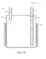
FIGS. 1A and1B , a cold water tank may include atank body 20 receiving and storing water, awater inlet pipe 30 provided at thetank body 20 to convey water into thetank body 20, and awater outlet pipe 40 provided at thetank body 20 to convey the water out of thetank body 20, and having anair vent hole 41 formed in its upper portion. - The water inlet
pipe 30, as shown inFIGS. 1A and1B , has its one end placed in the upper portion of thetank body 20, thereby facilitating water inflow into thetank body 20. Thewater outlet pipe 40 has its one end placed in the lower portion of thetank body 20, and this allows users to be provided with the water existing in the lower portion of thetank body 20 at a relatively low temperature. As depicted in the drawings, arefrigerant pipe 60 as a cooling unit is wound around the circumference of thetank body 20 to cool the water in thetank body 20. That is, the water, having flowed in thetank body 20 through thewater inlet pipe 30, is cooled by heat exchange with a refrigerant flowing in therefrigerant pipe 60. The water cooled in the above manner is discharged out of thetank body 20 through thewater outlet pipe 40. - While water is flowing into the
tank body 20 through the water inletpipe 30, as shown inFIG. 1A , the air within thetank body 20 passes through theair vent hole 41 in the upper portion of thewater outlet pipe 40 and exits out of thetank body 20 through thewater outlet pipe 40. As shown inFIG. 1B , if thetank body 20 is completely filled with water, all of the air in thetank body 20 exits through thewater outlet pipe 40 via theair vent hole 41. If, in this state, the water in the lower portion of thetank body 20 is discharged through thewater outlet pipe 40 to supply cooled water to a user, then the water in the upper portion of thetank body 20 undesirably passes through theair vent hole 41 and drains through thewater outlet pipe 40. - As described above, the water existing in the upper portion of the
tank body 20 may be different in temperature from the water existing in the lower portion of thetank body 20. That is, the water in the upper portion of thetank body 20 has a higher temperature than the water in the lower portion of thetank body 20. - Accordingly, as described with reference to
FIG. 1B , in the event that the water in the upper portion of thetank body 20 passes through theair vent hole 41 and drains through thewater outlet pipe 40, the water in the upper portion and the water in the lower portion, having different temperatures, may mix undesirably in thewater outlet pipe 40. That is, the water existing in the upper portion of thetank body 20 at a relatively high temperature may be supplied, mixed with the water existing in the lower portion of thetank body 20 at a relatively low temperature. This may result in the supply of water having a higher temperature than desired. - The above limitations may also be caused in water treatment apparatuses including the
cold water tank 10, such as water purifiers or water ionizers. - Accordingly, the present invention is directed to a cold water tank and a water treatment apparatus having the same, which substantially obviates one or more problems due to limitations and disadvantages of the related art.
- An aspect of the present invention provides a cold water tank and a water treatment apparatus having the same, which can prevent water in the upper portion of a tank body from draining into a water outlet pipe through an air vent hole in the water outlet pipe provided at a tank body of a cold water tank.
- An aspect of the present invention also provides a cold water tank and a water treatment apparatus having the same, which can prevent the water, existing in the lower portion of the tank body at a relatively low temperature, from mixing with the water existing in the upper portion of the tank body at relatively high temperature.
- An aspect of the present invention also provides a cold water tank and a water treatment apparatus having the same, which can supply water existing only in the lower portion of the tank body at a relatively low temperature to a user.
- A cold water tank associated with an exemplary embodiment may have the following features to realize at least one of the above aspects.
- The present invention is basically based on blocking an air vent hole in a water outlet pipe provided at a tank body of a cold water tank, by using a floating member.
- According to an aspect of the present invention, there is provided a cold water tank including: a tank body; a water inlet pipe provided at the tank body to convey water into the tank body; a water outlet pipe provided at the tank body to convey the water out of the tank body, and including an air vent hole; and a floating member movably provided at the water outlet pipe to block the air vent hole when the water filling the tank body reaches a height of the air vent hole.
- The water outlet pipe may be provided with a stopper preventing the floating member from descending to a predetermined height or lower.
- The tank body may be provided with a receiving part receiving the floating member as the floating member ascends, and the air vent hole may be formed at the same height as the receiving part, in the water outlet pipe.
- The receiving part may be provided with a blocking member including another air vent hole.
- The water inlet pipe may be connected to a water treatment apparatus including one or more water filters to convey water filtered through the water filters into the tank body.
- The water inlet pipe may be directly connected to an outlet of the last water filter among the one or more water filters, and the water in the tank body may drain out of the tank body through the water outlet pipe by the pressure of water discharged from the outlet of the last water filter.
- According to another aspect of the present invention, there is provided a water treatment apparatus including: a water source supplying water; and a cold water tank connected to the water supply source and receiving and discharging water by the pressure of water supplied from the water supply source.
- The water treatment apparatus may further include one or more water filters connected between the water supply source and the cold water tank, and the cold water tank may be connected to an outlet of the last water filter among the one or more water filters.
- The above and other aspects, features and other advantages of the present invention will be more clearly understood from the following detailed description taken in conjunction with the accompanying drawings, in which:
-
FIG. 1A illustrates a related art cold water tank when a tank body of the cold water tank is partially filled with water; -
FIG. 1B illustrates the related art cold water tank when the tank body of the cold water tank is completely filled with water; -
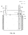
FIG. 2A illustrates a cold water tank according to an exemplary embodiment of the present invention, when a tank body of the cold water tank is partially filled with water; -
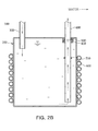
FIG. 2B illustrates the cold water tank ofFIG. 2A , when the tank body of the cold water tank is completely filled with water; -
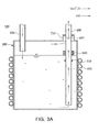
FIG. 3A illustrates a cold water tank according to another exemplary embodiment of the present invention, when a tank body of the cold water tank is partially filled with water; -
FIG. 3B illustrates the cold water tank ofFIG. 3A , when a tank body of the cold water tank is completely filled with water; -
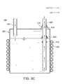
FIG. 3C illustrates a cold water tank according to another exemplary embodiment of the present invention, which includes a receiving part with a modified shape; -
FIG. 4A illustrates a cold water tank according to another exemplary embodiment of the present invention, when a tank body of the cold water tank is partially filled with water; -
FIG. 4B illustrates the cold water tank ofFIG. 4A , when the tank body of the cold water tank is completely filled with water; and -
FIG. 5 illustrates a water treatment apparatus according to an exemplary embodiment of the present invention, which includes the cold water tank depicted inFIG. 3A . - For a better understanding of the features of the present invention, exemplary embodiments of the present invention will now be described in detail with reference to the accompanying drawings.
- Hereinafter, preferred embodiments of the present invention will be described with reference to the accompanying drawings to fully explain the technical features of the present invention. The invention may, however, be embodied in many different forms and should not be construed as limited to the embodiments set forth herein. Rather, these embodiments are provided so that this disclosure will be thorough and complete, and will fully convey the scope of the invention to those skilled in the art. Like reference numerals in the drawings denote like elements.
- Embodiments associated with the present invention are basically based on blocking an air vent hole formed in a water outlet pipe provided at a tank body of a cold water tank, by using a floating member.
- As in exemplary embodiments depicted in
FIGS. 2A through 4B , a cold water tank may include atank body 200, awater inlet pipe 300, awater outlet pipe 400, and a floatingmember 500. - The
tank body 200 may be connected directly to a water supply source such as a faucet via thewater inlet pipe 300. Thewater inlet pipe 300 may be connected to a water treatment apparatus such as a water purifier or a water ionizer. Arefrigerant pipe 600 as a cooling unit is wound around the circumference of thetank body 200 to cool the water introduced to thetank body 200. That is, the water in thetank body 200 can be cooled by heat exchange between a refrigerant flowing in therefrigerant pipe 600 and the water in thetank body 200. However, the cooling unit that cools water having flowed into thetank body 200 is not limited to therefrigerant pipe 600 of this embodiment, and any device is usable provided that it is capable of cooling the water in thetank body 200. - As in the exemplary embodiments depicted in
FIGS. 2A through 4B , thewater inlet pipe 300 may be provided at thetank body 200 so as to convey water into thetank body 200. Thewater inlet pipe 300, as described above, may be connected directly to a water supply source such as a faucet or connected to a water treatment apparatus. In this case, awater treatment apparatus 700 as in an embodiment depicted inFIG. 5 may include one or more water filters 710. Thus, the water filtered through thewater filter 710 may flow into thetank body 200. Also, as in the embodiment depicted inFIG. 5 , thewater inlet pipe 300 may be connected directly to the outlet of thelast water filter 710 among the one or more water filters 710. That is, thewater treatment apparatus 700 connected to thewater inlet pipe 300 may be a tankless water purifier without a purified water storage tank storing the water filtered through thewater filter 710. In this case, the water may be discharged out of thetank body 200 through thewater outlet pipe 400 by the discharge pressure of the water from the outlet of thelast water filter 710. However, thewater treatment apparatus 700 connected to thewater inlet pipe 300 is not limited to the tankless water purifier depicted inFIG. 5 , and may be a water purifier that includes a purified water storage tank (not shown), or a water ionizer. Any device may serve as thewater treatment apparatus 700, provided that it can be connected to thewater inlet pipe 300 and supply water to thetank body 200. - As shown in
FIGS. 2A through 4B , thewater inlet pipe 300 may be provided at thetank body 200 with its one end placed in the upper portion of thetank body 200. This can facilitate the water inflow to thetank body 200. - As in the embodiments depicted in
FIGS. 2A through 4B , thewater outlet pipe 400 may be provided at thetank body 200 such that the water flowed and cooled in thetank body 200 can drain out of thetank body 200. Also, thewater outlet pipe 400 may be connected to afaucet 720 as in the embodiment depicted inFIG. 5 , or to a cock (not shown) in order to supply the water cooled in thetank body 200 to a user. Accordingly, the water received and cooled in thetank body 200 drains through thewater outlet pipe 400 and may be supplied to a user through thefaucet 720, a cock or the like connected to thewater outlet pipe 400. - As shown in
FIGS. 2A through 4B , thewater outlet pipe 400 may be provided at thetank body 200 with its one end placed in the lower portion of thetank body 200. This enables a user to be provided with the water existing in the lower portion of thetank body 200 at a relatively low temperature. - As in the embodiments depicted in
FIGS. 2A through 4B , anair vent hole 410 may be formed in the upper portion of thewater outlet pipe 400. Accordingly, as the water is flowing into thetank body 200 through thewater inlet pipe 300, the air in thetank body 200 may pass through theair vent hole 410 and exits out of thetank body 200 through thewater outlet pipe 400. - As in the embodiments depicted in
FIGS. 2A through 4B , a floatingmember 500 may be movably provided at thewater outlet pipe 400. The floatingmember 500 can move up and down with respect to thewater outlet pipe 400 according to the water level in thetank body 200. If, as shown inFIGS. 2B and3B , water flowing into thetank body 200 reaches the height of theair vent hole 410 of thewater outlet pipe 400, the floatingmember 500 ascends along thewater outlet pipe 400 on the rising water surface, thereby blocking theair vent hole 410. This may prevent the water in the upper portion of thetank body 200 from draining through thewater outlet pipe 400 via theair vent hole 410 of thewater outlet pipe 400. - As in the embodiments depicted in
FIGS. 2A through 4B , thewater outlet pipe 400 may be provided with astopper 510. Thestopper 510 may prevent the floatingmember 500 from descending to a predetermined height or lower as the water level in thetank body 200 drops. - As in the embodiment depicted in
FIGS. 3A and3B , thetank body 200 may include a receivingpart 210 receiving the floatingmember 500 that has ascended. In this case, theair vent hole 410 as shown inFIGS. 3A and3B may be formed in thewater outlet pipe 400 at the same height as the receivingpart 210. The receivingpart 210, as shown inFIGS. 3A and3B , may have a quadrangular shape, that is, a shape with a constant width regardless of height. Alternatively, the receivingpart 210 may have a triangular shape as shown inFIG. 3C , that is, a shape decreasing in width with height. In this case, the floatingmember 500 may also have a shape corresponding to the shape of the receivingpart 210. However, the shapes of the receivingpart 210 and the floatingmember 500 are not limited to this embodiment, and any shape may be applied if it ensures the blockage of theair vent hole 410 while facilitating the accommodation of the floatingmember 500 in the receivingpart 210. - As in the embodiment depicted in
FIGS. 4A and4B , the receivingpart 210 may include a blockingmember 420, and another air vent hole 410' may be formed in the blockingmember 420. In this case, as thetank body 200 fills with water as shown inFIG. 4B , the floatingmember 500 blocks the air vent hole 410' in the blockingmember 420 with its ascent prevented by the blockingmember 420. This prevents the water in the upper portion of thetank body 200 from passing through the two air vent holes 410 and 410' and draining through thewater outlet pipe 400. - The
water treatment apparatus 700, including thecold water tank 100 according to an exemplary embodiment of the present invention, may include a water supply source supplying water, and the abovecold water tank 100 connected to the water supply source and receiving and discharging water by the pressure of the water supplied from the water supply source. For example, the water supply source may be a faucet or the like, and thewater inlet pipe 300 provided at thetank body 200 of thecold water tank 100 may be connected to the water supply source such as a faucet. Accordingly, the water supplied from the water supply source such as a faucet may be introduced to thecold water tank 100 through thewater inlet pipe 300. The water introduced to thecold water tank 100 in this manner may be cooled by heat exchange with a refrigerant flowing in therefrigerant pipe 600 provided at thetank body 200 of thecold water tank 100. The water cooled in thecold water tank 100 may be discharged through thewater outlet pipe 400 provided at thetank body 200 of thecold water tank 100 by the water supply pressure of the water supply source. - As in the embodiment depicted in
FIG. 5 , thewater treatment apparatus 700 including thecold water tank 100 according to an exemplary embodiment of the present invention may further include one ormore water filters 710 connected between a water supply source (not shown) and thecold water tank 100. That is, thewater treatment apparatus 700 according to an exemplary embodiment of the present invention may include a water supply source (not shown), one ormore water filters 710 and thecold water tank 100. In this case, thecold water tank 100 may be connected to the outlet of thelast water filter 710 among the one or more water filters 710. - The
water treatment apparatus 700 according to the embodiment ofFIG. 5 is illustrated as a tankless water purifier which does not include a purified water storage tank storing the water filtered through thewater filter 710, and in which the water is filtered, flowing in thewater filter 710 by the pressure of the water flowing into thewater treatment apparatus 700. However, thewater treatment apparatus 700, including thecold water tank 100 according to an exemplary embodiment of the present invention, is not limited to the depicted embodiment, and may utilize a water purifier that includes a purified water storage tank, or a water ionizer. - As in the embodiment depicted in
FIG. 5 , thewater treatment apparatus 700 may include one or more water filters 710. Also, as in the depicted embodiment, thelast water filter 710 among the one ormore water filters 710 may have an outlet connected to thecold water tank 100 according to the present invention, that is, thewater inlet pipe 300 of thecold water tank 100. Accordingly, the water filtered through the one ormore water filters 710 may flow into thetank body 200 of thecold water tank 100 through thewater inlet pipe 300. The water flowed into thetank body 200 may be cooled by heat exchange with the refrigerant flowing inside therefrigerant pipe 600 provided at thetank body 200. - As in the embodiment depicted in
FIG. 5 , thewater outlet pipe 400 of thecold water tank 100 according to the present invention may be connected to afaucet 720. Accordingly, the water cooled in thetank body 200 of thecold water tank 100 may be discharged through thewater outlet pipe 400 and supplied to a user through thefaucet 720 connected to thewater outlet pipe 400. - Hereinafter, the operation of the
cold water tank 100 and thewater treatment apparatus 700 having the same will be described. - When water flows into the
water treatment apparatus 700 according to the embodiment ofFIG. 5 , the water is filtered while passing through the one ormore water filters 710 in thewater treatment apparatus 700. - The water filtered through the one or
more water filters 710 is introduced to thetank body 200 through thewater inlet pipe 300 provided at thetank body 200 of thecold water tank 100 as shown inFIGS. 2A through 4B . As the water flows into thetank body 200, the air in thetank body 200, as shown inFIGS. 2A and3A , passes through theair vent hole 410 formed in thewater outlet pipe 400 provided at thetank body 200, and exits out of thetank body 200 through thewater outlet pipe 400. In the case of the embodiment depicted inFIG. 4A , the air exits out of thetank body 200 after passing through the air vent hole 410' formed in the blockingmember 420 and theair vent hole 410 formed in thewater outlet pipe 400. - The floating
member 500 is movably provided at thewater outlet pipe 400. As the water level in thetank body 200 rises due to the water inflow, the floatingmember 500 also ascends along thewater outlet pipe 400. In the case of the embodiment depicted inFIGS. 3A and3B , the floatingmember 500 ascending with the rise of the water level in thetank body 200 blocks theair vent hole 410 formed in the upper portion of thewater outlet pipe 400 when thetank body 200 is completely filled with water. Also, in the case of the embodiment depicted inFIG. 4B , the floatingmember 500 blocks the air vent hole 410' formed in the blockingmember 420. In this state, the water cooled in thetank body 200 is supplied to a user by the pressure of the water having flowed into thetank body 200 of thecold water tank 100. At this time, the floatingmember 500 blocks theair vent hole 410 in the case of the embodiments depicted inFIGS. 2B and3B , and blocks the air vent hole 410' in the case of the embodiment depicted inFIG. 4B . Accordingly, the water in the upper portion of thetank body 200 does not flow into thewater outlet pipe 400 via the air vent holes 410 and 410'. This prevents the mixing of the water in the lower portion of thetank body 200 and the water in the upper portion of thetank body 200. The water only in the lower portion of thetank body 200 is supplied to a user through thewater outlet pipe 400, and thefaucet 720 in the case of the embodiment depicted inFIG. 5 . Consequently, a user can be provided with water existing in the lower portion of thetank body 200 at a relatively low temperature. - In the cases of
FIGS. 2B and3B , the water draining through thewater outlet pipe 400 may pass through theair vent hole 410 of thewater outlet pipe 400 and apply pressure to the floatingmember 500. This may move the floating member 50, creating a gap between the floatingmember 500 and theair vent hole 410. The gap may lead to the inflow of the water that is to drain through thewater outlet pipe 400. - However, in the case of
FIG. 4B , the floatingmember 500 blocks the air vent hole 410' with its ascent prevented by the blockingmember 420. Even if the water draining through thewater outlet pipe 400 passes through theair vent hole 410, it does not apply pressure directly to the floatingmember 500. That is, the water having passed through theair vent hole 410 of thewater outlet pipe 400 reaches another air vent hole 410' after filling the receivingpart 210. Accordingly, the water flowing through thewater outlet pipe 400 does not apply any direct pressure to the floatingmember 500, thus gap creation does not occur between the floatingmember 500 and the air vent hole 410'. Accordingly, the water draining through thewater outlet pipe 400 is prevented from flowing back into thetank body 200 via the air vent holes 410 and 410'. - According to the embodiments of the present invention, the
cold water tank 100 and thewater treatment apparatus 700 having the same may prevent the water in the upper portion of thetank body 200 from draining through thewater outlet pipe 400 via theair vent hole 410 formed in thewater outlet pipe 400 provided at thetank body 200 of thecold water tank 100. This can obviate the mixing of the water existing in the lower portion of thetank body 200 at a relatively low temperature with the water existing in the upper portion of thetank body 200 at a relatively high temperature. Also, only the cooler water in the lower portion of thetank body 200 can be supplied to a user. - As set forth above, according to exemplary embodiments of the invention, the water in the upper portion of the tank body is prevented from passing through the air vent hole formed in the water outlet pipe provided at the tank body of the cold water tank and draining through the water outlet pipe.
- According to exemplary embodiments of the present invention, the water existing in the lower portion of the tank body at a relatively low temperature can be prevented from mixing with the water existing in the upper portion of the tank body at a relatively high temperature.
- According to exemplary embodiments of the present invention, only the cooler water in the lower portion of the tank body can be supplied to a user.
- The above structures of the embodiments can be combined as appropriate. Various modifications and alternations may be diversely made to the above embodiments without departing from the spirit of the present invention.
- While the present invention has been shown and described in connection with the exemplary embodiments, it will be apparent to those skilled in the art that modifications and variations can be made without departing from the spirit and scope of the invention as defined by the appended claims.
Claims (8)
- A cold water tank comprising:a tank body;a water inlet pipe provided at the tank body to convey water into the tank body;a water outlet pipe provided at the tank body to convey the water out of the tank body, and including an air vent hole; anda floating member movably provided at the water outlet pipe to block the air vent hole when the water filling the tank body reaches a height of the air vent hole.
- The cold water tank of claim 1, wherein the water outlet pipe is provided with a stopper preventing the floating member from descending to a predetermined height or lower.
- The cold water tank of claim 1 or 2, wherein the tank body is provided with a receiving part receiving the floating member as the floating member ascends, and
the air vent hole is formed at the same height as the receiving part, in the water outlet pipe. - The cold water tank of claim 3, wherein the receiving part is provided with a blocking member including another air vent hole.
- The cold water tank of claim 1, wherein the water inlet pipe is connected to a water treatment apparatus including one or more water filters to convey water filtered through the water filters into the tank body.
- The cold water tank of claim 5, wherein the water inlet pipe is directly connected to an outlet of the last water filter among the one or more water filters, and
the water in the tank body drains out of the tank body through the water outlet pipe by the pressure of water discharged from the outlet of the last water filter. - A water treatment apparatus comprising:a water supply source supplying water; anda cold water tank of any one of claims 1 through 4, the cold water tank being connected to the water supply source and receiving and discharging water by the pressure of water supplied from the water supply source.
- The water treatment apparatus of claim 7, further comprising one or more water filters connected between the water supply source and the cold water tank, wherein the cold water tank is connected to an outlet of the last water filter among the one or more water filters.
Applications Claiming Priority (2)
| Application Number | Priority Date | Filing Date | Title |
|---|---|---|---|
| KR20080136733 | 2008-12-30 | ||
| KR1020090054281A KR101075062B1 (en) | 2008-12-30 | 2009-06-18 | Cold water tank and water treatment apparatus having the same |
Publications (3)
| Publication Number | Publication Date |
|---|---|
| EP2204506A2 true EP2204506A2 (en) | 2010-07-07 |
| EP2204506A3 EP2204506A3 (en) | 2013-05-15 |
| EP2204506B1 EP2204506B1 (en) | 2017-08-16 |
Family
ID=42035911
Family Applications (1)
| Application Number | Title | Priority Date | Filing Date |
|---|---|---|---|
| EP09164126.6A Active EP2204506B1 (en) | 2008-12-30 | 2009-06-30 | Cold water tank and water treatment apparatus having the same |
Country Status (2)
| Country | Link |
|---|---|
| US (1) | US8057665B2 (en) |
| EP (1) | EP2204506B1 (en) |
Cited By (4)
| Publication number | Priority date | Publication date | Assignee | Title |
|---|---|---|---|---|
| WO2014090719A1 (en) * | 2012-12-12 | 2014-06-19 | BSH Bosch und Siemens Hausgeräte GmbH | Refrigeration device comprising a water tank |
| EP3027550A4 (en) * | 2013-07-29 | 2017-03-01 | Whirlpool Corporation | Enhanced heat transfer to water |
| CN107034951A (en) * | 2017-06-08 | 2017-08-11 | 苏州弗士曼精密机械有限公司 | It is a kind of to reduce the water tank of coolant-temperature gage |
| JPWO2018003580A1 (en) * | 2016-06-29 | 2019-04-25 | ヤマシンフィルタ株式会社 | Filter device |
Families Citing this family (5)
| Publication number | Priority date | Publication date | Assignee | Title |
|---|---|---|---|---|
| US9297575B1 (en) * | 2012-07-17 | 2016-03-29 | Mercury Plastics, Inc. | Reservoir and method of making |
| BR102012026490A2 (en) | 2012-10-16 | 2014-08-26 | Whirlpool Sa | DIRECT LIQUID THERMAL TRANSFER SYSTEM, AND RESERVOIR PROVIDED FROM DIRECT LIQUID THERMAL TRANSFER SYSTEM |
| US20140283293A1 (en) * | 2013-03-21 | 2014-09-25 | Diana L. Staats | Portable hygiene station |
| US10422574B1 (en) | 2016-05-20 | 2019-09-24 | Mercury Plastics Llc | Tank reservoir and methods of forming |
| JP6892295B2 (en) * | 2017-03-16 | 2021-06-23 | ヤマシンフィルタ株式会社 | Filter device and filtration device |
Citations (1)
| Publication number | Priority date | Publication date | Assignee | Title |
|---|---|---|---|---|
| KR20090054281A (en) | 2007-11-26 | 2009-05-29 | (주)이노비츠아이엔씨 | Apparatus and method for providing service for pet |
Family Cites Families (7)
| Publication number | Priority date | Publication date | Assignee | Title |
|---|---|---|---|---|
| US1946691A (en) * | 1933-04-17 | 1934-02-13 | Jack Cowan | Beer cooling and dispensing apparatus |
| US2063002A (en) * | 1934-10-05 | 1936-12-01 | Fedders Mfg Co Inc | Liquid dispensing device |
| US2418994A (en) * | 1945-04-27 | 1947-04-15 | Halsey W Taylor Company | Water-cooling apparatus |
| DE1459535A1 (en) * | 1962-08-22 | 1969-06-19 | Klein Albert Kg | Device for water storage for the normal supply with fresh water |
| KR0165016B1 (en) * | 1996-03-30 | 1999-01-15 | 김광호 | Drainage control circuit for a water purifier |
| US20060118564A1 (en) * | 2004-12-03 | 2006-06-08 | Komarek Well Drilling Co. | Bladderless pressure tanks and systems |
| GB2450518B (en) * | 2007-06-28 | 2012-04-04 | Ebac Ltd | Point-of-use drinking water cooler |
-
2009
- 2009-06-29 US US12/494,214 patent/US8057665B2/en active Active
- 2009-06-30 EP EP09164126.6A patent/EP2204506B1/en active Active
Patent Citations (1)
| Publication number | Priority date | Publication date | Assignee | Title |
|---|---|---|---|---|
| KR20090054281A (en) | 2007-11-26 | 2009-05-29 | (주)이노비츠아이엔씨 | Apparatus and method for providing service for pet |
Cited By (8)
| Publication number | Priority date | Publication date | Assignee | Title |
|---|---|---|---|---|
| WO2014090719A1 (en) * | 2012-12-12 | 2014-06-19 | BSH Bosch und Siemens Hausgeräte GmbH | Refrigeration device comprising a water tank |
| US10088217B2 (en) | 2012-12-12 | 2018-10-02 | Bsh Hausgeraete Gmbh | Refrigeration device comprising a water tank |
| EP3027550A4 (en) * | 2013-07-29 | 2017-03-01 | Whirlpool Corporation | Enhanced heat transfer to water |
| US9987602B2 (en) | 2013-07-29 | 2018-06-05 | Whirlpool Corporation | Enhanced heat transfer to water |
| JPWO2018003580A1 (en) * | 2016-06-29 | 2019-04-25 | ヤマシンフィルタ株式会社 | Filter device |
| EP3480476A4 (en) * | 2016-06-29 | 2019-06-19 | Yamashin-Filter Corp. | Filter device |
| US10821377B2 (en) | 2016-06-29 | 2020-11-03 | Yamashin-Filter Corp. | Filter device |
| CN107034951A (en) * | 2017-06-08 | 2017-08-11 | 苏州弗士曼精密机械有限公司 | It is a kind of to reduce the water tank of coolant-temperature gage |
Also Published As
| Publication number | Publication date |
|---|---|
| EP2204506A3 (en) | 2013-05-15 |
| US8057665B2 (en) | 2011-11-15 |
| EP2204506B1 (en) | 2017-08-16 |
| US20100163479A1 (en) | 2010-07-01 |
Similar Documents
| Publication | Publication Date | Title |
|---|---|---|
| US8057665B2 (en) | Cold water tank and water treatment apparatus having the same | |
| US20200149463A1 (en) | Coolant de-aeration reservoir | |
| EP2824396A1 (en) | Pressure compensation and mixing device for fluid heaters | |
| EP1702604A1 (en) | Fluid mixing device for whirlpool tub | |
| CN101500399B (en) | Coolant circulating apparatus | |
| JP5732812B2 (en) | Nitrogen replacement deoxygenation apparatus and nitrogen replacement deoxygenation method | |
| JP2016198757A (en) | Three-phase separator having high thermal efficiency | |
| JP4701022B2 (en) | Mold temperature controller | |
| KR101075062B1 (en) | Cold water tank and water treatment apparatus having the same | |
| CN110836276A (en) | Tap water outlet mechanism | |
| EP2420627B1 (en) | Water storage tank | |
| JP2008008538A (en) | Heat exchanger cleaning device and cleaning method of heat exchanger | |
| EP3998432A1 (en) | Storage tank unit | |
| CA2748025C (en) | Indirect hot water cooling device | |
| JP2005147475A (en) | Cooling device provided with bubble generating device | |
| KR102509195B1 (en) | Functional water purifier | |
| CN215364983U (en) | Degassing device of water cooling system and degassing system thereof | |
| JP6769786B2 (en) | Connection joint and hot water storage type water heater | |
| CN211288843U (en) | Tap water outlet mechanism | |
| CN211664739U (en) | Water purification unit with prevent backward flow function | |
| JP6182732B2 (en) | Hot water storage water heater | |
| JP2009019802A (en) | Storage type water heater | |
| JP4354986B2 (en) | Nuclear facility and method of operating nuclear facility | |
| JP2010032185A (en) | Expansion device | |
| KR200379314Y1 (en) | The cold and hot clean water machine which has a hot water flowing backward prevention function |
Legal Events
| Date | Code | Title | Description |
|---|---|---|---|
| PUAI | Public reference made under article 153(3) epc to a published international application that has entered the european phase |
Free format text: ORIGINAL CODE: 0009012 |
|
| 17P | Request for examination filed |
Effective date: 20090630 |
|
| AK | Designated contracting states |
Kind code of ref document: A2 Designated state(s): AT BE BG CH CY CZ DE DK EE ES FI FR GB GR HR HU IE IS IT LI LT LU LV MC MK MT NL NO PL PT RO SE SI SK TR |
|
| AX | Request for extension of the european patent |
Extension state: AL BA RS |
|
| PUAL | Search report despatched |
Free format text: ORIGINAL CODE: 0009013 |
|
| AK | Designated contracting states |
Kind code of ref document: A3 Designated state(s): AT BE BG CH CY CZ DE DK EE ES FI FR GB GR HR HU IE IS IT LI LT LU LV MC MK MT NL NO PL PT RO SE SI SK TR |
|
| AX | Request for extension of the european patent |
Extension state: AL BA RS |
|
| RIC1 | Information provided on ipc code assigned before grant |
Ipc: E03B 11/02 20060101AFI20130411BHEP Ipc: F25D 31/00 20060101ALI20130411BHEP Ipc: E03B 11/06 20060101ALI20130411BHEP |
|
| GRAP | Despatch of communication of intention to grant a patent |
Free format text: ORIGINAL CODE: EPIDOSNIGR1 |
|
| RIC1 | Information provided on ipc code assigned before grant |
Ipc: F25D 31/00 20060101ALI20170213BHEP Ipc: E03B 11/06 20060101ALI20170213BHEP Ipc: E03B 11/02 20060101AFI20170213BHEP |
|
| INTG | Intention to grant announced |
Effective date: 20170303 |
|
| GRAS | Grant fee paid |
Free format text: ORIGINAL CODE: EPIDOSNIGR3 |
|
| GRAA | (expected) grant |
Free format text: ORIGINAL CODE: 0009210 |
|
| AK | Designated contracting states |
Kind code of ref document: B1 Designated state(s): AT BE BG CH CY CZ DE DK EE ES FI FR GB GR HR HU IE IS IT LI LT LU LV MC MK MT NL NO PL PT RO SE SI SK TR |
|
| REG | Reference to a national code |
Ref country code: GB Ref legal event code: FG4D |
|
| REG | Reference to a national code |
Ref country code: CH Ref legal event code: EP |
|
| REG | Reference to a national code |
Ref country code: IE Ref legal event code: FG4D |
|
| REG | Reference to a national code |
Ref country code: AT Ref legal event code: REF Ref document number: 919174 Country of ref document: AT Kind code of ref document: T Effective date: 20170915 |
|
| REG | Reference to a national code |
Ref country code: DE Ref legal event code: R096 Ref document number: 602009047727 Country of ref document: DE |
|
| REG | Reference to a national code |
Ref country code: NL Ref legal event code: MP Effective date: 20170816 |
|
| REG | Reference to a national code |
Ref country code: ES Ref legal event code: FG2A Ref document number: 2647459 Country of ref document: ES Kind code of ref document: T3 Effective date: 20171221 |
|
| REG | Reference to a national code |
Ref country code: LT Ref legal event code: MG4D |
|
| REG | Reference to a national code |
Ref country code: AT Ref legal event code: MK05 Ref document number: 919174 Country of ref document: AT Kind code of ref document: T Effective date: 20170816 |
|
| PG25 | Lapsed in a contracting state [announced via postgrant information from national office to epo] |
Ref country code: FI Free format text: LAPSE BECAUSE OF FAILURE TO SUBMIT A TRANSLATION OF THE DESCRIPTION OR TO PAY THE FEE WITHIN THE PRESCRIBED TIME-LIMIT Effective date: 20170816 Ref country code: NL Free format text: LAPSE BECAUSE OF FAILURE TO SUBMIT A TRANSLATION OF THE DESCRIPTION OR TO PAY THE FEE WITHIN THE PRESCRIBED TIME-LIMIT Effective date: 20170816 Ref country code: AT Free format text: LAPSE BECAUSE OF FAILURE TO SUBMIT A TRANSLATION OF THE DESCRIPTION OR TO PAY THE FEE WITHIN THE PRESCRIBED TIME-LIMIT Effective date: 20170816 Ref country code: LT Free format text: LAPSE BECAUSE OF FAILURE TO SUBMIT A TRANSLATION OF THE DESCRIPTION OR TO PAY THE FEE WITHIN THE PRESCRIBED TIME-LIMIT Effective date: 20170816 Ref country code: SE Free format text: LAPSE BECAUSE OF FAILURE TO SUBMIT A TRANSLATION OF THE DESCRIPTION OR TO PAY THE FEE WITHIN THE PRESCRIBED TIME-LIMIT Effective date: 20170816 Ref country code: NO Free format text: LAPSE BECAUSE OF FAILURE TO SUBMIT A TRANSLATION OF THE DESCRIPTION OR TO PAY THE FEE WITHIN THE PRESCRIBED TIME-LIMIT Effective date: 20171116 |
|
| PG25 | Lapsed in a contracting state [announced via postgrant information from national office to epo] |
Ref country code: PL Free format text: LAPSE BECAUSE OF FAILURE TO SUBMIT A TRANSLATION OF THE DESCRIPTION OR TO PAY THE FEE WITHIN THE PRESCRIBED TIME-LIMIT Effective date: 20170816 Ref country code: GR Free format text: LAPSE BECAUSE OF FAILURE TO SUBMIT A TRANSLATION OF THE DESCRIPTION OR TO PAY THE FEE WITHIN THE PRESCRIBED TIME-LIMIT Effective date: 20171117 Ref country code: BG Free format text: LAPSE BECAUSE OF FAILURE TO SUBMIT A TRANSLATION OF THE DESCRIPTION OR TO PAY THE FEE WITHIN THE PRESCRIBED TIME-LIMIT Effective date: 20171116 Ref country code: IS Free format text: LAPSE BECAUSE OF FAILURE TO SUBMIT A TRANSLATION OF THE DESCRIPTION OR TO PAY THE FEE WITHIN THE PRESCRIBED TIME-LIMIT Effective date: 20171216 Ref country code: LV Free format text: LAPSE BECAUSE OF FAILURE TO SUBMIT A TRANSLATION OF THE DESCRIPTION OR TO PAY THE FEE WITHIN THE PRESCRIBED TIME-LIMIT Effective date: 20170816 |
|
| PG25 | Lapsed in a contracting state [announced via postgrant information from national office to epo] |
Ref country code: CZ Free format text: LAPSE BECAUSE OF FAILURE TO SUBMIT A TRANSLATION OF THE DESCRIPTION OR TO PAY THE FEE WITHIN THE PRESCRIBED TIME-LIMIT Effective date: 20170816 Ref country code: RO Free format text: LAPSE BECAUSE OF FAILURE TO SUBMIT A TRANSLATION OF THE DESCRIPTION OR TO PAY THE FEE WITHIN THE PRESCRIBED TIME-LIMIT Effective date: 20170816 Ref country code: DK Free format text: LAPSE BECAUSE OF FAILURE TO SUBMIT A TRANSLATION OF THE DESCRIPTION OR TO PAY THE FEE WITHIN THE PRESCRIBED TIME-LIMIT Effective date: 20170816 |
|
| REG | Reference to a national code |
Ref country code: DE Ref legal event code: R097 Ref document number: 602009047727 Country of ref document: DE |
|
| PG25 | Lapsed in a contracting state [announced via postgrant information from national office to epo] |
Ref country code: SK Free format text: LAPSE BECAUSE OF FAILURE TO SUBMIT A TRANSLATION OF THE DESCRIPTION OR TO PAY THE FEE WITHIN THE PRESCRIBED TIME-LIMIT Effective date: 20170816 Ref country code: EE Free format text: LAPSE BECAUSE OF FAILURE TO SUBMIT A TRANSLATION OF THE DESCRIPTION OR TO PAY THE FEE WITHIN THE PRESCRIBED TIME-LIMIT Effective date: 20170816 |
|
| PLBE | No opposition filed within time limit |
Free format text: ORIGINAL CODE: 0009261 |
|
| STAA | Information on the status of an ep patent application or granted ep patent |
Free format text: STATUS: NO OPPOSITION FILED WITHIN TIME LIMIT |
|
| 26N | No opposition filed |
Effective date: 20180517 |
|
| PG25 | Lapsed in a contracting state [announced via postgrant information from national office to epo] |
Ref country code: SI Free format text: LAPSE BECAUSE OF FAILURE TO SUBMIT A TRANSLATION OF THE DESCRIPTION OR TO PAY THE FEE WITHIN THE PRESCRIBED TIME-LIMIT Effective date: 20170816 |
|
| REG | Reference to a national code |
Ref country code: DE Ref legal event code: R119 Ref document number: 602009047727 Country of ref document: DE |
|
| REG | Reference to a national code |
Ref country code: CH Ref legal event code: PL |
|
| REG | Reference to a national code |
Ref country code: BE Ref legal event code: MM Effective date: 20180630 |
|
| PG25 | Lapsed in a contracting state [announced via postgrant information from national office to epo] |
Ref country code: LU Free format text: LAPSE BECAUSE OF NON-PAYMENT OF DUE FEES Effective date: 20180630 Ref country code: MC Free format text: LAPSE BECAUSE OF FAILURE TO SUBMIT A TRANSLATION OF THE DESCRIPTION OR TO PAY THE FEE WITHIN THE PRESCRIBED TIME-LIMIT Effective date: 20170816 |
|
| REG | Reference to a national code |
Ref country code: IE Ref legal event code: MM4A |
|
| PG25 | Lapsed in a contracting state [announced via postgrant information from national office to epo] |
Ref country code: CH Free format text: LAPSE BECAUSE OF NON-PAYMENT OF DUE FEES Effective date: 20180630 Ref country code: LI Free format text: LAPSE BECAUSE OF NON-PAYMENT OF DUE FEES Effective date: 20180630 Ref country code: FR Free format text: LAPSE BECAUSE OF NON-PAYMENT OF DUE FEES Effective date: 20180630 Ref country code: DE Free format text: LAPSE BECAUSE OF NON-PAYMENT OF DUE FEES Effective date: 20190101 Ref country code: IE Free format text: LAPSE BECAUSE OF NON-PAYMENT OF DUE FEES Effective date: 20180630 |
|
| PG25 | Lapsed in a contracting state [announced via postgrant information from national office to epo] |
Ref country code: BE Free format text: LAPSE BECAUSE OF NON-PAYMENT OF DUE FEES Effective date: 20180630 |
|
| PG25 | Lapsed in a contracting state [announced via postgrant information from national office to epo] |
Ref country code: MT Free format text: LAPSE BECAUSE OF NON-PAYMENT OF DUE FEES Effective date: 20180630 |
|
| PG25 | Lapsed in a contracting state [announced via postgrant information from national office to epo] |
Ref country code: HU Free format text: LAPSE BECAUSE OF FAILURE TO SUBMIT A TRANSLATION OF THE DESCRIPTION OR TO PAY THE FEE WITHIN THE PRESCRIBED TIME-LIMIT; INVALID AB INITIO Effective date: 20090630 Ref country code: PT Free format text: LAPSE BECAUSE OF FAILURE TO SUBMIT A TRANSLATION OF THE DESCRIPTION OR TO PAY THE FEE WITHIN THE PRESCRIBED TIME-LIMIT Effective date: 20170816 |
|
| PG25 | Lapsed in a contracting state [announced via postgrant information from national office to epo] |
Ref country code: CY Free format text: LAPSE BECAUSE OF FAILURE TO SUBMIT A TRANSLATION OF THE DESCRIPTION OR TO PAY THE FEE WITHIN THE PRESCRIBED TIME-LIMIT Effective date: 20170816 Ref country code: MK Free format text: LAPSE BECAUSE OF NON-PAYMENT OF DUE FEES Effective date: 20170816 Ref country code: HR Free format text: LAPSE BECAUSE OF FAILURE TO SUBMIT A TRANSLATION OF THE DESCRIPTION OR TO PAY THE FEE WITHIN THE PRESCRIBED TIME-LIMIT Effective date: 20170816 |
|
| PGFP | Annual fee paid to national office [announced via postgrant information from national office to epo] |
Ref country code: TR Payment date: 20230331 Year of fee payment: 15 Ref country code: IT Payment date: 20230321 Year of fee payment: 15 |
|
| PGFP | Annual fee paid to national office [announced via postgrant information from national office to epo] |
Ref country code: GB Payment date: 20230405 Year of fee payment: 15 Ref country code: ES Payment date: 20230714 Year of fee payment: 15 |