EP2420627B1 - Water storage tank - Google Patents
Water storage tank Download PDFInfo
- Publication number
- EP2420627B1 EP2420627B1 EP10181330.1A EP10181330A EP2420627B1 EP 2420627 B1 EP2420627 B1 EP 2420627B1 EP 10181330 A EP10181330 A EP 10181330A EP 2420627 B1 EP2420627 B1 EP 2420627B1
- Authority
- EP
- European Patent Office
- Prior art keywords
- water
- outlet pipe
- tank body
- storage tank
- water storage
- Prior art date
- Legal status (The legal status is an assumption and is not a legal conclusion. Google has not performed a legal analysis and makes no representation as to the accuracy of the status listed.)
- Active
Links
- XLYOFNOQVPJJNP-UHFFFAOYSA-N water Substances O XLYOFNOQVPJJNP-UHFFFAOYSA-N 0.000 title claims description 158
- 238000003466 welding Methods 0.000 claims description 5
- 239000000498 cooling water Substances 0.000 claims description 2
- 238000007599 discharging Methods 0.000 description 2
- 238000007710 freezing Methods 0.000 description 2
- 230000008014 freezing Effects 0.000 description 2
- 238000000034 method Methods 0.000 description 2
- 239000008400 supply water Substances 0.000 description 2
- 239000003507 refrigerant Substances 0.000 description 1
Images


Classifications
-
- E—FIXED CONSTRUCTIONS
- E03—WATER SUPPLY; SEWERAGE
- E03B—INSTALLATIONS OR METHODS FOR OBTAINING, COLLECTING, OR DISTRIBUTING WATER
- E03B11/00—Arrangements or adaptations of tanks for water supply
- E03B11/02—Arrangements or adaptations of tanks for water supply for domestic or like local water supply
- E03B11/04—Arrangements or adaptations of tanks for water supply for domestic or like local water supply without air regulators, i.e. without air inlet or outlet valves; water tanks provided with flexible walls
-
- Y—GENERAL TAGGING OF NEW TECHNOLOGICAL DEVELOPMENTS; GENERAL TAGGING OF CROSS-SECTIONAL TECHNOLOGIES SPANNING OVER SEVERAL SECTIONS OF THE IPC; TECHNICAL SUBJECTS COVERED BY FORMER USPC CROSS-REFERENCE ART COLLECTIONS [XRACs] AND DIGESTS
- Y02—TECHNOLOGIES OR APPLICATIONS FOR MITIGATION OR ADAPTATION AGAINST CLIMATE CHANGE
- Y02A—TECHNOLOGIES FOR ADAPTATION TO CLIMATE CHANGE
- Y02A20/00—Water conservation; Efficient water supply; Efficient water use
Definitions
- the present invention relates to a water storage tank according to the preamble of claim 1 capable of preventing water from flowing out through an air discharge path, which is configured to facilitate the inflow of water.
- a water storage tank is a device that stores and discharges water therein to the outside.
- the water storage tank may be provided with a heater or an evaporator, which is used in a freezing system.
- a water storage tank including a heater may be used as a warm water storage tank, while a water storage tank including an evaporator may be used as a cold water storage tank.
- Such a water storage tank may have an inlet and an outlet.
- the inlet and the outlet are provided with an inlet pipe and an outlet pipe, respectively.
- water is introduced into a water storage tank through the inlet pipe, and water, stored in the water storage tank, is discharged to the outside through the outlet pipe.
- an air discharge path such as an air hole, is provided in the upper part of an outlet pipe placed inside the water storage tank. Through this air discharge path, air existing in the water storage tank can be discharged to the outside when water is flowing in through an inlet pipe.
- water stored in the water storage tank is discharged to the outside by the pressure at which water is flowing into the water storage tank (hereinafter, also referred to as water inflow pressure).
- the direct type water purifiers refer to those that directly supply water to a purifying filter using water pressure without a pump.
- the water storage tank is a cold water storage tank
- water placed in the lower part of the water storage tank in which temperature is relatively low may be discharged, mixed with water placed in the upper part of the water storage tank in which temperature is relatively high.
- a prior art water storage tank is known from patent application US2005/062283A1 , which discloses a tank comprising a first and a second tank-fittings, each tank-fitting interconnecting an external pipe to a tee fitting, such as a sanitary-tee fitting, said external pipes being respectively inlet and outlet pipes for the tank.
- Another prior art tank is also known from DE9108770U1 .
- the present invention is made to address at least one of requirements or limitations of the related-art water storage tank as described above.
- An aspect of the present invention is to facilitate water flow into a water storage tank.
- Another aspect of the present invention is to discharge water by water inflow pressure.
- Another aspect of the present invention is to prevent water from flowing out through an air discharge path at the time of discharging water stored in a water storage tank by water inflow pressure, so that water discharged through an outlet pipe does not mix with water undesirably discharged through the air discharge path.
- Another aspect of the present invention is to supply water having a temperature desired by a user.
- the present invention is basically associated with using two interconnected outlet pipes and forming an air discharge path between the two outlet pipes.
- a water storage tank including: a tank body including an inlet and an outlet; a first outlet pipe provided in the outlet of the tank body such that one side of the first outlet pipe is placed outside the tank body while the other side thereof is placed inside the tank body; and a second outlet pipe having one side connected to the other side of the first outlet pipe such that air or water existing in the tank body is discharged to the outside.
- the other side of the first outlet pipe is inserted into the one side of the second outlet pipe to form a first gap with respect to the second outlet pipe, and the one side of the second outlet pipe forms a second gap with respect to the tank body, thereby forming an air discharge path.
- the other side of the first outlet pipe may be placed in the upper part of the tank body, and the other side of the second outlet pipe may be placed in the lower part of the tank body.
- the first outlet pipe and the second outlet pipe may be connected together by spot-welding.
- the water storage tank may further include an evaporator placed inside or outside the tank body and cooling water received in the tank body.
- the water storage tank may further include an inlet pipe placed in the inlet and having a J-shape.
- Exemplary embodiments of the present invention are basically associated with using two interconnected outlet pipes and having an air discharge path formed between the two outlet pipes.
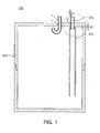
- a water storage tank 100 may include a tank body 200, a first outlet pipe 300, and a second outlet pipe 400.
- the tank body 200 may include an inlet I and an outlet O.
- An inlet pipe P may be provided in the inlet I of the tank body 200 as shown therein. Water can flow into the tank body 200 through the inlet pipe P.
- the inlet pipe P may have a "J" shape. In the case in which the inlet pipe P has a "J" shape, water flowing in through the inlet pipe P may not immediately mix with water 'W' already existing in the tank body 200. This may ensure less variation in the temperature of water 'W' existing in the tank body 200. Accordingly, the temperature control upon water 'W' existing in the tank body 200 may be facilitated.
- a first outlet pipe 300 may be provided in the outlet O of the tank body 200, as will be described below.
- a second outlet pipe 400 is connected to the first outlet pipe 300, thereby discharging water 'W', stored in the tank body 200, to the outside.
- the first outlet pipe 300 may be provided in the outlet O of the tank body 200.
- One side of the first outlet pipe 300 may be placed outside the tank body 200 as in the illustrated embodiment.
- the other side of the first outlet pipe 300 may be placed inside the tank body 200.
- the other side of the first outlet pipe 300 may be placed in the upper part of the tank body 200.
- one side of the second outlet pipe 400 may be connected to the other side of the first outlet pipe 300.
- water 'W' or air 'A' existing in the water tank 200 may be discharged to the outside of the tank body 200 through the second outlet pipe 400 and the first outlet pipe 300.
- the other side of the first outlet pipe 300 may be inserted into the one side of the second outlet pipe 400 to thereby create a first gap G1 with respect to the second outlet pipe 400.
- the one side of the second outlet pipe 400 may create a second gap G2 with respect to the tank body 200.
- These first gap G1 and second gap G2 may form a path through which the air 'A' flows out (i.e., an air discharge path).
- first outlet pipe 300 and the second outlet pipe 400 may be subjected to spot-welding to thereby be connected together.
- a welded portion B may be formed in such a location as in the embodiment shown in FIG. 2A and 2B by the spot welding, and accordingly, the first outlet pipe 300 and the second outlet pipe 400 are connected to each other so as to form an air discharge path.
- the method for connecting the first and second outlet pipes 300 and 400 is not limited to the spot-welding, but any method may be used provided that it forms a connection structure that allows for the discharge of air 'A'or water 'W' from the tank body 200 and forms a discharge path for the air 'A' in such a way that the other side of the first outlet pipe 300 is inserted into one side of the second outlet pipe 400 to thereby form a first gap G1 with respect to the second outlet pipe 400 and the one side of the second outlet pipe 400 forms a second gap G2 with respect to the tank body 200.
- the structure as described above allows air 'A' in the tank body 200 to be introduced into the other side of the second outlet pipe 400, namely, the lower end of the second outlet pipe 400 and then be discharged through the first outlet pipe 300.
- air 'A' in the tank body 200 may be introduced into the other side of the first outlet pipe 300, namely, the lower end of the first outlet pipe 300, through the second gap G2 and the first gap G1 and then be discharged to the outside.
- water 'W' is discharged to the outside through the second outlet pipe 400 and the first outlet pipe 300 by the water inflow pressure
- water 'W' is prevented from being introduced directly into the first outlet pipe 300 through the second gap G2 and the first gap G1 and being discharged to the outside. That is, since the other side of the first outlet pipe 300 is placed in the upper part of the tank body 200 as described above, water 'W' placed in the upper part of the tank body 200 is prevented from being introduced into and discharged through the first outlet pipe 300 via the second gap G2 and the first gap G1. Consequently, water 'W' in the upper part of the tank body 200 does not mix with water being discharged to the outside through the second outlet pipe 400 and the first outlet pipe 300 by water inflow pressure.
- the internal pressure of the tank body 200 is greater than the external pressure thereof due to the water inflow pressure. For this reason, water 'W', having been discharged to the outside through the second outlet pipe 400 and the first outlet pipe 300 by the water inflow pressure, does not flow back into the tank body 200 through the first gap G1 and the second gap G2.
- the other side of the second outlet pipe 400 may be placed in the lower part of the tank body 200. Accordingly, when water 'W' in the tank body 200 is discharged to the outside through the second outlet pipe 400 and the first outlet pipe 300 by the water inflow pressure as shown in FIG. 6 , a portion of water 'W' placed in the lower part of the tank body 200 may thus be discharged first to the outside. Also, as described above, a portion of water 'W' placed in the upper part of the tank body 200 is not introduced into the first outlet pipe 300 through the second gap G2 and the first gap G1 and thus not discharged to the outside. Thus, a portion of water 'W' placed in the lower part of the tank body 200 may be discharged out of the tank body 200 through the second outlet pipe 400 and the first outlet pipe 300, without mixing with water existing in the upper part of the tank body 200.
- the water storage tank 100 is exemplified as a cold water storage tank including an evaporator E in the tank body 200.
- water 'W' having flowed into the tank body 200 is stored in the tank body 200 and thereby increases a water level within the tank body 200.
- a freezing system (not shown) is driven to circulate a cold refrigerant within the evaporator E, water 'W' stored in the tank body 200 is cooled down and becomes cold water.
- a portion of water 'W' placed in the lower part of the tank body 200 and having a relatively low temperature is discharged first to the outside of the tank body 200 without mixing with a portion of water 'W' placed in the upper part of the tank body 200 and having a relatively high temperature.
- the internal pressure of the tank body 200 is higher than the external pressure of the tank body 200 due to the water inflow pressure. For this reason, a portion of water 'W', placed in the lower part of the tank body 200 at a relatively low temperature and discharged out of the tank body 200 through the second outlet pipe 400 and the first outlet pipe 300, does not flow back to the tank body through the first gap G1 and the second gap G2.
- the use of the water storage tank 100 according to the exemplary embodiments of the present invention may facilitate the flow of water into the water storage tank, and allow water to be discharged by water inflow pressure. Furthermore, when water stored in the water storage tank is discharged to the outside by water inflow pressure, water is prevented from being discharged through an air discharge path, and thus the undesired mixing of water from an air discharge path with water from an outlet pipe can be obviated.
- water having a temperature desired by a user may be provided.
- the flow of water into a water storage tank can be facilitated.
- water can be discharged by water inflow pressure.
- water having a temperature desired by a user can be provided.
Landscapes
- Engineering & Computer Science (AREA)
- Structural Engineering (AREA)
- Health & Medical Sciences (AREA)
- Life Sciences & Earth Sciences (AREA)
- Hydrology & Water Resources (AREA)
- Public Health (AREA)
- Water Supply & Treatment (AREA)
- Devices For Dispensing Beverages (AREA)
- Air Humidification (AREA)
- Details Of Rigid Or Semi-Rigid Containers (AREA)
Description
- The present invention relates to a water storage tank according to the preamble of claim 1 capable of preventing water from flowing out through an air discharge path, which is configured to facilitate the inflow of water.
- In general, a water storage tank is a device that stores and discharges water therein to the outside. The water storage tank may be provided with a heater or an evaporator, which is used in a freezing system. A water storage tank including a heater may be used as a warm water storage tank, while a water storage tank including an evaporator may be used as a cold water storage tank.
- Such a water storage tank may have an inlet and an outlet. The inlet and the outlet are provided with an inlet pipe and an outlet pipe, respectively. Thus, water is introduced into a water storage tank through the inlet pipe, and water, stored in the water storage tank, is discharged to the outside through the outlet pipe.
- In order to facilitate water flow into a water storage tank, an air discharge path, such as an air hole, is provided in the upper part of an outlet pipe placed inside the water storage tank. Through this air discharge path, air existing in the water storage tank can be discharged to the outside when water is flowing in through an inlet pipe.
- Meanwhile, when a water storage tank is used at a place in which water flows in at high pressure, such as in direct type water purifiers, water stored in the water storage tank is discharged to the outside by the pressure at which water is flowing into the water storage tank (hereinafter, also referred to as water inflow pressure). Here, the direct type water purifiers refer to those that directly supply water to a purifying filter using water pressure without a pump.
- However, in the case in which a water level in a water storage tank is higher than an air discharge path such as an air hole, water is undesirably discharged through the air discharge path and mixed with water being discharged through an outlet pipe by the water inflow pressure.
- In this case, if the water storage tank is a cold water storage tank, water placed in the lower part of the water storage tank in which temperature is relatively low, may be discharged, mixed with water placed in the upper part of the water storage tank in which temperature is relatively high.
- Consequently, water having a desired temperature may not be supplied to a user.
- A prior art water storage tank is known from patent application
US2005/062283A1 , which discloses a tank comprising a first and a second tank-fittings, each tank-fitting interconnecting an external pipe to a tee fitting, such as a sanitary-tee fitting, said external pipes being respectively inlet and outlet pipes for the tank. Another prior art tank is also known fromDE9108770U1 . - The present invention is made to address at least one of requirements or limitations of the related-art water storage tank as described above.
- An aspect of the present invention is to facilitate water flow into a water storage tank.
- Another aspect of the present invention is to discharge water by water inflow pressure.
- Another aspect of the present invention is to prevent water from flowing out through an air discharge path at the time of discharging water stored in a water storage tank by water inflow pressure, so that water discharged through an outlet pipe does not mix with water undesirably discharged through the air discharge path.
- Another aspect of the present invention is to supply water having a temperature desired by a user.
- The present invention is basically associated with using two interconnected outlet pipes and forming an air discharge path between the two outlet pipes.
- According to an aspect of the present invention, there is provided a water storage tank including: a tank body including an inlet and an outlet; a first outlet pipe provided in the outlet of the tank body such that one side of the first outlet pipe is placed outside the tank body while the other side thereof is placed inside the tank body; and a second outlet pipe having one side connected to the other side of the first outlet pipe such that air or water existing in the tank body is discharged to the outside.
- The other side of the first outlet pipe is inserted into the one side of the second outlet pipe to form a first gap with respect to the second outlet pipe, and the one side of the second outlet pipe forms a second gap with respect to the tank body, thereby forming an air discharge path.
- The other side of the first outlet pipe may be placed in the upper part of the tank body, and the other side of the second outlet pipe may be placed in the lower part of the tank body.
- The first outlet pipe and the second outlet pipe may be connected together by spot-welding.
- The water storage tank may further include an evaporator placed inside or outside the tank body and cooling water received in the tank body.
- The water storage tank may further include an inlet pipe placed in the inlet and having a J-shape.
- The above and other aspects, features and other advantages of the present invention will be more clearly understood from the following detailed description taken in conjunction with the accompanying drawings, in which:
-
FIG. 1 is a cross-sectional view illustrating a water storage tank according to an exemplary embodiment of the present invention; -
FIG. 2A is an enlarged cross-sectional view illustrating a water discharge structure of a water storage tank according to an exemplary embodiment of the present invention; -
FIG. 2B is a cross-sectional view taken along line A-A' ofFIG. 2A ; and -
FIGS. 3 through 6 are cross-sectional views illustrating the operation of a water storage tank being used as a cold water storage tank, according to an exemplary embodiment of the present invention. - Exemplary embodiments of the present invention will now be described in detail with reference to the accompanying drawings.
- The invention may, however, be embodied in many different forms and should not be construed as being limited to the embodiments set forth herein. Rather, these embodiments are provided so that this disclosure will be thorough and complete, and will fully convey the scope of the invention to those skilled in the art. In the drawings, like reference numerals refer to like elements throughout.
- Exemplary embodiments of the present invention are basically associated with using two interconnected outlet pipes and having an air discharge path formed between the two outlet pipes.
- As in an exemplary embodiment depicted in
FIG. 1 , awater storage tank 100 may include atank body 200, afirst outlet pipe 300, and asecond outlet pipe 400. - As in the exemplary embodiment depicted in
FIG. 1 , thetank body 200 may include an inlet I and an outlet O. An inlet pipe P may be provided in the inlet I of thetank body 200 as shown therein. Water can flow into thetank body 200 through the inlet pipe P. As shown therein, the inlet pipe P may have a "J" shape. In the case in which the inlet pipe P has a "J" shape, water flowing in through the inlet pipe P may not immediately mix with water 'W' already existing in thetank body 200. This may ensure less variation in the temperature of water 'W' existing in thetank body 200. Accordingly, the temperature control upon water 'W' existing in thetank body 200 may be facilitated. Furthermore, afirst outlet pipe 300 may be provided in the outlet O of thetank body 200, as will be described below. Asecond outlet pipe 400 is connected to thefirst outlet pipe 300, thereby discharging water 'W', stored in thetank body 200, to the outside. - As in an embodiment depicted in
FIGS. 1 and2 , thefirst outlet pipe 300 may be provided in the outlet O of thetank body 200. One side of thefirst outlet pipe 300 may be placed outside thetank body 200 as in the illustrated embodiment. Furthermore, the other side of thefirst outlet pipe 300 may be placed inside thetank body 200. The other side of thefirst outlet pipe 300 may be placed in the upper part of thetank body 200. - As in the embodiment depicted in
FIGS. 1 and2 , one side of thesecond outlet pipe 400 may be connected to the other side of thefirst outlet pipe 300. Thus, water 'W' or air 'A' existing in thewater tank 200 may be discharged to the outside of thetank body 200 through thesecond outlet pipe 400 and thefirst outlet pipe 300. - As in the embodiment depicted in
FIGS. 1 and2 , the other side of thefirst outlet pipe 300 may be inserted into the one side of thesecond outlet pipe 400 to thereby create a first gap G1 with respect to thesecond outlet pipe 400. Furthermore, the one side of thesecond outlet pipe 400 may create a second gap G2 with respect to thetank body 200. These first gap G1 and second gap G2 may form a path through which the air 'A' flows out (i.e., an air discharge path). - To this end, the
first outlet pipe 300 and thesecond outlet pipe 400 may be subjected to spot-welding to thereby be connected together. For example, a welded portion B may be formed in such a location as in the embodiment shown inFIG. 2A and 2B by the spot welding, and accordingly, thefirst outlet pipe 300 and thesecond outlet pipe 400 are connected to each other so as to form an air discharge path. However, the method for connecting the first andsecond outlet pipes tank body 200 and forms a discharge path for the air 'A' in such a way that the other side of thefirst outlet pipe 300 is inserted into one side of thesecond outlet pipe 400 to thereby form a first gap G1 with respect to thesecond outlet pipe 400 and the one side of thesecond outlet pipe 400 forms a second gap G2 with respect to thetank body 200. - Accordingly, as shown in
FIG. 3 , when water flows in through the inlet pipe P provided in the inlet I of thetank body 200, the structure as described above allows air 'A' in thetank body 200 to be introduced into the other side of thesecond outlet pipe 400, namely, the lower end of thesecond outlet pipe 400 and then be discharged through thefirst outlet pipe 300. Furthermore, as shown in the drawing, air 'A' in thetank body 200 may be introduced into the other side of thefirst outlet pipe 300, namely, the lower end of thefirst outlet pipe 300, through the second gap G2 and the first gap G1 and then be discharged to the outside. - In the case in which water continues to flow into the tank body and reaches a point at which a level of water 'W' stored in the
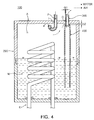
water storage tank 100 exceeds the end portion of the other side of thesecond outlet pipe 400, namely, the lower end thereof as shown inFIG. 4 , air 'A' in thetank body 200 is introduced into thefirst outlet pipe 300 only through the second gap G2 and the first gap G1, thereby being discharged to the outside. This facilitates the flow of water into thetank body 200. - Thereafter, in the case in which water flows further into the
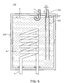
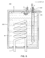
tank body 200 and thus reaches a point at which a level of water 'W' stored in thetank body 200 exceeds the end portion of the other side of thefirst outlet pipe 300, namely, the lower end thereof as shown inFIG. 5 , the first gap G1 is blocked by the water 'W' in thetank body 200. In this case, air 'A' in thetank body 200 can no longer be discharged to the outside even though water is introduced into thetank body 200. Therefore, when water flows into thetank body 200 through the inlet pipe P in the above-mentioned state, water 'W' stored in thetank body 200 is discharged to the outside through thesecond outlet pipe 400 and thefirst outlet pipe 300 by water inflow pressure as shown inFIG. 6 . At this time, a level of water W stored in thetank body 200 no longer increases, nor exceeds the water level shown inFIGS. 5 and6 . - Accordingly, while water 'W' is discharged to the outside through the
second outlet pipe 400 and thefirst outlet pipe 300 by the water inflow pressure, water 'W' is prevented from being introduced directly into thefirst outlet pipe 300 through the second gap G2 and the first gap G1 and being discharged to the outside. That is, since the other side of thefirst outlet pipe 300 is placed in the upper part of thetank body 200 as described above, water 'W' placed in the upper part of thetank body 200 is prevented from being introduced into and discharged through thefirst outlet pipe 300 via the second gap G2 and the first gap G1. Consequently, water 'W' in the upper part of thetank body 200 does not mix with water being discharged to the outside through thesecond outlet pipe 400 and thefirst outlet pipe 300 by water inflow pressure. - Furthermore, the internal pressure of the
tank body 200 is greater than the external pressure thereof due to the water inflow pressure. For this reason, water 'W', having been discharged to the outside through thesecond outlet pipe 400 and thefirst outlet pipe 300 by the water inflow pressure, does not flow back into thetank body 200 through the first gap G1 and the second gap G2. - Meanwhile, as in the embodiment depicted in
FIGS. 1 and2 , the other side of thesecond outlet pipe 400 may be placed in the lower part of thetank body 200. Accordingly, when water 'W' in thetank body 200 is discharged to the outside through thesecond outlet pipe 400 and thefirst outlet pipe 300 by the water inflow pressure as shown inFIG. 6 , a portion of water 'W' placed in the lower part of thetank body 200 may thus be discharged first to the outside. Also, as described above, a portion of water 'W' placed in the upper part of thetank body 200 is not introduced into thefirst outlet pipe 300 through the second gap G2 and the first gap G1 and thus not discharged to the outside. Thus, a portion of water 'W' placed in the lower part of thetank body 200 may be discharged out of thetank body 200 through thesecond outlet pipe 400 and thefirst outlet pipe 300, without mixing with water existing in the upper part of thetank body 200. - Hereinafter, the operation of the
water storage tank 100, according to an exemplary embodiment of the present invention, will be described in detail with reference toFIGS. 3 through 6 . In this embodiment, thewater storage tank 100 is exemplified as a cold water storage tank including an evaporator E in thetank body 200. - First, as shown in
FIG. 3 , when water 'W' flows into thetank body 200 through the inlet pipe P provided at thewater storage tank 100, air 'A' existing in thetank body 200 is introduced into thefirst outlet pipe 300 via thesecond outlet pipe 400 or via the second gap G2 and the first gap G1, and then discharged to the outside. Accordingly, water can be easily flow into thetank body 200. - As shown in the drawing, water 'W' having flowed into the
tank body 200 is stored in thetank body 200 and thereby increases a water level within thetank body 200. In addition, if a freezing system (not shown) is driven to circulate a cold refrigerant within the evaporator E, water 'W' stored in thetank body 200 is cooled down and becomes cold water. - As shown in
FIG. 4 , as the flow of water into thetank body 200 proceeds and a water level within thetank body 200 exceeds the end portion of the other side of thesecond outlet pipe 400, namely, the lower end thereof, air 'A' existing in thetank body 200 is discharged out of thetank body 200 only through the second gap G2 and the first gap G1. - Subsequently, as shown in
FIG. 5 , as water flows further into thetank body 200 and reaches the end portion of the other side of thefirst outlet pipe 300, namely, the lower end thereof, water 'W' stored in thetank body 200 blocks the end portion of the other side of thefirst outlet pipe 300. Even if more water flows into thetank body 200 thereafter, air 'A' in thetank body 200 is no longer discharged to the outside. - As shown in
FIG. 6 , as the flow of water into thetank body 200 further proceeds in the above state, water 'W' stored in thetank body 200 and cooled by the evaporator E is discharged to the outside of thetank body 200 through thesecond outlet pipe 400 and thefirst outlet pipe 300 by water inflow pressure. At this time, a portion of water 'W' placed in the upper part of thetank body 200 and having a relatively high temperature is prevented from being introduced into thefirst outlet pipe 300 since a level of water 'W' stored in thetank body 200 does not ever go beyond the end portion of the one side of thesecond outlet pipe 400, namely, the upper end thereof. Therefore, a portion of water 'W' placed in the lower part of thetank body 200 and having a relatively low temperature is discharged first to the outside of thetank body 200 without mixing with a portion of water 'W' placed in the upper part of thetank body 200 and having a relatively high temperature. - Furthermore, the internal pressure of the
tank body 200 is higher than the external pressure of thetank body 200 due to the water inflow pressure. For this reason, a portion of water 'W', placed in the lower part of thetank body 200 at a relatively low temperature and discharged out of thetank body 200 through thesecond outlet pipe 400 and thefirst outlet pipe 300, does not flow back to the tank body through the first gap G1 and the second gap G2. - In the above manner, water 'W' having a temperature desired by a user can be supplied.
- The use of the
water storage tank 100 according to the exemplary embodiments of the present invention may facilitate the flow of water into the water storage tank, and allow water to be discharged by water inflow pressure. Furthermore, when water stored in the water storage tank is discharged to the outside by water inflow pressure, water is prevented from being discharged through an air discharge path, and thus the undesired mixing of water from an air discharge path with water from an outlet pipe can be obviated. - Accordingly, water having a temperature desired by a user may be provided.
- As set forth above, according to exemplary embodiments of the invention, the flow of water into a water storage tank can be facilitated.
- According to exemplary embodiments of the invention, water can be discharged by water inflow pressure.
- Furthermore, according to exemplary embodiments of the invention, when water stored in the water storage tank is discharged to the outside by water inflow pressure, water is prevented from being discharged through an air discharge path, thereby preventing water from an outlet pipe from mixing with water from the air discharge path.
- In addition, according to exemplary embodiments of the invention, water having a temperature desired by a user can be provided.
Claims (5)
- A water storage tank (100) comprising:a tank body (200) including an inlet (I) and an outlet (O);a first outlet pipe (300) provided in the outlet (O) of the tank body (200) such that one side of the first outlet pipe (300) is placed outside the tank body (200) while the other side thereof is placed inside the tank body (200); anda second outlet pipe (400) having one side connected to the other side of the first outlet pipe (300) such that air or water existing in the tank body (200) is in use discharged to the outside;characterized in that the other side of the first outlet pipe (300) is inserted into the one side of the second outlet pipe (400) to form a first gap (G1) with respect to the second outlet pipe (400), and the one side of the second outlet pipe (400) forms a second gap (G2) with respect to the tank body (200), thereby forming an air discharge path.
- The water storage tank (200) of claim 1, wherein the other side of the first outlet pipe (300) is placed in the upper part of the tank body (200), and the other side of the second outlet pipe (400) is placed in the lower part of the tank body (200).
- The water storage tank (200) of claim 1, wherein the first outlet pipe (300) and the second outlet pipe (400) are connected by spot-welding.
- The water storage tank (200) of claim 1, further comprising an evaporator (E) placed inside or outside the tank body (200) and cooling water received in the tank body (200).
- The water storage tank (200) of claim 1, further comprising an inlet pipe (P) placed in the inlet (I) and having a "J"-shape.
Applications Claiming Priority (1)
| Application Number | Priority Date | Filing Date | Title |
|---|---|---|---|
| KR1020100079670A KR101744554B1 (en) | 2010-08-18 | 2010-08-18 | Water storage tank |
Publications (3)
| Publication Number | Publication Date |
|---|---|
| EP2420627A2 EP2420627A2 (en) | 2012-02-22 |
| EP2420627A3 EP2420627A3 (en) | 2013-06-26 |
| EP2420627B1 true EP2420627B1 (en) | 2015-11-11 |
Family
ID=44799456
Family Applications (1)
| Application Number | Title | Priority Date | Filing Date |
|---|---|---|---|
| EP10181330.1A Active EP2420627B1 (en) | 2010-08-18 | 2010-09-28 | Water storage tank |
Country Status (2)
| Country | Link |
|---|---|
| EP (1) | EP2420627B1 (en) |
| KR (1) | KR101744554B1 (en) |
Families Citing this family (3)
| Publication number | Priority date | Publication date | Assignee | Title |
|---|---|---|---|---|
| KR101439831B1 (en) * | 2012-10-30 | 2014-09-15 | 코웨이 주식회사 | Cold water tank |
| CN104929193A (en) * | 2015-07-19 | 2015-09-23 | 张若玮 | Domestic water storage device |
| CN105297834A (en) * | 2015-10-21 | 2016-02-03 | 无锡惠山泵业有限公司 | Water tank |
Family Cites Families (7)
| Publication number | Priority date | Publication date | Assignee | Title |
|---|---|---|---|---|
| GB704165A (en) * | 1951-03-17 | 1954-02-17 | Range Boilers Ltd | Improvements in or relating to domestic hot water systems |
| US3470897A (en) * | 1966-12-02 | 1969-10-07 | Cory Corp | Liquid heater |
| IT1144132B (en) * | 1981-03-03 | 1986-10-29 | Indesit | REFRIGERATED CABINET WORKING ALSO AS WATER HEATER |
| US4700734A (en) * | 1985-07-22 | 1987-10-20 | Mccauley Robert G | Water collecting and spring box and gauging system and holding tank |
| DE9108770U1 (en) * | 1991-07-17 | 1992-08-13 | Steinmetz, Günter, 8047 Karlsfeld | Automatic water inlet valve for liquid collection tank |
| US7121589B2 (en) * | 2003-09-24 | 2006-10-17 | Norwesco, Inc. | Tank fitting and method of use |
| US7234484B2 (en) * | 2004-09-03 | 2007-06-26 | Ruth Laws | Pressure tank apparatus and method |
-
2010
- 2010-08-18 KR KR1020100079670A patent/KR101744554B1/en active IP Right Grant
- 2010-09-28 EP EP10181330.1A patent/EP2420627B1/en active Active
Also Published As
| Publication number | Publication date |
|---|---|
| KR101744554B1 (en) | 2017-06-12 |
| EP2420627A2 (en) | 2012-02-22 |
| EP2420627A3 (en) | 2013-06-26 |
| KR20120017153A (en) | 2012-02-28 |
Similar Documents
| Publication | Publication Date | Title |
|---|---|---|
| EP2833072B1 (en) | Heating and hot water supply system | |
| CN107003057B (en) | Cold water generation tank and water cooler equipped with same | |
| EP3239618B1 (en) | Water heater system | |
| JP2006349229A (en) | Refrigerant flow divider | |
| EP2420627B1 (en) | Water storage tank | |
| CN109906313A (en) | System for storing aqueous solutions on board a vehicle | |
| CN110836276A (en) | Tap water outlet mechanism | |
| CN104114963B (en) | Aircondition | |
| EP2204506B1 (en) | Cold water tank and water treatment apparatus having the same | |
| CN211259720U (en) | Faucet valve core seat | |
| CN211288843U (en) | Tap water outlet mechanism | |
| CN110822123A (en) | Faucet valve core seat | |
| CN110873203A (en) | Valve core seat | |
| CN110748673A (en) | Water outlet mechanism | |
| KR101642344B1 (en) | Improve the cooling efficiency of the cooling system is equipped with a water cooler | |
| US20190022604A1 (en) | Washer liquid supply system | |
| US10647303B2 (en) | Washer liquid supply system | |
| US10352587B2 (en) | Water heater distribution tube | |
| CN215559049U (en) | Water purifying equipment | |
| CN110537839B (en) | Control method of soda water machine, soda water machine and computer readable storage medium | |
| CN109665480B (en) | Water treatment device | |
| JP2014018461A (en) | Bathtub adapter and hot water supply using the same | |
| JP2006170516A (en) | Air conditioner | |
| JP2021032105A (en) | Foreign matter discharge device | |
| CN214406680U (en) | Electronic ice liner and water purifying equipment |
Legal Events
| Date | Code | Title | Description |
|---|---|---|---|
| AK | Designated contracting states |
Kind code of ref document: A2 Designated state(s): AL AT BE BG CH CY CZ DE DK EE ES FI FR GB GR HR HU IE IS IT LI LT LU LV MC MK MT NL NO PL PT RO SE SI SK SM TR |
|
| AX | Request for extension of the european patent |
Extension state: BA ME RS |
|
| PUAI | Public reference made under article 153(3) epc to a published international application that has entered the european phase |
Free format text: ORIGINAL CODE: 0009012 |
|
| PUAL | Search report despatched |
Free format text: ORIGINAL CODE: 0009013 |
|
| AK | Designated contracting states |
Kind code of ref document: A3 Designated state(s): AL AT BE BG CH CY CZ DE DK EE ES FI FR GB GR HR HU IE IS IT LI LT LU LV MC MK MT NL NO PL PT RO SE SI SK SM TR |
|
| AX | Request for extension of the european patent |
Extension state: BA ME RS |
|
| RIC1 | Information provided on ipc code assigned before grant |
Ipc: E03B 11/02 20060101AFI20130521BHEP Ipc: E03B 11/04 20060101ALI20130521BHEP |
|
| 17P | Request for examination filed |
Effective date: 20131216 |
|
| RBV | Designated contracting states (corrected) |
Designated state(s): AL AT BE BG CH CY CZ DE DK EE ES FI FR GB GR HR HU IE IS IT LI LT LU LV MC MK MT NL NO PL PT RO SE SI SK SM TR |
|
| RIC1 | Information provided on ipc code assigned before grant |
Ipc: E03B 11/04 20060101ALI20150327BHEP Ipc: E03B 11/02 20060101AFI20150327BHEP |
|
| GRAP | Despatch of communication of intention to grant a patent |
Free format text: ORIGINAL CODE: EPIDOSNIGR1 |
|
| INTG | Intention to grant announced |
Effective date: 20150508 |
|
| GRAS | Grant fee paid |
Free format text: ORIGINAL CODE: EPIDOSNIGR3 |
|
| GRAA | (expected) grant |
Free format text: ORIGINAL CODE: 0009210 |
|
| AK | Designated contracting states |
Kind code of ref document: B1 Designated state(s): AL AT BE BG CH CY CZ DE DK EE ES FI FR GB GR HR HU IE IS IT LI LT LU LV MC MK MT NL NO PL PT RO SE SI SK SM TR |
|
| REG | Reference to a national code |
Ref country code: GB Ref legal event code: FG4D |
|
| REG | Reference to a national code |
Ref country code: CH Ref legal event code: EP |
|
| REG | Reference to a national code |
Ref country code: IE Ref legal event code: FG4D |
|
| REG | Reference to a national code |
Ref country code: AT Ref legal event code: REF Ref document number: 760539 Country of ref document: AT Kind code of ref document: T Effective date: 20151215 |
|
| REG | Reference to a national code |
Ref country code: DE Ref legal event code: R096 Ref document number: 602010028926 Country of ref document: DE |
|
| REG | Reference to a national code |
Ref country code: LT Ref legal event code: MG4D |
|
| REG | Reference to a national code |
Ref country code: NL Ref legal event code: MP Effective date: 20160211 |
|
| REG | Reference to a national code |
Ref country code: AT Ref legal event code: MK05 Ref document number: 760539 Country of ref document: AT Kind code of ref document: T Effective date: 20151111 |
|
| PG25 | Lapsed in a contracting state [announced via postgrant information from national office to epo] |
Ref country code: IS Free format text: LAPSE BECAUSE OF FAILURE TO SUBMIT A TRANSLATION OF THE DESCRIPTION OR TO PAY THE FEE WITHIN THE PRESCRIBED TIME-LIMIT Effective date: 20160311 Ref country code: NL Free format text: LAPSE BECAUSE OF FAILURE TO SUBMIT A TRANSLATION OF THE DESCRIPTION OR TO PAY THE FEE WITHIN THE PRESCRIBED TIME-LIMIT Effective date: 20151111 Ref country code: LT Free format text: LAPSE BECAUSE OF FAILURE TO SUBMIT A TRANSLATION OF THE DESCRIPTION OR TO PAY THE FEE WITHIN THE PRESCRIBED TIME-LIMIT Effective date: 20151111 Ref country code: NO Free format text: LAPSE BECAUSE OF FAILURE TO SUBMIT A TRANSLATION OF THE DESCRIPTION OR TO PAY THE FEE WITHIN THE PRESCRIBED TIME-LIMIT Effective date: 20160211 Ref country code: HR Free format text: LAPSE BECAUSE OF FAILURE TO SUBMIT A TRANSLATION OF THE DESCRIPTION OR TO PAY THE FEE WITHIN THE PRESCRIBED TIME-LIMIT Effective date: 20151111 Ref country code: ES Free format text: LAPSE BECAUSE OF FAILURE TO SUBMIT A TRANSLATION OF THE DESCRIPTION OR TO PAY THE FEE WITHIN THE PRESCRIBED TIME-LIMIT Effective date: 20151111 |
|
| PG25 | Lapsed in a contracting state [announced via postgrant information from national office to epo] |
Ref country code: FI Free format text: LAPSE BECAUSE OF FAILURE TO SUBMIT A TRANSLATION OF THE DESCRIPTION OR TO PAY THE FEE WITHIN THE PRESCRIBED TIME-LIMIT Effective date: 20151111 Ref country code: LV Free format text: LAPSE BECAUSE OF FAILURE TO SUBMIT A TRANSLATION OF THE DESCRIPTION OR TO PAY THE FEE WITHIN THE PRESCRIBED TIME-LIMIT Effective date: 20151111 Ref country code: SE Free format text: LAPSE BECAUSE OF FAILURE TO SUBMIT A TRANSLATION OF THE DESCRIPTION OR TO PAY THE FEE WITHIN THE PRESCRIBED TIME-LIMIT Effective date: 20151111 Ref country code: PL Free format text: LAPSE BECAUSE OF FAILURE TO SUBMIT A TRANSLATION OF THE DESCRIPTION OR TO PAY THE FEE WITHIN THE PRESCRIBED TIME-LIMIT Effective date: 20151111 Ref country code: AT Free format text: LAPSE BECAUSE OF FAILURE TO SUBMIT A TRANSLATION OF THE DESCRIPTION OR TO PAY THE FEE WITHIN THE PRESCRIBED TIME-LIMIT Effective date: 20151111 Ref country code: GR Free format text: LAPSE BECAUSE OF FAILURE TO SUBMIT A TRANSLATION OF THE DESCRIPTION OR TO PAY THE FEE WITHIN THE PRESCRIBED TIME-LIMIT Effective date: 20160212 Ref country code: PT Free format text: LAPSE BECAUSE OF FAILURE TO SUBMIT A TRANSLATION OF THE DESCRIPTION OR TO PAY THE FEE WITHIN THE PRESCRIBED TIME-LIMIT Effective date: 20160311 |
|
| PG25 | Lapsed in a contracting state [announced via postgrant information from national office to epo] |
Ref country code: CZ Free format text: LAPSE BECAUSE OF FAILURE TO SUBMIT A TRANSLATION OF THE DESCRIPTION OR TO PAY THE FEE WITHIN THE PRESCRIBED TIME-LIMIT Effective date: 20151111 |
|
| REG | Reference to a national code |
Ref country code: DE Ref legal event code: R097 Ref document number: 602010028926 Country of ref document: DE |
|
| PG25 | Lapsed in a contracting state [announced via postgrant information from national office to epo] |
Ref country code: RO Free format text: LAPSE BECAUSE OF FAILURE TO SUBMIT A TRANSLATION OF THE DESCRIPTION OR TO PAY THE FEE WITHIN THE PRESCRIBED TIME-LIMIT Effective date: 20151111 Ref country code: SM Free format text: LAPSE BECAUSE OF FAILURE TO SUBMIT A TRANSLATION OF THE DESCRIPTION OR TO PAY THE FEE WITHIN THE PRESCRIBED TIME-LIMIT Effective date: 20151111 Ref country code: DK Free format text: LAPSE BECAUSE OF FAILURE TO SUBMIT A TRANSLATION OF THE DESCRIPTION OR TO PAY THE FEE WITHIN THE PRESCRIBED TIME-LIMIT Effective date: 20151111 Ref country code: SK Free format text: LAPSE BECAUSE OF FAILURE TO SUBMIT A TRANSLATION OF THE DESCRIPTION OR TO PAY THE FEE WITHIN THE PRESCRIBED TIME-LIMIT Effective date: 20151111 Ref country code: EE Free format text: LAPSE BECAUSE OF FAILURE TO SUBMIT A TRANSLATION OF THE DESCRIPTION OR TO PAY THE FEE WITHIN THE PRESCRIBED TIME-LIMIT Effective date: 20151111 |
|
| PLBE | No opposition filed within time limit |
Free format text: ORIGINAL CODE: 0009261 |
|
| STAA | Information on the status of an ep patent application or granted ep patent |
Free format text: STATUS: NO OPPOSITION FILED WITHIN TIME LIMIT |
|
| 26N | No opposition filed |
Effective date: 20160812 |
|
| PG25 | Lapsed in a contracting state [announced via postgrant information from national office to epo] |
Ref country code: SI Free format text: LAPSE BECAUSE OF FAILURE TO SUBMIT A TRANSLATION OF THE DESCRIPTION OR TO PAY THE FEE WITHIN THE PRESCRIBED TIME-LIMIT Effective date: 20151111 |
|
| PG25 | Lapsed in a contracting state [announced via postgrant information from national office to epo] |
Ref country code: BE Free format text: LAPSE BECAUSE OF FAILURE TO SUBMIT A TRANSLATION OF THE DESCRIPTION OR TO PAY THE FEE WITHIN THE PRESCRIBED TIME-LIMIT Effective date: 20151111 |
|
| REG | Reference to a national code |
Ref country code: DE Ref legal event code: R119 Ref document number: 602010028926 Country of ref document: DE |
|
| PG25 | Lapsed in a contracting state [announced via postgrant information from national office to epo] |
Ref country code: MC Free format text: LAPSE BECAUSE OF FAILURE TO SUBMIT A TRANSLATION OF THE DESCRIPTION OR TO PAY THE FEE WITHIN THE PRESCRIBED TIME-LIMIT Effective date: 20151111 |
|
| REG | Reference to a national code |
Ref country code: CH Ref legal event code: PL |
|
| GBPC | Gb: european patent ceased through non-payment of renewal fee |
Effective date: 20160928 |
|
| REG | Reference to a national code |
Ref country code: IE Ref legal event code: MM4A |
|
| REG | Reference to a national code |
Ref country code: FR Ref legal event code: ST Effective date: 20170531 |
|
| PG25 | Lapsed in a contracting state [announced via postgrant information from national office to epo] |
Ref country code: IE Free format text: LAPSE BECAUSE OF NON-PAYMENT OF DUE FEES Effective date: 20160928 Ref country code: FR Free format text: LAPSE BECAUSE OF NON-PAYMENT OF DUE FEES Effective date: 20160930 Ref country code: GB Free format text: LAPSE BECAUSE OF NON-PAYMENT OF DUE FEES Effective date: 20160928 Ref country code: LI Free format text: LAPSE BECAUSE OF NON-PAYMENT OF DUE FEES Effective date: 20160930 Ref country code: CH Free format text: LAPSE BECAUSE OF NON-PAYMENT OF DUE FEES Effective date: 20160930 Ref country code: DE Free format text: LAPSE BECAUSE OF NON-PAYMENT OF DUE FEES Effective date: 20170401 |
|
| PG25 | Lapsed in a contracting state [announced via postgrant information from national office to epo] |
Ref country code: LU Free format text: LAPSE BECAUSE OF NON-PAYMENT OF DUE FEES Effective date: 20160928 |
|
| PG25 | Lapsed in a contracting state [announced via postgrant information from national office to epo] |
Ref country code: CY Free format text: LAPSE BECAUSE OF FAILURE TO SUBMIT A TRANSLATION OF THE DESCRIPTION OR TO PAY THE FEE WITHIN THE PRESCRIBED TIME-LIMIT Effective date: 20151111 Ref country code: HU Free format text: LAPSE BECAUSE OF FAILURE TO SUBMIT A TRANSLATION OF THE DESCRIPTION OR TO PAY THE FEE WITHIN THE PRESCRIBED TIME-LIMIT; INVALID AB INITIO Effective date: 20100928 |
|
| PG25 | Lapsed in a contracting state [announced via postgrant information from national office to epo] |
Ref country code: TR Free format text: LAPSE BECAUSE OF FAILURE TO SUBMIT A TRANSLATION OF THE DESCRIPTION OR TO PAY THE FEE WITHIN THE PRESCRIBED TIME-LIMIT Effective date: 20151111 Ref country code: MK Free format text: LAPSE BECAUSE OF FAILURE TO SUBMIT A TRANSLATION OF THE DESCRIPTION OR TO PAY THE FEE WITHIN THE PRESCRIBED TIME-LIMIT Effective date: 20151111 Ref country code: MT Free format text: LAPSE BECAUSE OF NON-PAYMENT OF DUE FEES Effective date: 20160930 |
|
| PG25 | Lapsed in a contracting state [announced via postgrant information from national office to epo] |
Ref country code: BG Free format text: LAPSE BECAUSE OF FAILURE TO SUBMIT A TRANSLATION OF THE DESCRIPTION OR TO PAY THE FEE WITHIN THE PRESCRIBED TIME-LIMIT Effective date: 20151111 |
|
| PG25 | Lapsed in a contracting state [announced via postgrant information from national office to epo] |
Ref country code: AL Free format text: LAPSE BECAUSE OF FAILURE TO SUBMIT A TRANSLATION OF THE DESCRIPTION OR TO PAY THE FEE WITHIN THE PRESCRIBED TIME-LIMIT Effective date: 20151111 |
|
| PGFP | Annual fee paid to national office [announced via postgrant information from national office to epo] |
Ref country code: IT Payment date: 20240620 Year of fee payment: 15 |