EP2204202A1 - Spender für medizinische lösung - Google Patents
Spender für medizinische lösung Download PDFInfo
- Publication number
- EP2204202A1 EP2204202A1 EP08838161A EP08838161A EP2204202A1 EP 2204202 A1 EP2204202 A1 EP 2204202A1 EP 08838161 A EP08838161 A EP 08838161A EP 08838161 A EP08838161 A EP 08838161A EP 2204202 A1 EP2204202 A1 EP 2204202A1
- Authority
- EP
- European Patent Office
- Prior art keywords
- medical
- solution
- driving liquid
- administration device
- reservoir
- Prior art date
- Legal status (The legal status is an assumption and is not a legal conclusion. Google has not performed a legal analysis and makes no representation as to the accuracy of the status listed.)
- Withdrawn
Links
- 239000008155 medical solution Substances 0.000 claims abstract description 348
- 239000007788 liquid Substances 0.000 claims abstract description 149
- 239000003550 marker Substances 0.000 claims abstract description 67
- 230000002123 temporal effect Effects 0.000 claims description 30
- 238000001514 detection method Methods 0.000 claims description 26
- 238000005370 electroosmosis Methods 0.000 claims description 22
- 125000006850 spacer group Chemical group 0.000 claims description 10
- 230000000903 blocking effect Effects 0.000 claims description 8
- 238000007599 discharging Methods 0.000 claims description 8
- 239000011324 bead Substances 0.000 claims description 6
- 239000012530 fluid Substances 0.000 claims description 2
- 238000010586 diagram Methods 0.000 description 19
- DDRJAANPRJIHGJ-UHFFFAOYSA-N creatinine Chemical compound CN1CC(=O)NC1=N DDRJAANPRJIHGJ-UHFFFAOYSA-N 0.000 description 4
- 239000002246 antineoplastic agent Substances 0.000 description 3
- 229940041181 antineoplastic drug Drugs 0.000 description 3
- 210000004369 blood Anatomy 0.000 description 3
- 239000008280 blood Substances 0.000 description 3
- 230000003247 decreasing effect Effects 0.000 description 3
- 230000005684 electric field Effects 0.000 description 3
- 238000005086 pumping Methods 0.000 description 3
- 201000009030 Carcinoma Diseases 0.000 description 2
- GHASVSINZRGABV-UHFFFAOYSA-N Fluorouracil Chemical compound FC1=CNC(=O)NC1=O GHASVSINZRGABV-UHFFFAOYSA-N 0.000 description 2
- 102000007066 Prostate-Specific Antigen Human genes 0.000 description 2
- 108010072866 Prostate-Specific Antigen Proteins 0.000 description 2
- 210000004556 brain Anatomy 0.000 description 2
- 239000000470 constituent Substances 0.000 description 2
- 238000012937 correction Methods 0.000 description 2
- 229940109239 creatinine Drugs 0.000 description 2
- 229960002949 fluorouracil Drugs 0.000 description 2
- 239000000576 food coloring agent Substances 0.000 description 2
- 150000002500 ions Chemical class 0.000 description 2
- 230000003204 osmotic effect Effects 0.000 description 2
- 230000004044 response Effects 0.000 description 2
- 210000002966 serum Anatomy 0.000 description 2
- 239000012780 transparent material Substances 0.000 description 2
- 102100036475 Alanine aminotransferase 1 Human genes 0.000 description 1
- 108010082126 Alanine transaminase Proteins 0.000 description 1
- 108010003415 Aspartate Aminotransferases Proteins 0.000 description 1
- 102000004625 Aspartate Aminotransferases Human genes 0.000 description 1
- 102000004190 Enzymes Human genes 0.000 description 1
- 108090000790 Enzymes Proteins 0.000 description 1
- YCKRFDGAMUMZLT-UHFFFAOYSA-N Fluorine atom Chemical compound [F] YCKRFDGAMUMZLT-UHFFFAOYSA-N 0.000 description 1
- 206010062519 Poor quality sleep Diseases 0.000 description 1
- 206010060862 Prostate cancer Diseases 0.000 description 1
- 208000000236 Prostatic Neoplasms Diseases 0.000 description 1
- 239000012503 blood component Substances 0.000 description 1
- 230000036765 blood level Effects 0.000 description 1
- 210000001124 body fluid Anatomy 0.000 description 1
- 230000000747 cardiac effect Effects 0.000 description 1
- 238000002512 chemotherapy Methods 0.000 description 1
- 230000002778 chronopharmacological effect Effects 0.000 description 1
- 230000001419 dependent effect Effects 0.000 description 1
- 239000013583 drug formulation Substances 0.000 description 1
- 230000000694 effects Effects 0.000 description 1
- 229910052731 fluorine Inorganic materials 0.000 description 1
- 239000011737 fluorine Substances 0.000 description 1
- 230000001771 impaired effect Effects 0.000 description 1
- 238000009434 installation Methods 0.000 description 1
- 210000004185 liver Anatomy 0.000 description 1
- 230000003908 liver function Effects 0.000 description 1
- 238000007726 management method Methods 0.000 description 1
- 238000004519 manufacturing process Methods 0.000 description 1
- 239000000463 material Substances 0.000 description 1
- 239000002184 metal Substances 0.000 description 1
- 230000004048 modification Effects 0.000 description 1
- 238000012986 modification Methods 0.000 description 1
- 231100000989 no adverse effect Toxicity 0.000 description 1
- 239000011148 porous material Substances 0.000 description 1
- 210000002307 prostate Anatomy 0.000 description 1
- 235000018102 proteins Nutrition 0.000 description 1
- 102000004169 proteins and genes Human genes 0.000 description 1
- 108090000623 proteins and genes Proteins 0.000 description 1
- 238000011897 real-time detection Methods 0.000 description 1
- 239000011347 resin Substances 0.000 description 1
- 229920005989 resin Polymers 0.000 description 1
- 230000000717 retained effect Effects 0.000 description 1
- 231100000331 toxic Toxicity 0.000 description 1
- 230000007704 transition Effects 0.000 description 1
- 229910021642 ultra pure water Inorganic materials 0.000 description 1
- 239000012498 ultrapure water Substances 0.000 description 1
- 239000002699 waste material Substances 0.000 description 1
- XLYOFNOQVPJJNP-UHFFFAOYSA-N water Substances O XLYOFNOQVPJJNP-UHFFFAOYSA-N 0.000 description 1
Images


Classifications
-
- A—HUMAN NECESSITIES
- A61—MEDICAL OR VETERINARY SCIENCE; HYGIENE
- A61M—DEVICES FOR INTRODUCING MEDIA INTO, OR ONTO, THE BODY; DEVICES FOR TRANSDUCING BODY MEDIA OR FOR TAKING MEDIA FROM THE BODY; DEVICES FOR PRODUCING OR ENDING SLEEP OR STUPOR
- A61M5/00—Devices for bringing media into the body in a subcutaneous, intra-vascular or intramuscular way; Accessories therefor, e.g. filling or cleaning devices, arm-rests
- A61M5/14—Infusion devices, e.g. infusing by gravity; Blood infusion; Accessories therefor
- A61M5/142—Pressure infusion, e.g. using pumps
- A61M5/145—Pressure infusion, e.g. using pumps using pressurised reservoirs, e.g. pressurised by means of pistons
- A61M5/1452—Pressure infusion, e.g. using pumps using pressurised reservoirs, e.g. pressurised by means of pistons pressurised by means of pistons
- A61M5/14526—Pressure infusion, e.g. using pumps using pressurised reservoirs, e.g. pressurised by means of pistons pressurised by means of pistons the piston being actuated by fluid pressure
-
- A—HUMAN NECESSITIES
- A61—MEDICAL OR VETERINARY SCIENCE; HYGIENE
- A61M—DEVICES FOR INTRODUCING MEDIA INTO, OR ONTO, THE BODY; DEVICES FOR TRANSDUCING BODY MEDIA OR FOR TAKING MEDIA FROM THE BODY; DEVICES FOR PRODUCING OR ENDING SLEEP OR STUPOR
- A61M5/00—Devices for bringing media into the body in a subcutaneous, intra-vascular or intramuscular way; Accessories therefor, e.g. filling or cleaning devices, arm-rests
- A61M5/14—Infusion devices, e.g. infusing by gravity; Blood infusion; Accessories therefor
- A61M5/142—Pressure infusion, e.g. using pumps
- A61M5/14244—Pressure infusion, e.g. using pumps adapted to be carried by the patient, e.g. portable on the body
-
- A—HUMAN NECESSITIES
- A61—MEDICAL OR VETERINARY SCIENCE; HYGIENE
- A61M—DEVICES FOR INTRODUCING MEDIA INTO, OR ONTO, THE BODY; DEVICES FOR TRANSDUCING BODY MEDIA OR FOR TAKING MEDIA FROM THE BODY; DEVICES FOR PRODUCING OR ENDING SLEEP OR STUPOR
- A61M5/00—Devices for bringing media into the body in a subcutaneous, intra-vascular or intramuscular way; Accessories therefor, e.g. filling or cleaning devices, arm-rests
- A61M5/14—Infusion devices, e.g. infusing by gravity; Blood infusion; Accessories therefor
- A61M5/168—Means for controlling media flow to the body or for metering media to the body, e.g. drip meters, counters ; Monitoring media flow to the body
- A61M5/16804—Flow controllers
-
- A—HUMAN NECESSITIES
- A61—MEDICAL OR VETERINARY SCIENCE; HYGIENE
- A61M—DEVICES FOR INTRODUCING MEDIA INTO, OR ONTO, THE BODY; DEVICES FOR TRANSDUCING BODY MEDIA OR FOR TAKING MEDIA FROM THE BODY; DEVICES FOR PRODUCING OR ENDING SLEEP OR STUPOR
- A61M5/00—Devices for bringing media into the body in a subcutaneous, intra-vascular or intramuscular way; Accessories therefor, e.g. filling or cleaning devices, arm-rests
- A61M5/14—Infusion devices, e.g. infusing by gravity; Blood infusion; Accessories therefor
- A61M5/168—Means for controlling media flow to the body or for metering media to the body, e.g. drip meters, counters ; Monitoring media flow to the body
- A61M5/16831—Monitoring, detecting, signalling or eliminating infusion flow anomalies
- A61M5/1684—Monitoring, detecting, signalling or eliminating infusion flow anomalies by detecting the amount of infusate remaining, e.g. signalling end of infusion
- A61M5/1685—Monitoring, detecting, signalling or eliminating infusion flow anomalies by detecting the amount of infusate remaining, e.g. signalling end of infusion by detection of position of a floating member
-
- A—HUMAN NECESSITIES
- A61—MEDICAL OR VETERINARY SCIENCE; HYGIENE
- A61M—DEVICES FOR INTRODUCING MEDIA INTO, OR ONTO, THE BODY; DEVICES FOR TRANSDUCING BODY MEDIA OR FOR TAKING MEDIA FROM THE BODY; DEVICES FOR PRODUCING OR ENDING SLEEP OR STUPOR
- A61M5/00—Devices for bringing media into the body in a subcutaneous, intra-vascular or intramuscular way; Accessories therefor, e.g. filling or cleaning devices, arm-rests
- A61M5/14—Infusion devices, e.g. infusing by gravity; Blood infusion; Accessories therefor
- A61M5/168—Means for controlling media flow to the body or for metering media to the body, e.g. drip meters, counters ; Monitoring media flow to the body
- A61M5/16886—Means for controlling media flow to the body or for metering media to the body, e.g. drip meters, counters ; Monitoring media flow to the body for measuring fluid flow rate, i.e. flowmeters
-
- A—HUMAN NECESSITIES
- A61—MEDICAL OR VETERINARY SCIENCE; HYGIENE
- A61M—DEVICES FOR INTRODUCING MEDIA INTO, OR ONTO, THE BODY; DEVICES FOR TRANSDUCING BODY MEDIA OR FOR TAKING MEDIA FROM THE BODY; DEVICES FOR PRODUCING OR ENDING SLEEP OR STUPOR
- A61M5/00—Devices for bringing media into the body in a subcutaneous, intra-vascular or intramuscular way; Accessories therefor, e.g. filling or cleaning devices, arm-rests
- A61M5/14—Infusion devices, e.g. infusing by gravity; Blood infusion; Accessories therefor
- A61M5/142—Pressure infusion, e.g. using pumps
- A61M5/145—Pressure infusion, e.g. using pumps using pressurised reservoirs, e.g. pressurised by means of pistons
- A61M2005/14513—Pressure infusion, e.g. using pumps using pressurised reservoirs, e.g. pressurised by means of pistons with secondary fluid driving or regulating the infusion
-
- A—HUMAN NECESSITIES
- A61—MEDICAL OR VETERINARY SCIENCE; HYGIENE
- A61M—DEVICES FOR INTRODUCING MEDIA INTO, OR ONTO, THE BODY; DEVICES FOR TRANSDUCING BODY MEDIA OR FOR TAKING MEDIA FROM THE BODY; DEVICES FOR PRODUCING OR ENDING SLEEP OR STUPOR
- A61M2205/00—General characteristics of the apparatus
- A61M2205/50—General characteristics of the apparatus with microprocessors or computers
- A61M2205/52—General characteristics of the apparatus with microprocessors or computers with memories providing a history of measured variating parameters of apparatus or patient
-
- A—HUMAN NECESSITIES
- A61—MEDICAL OR VETERINARY SCIENCE; HYGIENE
- A61M—DEVICES FOR INTRODUCING MEDIA INTO, OR ONTO, THE BODY; DEVICES FOR TRANSDUCING BODY MEDIA OR FOR TAKING MEDIA FROM THE BODY; DEVICES FOR PRODUCING OR ENDING SLEEP OR STUPOR
- A61M2205/00—General characteristics of the apparatus
- A61M2205/58—Means for facilitating use, e.g. by people with impaired vision
- A61M2205/583—Means for facilitating use, e.g. by people with impaired vision by visual feedback
-
- A—HUMAN NECESSITIES
- A61—MEDICAL OR VETERINARY SCIENCE; HYGIENE
- A61M—DEVICES FOR INTRODUCING MEDIA INTO, OR ONTO, THE BODY; DEVICES FOR TRANSDUCING BODY MEDIA OR FOR TAKING MEDIA FROM THE BODY; DEVICES FOR PRODUCING OR ENDING SLEEP OR STUPOR
- A61M2230/00—Measuring parameters of the user
- A61M2230/08—Other bio-electrical signals
- A61M2230/10—Electroencephalographic signals
-
- A—HUMAN NECESSITIES
- A61—MEDICAL OR VETERINARY SCIENCE; HYGIENE
- A61M—DEVICES FOR INTRODUCING MEDIA INTO, OR ONTO, THE BODY; DEVICES FOR TRANSDUCING BODY MEDIA OR FOR TAKING MEDIA FROM THE BODY; DEVICES FOR PRODUCING OR ENDING SLEEP OR STUPOR
- A61M2230/00—Measuring parameters of the user
- A61M2230/20—Blood composition characteristics
Definitions
- the present invention relates to a medical-solution administration device that enables administration of a medical solution, such as an anticancer drug, to an affected area directly and continuously over a relatively long time period.
- a medical solution such as an anticancer drug
- Non-patent Document 1 an osmotic pump (see Non-patent Document 1) has been used to administer a medical solution of a small quantity of about 10 ml in a continuous manner over a relatively long and predetermined period of, for example, about one week.
- Non-patent Document 1 Theewes F and Yum SI. Principles of the operation of genericosmotic pump for the delivery of semisolid or liquid drug formulations. Ann Biomed Eng 1976, 4(4):343-353
- the present invention has been made in view of the above, and it is an object of the present invention to provide a medical-solution administration device that enables administration of a definite quantity of a medical solution within a predetermined time period.
- a medical-solution administration device includes a medical-solution reservoir that is filled with at least a medical solution and that feeds the medical solution to a medical solution administration side; a pump that discharges to the medical-solution reservoir a driving liquid that is used in pushing the medical solution filled in the medical-solution reservoir; and a driving liquid reservoir that is filled with the driving liquid, wherein the medical-solution reservoir forms a pipe in which the driving liquid discharged by the pump enters from an opening on one end so that the medical solution is pushed to the medical solution administration side from an opening on other end of the pipe, and a marker is placed between the driving liquid and the medical solution, the marker being used in detecting a pushed quantity of the medical solution pushed by the driving liquid.
- the marker is a colored liquid
- the pipe is transparent.
- the marker is provided in the driving liquid.
- the marker is a driving liquid made to contain a dye.
- the marker is a magnetic marker.
- an isolating fluid including oil that prevents mixing of the driving liquid and the medical solution.
- the pipe is folded.
- the pipe is wound in a coil shape.
- the pipe has a uniform wound diameter.
- the driving liquid reservoir is disposed inside an internal space formed by the pipe wound in a coil shape.
- the pump is a variable flow rate pump.
- variable flow rate pump is an electro-osmotic flow pump.
- the medical-solution reservoir includes a scale that indicates an amount of movement of the marker.
- a sensor that detects movement of the marker and a control unit that, based on a detection result of the sensor, controls the pump for controlling the pushed quantity of the medical solution are further included.
- a memory unit that stores therein a temporal profile of medical solution administration is further included, and the control unit controls a medical-solution-administration quantity per unit time corresponding to the temporal profile.
- the senor is a line image sensor.
- the senor is a magnetic line sensor.
- a biological information obtaining unit that obtains biological information of a target for administering the medical solution and a control unit that, based on an obtaining result of the biological information obtaining unit, controls a pushing quantity from the pump are further included.
- a memory unit in which a relation between the biological information and the medical-solution-administration quantity per unit time is stored is further included, and based on the relation stored in the memory unit, the control unit obtains a medical-solution-administration quantity per unit time corresponding to biological information obtained by the biological information obtaining unit and controls the pushing quantity from the pump in such a way that the pushing quantity is equal to the medical-solution-administration quantity per unit time.
- a sensor that detects movement of the marker and a control unit that, based on a detection result of the sensor, performs feedback control to maintain the medical-solution-administration quantity per unit time are further included.
- a memory unit that stores therein a temporal profile of medical solution administration is further included, and based on the biological information obtained by the biological information obtaining unit, the control unit controls a medical-solution-administration quantity per unit time corresponding to the temporal profile.
- control unit controls a medical-solution-administration start time according to the temporal profile based on the biological information obtained by the biological information obtaining unit.
- a control unit that controls a pushing quantity from the pump is further included, and the control unit has an initial setting mode used in discharging the medical solution at a high velocity while delivering the medical solution for first time.
- the driving liquid reservoir and the medical-solution reservoir are detachable and, in an assembled condition, implantable in a human body.
- a retainer that retains the medical-solution administration device to outside of a biological object and a catheter that guides the medical solution discharged from the medical-solution reservoir to an affected area inside a biological object are further included, and the medical-solution administration device is portable.
- a maximum quantity of the driving liquid delivered from the driving liquid reservoir is smaller than a medical solution quantity filled in the medical-solution reservoir.
- a driving liquid quantity filled in the driving liquid reservoir is smaller than a medical solution quantity filled in the medical-solution reservoir.
- a liquid quantity suppliable to the pump is smaller than a medical solution quantity filled in the medical-solution reservoir.
- a spacer that is disposed flowably between the medical solution and the driving liquid and a blocking member that blocks flowing of the spacer in a flow path that is beyond a delivery side end of the medical-solution reservoir and outside of a biological object are further included.
- a magnetic bead that is disposed between the medical solution and the driving liquid and a holding unit that holds the magnetic bead in a flow path that is beyond a delivery side end of the medical-solution reservoir and outside of a biological object are further included.
- the holding unit includes a blocking member that blocks flowing of the magnetic bead.
- a detecting unit that detects one or more of a driving liquid remaining quantity in the driving liquid reservoir, a flow rate of the driving liquid from the pump, and a flow rate of the medical solution from the medical-solution reservoir; and a control unit that, based on a detection quantity of the detecting unit, performs control to stop the pump from discharging the driving liquid so that the driving liquid does not flow to a tip side of a flow path that is beyond a delivery side end of the medical-solution reservoir and outside of a biological object are further included.
- the marker is a spacer that is disposed flowably between the medical solution and the driving liquid, a stop is disposed for blocking flowing of the spacer in the flow path beyond a delivery side end of the medical-solution reservoir and outside of a biological object, and a driving liquid quantity delivered from the driving liquid reservoir is smaller than a medical solution quantity filled in the medical-solution reservoir.
- a medical-solution reservoir forms a pipe in which a driving liquid pumped by a pump enters from an opening on one end so that a medical solution is pushed to a medical-solution administration side from an opening on the other end of the pipe.
- a marker for detecting a pushed quantity of the medical solution pushed by the driving liquid is placed between the driving liquid and the medical solution.
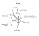
- FIG. 1 is a schematic diagram showing a situation when a medical-solution administration device according to a first embodiment of the present invention is applied to a human body.
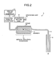
- FIG. 2 is a schematic diagram showing a configuration of the medical-solution administration device illustrated in FIG. 1 .
- a medical-solution administration device 3 discharges and administers, to an affected area 2 such as carcinoma inside a human body 1 as the biological object, a medical solution such as an anticancer drug of fluorouracil (5-FU) of about tens of ml in a continuous and focused manner over a long time period of about one week.
- an anticancer drug of fluorouracil 5-FU
- the medical solution discharged continuously from the medical-solution administration device 3 is administered to the affected area 2 via a feed tube 6 that is inserted in a catheter 5 connecting between the outside of the human body 1 and the affected area 2.
- the medical-solution administration device 3 is portably retained on the human body 1 with a retainer 4 such as a belt. The portability of the medical-solution administration device 3 frees the human body 1 from any restrictions on the movements and enables extended and continuous administration of the medical solution to the affected area 2.
- the medical-solution administration device 3 includes a medical-solution reservoir 10 filled with a medical solution, a driving liquid reservoir 13 filled with a driving liquid that is used in pushing the medical solution, and an electro-osmotic flow pump 12 that is disposed between the driving liquid reservoir 13 and the medical-solution reservoir 10 and that pumps the driving liquid used in pushing the medical solution. Meanwhile, it is preferable to use ultrapure water as the driving water.
- the operating principle of the electro-osmotic is as follows. In an electro-osmotic material (porous body), the surface inside fine pores is charged negatively and in the vicinity of the surface occurs an excess of positive ions. The positive ions become mobile when subject to force due to an electric field applied from outside.
- the electro-osmotic flow pump 12 includes a flow rate setting unit 14 and, corresponding to the flow rate set in the flow rate setting unit 14, generates an electric field for varying the discharging flow rate of the driving liquid.
- An operating unit 15 that is configured using a dial or the like is disposed for specifying the flow rate to be set in the flow rate setting unit 14.
- the medical-solution reservoir 10 is a thin pipe densely-wound into a coil shape of uniform diameter and is filled with a medical solution such as an anticancer drug.
- the driving liquid enters that pipe from the side of the electro-osmotic flow pump 12.
- the medical solution is discharged from the medical-solution reservoir 10 in an indirect manner.
- the medical-solution reservoir 10 is made of a transparent material. Moreover, a colored marker 11 made of red food coloring or the like is placed in at least some portion such as the tip portion of the driving liquid. When the medical solution is discharged, the marker 11 moves over and it is possible to keep track of the amount of movement or the condition of movement of the moving marker 11.
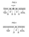
- the marker 11 is placed between a driving liquid 20 and a medical solution 21.
- the driving liquid 20 and the marker 11 is filled oil 22a.
- the driving liquid 20 and the oil 22a is filled air 23a and between the oil 22a and the medical solution 21 is filled air 23b.
- the medical solution 21 and the marker 11 is filled oil 22b.
- the medical solution 21 and the oil 22b is filled air 23d and between the oil 22b and the marker 11 is filled air 23c.
- a scale 16 made of a transparent material.
- the scale 16 can be pasted on the medical-solution reservoir 10 in a seal shape.
- the scale 16 can be used to measure the amount of movement of the marker 11 so that the variation in the flow rate of the medical solution is known.
- the medical-solution reservoir 10 is coiled with a uniform diameter and a uniform pitch, a straight line can be marked along the axial direction for checking the variation in the time taken by the marker 11 to make one round.
- the variation in the flow rate of the medical solution can be found out by checking the variation in the time taken by the marker 11 to make one round at almost the same position.
- any variation in the flow rate of the medical solution is known, then the operator can operate the operating unit 15 to change the flow rate setting value of the flow rate setting unit 14 and make sure that the flow rate is reset to that prior to the occurrence of variation. That eventually makes it possible to administer the total dose of the medical solution that needs to be administered within the administration period.
- variations in the flow rate of a medical solution within the administration period are not known.
- corrections can be made to the administration of the medical solution during the administration period and the total required dose of the medical solution can be administered within the administration period. In this way, it is possible to perform adequate administration of the medical solution.
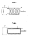
- a driving liquid 30 itself can be made to contain a dye and changes in the position of the tip portion of the driving liquid 30 can be checked to know the variation in the flow rate of the medical solution.
- oil 32 is filled therebetween.
- air 33a between the oil 32 and the driving liquid 30 is filled air 33b.
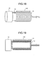
- the driving liquid reservoir 13 can be disposed inside the internal space formed by the coil-shaped pipe of the medical-solution reservoir 10.
- the internal space is cylindrical in shape, it is desirable to manufacture the driving liquid reservoir 13 from, for example, a columnar tube of fluorine contained resin.
- the medical-solution administration device 3 can be reduced in size and can have an enhanced portability.
- the downsized medical-solution administration device 3 can also be implanted in the human body so that the person being administered the medical solution can move around more freely.
- the variation in the flow rate of the medical solution is known on the basis of the amount of movement of the marker 11 and, when there is variation in the flow rate of the medical solution, the operator operates the operating unit 15 to correct the flow rate of the medical solution.
- a line sensor is disposed to detect the amount of movement of the marker 11 and the flow rate of the medical solution is corrected in an automatic manner based on the detection result of the line sensor.
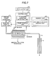
- FIG. 7 is a schematic diagram showing a configuration of the medical-solution administration device according to the second embodiment of the present invention.
- the medical-solution administration device illustrated in FIG. 7 includes a line sensor 40 that detects the amount of movement of the marker 11 disposed inside the medical-solution reservoir 10; a control unit 41 that, based on the detection result of the line sensor 40, at least controls the flow rate of the driving liquid pumped from the electro-osmotic flow pump 12; an input-output unit 42 that is used in issuing a variety of input instructions or settings with respect to the medical-solution administration device and performing output such as display; and a memory unit 43.
- the configuration of the medical-solution administration device is identical to that according to the first embodiment. Hence, the identical constituent elements are referred by the same reference numerals.
- the line sensor 40 is a line image sensor that is disposed along the axial direction of and on the surface of the medical-solution reservoir 10.
- the control unit 41 includes a flow-rate-variation detecting unit 41a that detects variation in the flow rate by performing image processing on the passing of the marker 11.
- the control unit 41 also includes a pump control unit 41b that, on the basis of the variation in the flow rate detected by the flow-rate-variation detecting unit 41a, controls the flow rate of the driving liquid pumped from the electro-osmotic flow pump 12, that is, controls the flow rate of the medical solution. More particularly, the pump control unit 41b performs feedback control to ensure that the medical solution always flows in a constant quantity per unit time. Because of the feedback control, the flow rate of the medical solution can be corrected in a reliable manner.
- control unit 41 can also be configured to perform control so that the total dose of the medical solution is reliably administered within the administration period.
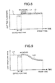
- the control unit 41 performs control based on the temporal profile of a unit time flow rate that is stored in a unit-time flow-rate memory unit 43a of the memory unit 43. For example, as illustrated in FIG. 8 , consider a case of administering the medical solution corresponding to a straight line L that represents a constant quantity of the unit time flow rate within the administration period.
- the unit time flow rate drops at a detection time of the line sensor 40; then, to correct the dropped flow rate, the unit time flow rate can be increased at the subsequent detection time in order to compensate for the decreased quantity of the medical solution and the flow rate can be controlled with the straight line L of the increased unit time flow rate value as the target value.
- the flow rate since the ultimate requirement is to administer the total dose of the medical solution before the administration period is over; it is also possible to control the flow rate, during the period from the point of time at which the drop was detected to the finish time of the administration period, with a straight line L2 of a unit time flow rate value obtained by equalization of the decreased quantity as the target value.
- the feedback control is performed on the quantity of the medical solution decreased in the detection period.
- control unit 41 since the control unit 41 performs the feedback control of the flow rate on the basis of the amount of movement of the marker 11 detected by the line sensor 40, it is possible to reliably administer the total required dose of the medical solution within the administration period.
- the flow rate is changed using the operating unit 15.
- an electro-osmotic flow pump that, in response to variation in the flow rate, pumps the driving liquid at a desired flow rate.
- the feed tube 6 does not generally contain the medical solution.
- an initial setting is performed to fill the medical solution in the feed tube 6. If the flow rate at the time of performing the initial setting is same as the flow rate at the time of administering the medical solution, then it takes a substantial amount of time to fill the medical solution in the feed tube 6.
- the medical solution is discharged with a high flow rate.
- such discharging can be controlled by operating the operating unit 15.
- control unit 41 ensures that the medical solution is discharged with a high flow rate at the time of initial setting.
- the medical-solution reservoir 10 is a thin pipe densely-wound into a coil shape of uniform diameter.
- the medical-solution reservoir 10 can also be a transparent pipe wound not in a circular manner but in a rectangular manner. What matters is that the medical-solution reservoir 10 is transparent so that it is possible to check the amount of movement of the marker.
- the medical-solution reservoir 10 can also be manufactured as a coil-shaped pipe having a tapering diameter.
- the coil-shaped pipe has a uniform gradient along the axial direction. That facilitates easy installation of and easy detection by a line sensor 40a. Meanwhile, the relation between the detection of the marker and the amount of movement of the marker needs to be corrected.
- the marker 11 is assumed to be made of red food coloring. Alternatively, it is also possible to use a colored plastic ball. What matters is that a person is able to visually confirm the marker 11 in the first embodiment and the line sensor 40 is able to detect the marker 11 in the second embodiment.
- the driving liquid reservoir 13 can be disposed inside the internal space of the medical-solution reservoir 10.
- the line sensor 40 can also be disposed inside the internal space of the medical-solution reservoir 10.
- a third embodiment according to the present invention.
- the colored marker 11 and the line sensor 40 that detects the amount of movement of the marker 11.
- the marker 11 and the line sensor 40 are respectively replaced with a magnetic marker 111 and a magnetic line sensor 140 as illustrated in FIG. 12 .
- the configuration is identical to the medical-solution administration device illustrated in FIG. 7 .
- the identical constituent elements are referred by the same reference numerals.
- the magnetic line sensor 140 is disposed along the axial direction of and on the external surface of the medical-solution reservoir 10.
- a biological information sensor 124 is newly disposed in the medical-solution administration device described in the third embodiment with reference to FIG. 12 .
- the biological information sensor 124 detects biological information of the human body 1, which is the biological object being administered the medical solution.
- the biological information includes information on, for example, brain waves, blood components or blood constitutes, and cardiac rate that are related to the condition of the affected area due to the administered medical solution.
- the memory unit 43 includes a biological-information/flow-rate relation memory unit 143a in place of the unit-time flow-rate memory unit 43a.
- the biological-information/flow-rate relation memory unit 143a is stored, as illustrated in FIG. 15 , the relation between a biological information value detected by the biological information sensor 124 and the unit time flow rate of the medical solution.
- the biological-information/flow-rate relation memory unit 143a can be configured to store the temporal profile that is the time variation of the unit time flow rate as illustrated in the lower graphs in FIGS. 16 and 17 .
- control unit 41 also includes a biological information detecting unit 41c that detects the biological information value based on the value detected by the biological information sensor 124.
- the flow-rate-variation detecting unit 41a in the control unit 41 detects variation in the flow rate of the medical solution when the magnetic line sensor 140 detects the passing of the magnetic marker 111.
- the pump control unit 41b in the control unit 41 obtains the unit time flow rate based on the biological information value detected by the biological information detecting unit 41c and the biological-information/flow rate relation stored in the biological-information/flow-rate relation memory unit 143a.
- the pump control unit 41b controls the flow rate of the driving liquid pumped from the electro-osmotic flow pump 12, that is, controls the flow rate of the medical solution in such a way that the variation in the flow rate detected by the flow-rate-variation detecting unit 41a becomes equal to the obtained unit time flow rate.
- the control unit 41 performs pump control based on, for example, the biological-information/flow rate relation illustrated in FIG. 15 .
- the control unit 41 performs feedback control based on the detection result of the flow-rate-variation detecting unit 41a so that the medical solution is administered at the unit time flow rate corresponding to the detected biological information value along a characteristic curve L21 illustrated by a solid line.
- a dashed curve line L22 in FIG. 15 it is also possible to perform control so that the unit time flow rate becomes discrete values corresponding to the biological information value.
- the control unit 41 attempts to perform feedback control with the biological-information/flow rate relation as the target value.
- the flow rate of the medical solution can be controlled in a feedforward manner on the basis of the detection result of the biological information detecting unit 41c and the biological-information/flow rate relation.
- control unit 41 controls the flow rate of the medical solution using the biological information, the medical solution can be adequately administered according to the condition of the biological object while ensuring that there is no adverse effect on the biological object. That enables achieving enhancement in the impact of the medical-solution administration according to the condition of the biological object.
- a sensor that detects the value of deviation enzymes such as AST (aspartate aminotransferase) and ALT (alanine aminotransferase) in the liver can be disposed as the biological information sensor 124.
- the control unit 41 can perform control to reduce the unit time flow rate during administration of the medical solution.
- a sensor that detects a serum creatinine value indicating a type of waste material present in the blood can be disposed as the biological information sensor 124. In that case, if the detected serum creatinine value shows a rise; then, based on the biological-information/flow rate relation corresponding to an estimation result indicating impaired liver functioning, the control unit 41 can perform control to reduce the unit time flow rate during administration of the medical solution.
- the biological information sensor 124 can be configured to measure the level of PSA (prostate specific antigen), which is a type of prostate-specific protein, in the blood. Then, based on that blood level value, the control unit 41 controls the unit time flow rate during administration of the medical solution on the basis of the biological-information/flow rate relation corresponding to the effectiveness of the treatment.
- PSA state specific antigen
- the temporal profile of the unit time flow rate can be stored in the biological-information/flow rate relation and the control unit 41 can be configured to control the flow rate using that temporal profile.
- a temporal profile LT of the unit time flow rate of the medical solution is stored in addition to the biological-information/flow rate relation.
- control unit 41 controls the flow rate of the medical solution to ensure that the unit time flow rate is equal to that indicated by the temporal profile LT at a time t2, which comes after the time t1 by a time interval TS.
- the control unit 41 controls the flow rate of that medical solution corresponding to the temporal profile LT immediately after the time t1.
- control unit 41 can be configured to correct, according to a curve line L31 representing the detection result of the biological information value, a temporal profile L41 illustrated in the lower graph in FIG. 17 to an optimal temporal profile L44 in response to the condition of the biological object, and then control the flow rate of the medical solution based on the temporal profile L44.
- the correction percentage of the temporal profile L41 is varied, in other words, positive and negative weighting is performed, and the temporal profile L41 is corrected to the temporal profile L44.
- the biological information sensor 124 performs direct and real-time detection of the biological information of the human body 1.
- indirect detection on the outside of the body is also possible as long as the biological information is detected in almost real time.
- the control unit 41 can also be configured to display information such as the above-mentioned biological information value, the temporal variation in the biological information value, and the flow rate control status on a display unit (not illustrated) disposed in the input-output unit 42.
- the electro-osmotic flow pump 12 can be equipped with an offline flow rate setting unit (not illustrated) that is not kept under the control of the control unit 41. In that case, the operations are performed manually with an operating unit configured using a dial or the like.
- the driving liquid reservoir 13 can be disposed inside the internal space of the medical-solution reservoir 10.
- the magnetic line sensor 140 can also be disposed inside the internal space of the medical-solution reservoir 10. Alternatively, it is also possible to dispose only the magnetic line sensor 140 inside the internal space of the medical-solution reservoir 10.
- the magnetic marker 11 is disposed inside the medical-solution reservoir 10 and the variation in the flow rate of the medical solution is detected by the magnetic line sensor 20 based on the amount of movement of the magnetic marker 11.
- the line sensor 40 can also be used as the line image sensor for detecting the colored marker 11 inside the medical-solution reservoir 10 and the flow rate can be controlled based on the detection result.
- the configuration illustrated in FIG. 21 corresponds to that in the fourth embodiment.
- the quantity of the driving liquid discharged from the driving liquid reservoir 13 via the electro-osmotic flow pump 12 is set to be smaller than the quantity of the medical solution filled in the medical-solution reservoir 10.
- the driving liquid runs short before the rear end portion of the medical solution being discharged reaches the delivery side fore-end of the medical-solution reservoir 10. For that reason, the driving liquid is no more discharged and the medical solution reliably stops from flowing beyond the delivery side fore-end of the medical-solution reservoir 10. That enables forestalling of the driving liquid from being administered.into the human body 1.
- the quantity of the driving liquid filled in the driving liquid reservoir 13 is smaller than the quantity of the medical solution filled in the medical-solution reservoir 10.
- a liquid quantity Qout that can be supplied to the electro-osmotic flow pump 12 is kept smaller than the quantity of the medical solution filled in the medical-solution reservoir 10.
- a liquid quantity Qs is present in actuality at the corners inside the tank of the driving liquid reservoir 13.
- a stop 10a is disposed in the flow path beyond the delivery side fore-end of the medical-solution reservoir 10.
- the stop 10a acts as a blocking member for the flow path toward outside of the biological object. That is, the stop 10a traps the magnetic marker 111 placed between the driving liquid 20 and the medical solution 21 and prevents the driving liquid 20 from being discharged. That enables forestalling of the driving liquid 20 from being administered into the human body 1.
- the stop 10a can also be made of a metal for trapping the magnetic marker 111 so that the driving liquid 20 can be reliably prevented from being administered.
- the magnetic marker 111 is placed between the driving liquid 20 and the medical solution 21.
- a spacer that is of a trappable size in the stop 10a and that is movable inside the flow path can be disposed between the driving liquid 20 and the medical solution 21.
- the stop 10a can be replaced with a net inside the tube, or a ring that can be fit inside the tube, or a pin across the tube; because what matters is that the movable spacer such as the magnetic marker 111 is trapped at the position of the stop 10a and the driving liquid is prevented from being discharged.
- the flow-rate-variation detecting unit 21a detects variation in the flow rate of the medical solution based on the position of the magnetic marker 111 detected by the magnetic line sensor 140. Then, based on those detection results, the pump control unit 21b controls the flow rate of the driving liquid pumped from the electro-osmotic flow pump 12.
- the pump control unit 21b determines whether the driving liquid 20 has been discharged in the flow path that is beyond the delivery side fore-end of the medical-solution reservoir 10 and outside of the biological object.
- the pump control unit 21b performs control so that the electro-osmotic flow pump 12 stops pumping of the driving liquid 20. By performing such control, the driving liquid 20 can be reliably prevented from being administered into the human body 1.
- the control for stopping the driving of the electro-osmotic flow pump 12 performed by the pump control unit 21b is not dependent only on the detection of variation in the flow rate of the medical solution.
- the flow rate of the driving liquid 20 pumped from the electro-osmotic flow pump 12 can be detected and the position of the tip portion of the driving liquid 20 can be estimated based on that detection result. If it is determined that the tip portion of the driving liquid 20 has reached the flow path that is beyond the delivery side fore-end of the medical-solution reservoir 10 and outside of the biological object, then control can be performed so that the electro-osmotic flow pump 12 stops pumping of the driving liquid 20.
- a remaining quantity sensor can be disposed to detect the quantity of the driving liquid remaining in the driving liquid reservoir 13 and if, based on the detection result of the remaining quantity sensor, it is determined that the leading end of the driving liquid has reached the flow path that is beyond the delivery side fore-end of the medical-solution reservoir 10 and outside of the biological object, then control can be performed so that the electro-osmotic flow pump 12 stops pumping of the driving liquid 20.
- the medical-solution reservoir 10 and the catheter 5 are connected via a connecting unit 106, which can be configured to include a check valve that allows the medical solution flow only from the medical-solution reservoir 10 toward the catheter 5. Hence, it becomes possible to prevent overflow of bodily fluids from the human body 1.
Landscapes
- Health & Medical Sciences (AREA)
- Hematology (AREA)
- Life Sciences & Earth Sciences (AREA)
- Vascular Medicine (AREA)
- Engineering & Computer Science (AREA)
- Anesthesiology (AREA)
- Biomedical Technology (AREA)
- Veterinary Medicine (AREA)
- Public Health (AREA)
- Heart & Thoracic Surgery (AREA)
- Animal Behavior & Ethology (AREA)
- General Health & Medical Sciences (AREA)
- Physics & Mathematics (AREA)
- Fluid Mechanics (AREA)
- Infusion, Injection, And Reservoir Apparatuses (AREA)
- Containers And Packaging Bodies Having A Special Means To Remove Contents (AREA)
Applications Claiming Priority (5)
| Application Number | Priority Date | Filing Date | Title |
|---|---|---|---|
| JP2007264775 | 2007-10-10 | ||
| JP2007264776 | 2007-10-10 | ||
| JP2007264777 | 2007-10-10 | ||
| JP2008076727 | 2008-03-24 | ||
| PCT/JP2008/068490 WO2009048144A1 (ja) | 2007-10-10 | 2008-10-10 | 薬液投与装置 |
Publications (1)
| Publication Number | Publication Date |
|---|---|
| EP2204202A1 true EP2204202A1 (de) | 2010-07-07 |
Family
ID=40549288
Family Applications (1)
| Application Number | Title | Priority Date | Filing Date |
|---|---|---|---|
| EP08838161A Withdrawn EP2204202A1 (de) | 2007-10-10 | 2008-10-10 | Spender für medizinische lösung |
Country Status (5)
| Country | Link |
|---|---|
| US (1) | US20100191223A1 (de) |
| EP (1) | EP2204202A1 (de) |
| JP (1) | JP5302205B2 (de) |
| CN (1) | CN101820934B (de) |
| WO (1) | WO2009048144A1 (de) |
Families Citing this family (11)
| Publication number | Priority date | Publication date | Assignee | Title |
|---|---|---|---|---|
| WO2009119519A1 (ja) * | 2008-03-24 | 2009-10-01 | オリンパス株式会社 | 薬剤投与装置 |
| JP5719767B2 (ja) | 2008-05-08 | 2015-05-20 | ミニパンプス, エルエルシー | 埋込型ポンプおよびそのためのカニューレ |
| US9333297B2 (en) | 2008-05-08 | 2016-05-10 | Minipumps, Llc | Drug-delivery pump with intelligent control |
| WO2011022484A1 (en) * | 2009-08-18 | 2011-02-24 | Replenish Pumps. Llc | Electrolytic drug-delivery pump with adaptive control |
| WO2014006197A1 (en) | 2012-07-06 | 2014-01-09 | Sanofi-Aventis Deutschland Gmbh | Drug delivery device |
| CN102847201B (zh) * | 2012-09-04 | 2014-07-30 | 深圳市卫邦科技有限公司 | 用于配药系统中的输液软管装填移载及药液分配装置 |
| DE102018211392A1 (de) * | 2018-07-10 | 2020-01-16 | B. Braun Melsungen Ag | Infusionsanordnung zur Verabreichung eines medizinischen Fluids |
| MX2022007512A (es) * | 2019-12-19 | 2022-09-19 | Janssen Biotech Inc | Bombas con accesibilidad de fármaco líquido independiente de la orientación. |
| JP6744527B1 (ja) * | 2020-04-01 | 2020-08-19 | アットドウス株式会社 | 薬液投与ユニット、薬液投与モジュール、薬液投与装置、及び投薬管理システム |
| JP6948047B1 (ja) * | 2021-06-20 | 2021-10-13 | アットドウス株式会社 | 薬液投与装置、薬液管理装置、薬液管理システム、薬液管理プログラム、記録媒体、及び薬液管理方法 |
| CN113905565B (zh) * | 2021-10-18 | 2023-11-10 | Oppo广东移动通信有限公司 | 壳体、外壳组件以及电子设备 |
Family Cites Families (6)
| Publication number | Priority date | Publication date | Assignee | Title |
|---|---|---|---|---|
| JPS5854962A (ja) * | 1981-09-27 | 1983-04-01 | テルモ株式会社 | 注出ポンプ |
| US4854324A (en) * | 1984-01-31 | 1989-08-08 | Medrad, Inc. | Processor-controlled angiographic injector device |
| US5827219A (en) * | 1993-10-28 | 1998-10-27 | Medrad, Inc. | Injection system and pumping system for use therein |
| US5840026A (en) * | 1994-09-21 | 1998-11-24 | Medrad, Inc. | Patient specific dosing contrast delivery systems and methods |
| US7963956B2 (en) * | 2003-04-22 | 2011-06-21 | Antisense Pharma Gmbh | Portable equipment for administration of fluids into tissues and tumors by convection enhanced delivery technique |
| KR100858072B1 (ko) * | 2004-02-26 | 2008-09-11 | 니프로 가부시키가이샤 | 안전 유치 바늘 |
-
2008
- 2008-10-10 EP EP08838161A patent/EP2204202A1/de not_active Withdrawn
- 2008-10-10 JP JP2009537044A patent/JP5302205B2/ja not_active Expired - Fee Related
- 2008-10-10 CN CN2008801104176A patent/CN101820934B/zh not_active Expired - Fee Related
- 2008-10-10 WO PCT/JP2008/068490 patent/WO2009048144A1/ja active Application Filing
-
2010
- 2010-04-05 US US12/754,073 patent/US20100191223A1/en not_active Abandoned
Non-Patent Citations (1)
| Title |
|---|
| See references of WO2009048144A1 * |
Also Published As
| Publication number | Publication date |
|---|---|
| CN101820934B (zh) | 2012-09-05 |
| JPWO2009048144A1 (ja) | 2011-02-24 |
| CN101820934A (zh) | 2010-09-01 |
| US20100191223A1 (en) | 2010-07-29 |
| WO2009048144A1 (ja) | 2009-04-16 |
| JP5302205B2 (ja) | 2013-10-02 |
Similar Documents
| Publication | Publication Date | Title |
|---|---|---|
| EP2204202A1 (de) | Spender für medizinische lösung | |
| JP7174089B2 (ja) | 液剤を投薬する計量システムを有するポンプ・エンジン | |
| EP3012600B1 (de) | Dosiervorrichtung für ein infusionssystem | |
| US5462525A (en) | Flow sensor for an infusion pump | |
| US8007247B2 (en) | End of stroke detection for electromagnetic pump | |
| US8083730B2 (en) | Implantable therapeutic substance delivery device with reservoir volume sensor | |
| US20080287874A1 (en) | Controlling dead volume of a piston pump using an adjustment screw | |
| US11147931B2 (en) | Drug delivery device with air and backflow elimination | |
| US10449306B2 (en) | Systems for fluid delivery with wicking membrane | |
| US10188789B2 (en) | Fluid infusion device with safety coupling | |
| US10905821B2 (en) | Capacitor detection for IV pump tube calibration | |
| US11504469B2 (en) | Reed switch detection for IV pump tube calibration | |
| US10898640B2 (en) | Visual detection for IV pump tube calibration | |
| US20230029043A1 (en) | Flowrate control for self-pressurized reservoir of a device for delivering medication | |
| JP2023532176A (ja) | 薬物送達システム |
Legal Events
| Date | Code | Title | Description |
|---|---|---|---|
| PUAI | Public reference made under article 153(3) epc to a published international application that has entered the european phase |
Free format text: ORIGINAL CODE: 0009012 |
|
| 17P | Request for examination filed |
Effective date: 20100409 |
|
| AK | Designated contracting states |
Kind code of ref document: A1 Designated state(s): AT BE BG CH CY CZ DE DK EE ES FI FR GB GR HR HU IE IS IT LI LT LU LV MC MT NL NO PL PT RO SE SI SK TR |
|
| AX | Request for extension of the european patent |
Extension state: AL BA MK RS |
|
| DAX | Request for extension of the european patent (deleted) | ||
| STAA | Information on the status of an ep patent application or granted ep patent |
Free format text: STATUS: THE APPLICATION HAS BEEN WITHDRAWN |
|
| 18W | Application withdrawn |
Effective date: 20120731 |