EP2204130A1 - Cutting tool and osteosynthesis set - Google Patents
Cutting tool and osteosynthesis set Download PDFInfo
- Publication number
- EP2204130A1 EP2204130A1 EP08106039A EP08106039A EP2204130A1 EP 2204130 A1 EP2204130 A1 EP 2204130A1 EP 08106039 A EP08106039 A EP 08106039A EP 08106039 A EP08106039 A EP 08106039A EP 2204130 A1 EP2204130 A1 EP 2204130A1
- Authority
- EP
- European Patent Office
- Prior art keywords
- cutting
- bone plate
- jaw
- cutting edge
- tool according
- Prior art date
- Legal status (The legal status is an assumption and is not a legal conclusion. Google has not performed a legal analysis and makes no representation as to the accuracy of the status listed.)
- Withdrawn
Links
Images


Classifications
-
- A—HUMAN NECESSITIES
- A61—MEDICAL OR VETERINARY SCIENCE; HYGIENE
- A61B—DIAGNOSIS; SURGERY; IDENTIFICATION
- A61B17/00—Surgical instruments, devices or methods, e.g. tourniquets
- A61B17/56—Surgical instruments or methods for treatment of bones or joints; Devices specially adapted therefor
- A61B17/58—Surgical instruments or methods for treatment of bones or joints; Devices specially adapted therefor for osteosynthesis, e.g. bone plates, screws, setting implements or the like
- A61B17/88—Osteosynthesis instruments; Methods or means for implanting or extracting internal or external fixation devices
- A61B17/8863—Apparatus for shaping or cutting osteosynthesis equipment by medical personnel
-
- A—HUMAN NECESSITIES
- A61—MEDICAL OR VETERINARY SCIENCE; HYGIENE
- A61B—DIAGNOSIS; SURGERY; IDENTIFICATION
- A61B17/00—Surgical instruments, devices or methods, e.g. tourniquets
- A61B17/56—Surgical instruments or methods for treatment of bones or joints; Devices specially adapted therefor
- A61B17/58—Surgical instruments or methods for treatment of bones or joints; Devices specially adapted therefor for osteosynthesis, e.g. bone plates, screws, setting implements or the like
- A61B17/68—Internal fixation devices, including fasteners and spinal fixators, even if a part thereof projects from the skin
- A61B17/80—Cortical plates, i.e. bone plates; Instruments for holding or positioning cortical plates, or for compressing bones attached to cortical plates
- A61B17/8085—Cortical plates, i.e. bone plates; Instruments for holding or positioning cortical plates, or for compressing bones attached to cortical plates with pliable or malleable elements or having a mesh-like structure, e.g. small strips
Definitions
- the present invention relates to a cutting tool for cutting bone plates and an osteosynthesis set with at least one bone plate and at least one cutting tool.
- Bone plates used in the field of osteosynthesis are available in a wide variety of sizes and shapes. Nevertheless, it is often necessary for a surgeon to adapt such bone plates to the individual anatomy of a patient or to the actual bone fracture or defect present. For this purpose, especially intraoperatively cutting tools, such as cutting forceps used to cut the bone plates at a suitable location and thus provide a bone plate part with a desired size and shape.
- a generic cutting pliers is already in DE 43 08 319 disclosed.
- the cutting pliers described there have two handle levers, each with an attached cutting jaw. Both cutting jaws each have a cutting edge.
- a bone plate to be cut can be brought into a cutting position in which it can be severed by means of the two cutting edges along a cut surface.
- the cutting pliers On one of the two cutting jaws, the cutting pliers have a support surface and a hold-down, between which the bone plate can be fixed, so that when cutting no tilting or deformation of the bone plate occurs.
- the support surface has a protruding from her retaining pin on which a through hole of the bone plate, such as a screw hole, are inserted can, which leads to a further determination of the bone plate during cutting.
- the arrangement and the dimensions of the retaining pin considerably limit the selection of the bone plates which can be severed with this incisor.
- the inner diameter of the passage opening must be matched to the outer diameter of the retaining pin.
- the spacing between the cutting surface and the through-opening of the bone plate is determined by the distance of the retaining pin from the cutting edge.
- no bone plates can be cut, in which the distance between two adjacent passage openings corresponds to the distance between the retaining pin and cutting edge; In this case, would define the border of the other through hole when setting the one through hole on the retaining pin and leave two partial webs of the border, which protrude from the bone plate.
- the retaining pin can damage a possible inner contour of the through hole.
- the cutting tool according to the invention serves to sever bone plates.
- the cutting tool may be a cutting pliers.
- the cutting tool includes at least a first cutting edge and at least one second cutting edge, by means of which the bone plate can be severed in at least one cutting position along a first cutting surface.
- the severing takes place by a shearing movement, in which the first cutting edge and the second cutting edge are moved past each other in a sufficiently small distance.
- the cutting tool comprises at least one hold-down device, which is designed and arranged such that, when the bone plate is severed, bending of the bone plate is substantially prevented by contact of the hold-down with the bone plate.
- the hold-down can be designed and arranged such that a bending in the region of the cut surface is prevented.
- the hold-down device is designed and arranged in such a way that the bone plate can be brought into the cutting position essentially in a straight line in an insertion direction.
- the Bone plate can thus be brought by a substantially rectilinear movement in a position in which it is severable by means of the first cutting edge and the second cutting edge.
- the rectilinear insertability does not exclude here and below that the bone plate can alternatively be inserted in a straight line in a non-rectilinear manner or in two different directions; However, it must be possible within the scope of the invention to be able to introduce the bone plate essentially in a straight line in at least one manner.
- the substantially straight-line introducibility in the insertion direction requires that the bone plate is displaceable in this insertion direction. Consequently, it is possible to bring the bone plate along the insertion direction in different cutting positions relative to the first cutting edge and the second cutting edge, each defining a different sectional area of the bone plate. This allows a very individual severing of a given bone plate.
- the substantially straightforward introducibility also implies the lack of devices that could prevent this straightforward insertion, such as the in DE 43 08 319 existing retaining pin.
- the usability of the inventive cutting tool is therefore not on bone plates with specific diameters of the through holes or certain Distances of the same limited. Consequently, the inventive cutting tool is much more versatile than that in DE 43 08 319 shown.
- the first and the second cutting edge are moved past each other.
- Contact of the bone plate with the hold down causes the bone plate to not substantially bend during this movement.
- the bone plate is thus supported on the hold-down during cutting.
- unwanted oblique and / or sharp-edged cut surfaces are avoided, which could be caused by excessive bending.
- the first cutting edge and the second cutting edge are rotatable or pivotable about a cutting rotational axis.
- the severing then takes place by means of a twisting or pivoting of the first cutting edge relative to the second cutting edge, whereby the first cutting edge and the second cutting edge are moved past each other.
- the second cutting edge it is also possible and within the scope of the invention for the second cutting edge to be movable essentially in a straight line relative to the first cutting edge. The severing then takes place by means of this rectilinear movement of the first cutting edge relative to the second cutting edge.
- the insertion direction is substantially perpendicular to the cutting axis of rotation.
- the insertion direction is substantially perpendicular to the cutting axis of rotation.
- Such an abutment which could occur, for example, in Y-shaped or N-shaped bone plates, could sometimes completely prevent insertion into the cutting position, which would make the cutting tool unusable for this bone plate.
- the cutting tool comprises a first cutting jaw containing the first cutting edge and a second cutting jaw containing the second cutting edge.
- the second cutting jaw can thereby be rotatable or pivotable relative to the first cutting jaw by means of a cutting-side joint defining the cutting rotational axis.
- the first cutting edge can be worked directly into the first cutting jaw, and / or the second cutting edge can be worked directly into the second cutting jaw.
- the first cutting jaw has a bearing surface for the bone plate. This can be designed and arranged such that in the cutting position, at least part of the bone plate is in contact with the support surface and is positioned between the support surface and the hold-down. In this way, the part of the bone plate before and / or when cutting on the support surface rest, which allows a safer positioning and prevents unintentional displacement of the bone plate during the severing.
- the bearing surface is substantially complementary at least to a part of the surface of the bone plate. Inadvertent displacement of the bone plate during cutting can thereby be effectively avoided.
- the support surface may also be substantially planar. If a part of the surface of the bone plate has a convex curvature, the bearing surface can be correspondingly concave-shaped.
- the hold-down is connected to the first cutting jaw.
- it may be rigidly connected to the first cutting jaw.
- the hold-down is movably connected to the first cutting jaw and is rigidly fixable only for cutting on the first cutting jaw, for example by means of a correspondingly formed locking device. This may be particularly advantageous if bone plates are to be severed with different thicknesses.
- the hold-down of the first cutting jaw is solvable. In particular, it can then be replaced by another hold-down, which is better suited for a particular bone plate.
- various hold-downs may have different dimensions or be designed such that they can be positioned in different positions, in particular distances relative to the support surface.
- the various hold-downs may form differently shaped and / or dimensioned interstices for insertion of a bone plate, such as curved or semicircular.
- the hold-down is arranged on the second cutting jaw.
- the hold-down is then resiliently mounted on the second cutting jaw so that it first comes into contact with the bone plate when initiating the shearing movement and pushes the bone plate in the further shearing movement due to the suspension against the first cutting jaw.
- the hold-down device preferably comprises a transverse web, which can extend in particular substantially perpendicular to the insertion direction.
- the cross bar is designed and arranged such that when cutting the bone plate bending of the bone plate is substantially prevented by contact of the cross bar with the bone plate.
- the transverse web is fastened by means of at least one retaining web to the first cutting jaw.
- the transverse web is fastened by means of second lateral retaining webs on the first cutting jaw. This allows a material-saving and at the same time stable attachment of the crosspiece to the cutting jaw.
- the length of the cross bar is preferably adapted to the width of bone plates commonly used in osteosynthesis. Accordingly, it preferably has a length between 1 mm and 15 mm, more preferably between 2 mm and 10 mm, particularly preferably between 3.2 mm and 7.5 mm.
- the cutting tool has a first handle lever, which is rigidly or hingedly connected to the first cutting jaw. Further preferably, it has a second handle lever, which is rigidly or hingedly connected to the second cutting jaw.
- first handle lever and the second handle lever are rotatably connected to each other via a handle-side joint.
- the first cutting edge and the second cutting edge are at least partially curved, in particular circular arc-shaped. This allows severing along a cut surface corresponding to this arc shape.
- the first cutting edge and the second cutting edge are bent outward relative to the insertion direction of the bone plate.
- the radius of the arcuate portion of the first cutting edge and / or the second cutting edge in the range of 0.5 mm to 7.5 mm, preferably from 2 mm to 6.5 mm, more preferably from 4 mm to 5.5 mm ,
- the cutting tool is designed such that at least in the cutting position, the first cutting edge and / or the second cutting edge are visible. This greatly simplifies the correct positioning of the bone plate, since the position of the expected due to the position of the cutting edges cutting surface is recognizable.
- the cutting tool is preferably designed such that at least one of the resulting when cutting the bone plate bone plate parts from the cutting tool durable, in particular clamped.
- the bone plate part may be durable or clampable during and after severing between a first holding surface on the first cutting jaw and a second holding surface on the second cutting jaw. The other part of the bone plate resulting from cutting can be comfortably held in one hand, while the cutting tool is held in the other hand.
- Some embodiments of the cutting tool according to the invention additionally include a wire cutting device for cutting through an elongated object, for example a surgical wire.
- the wire cutting device comprises a first wire cutting edge and a second wire cutting edge.
- the first wire cutting edge is movable relative to the second wire cutting edge, in particular rotatable or pivotable, that the elongate object of the first wire cutting edge and the second wire cutting edge is severed.
- the first wire cutting edge may in particular be rigidly connected to the first cutting jaw; the second wire cutting edge may be rigidly connected to the second cutting jaw.
- the first wire cutting edge is pivotable about the cutting axis of rotation. This makes it possible that by the same pivoting movement between the first cutting jaw and the second cutting jaw on the one hand cutting a bone plate by means of the first cutting edge and the second cutting edge and on the other hand, a severing of an elongated article by means of the first wire cutting edge and the second wire cutting edge can be achieved.
- the materials and dimensions of the cutting tool may be selected according to their use for cutting bone plates.
- the dimensions of the cutting tool in particular the dimensions of the first and second cutting surfaces, the support surface and the blank holder are adapted to the dimensions of bone plates which are commonly used in osteosynthesis.
- the materials are selected so that they can withstand the forces occurring during the cutting of the bone plate. If, for example, the cutting tool is to be suitable for severing a bone plate made of titanium, the first and second cutting surfaces, for example, must have sufficient mechanical strength.
- an osteosynthesis set which contains at least one bone plate and at least one cutting tool according to the invention.
- the osteosynthesis set can also contain at least two mutually different bone plates.
- the at least one bone plate of the osteosynthesis set is designed so that it can be severed with the aid of the cutting tool.
- it is dimensioned in such a way that it can be brought into the cutting position substantially rectilinearly in an insertion direction.
- at least a part of the surface of the bone plate may be complementary to the bearing surface of the cutting tool.
- Another aspect of the invention relates to the use of a cutting tool according to the invention for severing a bone plate.
- FIGS. 1a to 1c show three different views of a cutting tool according to the invention, which is designed as a cutting pliers 1.
- a cutting tool according to the invention, which is designed as a cutting pliers 1.
- the cutting pliers 1 a first handle lever 13 which is hingedly connected via a first lever joint 15 with a first cutting jaw 7.
- the cutting pliers 1 further comprises a second handle lever 14 which is hingedly connected via a second lever joint 16 with a second cutting jaw 8.
- the first handle lever 13 and the second handle lever 14 are connected to each other via a handle-side joint 23 which defines a cutting axis of rotation.
- the first handle lever 13 and the second handle lever 14 are biased by two springs 29 and counteract a compression of the two handle levers 13, 14.
- the first cutting jaw 7 has a first cutting element 21 (see FIG. 2 ) with a first cutting edge 2.
- the second cutting jaw 8 has a second cutting element 22 (see FIG. 2 ) with a second cutting edge 3.
- the front surface 30 of the second cutting element 22 is at an angle of 8 ° a perpendicular to the second cutting jaw 8 inclined (see. FIGS. 3b and d ).
- the first cutting edge 2 and the second cutting edge 3 are rotatable relative to each other about the cutting rotational axis defined by a cutting-side joint 9.
- the arrangement of the joint 9 and other joints 15, 16, 23 ensures a particularly suitable implementation of the forces.
- a hold-down 6 is arranged, which is rigidly connected to the first cutting jaw 7; its structure and function are explained in detail below.
- the cutting pliers 1 has in the in FIG. 1a illustrated position of the joints 9, 15, 16 and 23 has a length 1 over all of 207 mm and a width b over all of 79 mm.
- the first handle lever 13 has a first handle lever end 24, which faces away from the first cutting jaw 7.
- the second handle lever 14 has a second handle lever end 25, which faces away from the second cutting jaw 8. Between the first handle lever end 24 and the second handle lever end 25 is in the in FIG. 1a shown position a distance a of 66 mm.
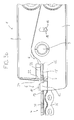
- FIG. 1b shows a side view of the cutting pliers 1.
- the thickness d over all of the cutting pliers 1 in the region of the handle lever 13, 14 is 16 mm.
- the thickness e of the first cutting jaw 7 and the second cutting jaw 8 is 11.4 mm in each case.
- the holding-down device 6 arranged on the first cutting jaw 7 has a transverse web 11.
- the crosspiece 11 is attached by means of two lateral holding webs 12 on the first cutting jaw 7.
- FIG. 2 is a perspective detailed view of the cutting pliers 1 is shown.
- the first cutting element 21 of the first cutting jaw 7 includes a first cutting edge 2;
- the second cutting element 22 of the second cutting jaw 8 contains a Both the first cutting edge 2 and the second cutting edge 3 are partially formed as a circular arc, the circular arc of the second cutting edge 3 has a radius of 4.8 mm and the circular arc of the first cutting edge 2 has a radius of 4.7 mm having.
- the crossbar 11 is fastened by means of two holding webs 12 on the first cutting jaw 7.
- the first cutting element 21 of the first cutting jaw 7 furthermore contains a bearing surface 10. The end of the bearing surface facing the cutting-side joint 9 is formed by the first cutting edge 2.
- FIGS. 3a to d show the cutting forceps 1 with a bone plate 4 with two juxtaposed tabs 31, 31 ', of which only the tab 31 is to be severed.
- the bone plate 4 was in a direction of insertion E straight into the in FIG. 3a shown cutting position S brought.
- the insertion direction E is perpendicular to the cutting axis of rotation, which is defined by the cutting side hinge 9.
- a portion of the flap 31 of the bone plate 4 has been moved through the gap, which is enclosed by the transverse web 11, the two retaining webs 12 and the bearing surface 10.
- the other tab 31 ' was laterally guided past the cutting jaws 7 and 8.
- the rectilinear motion is hindered by no further components of the cutting pliers 1, such as holding pins.
- the bone plate 4 is therefore freely positionable along the insertion direction E to a certain extent.
- the gap between the transverse web 11, retaining webs 12 and bearing surface 10 is dimensioned such that the bone plate 4 shown here is also rotatable to a certain extent.
- the crosspiece 11 of the hold-down 6 extends perpendicular to the insertion direction E.
- the bone plate 4 can thus be inserted in a direction perpendicular to the crosspiece 11 and is aligned perpendicular thereto in the illustrated cutting position S, which is a bending of the tab 31 of the bone plate 4 during cutting particularly effectively prevented.
- the cutting position S according to FIG. 3a is a part of the tab 31 of the bone plate 4 in contact with the support surface 10 and positioned opposite to the cross bar 11 of the hold-6.
- the support surface 10 is formed substantially complementary to the surface on the underside of the bone plate 4. Inadvertent displacement of the bone plate 4 during cutting can thereby be effectively avoided.
- the cross bar 11 has a length of 11.4 mm, a measured in the direction of insertion direction E width of 2.9 mm and a perpendicular thickness of 1.4 mm.
- the two holding webs 12 each have a measured in the insertion direction E width of 1.7 mm and a perpendicular thickness, which is at the crosspiece 11 facing the end of 2.9 mm and at the end facing away from the cross bar 11 4.5 mm.
- FIG. 3b a part of the cutting forceps 1 is shown in a side view, in which the inclination of the front surface 30 of the second cutting element 22 can be seen by 8 °. In this viewing direction, both the first cutting edge 2 and the second cutting edge 3 are visible in the illustrated cutting position S, which considerably simplifies the correct positioning of the bone plate 4 with respect to the cutting surface to be produced.
- the second cutting edge 3 is moved past the first cutting edge 2.
- a first bone plate part 17 'of the tab 31 is separated from a second bone plate part 17 of the tab 31.
- the first bone plate part 17 ' is clamped when severing between a first holding surface 26 on the first cutting jaw 7 and a second holding surface 27 on the second cutting jaw 8.
- This bone plate part 17 'can thus not fall down when cutting or even uncontrollably thrown away from the cutting pliers 1.
- the first bone plate part 17 'can be released again.
- first wire cutting edge 18 is arranged on the first cutting jaw 7
- second wire cutting edge 19 is arranged on the second cutting jaw 8.
- the first wire cutting edge 18 and the second wire cutting edge 19 form a wire cutting device for severing an elongated article, such as a surgical wire. Further structural details and the operation of the wire cutting device are in connection with the FIGS. 4a and b explained below.
- the Figure 3c shows a further perspective view of the cutting forceps 1 and the bone plate 4, in which the first cutting element 21 with the first cutting edge 2 and the second cutting element 22 with the second cutting edge 3 can be seen.
- FIG. 3d figure is a plan view of a portion of the cutting pliers 1 shown.
- the second cutting edge 3 is well visible due to the inclination of the front surface 30 of the second cutting element 22 in this direction of view, which facilitates the positioning of the bone plate 4.
- the bone plate 4 is arranged in such a cutting position S that the cut surface 5 to be generated at least approximately continues the outer edge of the annular border 28 of a through-hole.
- the wire cutting device is shown in two perspective views.
- the first cutting jaw 7 has an arcuate oblong hole 33 on its front side. Through the slot 33 through the arranged on the second cutting jaw 8 second wire cutting edge 19 and a circular hole 34 on the back of the first cutting jaw 7 can be seen.
- FIG. 4b is shown has the circular hole 34 at the rear the first cutting jaw 7, a first wire cutting edge 18, which also encloses the wire insertion opening 32.
- the elongated hole 33 on the front side, the second wire cutting edge 19 and the circular hole 34 on the back surround a wire insertion opening 32.
- the first wire cutting edge 18 and the second wire cutting edge 19 are each semicircular arc-shaped and pivotable about the cutting side hinge 9 against each other.
- this object is first introduced into the wire insertion opening 32 to a desired depth.
- the first handle lever 13 and the second handle lever 14 of the cutting pliers 1 are moved towards each other, so that the second cutting jaw 8 is pivoted relative to the first cutting jaw 7 in the pivoting direction R.
- the second wire cutting edge 19 of the second cutting jaw 8 is guided past the first wire cutting edge 18 of the first cutting jaw 7, whereby the object is sheared off at these edges.
- the first handle lever 13, the second handle lever 14, the first cutting jaw 7 and the second cutting jaw 8 are made of hardened steel, preferably steel of the material number 1.4021. These components can be made for example by forging and milling.
- the hold-down device 6 and the support surface 10 are made of hardened steel, preferably steel of the material number 1.4112 and can be produced for example by milling.
- the first cutting edge 2 and the second cutting edge 3 are made of hardened steel, preferably steel of the material number 1.4112.
Abstract
Description
Die vorliegende Erfindung betrifft ein Schneidewerkzeug zum Durchtrennen von Knochenplatten sowie ein Osteosynthese-Set mit mindestens einer Knochenplatte und mindestens einem Schneidewerkzeug.The present invention relates to a cutting tool for cutting bone plates and an osteosynthesis set with at least one bone plate and at least one cutting tool.
Knochenplatten, welche im Bereich der Osteosynthese verwendet werden, sind in einer grossen Vielfalt von Grössen und Formen erhältlich. Dennoch ist es für einen Chirurgen oftmals erforderlich, derartige Knochenplatten an die individuelle Anatomie eines Patienten oder an den konkret vorliegenden Knochenbruch oder -defekt anzupassen. Zu diesem Zweck werden vor allem intraoperativ Schneidewerkzeuge, beispielsweise Schneidezangen verwendet, um die Knochenplatten an einer geeigneten Stelle zu durchtrennen und damit ein Knochenplattenteil mit einer gewünschten Grösse und Form bereitzustellen.Bone plates used in the field of osteosynthesis are available in a wide variety of sizes and shapes. Nevertheless, it is often necessary for a surgeon to adapt such bone plates to the individual anatomy of a patient or to the actual bone fracture or defect present. For this purpose, especially intraoperatively cutting tools, such as cutting forceps used to cut the bone plates at a suitable location and thus provide a bone plate part with a desired size and shape.
Eine gattungsgemässe Schneidezange ist bereits in
An einer der beiden Schneidebacken weist die Schneidezange eine Auflagefläche und einen Niederhalter auf, zwischen denen die Knochenplatte festgelegt werden kann, so dass beim Durchtrennen kein Verkanten oder Verformen der Knochenplatte eintritt. Darüber hinaus weist die Auflagefläche einen von ihr hervorragenden Haltestift auf, auf welchen eine Durchgangsöffnung der Knochenplatte, beispielsweise eine Schraubenöffnung, gesteckt werden kann, was zu einer weiteren Festlegung der Knochenplatte beim Durchtrennen führt.On one of the two cutting jaws, the cutting pliers have a support surface and a hold-down, between which the bone plate can be fixed, so that when cutting no tilting or deformation of the bone plate occurs. In addition, the support surface has a protruding from her retaining pin on which a through hole of the bone plate, such as a screw hole, are inserted can, which leads to a further determination of the bone plate during cutting.
Diese im Stand der Technik gezeigte Schneidezange weist jedoch eine Reihe von Nachteilen auf. Eine Knochenplatte muss zunächst mit einer Durchgangsöffnung auf den Haltestift aufgesetzt werden und anschliessend um diesen Haltestift herum in einen Zwischenraum zwischen der Auflagefläche und den Niederhalter geschwenkt werden, was recht aufwändig ist.However, this cutting pliers shown in the prior art has a number of disadvantages. A bone plate must first be placed with a through hole on the retaining pin and then pivoted around this retaining pin around in a space between the support surface and the hold-down, which is quite complex.
Darüber hinaus schränken die Anordnung und die Dimensionen des Haltestifts die Auswahl der mit dieser Schneidezange durchtrennbaren Knochenplatten erheblich ein. Einerseits muss nämlich der Innendurchmesser der Durchgangsöffnung auf den Aussendurchmesser des Haltestifts abgestimmt sein. Andererseits wird durch den Abstand des Haltestifts von der Schneidekante auch der Abstand zwischen Schnittfläche und Durchgangsöffnung der Knochenplatte festgelegt. Damit können beispielsweise keine Knochenplatten durchtrennt werden, bei denen der Abstand zweier benachbarter Durchgangsöffnungen dem Abstand zwischen Haltestift und Schneidekante entspricht; in diesem Falle würde beim Festlegen der einen Durchgangsöffnung am Haltestift die Umrandung der anderen Durchgangsöffnung durchtrennt und zwei Teilstege der Umrandung hinterlassen, welche von der Knochenplatte abstehen. Weiterhin kann der Haltestift eine allfällige Innenkontur der Durchgangsöffnung beschädigen. Zudem ist das Durchtrennen von Knochenplatten mit zwei oder mehreren in etwa parallelen Laschen, wie beispielsweise Y- oder n-förmigen Knochenplatten, erschwert oder gar nicht erst möglich, da einige der Laschen, welche nicht zum Durchtrennen vorgesehen sind, an Bauteilen der Schneidezange anstossen können.In addition, the arrangement and the dimensions of the retaining pin considerably limit the selection of the bone plates which can be severed with this incisor. On the one hand, namely, the inner diameter of the passage opening must be matched to the outer diameter of the retaining pin. On the other hand, the spacing between the cutting surface and the through-opening of the bone plate is determined by the distance of the retaining pin from the cutting edge. Thus, for example, no bone plates can be cut, in which the distance between two adjacent passage openings corresponds to the distance between the retaining pin and cutting edge; In this case, would define the border of the other through hole when setting the one through hole on the retaining pin and leave two partial webs of the border, which protrude from the bone plate. Furthermore, the retaining pin can damage a possible inner contour of the through hole. In addition, the severing of bone plates with two or more approximately parallel tabs, such as Y- or n-shaped bone plates, difficult or even impossible, since some of the tabs, which are not intended to cut, can abut components of the cutting forceps ,
Es ist daher eine Aufgabe der vorliegenden Erfindung, die Nachteile dieser bekannten Schneidezange zu überwinden und insbesondere ein Schneidewerkzeug bereitzustellen, welches ein Durchtrennen einer grösseren Vielfalt von Knochenplatten sowie ein leichteres und präziseres Ein- und/oder Ausführen der Knochenplatte in die Schneideposition erlaubt.It is therefore an object of the present invention to overcome the disadvantages of this known cutting forceps, and more particularly to provide a cutting tool which permits severing a greater variety of bone plates as well as easier and more precise insertion and / or removal of the bone plate into the cutting position.
Diese und weitere Aufgaben werden durch ein Schneidewerkzeug und ein Osteosynthese-Set mit den Merkmalen der kennzeichnenden Teile der unabhängigen Patentansprüche gelöst.These and other objects are achieved by a cutting tool and an osteosynthesis kit having the features of the characterizing portions of the independent claims.
Das erfindungsgemässe Schneidewerkzeug dient dem Durchtrennen von Knochenplatten. Beispielsweise kann es sich bei dem Schneidewerkzeug um eine Schneidezange handeln. Das Schneidewerkzeug enthält mindestens eine erste Schneidekante und mindestens eine zweite Schneidekante, mittels welcher die Knochenplatte in mindestens einer Schneideposition entlang einer ersten Schnittfläche durchtrennbar ist. Das Durchtrennen erfolgt dabei durch eine Abscherbewegung, bei welcher die erste Schneidekante und die zweite Schneidekante in hinreichend kleinem Abstand aneinander vorbei bewegt werden.The cutting tool according to the invention serves to sever bone plates. For example, the cutting tool may be a cutting pliers. The cutting tool includes at least a first cutting edge and at least one second cutting edge, by means of which the bone plate can be severed in at least one cutting position along a first cutting surface. The severing takes place by a shearing movement, in which the first cutting edge and the second cutting edge are moved past each other in a sufficiently small distance.
Weiterhin umfasst das Schneidewerkzeug mindestens einen Niederhalter, welcher derart ausgebildet und angeordnet ist, dass beim Durchtrennen der Knochenplatte eine Verbiegung der Knochenplatte durch einen Kontakt des Niederhalters mit der Knochenplatte im Wesentlichen verhindert wird. Insbesondere kann der Niederhalter derart ausgebildet und angeordnet sein, dass eine Verbiegung im Bereich der Schnittfläche verhindert wird.Furthermore, the cutting tool comprises at least one hold-down device, which is designed and arranged such that, when the bone plate is severed, bending of the bone plate is substantially prevented by contact of the hold-down with the bone plate. In particular, the hold-down can be designed and arranged such that a bending in the region of the cut surface is prevented.
Erfindungsgemäss ist der Niederhalter derart ausgebildet und angeordnet, dass die Knochenplatte in einer Einführrichtung im Wesentlichen geradlinig in die Schneideposition bringbar ist. Die Knochenplatte kann also durch eine im Wesentlichen geradlinige Bewegung in eine Position gebracht werden, in welcher sie mittels der ersten Schneidekante und der zweiten Schneidekante durchtrennbar ist. Die geradlinige Einführbarkeit schliesst hier und im Folgenden nicht aus, dass die Knochenplatte alternativ auch in nicht geradliniger Weise oder in zwei verschiedenen Richtungen geradlinig einführbar ist; es muss im Rahmen der Erfindung aber möglich sein, die Knochenplatte in zumindest einer Art und Weise im Wesentlichen geradlinig einführen zu können.According to the invention, the hold-down device is designed and arranged in such a way that the bone plate can be brought into the cutting position essentially in a straight line in an insertion direction. The Bone plate can thus be brought by a substantially rectilinear movement in a position in which it is severable by means of the first cutting edge and the second cutting edge. The rectilinear insertability does not exclude here and below that the bone plate can alternatively be inserted in a straight line in a non-rectilinear manner or in two different directions; However, it must be possible within the scope of the invention to be able to introduce the bone plate essentially in a straight line in at least one manner.
Insbesondere schliesst eine solche geradlinige Bewegung eine zeitgleich oder nacheinander erfolgende Verschiebung und Verschwenkung der Knochenplatte aus, wie sie der in
Weiterhin bedingt die im Wesentlichen geradlinige Einführbarkeit in der Einführrichtung, dass die Knochenplatte in dieser Einführrichtung verschiebbar ist. Folglich ist es möglich, die Knochenplatte entlang der Einführrichtung in verschiedene Schneidepositionen relativ zur ersten Schneidekante und zur zweiten Schneidekante zu bringen, welche jeweils eine verschiedene Schnittfläche der Knochenplatte definieren. Dies erlaubt ein sehr individuelles Durchtrennen einer vorgegebenen Knochenplatte.Furthermore, the substantially straight-line introducibility in the insertion direction requires that the bone plate is displaceable in this insertion direction. Consequently, it is possible to bring the bone plate along the insertion direction in different cutting positions relative to the first cutting edge and the second cutting edge, each defining a different sectional area of the bone plate. This allows a very individual severing of a given bone plate.
Zudem impliziert die im Wesentlichen geradlinige Einführbarkeit auch das Fehlen von Bauelementen, welche dieses geradlinige Einführen verhindern könnten, wie beispielsweise der in
Überdies werden Beschädigungen an der Innenkontur der Durchgangsöffnung verhindert, die durch den Kontakt mit beispielsweise einem Haltestift entstehen könnten. Die Knochenplatte muss nur an weniger empfindlichen Teilen der Oberfläche mit dem Schneidewerkzeug in Kontakt gebracht werden. Dies ist insbesondere dann vorteilhaft, wenn die Innenkontur der Durchgangsöffnung eine wie beispielsweise in
Beim Durchtrennen der Knochenplatte werden die erste und die zweite Schneidekante aneinander vorbei bewegt. Durch einen Kontakt der Knochenplatte mit dem Niederhalter wird bewirkt, dass sich die Knochenplatte bei dieser Bewegung im Wesentlichen nicht verbiegt. Die Knochenplatte stützt sich also beim Durchtrennen am Niederhalter ab. Somit werden beispielsweise unerwünschte schräge und/oder scharfkantige Schnittflächen vermieden, die bei einer übermässigen Verbiegung entstehen könnten.When cutting the bone plate, the first and the second cutting edge are moved past each other. Contact of the bone plate with the hold down causes the bone plate to not substantially bend during this movement. The bone plate is thus supported on the hold-down during cutting. Thus, for example, unwanted oblique and / or sharp-edged cut surfaces are avoided, which could be caused by excessive bending.
Bevorzugt sind die erste Schneidekante und die zweite Schneidekante um eine Schneidendrehachse gegeneinander drehbar oder schwenkbar. Dies ermöglicht eine besonders einfache Handhabung des Schneidewerkzeugs. Das Durchtrennen erfolgt dann mittels eines Verdrehens oder Verschwenkens der ersten Schneidekante relativ zur zweiten Schneidekante, wodurch die erste Schneidekante und die zweite Schneidekante aneinander vorbei bewegt werden. Alternativ ist es aber auch möglich und liegt im Rahmen der Erfindung, dass die zweite Schneidekante im Wesentlichen geradlinig relativ zur ersten Schneidekante bewegbar ist. Das Durchtrennen erfolgt dann mittels dieser geradlinigen Bewegung der ersten Schneidekante relativ zur zweiten Schneidekante.Preferably, the first cutting edge and the second cutting edge are rotatable or pivotable about a cutting rotational axis. This allows a particularly simple handling of the cutting tool. The severing then takes place by means of a twisting or pivoting of the first cutting edge relative to the second cutting edge, whereby the first cutting edge and the second cutting edge are moved past each other. Alternatively, however, it is also possible and within the scope of the invention for the second cutting edge to be movable essentially in a straight line relative to the first cutting edge. The severing then takes place by means of this rectilinear movement of the first cutting edge relative to the second cutting edge.
Bevorzugt verläuft die Einführrichtung im Wesentlichen senkrecht zu der Schneidendrehachse. Auf diese Weise wird beispielsweise verhindert, dass Teile der Knochenplatte beim Einführen am Schneidewerkzeug, beispielsweise an der Schneidendrehachse anstossen. Ein solches Anstossen, welches beispielsweise bei Y-oder n-förmigen Knochenplatten auftreten könnte, könnte das Einführen in die Schneideposition mitunter komplett verhindern, was das Schneidewerkzeug für diese Knochenplatte unbrauchbar machen würde.Preferably, the insertion direction is substantially perpendicular to the cutting axis of rotation. In this way, for example, prevents parts of the bone plate abut when inserted on the cutting tool, for example on the cutting axis of rotation. Such an abutment, which could occur, for example, in Y-shaped or N-shaped bone plates, could sometimes completely prevent insertion into the cutting position, which would make the cutting tool unusable for this bone plate.
Weiterhin bevorzugt umfasst das Schneidewerkzeug eine erste Schneidebacke, welche die erste Schneidekante enthält, und eine zweite Schneidebacke, welche die zweite Schneidekante enthält. Die zweite Schneidebacke kann dabei mittels eines die Schneidendrehachse definierenden schneidseitigen Gelenks gegenüber der ersten Schneidebacke drehbar oder schwenkbar sein. Die erste Schneidekante kann dabei direkt in die erste Schneidebacke gearbeitet sein, und/oder die zweite Schneidekante kann direkt in die zweite Schneidebacke gearbeitet sein.Further preferably, the cutting tool comprises a first cutting jaw containing the first cutting edge and a second cutting jaw containing the second cutting edge. The second cutting jaw can thereby be rotatable or pivotable relative to the first cutting jaw by means of a cutting-side joint defining the cutting rotational axis. The first cutting edge can be worked directly into the first cutting jaw, and / or the second cutting edge can be worked directly into the second cutting jaw.
In bevorzugten Ausführungsformen weist die erste Schneidebacke eine Auflagefläche für die Knochenplatte auf. Diese kann derart ausgebildet und angeordnet sein, dass in der Schneideposition zumindest ein Teil der Knochenplatte in Kontakt mit der Auflagefläche ist und zwischen der Auflagefläche und den Niederhalter positioniert ist. Hierdurch kann der Teil der Knochenplatte vor und/oder beim Durchtrennen an der Auflagefläche aufliegen, was ein sichereres Positionieren ermöglicht und ein unbeabsichtigtes Verschieben der Knochenplatte während des Durchtrennens verhindert.In preferred embodiments, the first cutting jaw has a bearing surface for the bone plate. This can be designed and arranged such that in the cutting position, at least part of the bone plate is in contact with the support surface and is positioned between the support surface and the hold-down. In this way, the part of the bone plate before and / or when cutting on the support surface rest, which allows a safer positioning and prevents unintentional displacement of the bone plate during the severing.
Dabei ist es besonders vorteilhaft, wenn die Auflagefläche im Wesentlichen komplementär zumindest zu einem Teil der Oberfläche der Knochenplatte ist. Ein unbeabsichtigtes Verschieben der Knochenplatte beim Durchtrennen kann hierdurch wirkungsvoll vermieden werden. Im Falle einer Knochenplatte mit einer im Wesentlichen ebenen Oberfläche kann die Auflagefläche beispielsweise ebenfalls im Wesentlichen eben sein. Weist ein Teil der Oberfläche der Knochenplatte eine konvexe Krümmung auf, so kann die Auflagefläche entsprechend konkav geformt sein.It is particularly advantageous if the bearing surface is substantially complementary at least to a part of the surface of the bone plate. Inadvertent displacement of the bone plate during cutting can thereby be effectively avoided. In the case of a bone plate with a substantially flat surface, for example, the support surface may also be substantially planar. If a part of the surface of the bone plate has a convex curvature, the bearing surface can be correspondingly concave-shaped.
Besonders bevorzugt ist der Niederhalter mit der ersten Schneidebacke verbunden. Insbesondere kann er starr mit der ersten Schneidebacke verbunden sein. Allerdings ist es auch denkbar, dass der Niederhalter beweglich mit der ersten Schneidebacke verbunden ist und lediglich zum Durchtrennen an der ersten Schneidebacke starr fixierbar ist, beispielsweise mittels einer entsprechend ausgebildeten Rastvorrichtung. Dies kann insbesondere dann von Vorteil sein, wenn Knochenplatten mit verschiedenen Dicken durchtrennt werden sollen. Darüber hinaus ist es denkbar und liegt im Rahmen der Erfindung, dass der Niederhalter von der ersten Schneidebacke lösbar ist. Insbesondere kann er dann durch einen anderen Niederhalter ausgetauscht werden, welcher für eine bestimmte Knochenplatte besser geeignet ist. Beispielsweise können verschiedene Niederhalter verschiedene Dimensionen haben oder derart ausgebildet sein, dass sie in verschiedenen Positionen, insbesondere Abständen relativ zur Auflagefläche positionierbar sind. Beispielsweise können die verschiedenen Niederhalter verschieden geformte und/oder dimensionierte Zwischenräume zum Einführen einer Knochenplatte bilden, wie etwa gebogene oder halbrunde.Particularly preferably, the hold-down is connected to the first cutting jaw. In particular, it may be rigidly connected to the first cutting jaw. However, it is also conceivable that the hold-down is movably connected to the first cutting jaw and is rigidly fixable only for cutting on the first cutting jaw, for example by means of a correspondingly formed locking device. This may be particularly advantageous if bone plates are to be severed with different thicknesses. Moreover, it is conceivable and within the scope of the invention that the hold-down of the first cutting jaw is solvable. In particular, it can then be replaced by another hold-down, which is better suited for a particular bone plate. For example, various hold-downs may have different dimensions or be designed such that they can be positioned in different positions, in particular distances relative to the support surface. For example, the various hold-downs may form differently shaped and / or dimensioned interstices for insertion of a bone plate, such as curved or semicircular.
Es ist auch denkbar und liegt im Rahmen der Erfindung, dass der Niederhalter an der zweiten Schneidebacke angeordnet ist. Bevorzugt ist der Niederhalter dann derart federnd an der zweiten Schneidebacke gelagert, dass er beim Einleiten der Abscherbewegung zunächst in Kontakt mit der Knochenplatte gerät und die Knochenplatte bei der weiteren Abscherbewegung aufgrund der Federung gegen die erste Schneidebacke drückt.It is also conceivable and within the scope of the invention that the hold-down is arranged on the second cutting jaw. Preferably, the hold-down is then resiliently mounted on the second cutting jaw so that it first comes into contact with the bone plate when initiating the shearing movement and pushes the bone plate in the further shearing movement due to the suspension against the first cutting jaw.
Bevorzugt umfasst der Niederhalter einen Quersteg, welcher sich insbesondere im Wesentlichen senkrecht zur Einführrichtung erstrecken kann. Der Quersteg ist dabei derart ausgebildet und angeordnet, dass beim Durchtrennen der Knochenplatte eine Verbiegung der Knochenplatte durch einen Kontakt des Querstegs mit der Knochenplatte im Wesentlichen verhindert wird. Dies erlaubt eine besonders einfache Bauweise. Bevorzugt ist der Quersteg mittels mindestens eines Haltesteges an der ersten Schneidebacke befestigt. Besonders bevorzugt ist der Quersteg mittels zweiter seitlicher Haltestege an der ersten Schneidebacke befestigt. Dies ermöglicht eine Material sparende und gleichzeitig stabile Befestigung des Querstegs an der Schneidebacke.The hold-down device preferably comprises a transverse web, which can extend in particular substantially perpendicular to the insertion direction. The cross bar is designed and arranged such that when cutting the bone plate bending of the bone plate is substantially prevented by contact of the cross bar with the bone plate. This allows a particularly simple construction. Preferably, the transverse web is fastened by means of at least one retaining web to the first cutting jaw. Particularly preferably, the transverse web is fastened by means of second lateral retaining webs on the first cutting jaw. This allows a material-saving and at the same time stable attachment of the crosspiece to the cutting jaw.
Die Länge des Querstegs ist bevorzugt an die Breite von in der Osteosynthese üblicherweise verwendeten Knochenplatten angepasst. Demgemäss hat er bevorzugt eine Länge zwischen 1 mm und 15 mm, weiter bevorzugt zwischen 2 mm und 10 mm, besonders bevorzugt zwischen 3,2 mm und 7,5 mm.The length of the cross bar is preferably adapted to the width of bone plates commonly used in osteosynthesis. Accordingly, it preferably has a length between 1 mm and 15 mm, more preferably between 2 mm and 10 mm, particularly preferably between 3.2 mm and 7.5 mm.
Gemäss bevorzugten Ausführungsformen weist das Schneidewerkzeug einen ersten Griffhebel auf, welcher starr oder gelenkig mit der ersten Schneidebacke verbunden ist. Weiterhin bevorzugt weist es einen zweiten Griffhebel auf, welcher starr oder gelenkig mit der zweiten Schneidebacke verbunden ist. Durch derartige Griffhebel können auf Grund von Hebelwirkungen grosse Kräfte auf die Schneidekanten ausgeübt werden. Bevorzugt sind der erste Griffhebel und der zweite Griffhebel über ein griffseitiges Gelenk miteinander drehbar verbunden.According to preferred embodiments, the cutting tool has a first handle lever, which is rigidly or hingedly connected to the first cutting jaw. Further preferably, it has a second handle lever, which is rigidly or hingedly connected to the second cutting jaw. By such handle levers due to leverage large forces on the Cutting edges are exercised. Preferably, the first handle lever and the second handle lever are rotatably connected to each other via a handle-side joint.
Viele Knochenplatten weisen Durchgangsöffnungen, wie beispielsweise Schraubenöffnungen auf, welche von in etwa ringförmigen Umrandungen umschlossen sind. Daher ist es oftmals gewünscht, die Knochenplatte an einer Schnittfläche zu durchtrennen, welche an diese Ringform angepasst ist und den Aussenrand des Ringes fortsetzt. Zu diesem Zweck sind bei bevorzugten Schneidewerkzeugen die erste Schneidekante und die zweite Schneidekante zumindest teilweise gekrümmt, insbesondere kreisbogenförmig ausgebildet. Dies erlaubt ein Durchtrennen entlang einer Schnittfläche, welche dieser Bogenform entspricht. Besonders bevorzugt sind die erste Schneidekante und die zweite Schneidekante bezogen auf die Einführrichtung der Knochenplatte nach aussen gebogen. Bevorzugt kann der Radius des kreisbogenförmigen Teils der ersten Schneidekante und/oder der zweiten Schneidekante im Bereich von 0,5 mm bis 7,5 mm, bevorzugt von 2 mm bis 6,5 mm, besonders bevorzugt von 4 mm bis 5,5 mm liegen.Many bone plates have through openings, such as screw holes, which are surrounded by approximately annular borders. Therefore, it is often desirable to sever the bone plate at a cut surface which conforms to this ring shape and continues the outer edge of the ring. For this purpose, in preferred cutting tools, the first cutting edge and the second cutting edge are at least partially curved, in particular circular arc-shaped. This allows severing along a cut surface corresponding to this arc shape. Particularly preferably, the first cutting edge and the second cutting edge are bent outward relative to the insertion direction of the bone plate. Preferably, the radius of the arcuate portion of the first cutting edge and / or the second cutting edge in the range of 0.5 mm to 7.5 mm, preferably from 2 mm to 6.5 mm, more preferably from 4 mm to 5.5 mm ,
Besonders vorteilhaft ist das Schneidewerkzeug derart ausgebildet, dass zumindest in der Schneideposition die erste Schneidekante und/oder die zweite Schneidekante einsehbar sind. Dies vereinfacht das korrekte Positionieren der Knochenplatte erheblich, da die Lage der aufgrund der Position der Schneidekanten zu erwartenden Schnittfläche erkennbar ist.Particularly advantageously, the cutting tool is designed such that at least in the cutting position, the first cutting edge and / or the second cutting edge are visible. This greatly simplifies the correct positioning of the bone plate, since the position of the expected due to the position of the cutting edges cutting surface is recognizable.
Beim Durchtrennen von Knochenplatten mit bekannten Schneidewerkzeugen kann es passieren, dass eines der beim Durchtrennen entstehenden Knochenplattenteile herunterfällt oder aufgrund der auftretenden Kräfte sogar unkontrolliert vom Schneidewerkzeug weggeschleudert wird, was nicht zuletzt ein Verletzungsrisiko in sich birgt. Daher ist das Schneidewerkzeug bevorzugt derart ausgebildet, dass mindestens eines der beim Durchtrennen der Knochenplatte entstehenden Knochenplattenteile vom Schneidewerkzeug haltbar, insbesondere einklemmbar ist. Insbesondere kann der Knochenplattenteil beim und nach dem Durchtrennen zwischen einer ersten Haltefläche an der ersten Schneidebacke und einer zweiten Haltefläche an der zweiten Schneidebacke haltbar oder einklemmbar sein. Der jeweils andere beim Durchtrennen entstehende Knochenplattenteil kann dabei bequem in einer Hand gehalten werden, während das Schneidewerkzeug in der anderen Hand gehalten wird.When cutting bone plates with known cutting tools, it may happen that one of the bone plate parts resulting from cutting falls down or is even uncontrollably thrown off the cutting tool due to the forces occurring, which is not least a risk of injury in harbors. Therefore, the cutting tool is preferably designed such that at least one of the resulting when cutting the bone plate bone plate parts from the cutting tool durable, in particular clamped. In particular, the bone plate part may be durable or clampable during and after severing between a first holding surface on the first cutting jaw and a second holding surface on the second cutting jaw. The other part of the bone plate resulting from cutting can be comfortably held in one hand, while the cutting tool is held in the other hand.
Einige Ausführungsformen des erfindungsgemässen Schneidewerkzeugs enthalten zusätzlich eine Drahtschneidevorrichtung zum Durchtrennen eines länglichen Gegenstandes, beispielsweise eines chirurgischen Drahtes. Die Drahtschneidevorrichtung umfasst dabei eine erste Drahtschneidekante und eine zweite Drahtschneidekante. Die erste Drahtschneidekante ist gegenüber der zweiten Drahtschneidekante derart bewegbar, insbesondere drehbar oder schwenkbar, dass der längliche Gegenstand von der ersten Drahtschneidekante und der zweiten Drahtschneidekante durchtrennbar ist.Some embodiments of the cutting tool according to the invention additionally include a wire cutting device for cutting through an elongated object, for example a surgical wire. The wire cutting device comprises a first wire cutting edge and a second wire cutting edge. The first wire cutting edge is movable relative to the second wire cutting edge, in particular rotatable or pivotable, that the elongate object of the first wire cutting edge and the second wire cutting edge is severed.
Die erste Drahtschneidekante kann insbesondere starr mit der ersten Schneidebacke verbunden sein; die zweite Drahtschneidekante kann starr mit der zweiten Schneidebacke verbunden sein. In diesem Falle ist die erste Drahtschneidekante um die Schneidendrehachse verschwenkbar. Hierdurch ist es möglich, dass durch die gleiche Verschwenkbewegung zwischen der ersten Schneidebacke und der zweiten Schneidebacke einerseits ein Durchtrennen einer Knochenplatte mittels der ersten Schneidekante und der zweiten Schneidekante und andererseits ein Durchtrennen eines länglichen Gegenstandes mittels der ersten Drahtschneidekante und der zweiten Drahtschneidekante erreicht werden kann.The first wire cutting edge may in particular be rigidly connected to the first cutting jaw; the second wire cutting edge may be rigidly connected to the second cutting jaw. In this case, the first wire cutting edge is pivotable about the cutting axis of rotation. This makes it possible that by the same pivoting movement between the first cutting jaw and the second cutting jaw on the one hand cutting a bone plate by means of the first cutting edge and the second cutting edge and on the other hand, a severing of an elongated article by means of the first wire cutting edge and the second wire cutting edge can be achieved.
Die Materialien und Dimensionen des Schneidewerkzeugs können entsprechend ihrer Verwendung zum Durchtrennen von Knochenplatten ausgewählt werden. Beispielsweise sind die Dimensionen, des Schneidewerkzeugs, insbesondere die Dimensionen der ersten und der zweiten Schneidefläche, der Auflagefläche und des Niederhalters auf die Dimensionen von Knochenplatten abgestimmt, welche in der Osteosynthese üblicherweise verwendet werden. Weiterhin sind die Materialien so ausgewählt, dass sie den beim Durchtrennen der Knochenplatte auftretenden Kräften standhalten können. Soll das Schneidewerkzeug beispielsweise zum Durchtrennen einer aus Titan bestehenden Knochenplatte geeignet sein, so müssen etwa die erste und die zweite Schneidefläche eine ausreichende mechanische Festigkeit aufweisen.The materials and dimensions of the cutting tool may be selected according to their use for cutting bone plates. For example, the dimensions of the cutting tool, in particular the dimensions of the first and second cutting surfaces, the support surface and the blank holder are adapted to the dimensions of bone plates which are commonly used in osteosynthesis. Furthermore, the materials are selected so that they can withstand the forces occurring during the cutting of the bone plate. If, for example, the cutting tool is to be suitable for severing a bone plate made of titanium, the first and second cutting surfaces, for example, must have sufficient mechanical strength.
Ein weiterer Aspekt der Erfindung betrifft ein Osteosynthese-Set, welches mindestens eine Knochenplatte und mindestens ein erfindungsgemässes Schneidewerkzeug enthält. Das Osteosynthese-Set kann dabei auch mindestens zwei voneinander verschiedene Knochenplatten enthalten. Die mindestens eine Knochenplatte des Osteosynthese-Sets ist dabei so ausgebildet, dass sie mit Hilfe des Schneidewerkzeugs durchtrennbar ist. Insbesondere ist sie derart dimensioniert, dass sie in einer Einführrichtung im Wesentlichen geradlinig in die Schneideposition bringbar ist. Weiterhin kann beispielsweise zumindest ein Teil der Oberfläche der Knochenplatte komplementär zu der Auflagefläche des Schneidewerkzeugs sein.Another aspect of the invention relates to an osteosynthesis set which contains at least one bone plate and at least one cutting tool according to the invention. The osteosynthesis set can also contain at least two mutually different bone plates. The at least one bone plate of the osteosynthesis set is designed so that it can be severed with the aid of the cutting tool. In particular, it is dimensioned in such a way that it can be brought into the cutting position substantially rectilinearly in an insertion direction. Furthermore, for example, at least a part of the surface of the bone plate may be complementary to the bearing surface of the cutting tool.
Ein weiterer Aspekt der Erfindung betrifft die Verwendung eines erfindungsgemässen Schneidwerkzeugs zum Durchtrennen einer Knochenplatte.Another aspect of the invention relates to the use of a cutting tool according to the invention for severing a bone plate.
Die Erfindung wird im Folgenden an Hand eines Ausführungsbeispiels und mehrerer Zeichnungen im Detail erläutert. Dabei zeigen
- Figuren 1a-c:
- eine erfindungsgemässe Schneidezange in drei Ansichten;
- Figur 2:
- einen Teil der Schneidezange in einer per- spektivischen Ansicht;
- Figuren 3a-d:
- vier Detailansichten der Schneidezange ge- mäss
Figuren 1a bis c mit einer Knochenplat- te in einer Schneideposition; - Figuren 4a und b:
- eine Detailansicht der Drahtschneidevorrich- tung der Schneidezange.
- FIGS. 1a-c:
- an inventive cutting pliers in three views;
- FIG. 2:
- part of the cutting forceps in a perspective view;
- FIGS. 3a-d:
- Four detailed views of the cutting pliers according to
FIGS. 1a to c with a bone plate in a cutting position; - FIGS. 4a and b:
- a detailed view of the wire cutting device of the cutting pliers.
Die
Die erste Schneidebacke 7 weist ein erstes Schneideelement 21 (siehe
Die Schneidezange 1 hat in der in
Die
In
An der ersten Schneidebacke 7 ist weiterhin der Niederhalter 6 mit dem Quersteg 11 sichtbar. Der Quersteg 11 ist mittels zweier Haltestege 12 an der ersten Schneidebacke 7 befestigt. Das erste Schneideelement 21 der ersten Schneidebacke 7 enthält weiterhin eine Auflagefläche 10. Das dem schneidenseitigen Gelenk 9 zugewandte Ende der Auflagefläche wird von der ersten Schneidekante 2 gebildet.At the
Die
Der Quersteg 11 des Niederhalters 6 erstreckt sich senkrecht zur Einführrichtung E. Die Knochenplatte 4 kann also in einer zum Quersteg 11 senkrechten Richtung eingeführt werden und ist auch in der dargestellten Schneideposition S senkrecht hierzu ausgerichtet, was eine Verbiegung der Lasche 31 der Knochenplatte 4 beim Durchtrennen besonders wirkungsvoll verhindert.The
In der in
In der Schneideposition S gemäss
Der Quersteg 11 hat eine Länge von 11,4 mm, eine in Richtung der Einführungsrichtung E gemessene Breite von 2,9 mm und eine dazu senkrechte Dicke von 1,4 mm. Die beiden Haltestege 12 haben jeweils eine in der Einführungsrichtung E gemessene Breite von 1,7 mm und eine dazu senkrechte Dicke, welche an dem der Quersteg 11 zugewandten Ende 2,9 mm und an dem dem Quersteg 11 abgewandten Ende 4,5 mm beträgt.The
In
Bei einer Schwenkbewegung der zweiten Schneidebacke 8 gegenüber der ersten Schneidebacke 7 in der Schwenkrichtung R um das schneidenseitige Gelenk 9 wird die zweite Schneidekante 3 an der ersten Schneidekante 2 vorbeibewegt. Dabei wird ein erster Knochenplattenteil 17' der Lasche 31 von einem zweiten Knochenplattenteil 17 der Lasche 31 abgetrennt. Der erste Knochenplattenteil 17' wird beim Durchtrennen zwischen einer ersten Haltefläche 26 an der ersten Schneidebacke 7 und einer zweiten Haltefläche 27 an der zweiten Schneidebacke 8 eingeklemmt. Dieser Knochenplattenteil 17' kann somit beim Durchtrennen nicht herunterfallen oder gar unkontrolliert von der Schneidezange 1 weggeschleudert werden. Durch eine umgekehrte Schwenkbewegung der zweiten Schneidebacke 8 relativ zur ersten Schneidebacke 7 kann der erste Knochenplattenteil 17' wieder freigegeben werden. Weiterhin ist an der ersten Schneidebacke 7 eine erste Drahtschneidekante 18 angeordnet, und an der zweiten Schneidebacke 8 ist eine zweite Drahtschneidekante 19 angeordnet. Die erste Drahtschneidekante 18 und die zweite Drahtschneidekante 19 bilden eine Drahtschneidevorrichtung zum Durchtrennen eines länglichen Gegenstandes, beispielsweise eines chirurgischen Drahtes. Weitere bauliche Details und die Funktionsweise der Drahtschneidevorrichtung sind im Zusammenhang mit den
Die
In
In den
Das Langloch 33 an der Vorderseite, die zweite Drahtschneidekante 19 und das kreisförmige Loch 34 an der Rückseite umschliessen eine Drahteinführungsöffnung 32.The
Die erste Drahtschneidekante 18 und die zweite Drahtschneidekante 19 sind jeweils halbkreisbogenförmig ausgebildet und um das schneidenseitige Gelenk 9 herum gegeneinander verschwenkbar. Zum Durchtrennen eines länglichen Gegenstandes, beispielsweise eines chirurgischen Drahtes, wird dieser Gegenstand zunächst bis zu einer gewünschten Tiefe in die Drahteinführöffnung 32 eingeführt. Anschliessend werden der erste Griffhebel 13 und der zweite Griffhebel 14 der Schneidezange 1 aufeinander zu bewegt, so dass die zweite Schneidebacke 8 relativ zur ersten Schneidebacke 7 in der Schwenkrichtung R verschwenkt wird. Auf diese Weise wird die zweite Drahtschneidekante 19 der zweiten Schneidebacke 8 an der ersten Drahtschneidekante 18 der ersten Schneidebacke 7 vorbeigeführt, wodurch der Gegenstand an diesen Kanten abgeschert wird.The first
Der erste Griffhebel 13, der zweite Griffhebel 14, die erste Schneidebacke 7 und die zweite Schneidebacke 8 bestehen aus gehärtetem Stahl, bevorzugt Stahl der Werkstoffnummer 1.4021. Diese Bauteile können beispielsweise durch Schmieden und Fräsen hergestellt werden. Der Niederhalter 6 und die Auflagefläche 10 bestehen aus gehärtetem Stahl, bevorzugt Stahl der Werkstoffnummer 1.4112 und können etwa durch Fräsen hergestellt werden. Die erste Schneidekante 2 und die zweite Schneidekante 3 bestehen aus gehärtetem Stahl, bevorzugt Stahl der Werkstoffnummer 1.4112.The
Claims (16)
dadurch gekennzeichnet, dass
der Niederhalter (6) derart ausgebildet und angeordnet ist, dass die Knochenplatte (4) in einer Einführrichtung (E) im Wesentlichen geradlinig in die Schneideposition (S) bringbar ist.
characterized in that
the holding-down device (6) is designed and arranged in such a way that the bone plate (4) can be brought into the cutting position (S) essentially in a straight line in an insertion direction (E).
dadurch gekennzeichnet, dass
die erste Schneidekante (2) und die zweite Schneidekante (3) um eine Schneidendrehachse gegeneinander drehbar oder schwenkbar sind.Cutting tool according to claim 1,
characterized in that
the first cutting edge (2) and the second cutting edge (3) are rotatable or pivotable about a cutting rotational axis.
dadurch gekennzeichnet, dass
die Einführrichtung (E) im Wesentlichen senkrecht zur Schneidendrehachse verläuft.Cutting tool according to claim 2,
characterized in that
the insertion direction (E) is substantially perpendicular to the cutting axis of rotation.
gekennzeichnet durch
marked by
dadurch gekennzeichnet, dass
die erste Schneidebacke (7) eine Auflagefläche (10) aufweist, welche derart ausgebildet und angeordnet ist, dass in der Schneideposition (S) zumindest ein Teil der Knochenplatte (4) in Kontakt mit der Auflagefläche (10) ist und zwischen der Auflagefläche (10) und dem Niederhalter (6) positioniert ist.Cutting tool according to claim 4,
characterized in that
the first cutting jaw (7) has a bearing surface (10) which is designed and arranged in such a way that at least part of the bone plate (4) is in contact with the bearing surface (10) in the cutting position (S) and between the bearing surface (10 ) and the hold-down (6) is positioned.
dadurch gekennzeichnet, dass
die Auflagefläche (10) im Wesentlichen komplementär zu zumindest einem Teil der Oberfläche der Knochenplatte (4) ist.Cutting tool according to claim 5,
characterized in that
the support surface (10) is substantially complementary to at least part of the surface of the bone plate (4).
dadurch gekennzeichnet, dass
der Niederhalter (6) insbesondere starr mit der ersten Schneidebacke (7) verbunden ist.Cutting tool according to one of claims 4 to 6,
characterized in that
the hold-down device (6) is in particular rigidly connected to the first cutting jaw (7).
dadurch gekennzeichnet, dass
der Niederhalter (6) einen Quersteg (11) umfasst, welcher sich insbesondere im Wesentlichen senkrecht zur Einführrichtung (E) erstreckt.Cutting tool according to one of claims 1 to 7,
characterized in that
the hold-down device (6) comprises a transverse web (11), which extends in particular substantially perpendicular to the insertion direction (E).
dadurch gekennzeichnet, dass
der Quersteg (11) mittels mindestens eines Haltesteges (12), insbesondere mittels zweier seitlicher Haltestege (12) an der ersten Schneidebacke (7) befestigt ist.Cutting tool according to claim 8,
characterized in that
the transverse web (11) by means of at least one retaining web (12), in particular by means of two lateral holding webs (12) on the first cutting jaw (7) is attached.
gekennzeichnet durch
marked by
dadurch gekennzeichnet, dass
die erste Schneidekante (2) und die zweite Schneidekante (3) zumindest teilweise bogenförmig, insbesondere kreisbogenförmig sind.Cutting tool according to one of claims 1 to 10,
characterized in that
the first cutting edge (2) and the second cutting edge (3) are at least partially arcuate, in particular circular arc-shaped.
dadurch gekennzeichnet, dass
es derart ausgebildet ist, dass in der Schneideposition (S) die erste Schneidekante (2) und/oder die zweite Schneidekante (3) einsehbar ist, dass insbesondere eine Vorderfläche (30) der zweiten Schneidebacke (8) unter einem Winkel angeordnet ist.Cutting tool according to one of claims 1 to 11,
characterized in that
it is designed such that in the cutting position (S) the first cutting edge (2) and / or the second cutting edge (3) is visible, that in particular a front surface (30) of the second cutting jaw (8) is arranged at an angle.
dadurch gekennzeichnet, dass
es derart ausgebildet ist, dass mindestens eines der beim Durchtrennen der Knochenplatte (4) entstehenden Knochenplattenteile (17,17') vom Schneidewerkzeug haltbar, insbesondere einklemmbar ist, insbesondere zwischen einer ersten Haltefläche (26) der ersten Schneidebacke (7) und einer zweiten Haltefläche (27) an der zweiten Schneidebacke (8).Cutting tool according to one of claims 1 to 12,
characterized in that
it is designed in such a way that at least one of the bone plate parts (17, 17 ') formed when cutting the bone plate (4) is held by the cutting tool, in particular clampable, in particular between a first holding surface (26) of the first cutting jaw (7) and a second holding surface (27) on the second cutting jaw (8).
gekennzeichnet durch
eine Drahtschneidevorrichtung zum Durchtrennen eines länglichen Gegenstandes, insbesondere eines chirurgischen Drahtes (20), wobei die Drahtschneidevorrichtung umfasst:
marked by
a wire cutting device for cutting an elongated article, in particular a surgical wire (20), the wire cutting device comprising:
Priority Applications (1)
| Application Number | Priority Date | Filing Date | Title |
|---|---|---|---|
| EP08106039A EP2204130A1 (en) | 2008-12-30 | 2008-12-30 | Cutting tool and osteosynthesis set |
Applications Claiming Priority (1)
| Application Number | Priority Date | Filing Date | Title |
|---|---|---|---|
| EP08106039A EP2204130A1 (en) | 2008-12-30 | 2008-12-30 | Cutting tool and osteosynthesis set |
Publications (1)
| Publication Number | Publication Date |
|---|---|
| EP2204130A1 true EP2204130A1 (en) | 2010-07-07 |
Family
ID=40532486
Family Applications (1)
| Application Number | Title | Priority Date | Filing Date |
|---|---|---|---|
| EP08106039A Withdrawn EP2204130A1 (en) | 2008-12-30 | 2008-12-30 | Cutting tool and osteosynthesis set |
Country Status (1)
| Country | Link |
|---|---|
| EP (1) | EP2204130A1 (en) |
Cited By (5)
| Publication number | Priority date | Publication date | Assignee | Title |
|---|---|---|---|---|
| WO2011059692A1 (en) * | 2009-10-29 | 2011-05-19 | Warsaw Orthopedic, Inc. | Surgical cutting attachment |
| WO2012051249A2 (en) | 2010-10-13 | 2012-04-19 | Warsaw Orthopedic, Inc. | Surgical instruments for cutting elongated elements and methods of use |
| WO2013172940A1 (en) * | 2012-05-14 | 2013-11-21 | DePuy Synthes Products, LLC | Cutting/bending tool for polymer implant |
| US9254158B2 (en) | 2012-10-04 | 2016-02-09 | DePuy Synthes Products, Inc. | Orthognathic bending pliers |
| CN113317861A (en) * | 2021-03-29 | 2021-08-31 | 汤凯璇 | Steel plate positioning bone punching integrated mounting structure for orthopedic fracture treatment |
Citations (4)
| Publication number | Priority date | Publication date | Assignee | Title |
|---|---|---|---|---|
| DE4308319C1 (en) | 1993-03-16 | 1994-06-01 | Aesculap Ag | Square-cut pliers for strip-form bone plate - has two opposing pivotable cutting jaws with cutting edge for reproducible and deformation-free cutting of bone plate |
| DE19534831A1 (en) * | 1995-09-20 | 1997-03-27 | Elekta Instr Ab | Cutting tongs for cutting implant plates |
| DE29915285U1 (en) * | 1999-09-01 | 1999-12-23 | Weber Instr | Cutting pliers |
| WO2004086990A1 (en) | 2003-04-03 | 2004-10-14 | Medartis Ag | Housing for a locking element and locking element |
-
2008
- 2008-12-30 EP EP08106039A patent/EP2204130A1/en not_active Withdrawn
Patent Citations (4)
| Publication number | Priority date | Publication date | Assignee | Title |
|---|---|---|---|---|
| DE4308319C1 (en) | 1993-03-16 | 1994-06-01 | Aesculap Ag | Square-cut pliers for strip-form bone plate - has two opposing pivotable cutting jaws with cutting edge for reproducible and deformation-free cutting of bone plate |
| DE19534831A1 (en) * | 1995-09-20 | 1997-03-27 | Elekta Instr Ab | Cutting tongs for cutting implant plates |
| DE29915285U1 (en) * | 1999-09-01 | 1999-12-23 | Weber Instr | Cutting pliers |
| WO2004086990A1 (en) | 2003-04-03 | 2004-10-14 | Medartis Ag | Housing for a locking element and locking element |
Cited By (10)
| Publication number | Priority date | Publication date | Assignee | Title |
|---|---|---|---|---|
| WO2011059692A1 (en) * | 2009-10-29 | 2011-05-19 | Warsaw Orthopedic, Inc. | Surgical cutting attachment |
| WO2012051249A2 (en) | 2010-10-13 | 2012-04-19 | Warsaw Orthopedic, Inc. | Surgical instruments for cutting elongated elements and methods of use |
| EP2627271A2 (en) * | 2010-10-13 | 2013-08-21 | Warsaw Orthopedic, Inc. | Surgical instruments for cutting elongated elements and methods of use |
| EP2627271A4 (en) * | 2010-10-13 | 2013-10-16 | Warsaw Orthopedic Inc | Surgical instruments for cutting elongated elements and methods of use |
| WO2013172940A1 (en) * | 2012-05-14 | 2013-11-21 | DePuy Synthes Products, LLC | Cutting/bending tool for polymer implant |
| US9364329B2 (en) | 2012-05-14 | 2016-06-14 | DePuy Synthes Products, Inc. | Cutting/bending tool for polymer implant |
| US10751103B2 (en) | 2012-05-14 | 2020-08-25 | DePuy Synthes Products, Inc. | Cutting/bending tool for polymer implant |
| US9254158B2 (en) | 2012-10-04 | 2016-02-09 | DePuy Synthes Products, Inc. | Orthognathic bending pliers |
| US9603647B2 (en) | 2012-10-04 | 2017-03-28 | DePuy Synthes Products, Inc. | Orthognathic bending pliers |
| CN113317861A (en) * | 2021-03-29 | 2021-08-31 | 汤凯璇 | Steel plate positioning bone punching integrated mounting structure for orthopedic fracture treatment |
Similar Documents
| Publication | Publication Date | Title |
|---|---|---|
| DE102005029165B4 (en) | Bending pliers and bending forceps system for surgical elements | |
| DE3906822C3 (en) | Holder for cutting tool inserts | |
| EP1946710B1 (en) | Surgical instrument for implanting a wire, in particular in a bone | |
| EP2101666A1 (en) | Repositioning and fixation system for bone fragments | |
| EP2324781B1 (en) | Surgical guide instrument for working on facet joint extensions in spines | |
| WO2006010444A1 (en) | Instruments and method for machining a cervical vertebral body | |
| DE202017107348U1 (en) | Device for chopping up food | |
| DE19534831C2 (en) | Cutting pliers for cutting implant plates | |
| WO2005071811A1 (en) | Wire stripper which can be automatically adapted to different conductor cross sections | |
| EP0436091B1 (en) | Set of instruments for operations on the uterus | |
| EP2204130A1 (en) | Cutting tool and osteosynthesis set | |
| DE102006016213A1 (en) | Connecting system for attaching drill sleeve to drill guide when drilling bone in surgery comprises block on guide with transverse bores, tubular connector on sleeve fitting into bore and being clamped into place by rotating it | |
| EP1605843B1 (en) | Cutting and forming device | |
| DE4115937A1 (en) | Surgical cutting instrument - has frame to support guide for sliding blade which is actuated by pivoting handle | |
| DE102014001279B4 (en) | Dental device | |
| EP2787903B1 (en) | Medical instrument | |
| EP2586394A1 (en) | Skullcap attaching device | |
| WO1998003121A1 (en) | Trocar sheath for endoscopic use | |
| EP2000117B1 (en) | Device for preparing tissue discs, in particular cartilage discs | |
| DE102004033633B4 (en) | Surgical instrument for handling a bent wire and surgical system | |
| DE102009007455B4 (en) | Surgical separation instrument | |
| DE602004003046T2 (en) | ORTHOPEDIC SNIPPING INSTRUMENT | |
| DE202006005629U1 (en) | Surgical connecting device for the clamping connection of first and second surgical components having a connection holder and a connection member that are free to rotate relative to each other about a longitudinal axis during | |
| DE20321716U1 (en) | Device for connecting a bone cover to a skull bone | |
| WO2022017742A1 (en) | Tissue punch for surgical treatment |
Legal Events
| Date | Code | Title | Description |
|---|---|---|---|
| PUAI | Public reference made under article 153(3) epc to a published international application that has entered the european phase |
Free format text: ORIGINAL CODE: 0009012 |
|
| AK | Designated contracting states |
Kind code of ref document: A1 Designated state(s): AT BE BG CH CY CZ DE DK EE ES FI FR GB GR HR HU IE IS IT LI LT LU LV MC MT NL NO PL PT RO SE SI SK TR |
|
| AX | Request for extension of the european patent |
Extension state: AL BA MK RS |
|
| 17P | Request for examination filed |
Effective date: 20101223 |
|
| 17Q | First examination report despatched |
Effective date: 20110127 |
|
| AKX | Designation fees paid |
Designated state(s): AT BE BG CH CY CZ DE DK EE ES FI FR GB GR HR HU IE IS IT LI LT LU LV MC MT NL NO PL PT RO SE SI SK TR |
|
| STAA | Information on the status of an ep patent application or granted ep patent |
Free format text: STATUS: THE APPLICATION IS DEEMED TO BE WITHDRAWN |
|
| 18D | Application deemed to be withdrawn |
Effective date: 20130702 |