EP2203234B1 - Filter cap additive delivery system - Google Patents
Filter cap additive delivery system Download PDFInfo
- Publication number
- EP2203234B1 EP2203234B1 EP08839331.9A EP08839331A EP2203234B1 EP 2203234 B1 EP2203234 B1 EP 2203234B1 EP 08839331 A EP08839331 A EP 08839331A EP 2203234 B1 EP2203234 B1 EP 2203234B1
- Authority
- EP
- European Patent Office
- Prior art keywords
- filter
- gel
- fluid
- cap
- additive
- Prior art date
- Legal status (The legal status is an assumption and is not a legal conclusion. Google has not performed a legal analysis and makes no representation as to the accuracy of the status listed.)
- Not-in-force
Links
- 239000000654 additive Substances 0.000 title claims description 197
- 230000000996 additive effect Effects 0.000 title claims description 176
- 239000012530 fluid Substances 0.000 claims description 142
- 239000007897 gelcap Substances 0.000 claims description 18
- 239000003921 oil Substances 0.000 claims description 16
- VNWKTOKETHGBQD-UHFFFAOYSA-N methane Chemical compound C VNWKTOKETHGBQD-UHFFFAOYSA-N 0.000 claims description 6
- 238000002485 combustion reaction Methods 0.000 claims description 4
- 230000005540 biological transmission Effects 0.000 claims description 3
- 239000002826 coolant Substances 0.000 claims description 3
- 239000000446 fuel Substances 0.000 claims description 3
- 239000010687 lubricating oil Substances 0.000 claims description 3
- 238000005555 metalworking Methods 0.000 claims description 3
- 239000003345 natural gas Substances 0.000 claims description 3
- 238000000034 method Methods 0.000 claims description 2
- 239000000499 gel Substances 0.000 description 199
- 239000011800 void material Substances 0.000 description 10
- 230000001143 conditioned effect Effects 0.000 description 9
- 239000000203 mixture Substances 0.000 description 8
- 238000013270 controlled release Methods 0.000 description 3
- 239000012634 fragment Substances 0.000 description 3
- 238000004519 manufacturing process Methods 0.000 description 3
- 229920000642 polymer Polymers 0.000 description 3
- 238000009987 spinning Methods 0.000 description 3
- 238000013461 design Methods 0.000 description 2
- 238000010586 diagram Methods 0.000 description 2
- 238000004090 dissolution Methods 0.000 description 2
- 238000001914 filtration Methods 0.000 description 2
- 238000009472 formulation Methods 0.000 description 2
- 239000003879 lubricant additive Substances 0.000 description 2
- 239000002245 particle Substances 0.000 description 2
- 239000004034 viscosity adjusting agent Substances 0.000 description 2
- 229920000089 Cyclic olefin copolymer Polymers 0.000 description 1
- 230000015572 biosynthetic process Effects 0.000 description 1
- 229920001577 copolymer Polymers 0.000 description 1
- 239000003085 diluting agent Substances 0.000 description 1
- 239000002270 dispersing agent Substances 0.000 description 1
- 230000000694 effects Effects 0.000 description 1
- WOLATMHLPFJRGC-UHFFFAOYSA-N furan-2,5-dione;styrene Chemical compound O=C1OC(=O)C=C1.C=CC1=CC=CC=C1 WOLATMHLPFJRGC-UHFFFAOYSA-N 0.000 description 1
- 229930192878 garvin Natural products 0.000 description 1
- 238000003780 insertion Methods 0.000 description 1
- 230000037431 insertion Effects 0.000 description 1
- 238000009434 installation Methods 0.000 description 1
- 239000002480 mineral oil Substances 0.000 description 1
- 235000010446 mineral oil Nutrition 0.000 description 1
- 238000012986 modification Methods 0.000 description 1
- 230000004048 modification Effects 0.000 description 1
- 239000013618 particulate matter Substances 0.000 description 1
- 229920005652 polyisobutylene succinic anhydride Polymers 0.000 description 1
- 239000007787 solid Substances 0.000 description 1
- 238000012360 testing method Methods 0.000 description 1
- 229920001169 thermoplastic Polymers 0.000 description 1
Images



Classifications
-
- B—PERFORMING OPERATIONS; TRANSPORTING
- B01—PHYSICAL OR CHEMICAL PROCESSES OR APPARATUS IN GENERAL
- B01D—SEPARATION
- B01D37/00—Processes of filtration
- B01D37/02—Precoating the filter medium; Addition of filter aids to the liquid being filtered
- B01D37/025—Precoating the filter medium; Addition of filter aids to the liquid being filtered additives incorporated in the filter
-
- B—PERFORMING OPERATIONS; TRANSPORTING
- B01—PHYSICAL OR CHEMICAL PROCESSES OR APPARATUS IN GENERAL
- B01J—CHEMICAL OR PHYSICAL PROCESSES, e.g. CATALYSIS OR COLLOID CHEMISTRY; THEIR RELEVANT APPARATUS
- B01J4/00—Feed or outlet devices; Feed or outlet control devices
- B01J4/02—Feed or outlet devices; Feed or outlet control devices for feeding measured, i.e. prescribed quantities of reagents
-
- C—CHEMISTRY; METALLURGY
- C10—PETROLEUM, GAS OR COKE INDUSTRIES; TECHNICAL GASES CONTAINING CARBON MONOXIDE; FUELS; LUBRICANTS; PEAT
- C10M—LUBRICATING COMPOSITIONS; USE OF CHEMICAL SUBSTANCES EITHER ALONE OR AS LUBRICATING INGREDIENTS IN A LUBRICATING COMPOSITION
- C10M161/00—Lubricating compositions characterised by the additive being a mixture of a macromolecular compound and a non-macromolecular compound, each of these compounds being essential
-
- C—CHEMISTRY; METALLURGY
- C10—PETROLEUM, GAS OR COKE INDUSTRIES; TECHNICAL GASES CONTAINING CARBON MONOXIDE; FUELS; LUBRICANTS; PEAT
- C10M—LUBRICATING COMPOSITIONS; USE OF CHEMICAL SUBSTANCES EITHER ALONE OR AS LUBRICATING INGREDIENTS IN A LUBRICATING COMPOSITION
- C10M2203/00—Organic non-macromolecular hydrocarbon compounds and hydrocarbon fractions as ingredients in lubricant compositions
- C10M2203/10—Petroleum or coal fractions, e.g. tars, solvents, bitumen
- C10M2203/1006—Petroleum or coal fractions, e.g. tars, solvents, bitumen used as base material
-
- C—CHEMISTRY; METALLURGY
- C10—PETROLEUM, GAS OR COKE INDUSTRIES; TECHNICAL GASES CONTAINING CARBON MONOXIDE; FUELS; LUBRICANTS; PEAT
- C10M—LUBRICATING COMPOSITIONS; USE OF CHEMICAL SUBSTANCES EITHER ALONE OR AS LUBRICATING INGREDIENTS IN A LUBRICATING COMPOSITION
- C10M2205/00—Organic macromolecular hydrocarbon compounds or fractions, whether or not modified by oxidation as ingredients in lubricant compositions
- C10M2205/02—Organic macromolecular hydrocarbon compounds or fractions, whether or not modified by oxidation as ingredients in lubricant compositions containing acyclic monomers
-
- C—CHEMISTRY; METALLURGY
- C10—PETROLEUM, GAS OR COKE INDUSTRIES; TECHNICAL GASES CONTAINING CARBON MONOXIDE; FUELS; LUBRICANTS; PEAT
- C10M—LUBRICATING COMPOSITIONS; USE OF CHEMICAL SUBSTANCES EITHER ALONE OR AS LUBRICATING INGREDIENTS IN A LUBRICATING COMPOSITION
- C10M2205/00—Organic macromolecular hydrocarbon compounds or fractions, whether or not modified by oxidation as ingredients in lubricant compositions
- C10M2205/04—Organic macromolecular hydrocarbon compounds or fractions, whether or not modified by oxidation as ingredients in lubricant compositions containing aromatic monomers, e.g. styrene
-
- C—CHEMISTRY; METALLURGY
- C10—PETROLEUM, GAS OR COKE INDUSTRIES; TECHNICAL GASES CONTAINING CARBON MONOXIDE; FUELS; LUBRICANTS; PEAT
- C10M—LUBRICATING COMPOSITIONS; USE OF CHEMICAL SUBSTANCES EITHER ALONE OR AS LUBRICATING INGREDIENTS IN A LUBRICATING COMPOSITION
- C10M2215/00—Organic non-macromolecular compounds containing nitrogen as ingredients in lubricant Compositions
- C10M2215/24—Organic non-macromolecular compounds containing nitrogen as ingredients in lubricant Compositions having hydrocarbon substituents containing thirty or more carbon atoms, e.g. nitrogen derivatives of substituted succinic acid
- C10M2215/28—Amides; Imides
-
- C—CHEMISTRY; METALLURGY
- C10—PETROLEUM, GAS OR COKE INDUSTRIES; TECHNICAL GASES CONTAINING CARBON MONOXIDE; FUELS; LUBRICANTS; PEAT
- C10N—INDEXING SCHEME ASSOCIATED WITH SUBCLASS C10M RELATING TO LUBRICATING COMPOSITIONS
- C10N2040/00—Specified use or application for which the lubricating composition is intended
- C10N2040/25—Internal-combustion engines
-
- C—CHEMISTRY; METALLURGY
- C10—PETROLEUM, GAS OR COKE INDUSTRIES; TECHNICAL GASES CONTAINING CARBON MONOXIDE; FUELS; LUBRICANTS; PEAT
- C10N—INDEXING SCHEME ASSOCIATED WITH SUBCLASS C10M RELATING TO LUBRICATING COMPOSITIONS
- C10N2050/00—Form in which the lubricant is applied to the material being lubricated
-
- C—CHEMISTRY; METALLURGY
- C10—PETROLEUM, GAS OR COKE INDUSTRIES; TECHNICAL GASES CONTAINING CARBON MONOXIDE; FUELS; LUBRICANTS; PEAT
- C10N—INDEXING SCHEME ASSOCIATED WITH SUBCLASS C10M RELATING TO LUBRICATING COMPOSITIONS
- C10N2050/00—Form in which the lubricant is applied to the material being lubricated
- C10N2050/10—Form in which the lubricant is applied to the material being lubricated semi-solid; greasy
-
- C—CHEMISTRY; METALLURGY
- C10—PETROLEUM, GAS OR COKE INDUSTRIES; TECHNICAL GASES CONTAINING CARBON MONOXIDE; FUELS; LUBRICANTS; PEAT
- C10N—INDEXING SCHEME ASSOCIATED WITH SUBCLASS C10M RELATING TO LUBRICATING COMPOSITIONS
- C10N2070/00—Specific manufacturing methods for lubricant compositions
- C10N2070/02—Concentrating of additives
Definitions
- the present invention relates to additive delivery systems for allowing a fluid, such as oil, to come into contact with an additive gel to cause one or more additive components in the gel to be slowly released into the fluid.
- additives that provide for the slow release of additives into a fluid such as oil to meet certain performance requirements of the fluid are generally known.
- the additives are incorporated into thermoplastic polymers which slowly dissolve into the fluid.
- the additives are incorporated into polymers which are oil-permeable at elevated temperatures.
- the additives are incorporated into particles which are fluid-insoluble but fluid-wettable.
- fluid soluble solid polymers are provided, with or without additional additives being incorporated into the polymers.
- additive gels can be used more effectively to provide for the slow release of additives into a fluid, such as lubricant additives into oil.
- fluid-soluble additive gels slowly dissolve to their component additive parts when contacted by the fluid. Examples of such additive gels are disclosed in U.S. Patent 6,843,916, filed July 16, 2002 , U.S. Patent Applications Serial No. 10/603,644, filed June 25, 2003 , Serial No. 10/603,894, filed June 25, 2003 and Serial No. 10/603,517, filed June 25, 2003 .
- Garvin et al U.S. Patent 7,000,655 , discloses an additive delivery system which includes a container for the additive gel wherein the container has one or more openings to allow contact of the fluid with the gel to cause one or more additive components in the gel to be released into the fluid and the container is located in a housing with a means of mounting the housing between the filter and the filter mounting surface.
- Burrington et al U.S. Patent 6,843,916 , discloses an oil filter comprising a housing, a filter for removing particulate matter from the oil passing through the filter, and oil-soluble lubricant additives inside the housing for slow release into the oil.
- additive delivery systems are capable of introducing additives into the fluid being conditioned, attaining a specific release rate of components while maintaining physical gel integrity is a critical feature for a practical controlled release gel system. Improper and/or non-uniform release rates may result in less than optimal performance of the fluid being conditioned and lack of physical gel integrity can result in particles of gel breaking off of the larger gel mass present in the controlled release system. These gel fragments are carried by the fluid and may plug filters and engine orifices, which may negatively impact the overall performance of the fluid-utilizing system or device.
- Some applications have unique fluid flow characteristics through the fluid system, filter and any additive delivery system present. These fluid flow characteristics, which include fluid pressure, temperature and flow rate, can interfere with an additive delivery system, resulting in undesired or non-optimal additive release rates and a loss in gel integrity, leading to problems discussed above. Diesel passenger cars in particular tend to have oil system flow characteristics that interfere with existing additive delivery systems.
- additive delivery systems that allow for the desired contact of the fluid with these additive gels, to cause one or more components of the additives in the gels to be slowly released into the fluid, wherein the desired and/or uniform release rate of components is achieved while maintaining physical gel integrity.
- additive delivery systems that provides the desired controlled release of one or more additives in systems with various fluid flow characteristics, including those seen in the oil system of diesel passenger cars.
- the present invention involves delivery systems for supplying one or more additives to a fluid by allowing the contact of a fluid with an additive gel, causing one or more components of the additives in the gel to be slowly released into the fluid, wherein the desired and/or uniform release rate of components is achieved while maintaining physical gel integrity.
- the additive delivery system comprises an additive gel, a filter having a housing, and a fluid/gel chemistry exchange region located outside of the region of the filter housing that experiences the direct flow of the fluid where the fluid contacts the gel, said additive delivery system being defined in the appended claim 1.
- the exchange region of the system may allow for fluid/gel contacting comprising a) indirect fluid flow, b) direct fluid flow, or c) combinations thereof.
- the exchange region may be selected so as to control the release rate of additives from the additive gel into the fluid, to maintain a uniform release rate of additives, to maintain the physical integrity of the additive gel, or combinations thereof.
- the system may comprise a filter gel cap that contains the gel, wherein the filter gel cap is mountable and removable from the crown of the filter housing, wherein the filter housing has one or more openings on the crown of the filter that allow fluid to pass from the filter, contact the additive gel and return to the filter.
- the number, size, shape, orientation, location, pattern, or combinations thereof of the openings on the crown of the filter housing may be selected so as to control and maintain the desired additive gel component release rate and additive gel physical integrity.
- the cap of the filter housing comprises an annular space along the outer wall of the filter cap housing, wherein the annular space is created by the outer wall of the filter cap housing body and an interior wall that forms a cylinder within the filter cap, wherein the interior wall connects to the outer wall on one end and is open on the other, and wherein the additive gel is placed within the annular space, whereby the fluid comes into contact with the additive gel in the filter by passing over the open end of the interior wall, contacting the additive gel in the annular space and passing back over the wall to the interior of the filter.
- the filter cap with the gel-containing annular space may have a mountable and removable lid that allows for direct access to the gel-containing annular space.
- the interior wall that forms the annular gel-containing space may contain one or more openings that allow fluid to pass from the filter housing into the annular space and contact the additive gel, and wherein the number, size, shape, orientation, location, pattern, or combinations thereof of the openings are utilized to control and maintain the desired additive gel component release rate and additive gel physical integrity.
- the filter may be a cartridge filter that is mounted inside a canister type housing that has inlet and outlet passages for permitting fluid to flow through the housing and around the cartridge.
- the delivery system may be used to condition the fluid in devices comprising internal combustion engines, natural gas engines, stationary engines, metal working coolant systems, industrial lubricated systems, oil or fuel filters, hydraulic systems, or transmission systems.
- the filter may be an oil filter and the fluid may be engine lubricating oil, and the device utilizing the filter may be a diesel passenger car engine.
- the system may be used as part of a method for releasing additives into a fluid comprising operating a device that utilizes a fluid.
- the system can be the filter cap that contains a fluid additive gel, which can be mounted onto a fluid filter in such a way as to allow a fluid to pass between the filter and the cap, wherein the filter cap, when mounted onto said filter, contains a fluid/gel chemistry exchange region located outside the interior region of the filter that experiences the direct flow of the fluid, where the fluid contacts the gel.
- the additive delivery systems of the present invention provide for the desired contact of a fluid being conditioned with an additive gel to cause one or more components of the additives in the gel to be slowly released into the fluid as described hereafter wherein the desired and/or uniform release rate of the one or more components is achieved while maintaining the physical integrity of the additive gel.
- the additive delivery systems of the present invention can be used to condition the fluid in any lubricated mechanical systems or devices including but not limited to those in internal combustion engines, such as, but not limited to, diesel passenger car engines, natural gas engines, stationary engines, metal working coolant systems, industrial lubricated systems, oil or fuel filters, hydraulic systems and transmission systems and the like.
- the additive delivery system of the present invention provides the desired release rate and maintains gel integrity under various fluid flow characteristics in the fluid system and filter. These fluid flow characteristics include, but are not limited to, fluid pressure, temperature and flow rate. This improved performance, across applications with varying fluid flow characteristics in the applications' fluid system and filters, is achieved through the design of the additive delivery systems of the present invention.
- the system comprises a fluid/gel chemistry exchange region where the gel and fluid come into contact with one another to allow for the release of additives from the additive gel into the fluid.
- the exchange region may allow for contact that subjects the additive gel to direct fluid flow, where direct fluid flow is fluid flow at the point of contact with the additive gel at the flow rate, direction, pressure, temperature, and the like, which is near or about the maximum value reached by the fluid in the filter for one or more of the parameters listed.
- the exchange region may allow for contact that subjects the additive gel to indirect fluid flow, where indirect fluid flow is fluid flow at the point of contact with the additive gel at a flow rate, direction, pressure, temperature, and the like, which is below the maximum value reached by the fluid in the filter for one or more of the parameters listed.
- Indirect flow regions may be created by placing the additive gel in a nearly enclosed region of the filter or outside the filter body as well as other means.
- the exchange region may also allow for combinations of these types of contact. This combination of exchange regions allows for the systems of the present invention to be customized to the additive release needs of the various applications, including applications with extreme or unusual flow characteristics in the filter.
- the additive delivery systems of the present invention contain the additive gel within a gel filter cap which attaches to the outer body of a filter whereby the additive gel is located outside of the filter housing and is not located in the direct flow areas of the fluid that passes through the filter.
- the filters used in the additive delivery systems of the present invention may be cartridge filters and the fluid may be lubricating oil.
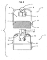
- FIG. 1 there is shown one form of a additive delivery system 1, which is not in accordance with the present invention but included for reference purposes, including an additive gel filter cap 2 which may be mounted onto, and removed from, a filter housing cap 3 where the filter housing cap 3 connects to a filter body housing (not shown) which includes a filter media (not shown) to form a complete filter, such as an oil filter.
- the filter housing cap 3 is shown with external threading 17 along its bottom edge where the filter housing body would have internal threading and the filter housing cap 3 would fasten to the filter housing body by spinning the filter housing cap 3 so the external threads 17 interface with the internal threads of the filter housing body.
- the filter housing cap 3 may have a filter media fastening device 18 located on the inside surface opposite of the surface that mounts onto the filter using device.
- This fastening device may be in the form of a circular clip that is used to secure a filter media insert (not shown) in the filter housing cap.
- the filter media insert may connect to the filter housing cap 3 by snapping onto the fastening device 18 or by similar means. This type of removable and replaceable filter media insert is commonly used in cartridge type filters.
- the filter housing cap 3 may also be part of a complete, single piece filter (not shown), where the filter housing cap cannot be separated from the rest of the filter housing, but is a single piece.
- the additive gel filter cap 2 may include a bolt head 5 on the crown of the additive gel filter cap 2, such as a hex bolt head, to allow for tools, such as wrenches, to interface with the gel filter cap 2.
- the filter housing cap 3 may also include a bolt head 12 on the crown of the filter housing cap, such as a hex bolt head.
- the additive gel filter cap 2 may include a bolt head socket 7, located on the inside surface of the additive gel filter cap 2 opposite of the end with the mounting surface for the filter using device, which rests on and interfaces with the filter housing cap 3 when the gel filter cap 2 is mounted on the filter housing cap 3. More specifically, the bolt head socket 7 of the additive gel filter cap 2, may interface with the bolt head 12 of the filter housing cap 3, creating an interface that allows the effect of tools on the bolt head of the additive gel filter cap 5 to be transferred to the bolt head 12 of the filter housing cap 3.
- the interface created by the additive gel filter cap's bolt head socket 7 allows the bolt head on the additive gel filter cap to be utilized in the same manner for the filter installation.
- the additive gel filter cap 2 contains the additive gel 4 in the interior void space 9 of the additive gel filter cap 2 between and around the bolt head socket 7 and the side wall 8 of the additive gel filter cap 2, as shown in Figure 1 .
- the additive gel 4 may be placed in the interior void space 9 prior to the additive gel filter cap 2 being mounted onto the filter housing cap 3.
- the additive gel 4 may be dispensed into the interior void space 9 whereby the components of the gel may be mixed within the space such that the gel formation/manufacturing occurs within the additive gel filter cap 2, or the additive gel 4 may be pre-formed into a shape or shapes that allows the gel to be inserted into the interior void space 9 of the additive gel filter cap 2.
- the additive gel 4 may be further contained in a gel container, package or gel cup (not shown) that may be inserted into the interior void space 9 of the additive gel filter cap 2.
- This gel cup may be removable, allowing the gel cup to be removed and replaced or refilled with gel, and placed in another additive gel filter cap 2 for additional use.
- a removable gel cup may also allow a used filter to be serviced, either after removal from the apparatus or device it is used with or while still connected to such an apparatus or device, by removing the additive gel filter cap 2 from the filter housing cap 3 and then removing the used gel cup and replacing it with a new gel cup with a new supply of additive gel 4.
- the gel cup may have openings of various sizes and shapes to allow for the contact of the fluid with the additive gel 4 present in the gel cup.
- the filter housing cap 3 may be a standard filter housing cap used with a filter housing body and filter media to form a conventional filter where modifications are made after the initial filter manufacturing in order to make the filter housing cap 3 compatible with the additive gel filter cap 2.
- the filter housing cap 3 may also be specially designed to work with an additive gel filter cap 2.
- the filter housing cap 3 may have one or more openings 13 located on the crown of the housing cap that allow for fluid, when a filter gel cap 2 is mounted onto the housing cap 3, to pass from the interior of the filter cap 14, through the openings 13 in the filter housing cap 3 and into the additive gel filter cap's interior void space 9, where the fluid comes into contact with the additive gel 4, and then passes through the openings 13 in the filter housing cap 3 and back into the interior of the filter cap 14 and the rest of the filter (not shown).
- the filter housing cap openings 13 may be one or more circular holes, as shown in Figure 1 , that allow for fluid to travel across the filter housing cap 3.
- the housing cap openings 13 may be of various sizes and shapes, including but not limited to circles, ovals, slits or mixtures thereof and may be arranged symmetrically or randomly on the filter housing cap 3.
- the openings 13 may also be so large as to effectively encompass the entire crown of the filter cap, leaving only the filter media insert support 18 and some means connecting the support 18 to a remaining rim of the filter housing cap 3 where the rim may include the housing cap's side exterior wall 16 and everything below it.
- the openings 13 may be arranged such that the axis passing through the center of the openings are parallel to the vertical axis of the filter housing cap 3.
- the openings 13 may be also be arranged such that the axis passing through the center of the openings are at an angle to the vertical axis of the filter housing cap 3.
- the openings 13 may be part of the filter design and fabrication or the openings 13 may be created after the filter is manufactured.
- the flow characteristic of the fluid as it contacts the additive gel 4 can be controlled and by modifying the orientation, size, shape, arrangement, location and combinations thereof of the openings 13 in the filter housing cap 3. Modifying one or more of these parameters related to the housing cap's openings 13 modifies the amount of surface area of the additive gel 4 contacted by the fluid passing through the additive gel filter cap 2; modifies the flow rate, flow direction, fluid pressure and other fluid flow characteristics of the fluid passing through the additive gel filter cap 2; or combinations thereof.
- This control of fluid flow characteristic allows for the additive delivery systems of the present invention to provide the desired additive gel component release rate while maintaining additive gel integrity in a wide variety of applications.
- the inner surface of the additive gel filter cap's side wall 8 may have an undercut, grade, reduction or similar geometric feature to create a flow path for the fluid around the additive gel 4 and/or to help keep the additive gel 4 secure and intact within the void space 9 of the additive gel filter cap 2.
- the additive gel filter cap 2 mounts onto the filter housing cap 3 whereby the additive gel filter cap 2 slides over filter housing cap 3 such that the bottom edge 11 of the side wall 8 of the additive gel filter cap 2 rests in an outer lip 15 that runs around the outside of the filter housing cap 3 below all of the openings 13 in the filter housing cap 3 and above the external threads 17 of the filter housing cap 3.
- the additive gel filter cap 2 may also include a seal cavity 10 which may be in the form of a annular space carved out of the lower inside surface of the side wall 8, forming a ring cavity that allows for the use of an o-ring or similar seal (not shown) in the seal cavity 10.
- the use of a seal in the seal cavity 10 can act to provide a seal between the additive gel filter cap 2 and the filter housing cap 3 where the seal in the seal cavity 10 contacts the filter housing cap exterior wall surface 16 when the additive gel filter cap 2 is mounted on the filter housing cap 3.
- the additive gel filter cap 2 may also be secured to the filter housing cap 3 by means of a bolt or similar fastening device.
- the bolt, or similar device may be placed through the center of the filter housing cap 3 through a hollow shaft 22 in the bolt head 12 on the crown of the housing cap 3. The bolt may then interface with threads on the walls of a similar shaft 6 in the center of the additive gel cap 2 thereby fastening the additive gel cap 2 onto the filter housing cap 3.
- Figure 1a shows a cross section diagram where the additive gel filter cap 2 and the filter housing cap 3 are in an assembled state, where the additive gel filter cap 2 is mounted on crown of the filter housing cap 3 and the arrows indicate the flow of the fluid being conditioned through the system.
- the filter body housing 19 and the filter media 20 are also shown.
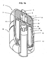
- Figure 1 b shows an exploded perspective view. The same labels are used to identify the various features of the embodiments shown in Figures 1 , 1a and 1b , unless otherwise noted. These embodiments are not according to the present invention and are included for reference purposes.
- the arrows indicate how the fluid from the device with which the filter is being used may flow within the filter, and more specifically how the fluid may flow within the filter housing cap 3, pass through the openings 13 in the filter housing cap 3 and into the additive gel filter cap 2 where the fluid comes into contact with the additive gel 4 and then passes back through the openings 13 in the filter housing cap 3, into the filter housing cap 3 and back to the device as filtered and conditioned fluid.
- the fluid flowing through the filter housing body 19 will pass through a filter element 20 which may be fabricated of any suitable filtering medium and will return the fluid to the device.
- the fluid as shown in Figure 1a , will also pass into the additive gel filter cap 2 where the fluid will come into contact with the additive gel 4 and then return to the filter housing cap 3 and the filter housing 19.
- This controlled flow of fluid across the additive gel 4 results in a controlled dissolution of the additive components of the additive gel 4 into the fluid while maintaining the physical integrity of the additive gel 4.
- the present invention allows gels of various formulations, including relatively soft gels that would otherwise: 1) release additive components too quickly, 2) release additive components at non-uniform rates, 3) completely dissolve before the end of a desired service cycle, 4) be broken up into gel fragments that would be carried by the fluid and potentially block device lines and orifices, or 5) combination thereof, to be used more effectively and in a wider range of applications without these issues.
- the additive delivery system 61 includes an additive gel filter cap which may be an integrated part of a filter housing cap.
- the filter housing cap and filter cap are in the form of an integrated part that contains the additive gel 78 and connects to the filter body housing (not shown) to form a filter.
- the integrated filter gel cap 61 of this embodiment may be a single piece that attaches to a filter body housing (not shown) just as a conventional filter housing cap would, utilizing interlocking threads or a similar fastening means.
- the integrated filter gel cap 61 of this embodiment may also be made up of two distinct parts, a lid 62 and a body 63 where the lid 62 may be removed from the body 63 to allow for better access to the annular space 74 that holds the additive gel 78.
- the lid 62 may have internal threading 69 on the inside of its bottom edge 70 used to connect it to the body 63.
- the body 63 may have external threading 72 on the outside of its upper edge 71 used to connect the body 63 to the lid 62.
- the lid 62 and the body 63 may be connected by placing the threads, 69 and 72, in contact with one another and spinning the lid 62 to engage the threads into one another.
- the integrated gel filter cap body 63 in Figure 2 is shown with external threading 76 along its bottom edge where the filter housing body (not shown) would have internal threading and the integrated gel filter cap body 63 would fasten to the filter housing body (not shown) by spinning the integrated gel filter cap body 63 so the external threads 76 interface with the internal threads of the filter housing body (not shown).
- the integrated gel filter cap lid 62 may have a filter media insert fastening device 67 similar to the media fastening device 18 in Figure 1 that allows filter media inserts to connect to the integrated gel filter cap lid 62.
- the embodiment of the present invention shown in Figure 2 may include a bolt head 65 on the crown of the integrated gel filter cap lid 62.
- the integrated gel filter cap 61 contains the additive gel 78 in the interior annular void space 74 of the integrated gel filter cap body 63 between the integrated gel filter cap body's outer wall 79 and its inner wall 75.
- This annular space 74 can be adjusted to hold various amounts of additive gel 78 based on the dimensions of the integrated gel filter cap 61 and specifically the integrated gel filter cap body 63.
- the additive gel 78 may be placed in the integrated gel filter cap's interior annular void space 74 in the same manners described above in regards to the embodiment shown in Figure 1 .
- the ability to remove the integrated gel filter cap lid 62 from the integrated gel filter cap body 63 allows for additional options of inserting the additive gel 78.
- the integrated gel filter cap body's interior wall 75 may have an inward curve that acts as a diverter edge or similar feature at its upper edge 73 as shown in Figure 2 .
- This diverter edge 73 acts to affect the flow characteristics present in a filter when it is fully assembled with the integrated filter gel cap 61.
- the geometry of the integrated gel filter cap's body's internal wall 75 and its diverter edge 73 can affect the amount of contact between the additive gel 78 and the fluid passing through the filter (not shown) as well as the flow rate, direction of flow relative to the additive gel 78 and pressure of the fluid during the contact.
- the integrated gel filter cap's body's internal wall 75 may also have one or more openings (not shown) located along the wall between the interior void space 77 that encloses the filter media insert (not shown) and the annular space 74 that contains the additive gel 78. These openings (not shown) may allow for fluid, when the integrated cap is assembled and used as a filter, to pass from the interior of the filter cap 77, through the openings in the integrated gel cap body's interior wall 75 and contact the additive gel 78 contained in the annular space 74.
- the fluid may contact the additive gel 78 at the openings and remain within the interior of the filter housing 77 or it may pass through the openings into the annular space 74, contacting the additive gel 78 during this period, and travel up to the interior wall's upper edge 73, where the fluid then returns to the interior space of the filter housing 77 and continues to pass through the filter.
- the integrated gel filter cap interior wall openings may be one or more circular holes, and may also be of various sizes and shapes, including but not limited to circles, ovals, slits or mixtures thereof and may be arranged symmetrically or randomly on the integrated gel filter cap's interior wall 75.
- the openings may be arranged such that the axis passing through the center of the openings are perpendicular to the plane of the interior wall 75.
- the openings may be also be arranged such that the axis passing through the center of the openings are at an angle to the plane of the interior wall 75.
- the flow characteristic of the fluid as it contacts the additive gel 78 can be controlled and by modifying the orientation, size, shape, arrangement, location and combinations thereof of the openings in the integrated gel filter cap body 63 and/or by modifying the geometry of the integrated gel filter cap's interior wall 75 and upper edge 73. Modifying one or more of these parameters modifies the amount of surface area of the additive gel 78 contacted by the fluid passing through the integrated gel filter cap 61; modifies the flow rate, flow direction, fluid pressure and other fluid flow characteristics of the fluid passing through the integrated gel filter cap 61; or combinations thereof.
- This control of fluid flow characteristic allows for the additive delivery systems of the present invention to provide the desired additive gel component release rate while maintaining additive gel integrity in a wide variety of applications.
- Figure 2a is a schematic longitudinal section view through one form of additive delivery system of the present invention in an assembled state which may also represent the present invention when the integrated filter gel cap lid and body are fixed and cannot be separated.
- the arrows indicate the flow of the fluid being conditioned through the system.
- the filter body housing 81 and the filter media 82 are also shown.
- Figure 2b shows a perspective view of the present invention. The same labels are used to identify the various features of the embodiments shown in Figures 2 , 2a and b, unless otherwise noted.
- Figure 2a shows a cross section diagram of the present invention where the integrated gel filter cap lid 62 and the integrated gel filter cap body 63 are in an assembled state, where the integrated gel filter cap lid 62 is mounted on crown of integrated gel filter cap body 63 and the arrows indicate the flow of the fluid being conditioned through the system.
- the filter body housing 81 and filter media 82 are also shown.
- the arrows indicate how the fluid from the device with which the filter is being used may flow within the filter, and more specifically within the integrated gel filter cap 61, as the fluid may pass through the filter housing interior 77, pass through the openings in the integrated gel filter cap's interior wall 75 and/or pass over the upper edge 73 of the interior wall 75, and into the annular space 74 containing the additive gel 78 where the fluid comes into contact with the additive gel 78 and then passes back through the openings in the integrated gel filter cap's interior wall 75 and/or passes over the upper edge 73 of the interior wall 75 and back to the filter housing space 77 and ultimately the connected device as filtered and conditioned fluid.
- the fluid flowing through the filter housing body 81 will pass through a filter element 82 which may be fabricated of any suitable filtering medium and will return the fluid to the device.
- the fluid as shown in Figure 2a , will also pass into the integrated gel filter cap's additive gel containing annular space 74 where the fluid will come into contact with the gel 78 and then return to the filter housing.
- This indirect flow of fluid across the additive gel 78 located in the annular space 74 will result in the controlled dissolution of the additive components of the additive gel 78 into the fluid while maintaining the physical integrity of the additive gel.
- the present invention allows gels of various formulations, including relatively soft gels that would otherwise release additive components too quickly, release additive components at non-uniform rates, completely dissolve before the end of a desired service cycle, be broken up into gel fragments that would be carried by the fluid and potentially block device lines and orifices, or combination thereof to be used more effectively and in a wider range of applications.
- the mixture is heated at 100C for 8 hours to form a gel.
- the filled additive gel filter cap is mounted onto a cartridge-style filter media insert and this assembly is fit into a cartridge-style filter housing, thus providing an additive delivery system of the present invention.
- the assembled filter cartridge and housing is placed on a dynamometer equipped with a PSA DV6 engine and run for 100 hours.
- oil analysis shows that an amount of viscosity modifier equivalent to and increase in 0.4 cSt has been released into the oil compared to a baseline in which a standard filter with no additive gel present.
Landscapes
- Chemical & Material Sciences (AREA)
- Chemical Kinetics & Catalysis (AREA)
- Organic Chemistry (AREA)
- General Chemical & Material Sciences (AREA)
- Oil, Petroleum & Natural Gas (AREA)
- Filtration Of Liquid (AREA)
- Lubrication Details And Ventilation Of Internal Combustion Engines (AREA)
Description
- The present invention relates to additive delivery systems for allowing a fluid, such as oil, to come into contact with an additive gel to cause one or more additive components in the gel to be slowly released into the fluid.
- Specially formulated slow-release additives that provide for the slow release of additives into a fluid such as oil to meet certain performance requirements of the fluid are generally known. In some, the additives are incorporated into thermoplastic polymers which slowly dissolve into the fluid. In others, the additives are incorporated into polymers which are oil-permeable at elevated temperatures. In still others, the additives are incorporated into particles which are fluid-insoluble but fluid-wettable. In still others, fluid soluble solid polymers are provided, with or without additional additives being incorporated into the polymers.
- Although these slow-release additives are capable of introducing additives in the fluid being conditioned, it has been discovered that additive gels can be used more effectively to provide for the slow release of additives into a fluid, such as lubricant additives into oil. In particular, it has been found that fluid-soluble additive gels slowly dissolve to their component additive parts when contacted by the fluid. Examples of such additive gels are disclosed in
U.S. Patent 6,843,916, filed July 16, 2002 ,U.S. Patent Applications Serial No. 10/603,644, filed June 25, 2003 10/603,894, filed June 25, 2003 10/603,517, filed June 25, 2003 -
Garvin et al, U.S. Patent 7,000,655 , discloses an additive delivery system which includes a container for the additive gel wherein the container has one or more openings to allow contact of the fluid with the gel to cause one or more additive components in the gel to be released into the fluid and the container is located in a housing with a means of mounting the housing between the filter and the filter mounting surface. -
Burrington et al, U.S. Patent 6,843,916 , discloses an oil filter comprising a housing, a filter for removing particulate matter from the oil passing through the filter, and oil-soluble lubricant additives inside the housing for slow release into the oil. - Although these additive delivery systems are capable of introducing additives into the fluid being conditioned, attaining a specific release rate of components while maintaining physical gel integrity is a critical feature for a practical controlled release gel system. Improper and/or non-uniform release rates may result in less than optimal performance of the fluid being conditioned and lack of physical gel integrity can result in particles of gel breaking off of the larger gel mass present in the controlled release system. These gel fragments are carried by the fluid and may plug filters and engine orifices, which may negatively impact the overall performance of the fluid-utilizing system or device.
- Some applications have unique fluid flow characteristics through the fluid system, filter and any additive delivery system present. These fluid flow characteristics, which include fluid pressure, temperature and flow rate, can interfere with an additive delivery system, resulting in undesired or non-optimal additive release rates and a loss in gel integrity, leading to problems discussed above. Diesel passenger cars in particular tend to have oil system flow characteristics that interfere with existing additive delivery systems.
- There is a need for additive delivery systems that allow for the desired contact of the fluid with these additive gels, to cause one or more components of the additives in the gels to be slowly released into the fluid, wherein the desired and/or uniform release rate of components is achieved while maintaining physical gel integrity. There is also a need for additive delivery systems that provides the desired controlled release of one or more additives in systems with various fluid flow characteristics, including those seen in the oil system of diesel passenger cars.
- The present invention involves delivery systems for supplying one or more additives to a fluid by allowing the contact of a fluid with an additive gel, causing one or more components of the additives in the gel to be slowly released into the fluid, wherein the desired and/or uniform release rate of components is achieved while maintaining physical gel integrity.
- In accordance with one aspect of the invention, the additive delivery system comprises an additive gel, a filter having a housing, and a fluid/gel chemistry exchange region located outside of the region of the filter housing that experiences the direct flow of the fluid where the fluid contacts the gel, said additive delivery system being defined in the appended
claim 1. - In accordance with another aspect of the invention, the exchange region of the system may allow for fluid/gel contacting comprising a) indirect fluid flow, b) direct fluid flow, or c) combinations thereof. The exchange region may be selected so as to control the release rate of additives from the additive gel into the fluid, to maintain a uniform release rate of additives, to maintain the physical integrity of the additive gel, or combinations thereof.
- In accordance with another aspect of the invention, the system may comprise a filter gel cap that contains the gel, wherein the filter gel cap is mountable and removable from the crown of the filter housing, wherein the filter housing has one or more openings on the crown of the filter that allow fluid to pass from the filter, contact the additive gel and return to the filter. The number, size, shape, orientation, location, pattern, or combinations thereof of the openings on the crown of the filter housing may be selected so as to control and maintain the desired additive gel component release rate and additive gel physical integrity.
- In accordance with the invention, the cap of the filter housing comprises an annular space along the outer wall of the filter cap housing, wherein the annular space is created by the outer wall of the filter cap housing body and an interior wall that forms a cylinder within the filter cap, wherein the interior wall connects to the outer wall on one end and is open on the other, and wherein the additive gel is placed within the annular space, whereby the fluid comes into contact with the additive gel in the filter by passing over the open end of the interior wall, contacting the additive gel in the annular space and passing back over the wall to the interior of the filter. The filter cap with the gel-containing annular space may have a mountable and removable lid that allows for direct access to the gel-containing annular space. The interior wall that forms the annular gel-containing space may contain one or more openings that allow fluid to pass from the filter housing into the annular space and contact the additive gel, and wherein the number, size, shape, orientation, location, pattern, or combinations thereof of the openings are utilized to control and maintain the desired additive gel component release rate and additive gel physical integrity.
- In accordance with another aspect of the invention, the filter may be a cartridge filter that is mounted inside a canister type housing that has inlet and outlet passages for permitting fluid to flow through the housing and around the cartridge.
- In accordance with another aspect of the invention, the delivery system may be used to condition the fluid in devices comprising internal combustion engines, natural gas engines, stationary engines, metal working coolant systems, industrial lubricated systems, oil or fuel filters, hydraulic systems, or transmission systems.
- In accordance with another aspect of the invention, the filter may be an oil filter and the fluid may be engine lubricating oil, and the device utilizing the filter may be a diesel passenger car engine.
- In accordance with another aspect of the invention, the system may be used as part of a method for releasing additives into a fluid comprising operating a device that utilizes a fluid.
- In accordance with another aspect of the invention, the system can be the filter cap that contains a fluid additive gel, which can be mounted onto a fluid filter in such a way as to allow a fluid to pass between the filter and the cap, wherein the filter cap, when mounted onto said filter, contains a fluid/gel chemistry exchange region located outside the interior region of the filter that experiences the direct flow of the fluid, where the fluid contacts the gel.
- The present invention may be more readily understood by reference to the following drawings in which:
-
Figure 1 is an exploded schematic longitudinal section view through one form of additive delivery system including a filter additive gel cap and filter housing cap, where the additive gel is present in the filter gel cap, where the filter gel cap fastens to the filter housing cap, such that when the assembly is used in an operating system, the assembly allows for the fluid that passes through the filter to pass through the openings in the filter housing cap and come into contact with the additive gel inside the filter gel cap. -
Figure 1a is a schematic longitudinal section view through one form of additive delivery system in an assembled state with fluid flow indicators. -
Figure 1b is a perspective view of one embodiment of the additive delivery system in an assembled state. -
Figure 2 is an exploded schematic longitudinal section view through one form of additive delivery system of the present invention including a combination filter additive gel cap and filter housing cap, where the additive gel is present in the combination filter additive gel cap and filter housing cap in an annular space, where the combination filter additive gel cap and filter housing cap comprises two parts, a body part and a lid part, where the lid can be removed to allow for more convenient insertion of the additive gel into the annular space, such that when the assembly is used in an operating system, the assembly allows for the fluid that passes through the filter to come into contact with the additive gel. -
Figure 2a is a schematic longitudinal section view through one form of additive delivery system of the present invention in an assembled state with fluid flow indicators. -
Figure 2b is a perspective view of one embodiment of the additive delivery system of the present invention in an assembled state. - The additive delivery systems of the present invention provide for the desired contact of a fluid being conditioned with an additive gel to cause one or more components of the additives in the gel to be slowly released into the fluid as described hereafter wherein the desired and/or uniform release rate of the one or more components is achieved while maintaining the physical integrity of the additive gel. The additive delivery systems of the present invention can be used to condition the fluid in any lubricated mechanical systems or devices including but not limited to those in internal combustion engines, such as, but not limited to, diesel passenger car engines, natural gas engines, stationary engines, metal working coolant systems, industrial lubricated systems, oil or fuel filters, hydraulic systems and transmission systems and the like. The additive delivery system of the present invention provides the desired release rate and maintains gel integrity under various fluid flow characteristics in the fluid system and filter. These fluid flow characteristics include, but are not limited to, fluid pressure, temperature and flow rate. This improved performance, across applications with varying fluid flow characteristics in the applications' fluid system and filters, is achieved through the design of the additive delivery systems of the present invention.
- In the additive delivery systems of the present invention the system comprises a fluid/gel chemistry exchange region where the gel and fluid come into contact with one another to allow for the release of additives from the additive gel into the fluid. The exchange region may allow for contact that subjects the additive gel to direct fluid flow, where direct fluid flow is fluid flow at the point of contact with the additive gel at the flow rate, direction, pressure, temperature, and the like, which is near or about the maximum value reached by the fluid in the filter for one or more of the parameters listed. The exchange region may allow for contact that subjects the additive gel to indirect fluid flow, where indirect fluid flow is fluid flow at the point of contact with the additive gel at a flow rate, direction, pressure, temperature, and the like, which is below the maximum value reached by the fluid in the filter for one or more of the parameters listed. Indirect flow regions may be created by placing the additive gel in a nearly enclosed region of the filter or outside the filter body as well as other means. The exchange region may also allow for combinations of these types of contact. This combination of exchange regions allows for the systems of the present invention to be customized to the additive release needs of the various applications, including applications with extreme or unusual flow characteristics in the filter.
- In one embodiment the additive delivery systems of the present invention contain the additive gel within a gel filter cap which attaches to the outer body of a filter whereby the additive gel is located outside of the filter housing and is not located in the direct flow areas of the fluid that passes through the filter. In one embodiment of the present invention, the filters used in the additive delivery systems of the present invention may be cartridge filters and the fluid may be lubricating oil.
- Examples of additive gels which may be used with the present invention are disclosed in
U.S. Patent 6,843,916, filed July 16, 2002 ,U.S. Patent Applications Serial No. 10/603,644, filed June 25, 2003 10/603,894, filed June 25, 2003 10/603,517, filed June 25, 2003 - Referring now in detail to the drawings, wherein the same reference numbers are used to designate like parts, and initially to
Figure 1 , there is shown one form of aadditive delivery system 1, which is not in accordance with the present invention but included for reference purposes, including an additivegel filter cap 2 which may be mounted onto, and removed from, afilter housing cap 3 where thefilter housing cap 3 connects to a filter body housing (not shown) which includes a filter media (not shown) to form a complete filter, such as an oil filter. Thefilter housing cap 3 is shown withexternal threading 17 along its bottom edge where the filter housing body would have internal threading and thefilter housing cap 3 would fasten to the filter housing body by spinning thefilter housing cap 3 so theexternal threads 17 interface with the internal threads of the filter housing body. Thefilter housing cap 3 may have a filtermedia fastening device 18 located on the inside surface opposite of the surface that mounts onto the filter using device. This fastening device may be in the form of a circular clip that is used to secure a filter media insert (not shown) in the filter housing cap. The filter media insert may connect to thefilter housing cap 3 by snapping onto thefastening device 18 or by similar means. This type of removable and replaceable filter media insert is commonly used in cartridge type filters. Thefilter housing cap 3 may also be part of a complete, single piece filter (not shown), where the filter housing cap cannot be separated from the rest of the filter housing, but is a single piece. - The additive
gel filter cap 2 may include abolt head 5 on the crown of the additivegel filter cap 2, such as a hex bolt head, to allow for tools, such as wrenches, to interface with thegel filter cap 2. Thefilter housing cap 3 may also include abolt head 12 on the crown of the filter housing cap, such as a hex bolt head. - The additive
gel filter cap 2 may include abolt head socket 7, located on the inside surface of the additivegel filter cap 2 opposite of the end with the mounting surface for the filter using device, which rests on and interfaces with thefilter housing cap 3 when thegel filter cap 2 is mounted on thefilter housing cap 3. More specifically, thebolt head socket 7 of the additivegel filter cap 2, may interface with thebolt head 12 of thefilter housing cap 3, creating an interface that allows the effect of tools on the bolt head of the additivegel filter cap 5 to be transferred to thebolt head 12 of thefilter housing cap 3. For example, where the bolt head on the crown of a filter is utilized to install the filter onto a larger device, such as an internal combustion engine, the interface created by the additive gel filter cap'sbolt head socket 7 allows the bolt head on the additive gel filter cap to be utilized in the same manner for the filter installation. - The additive
gel filter cap 2 contains theadditive gel 4 in the interiorvoid space 9 of the additivegel filter cap 2 between and around thebolt head socket 7 and theside wall 8 of the additivegel filter cap 2, as shown inFigure 1 . Theadditive gel 4 may be placed in the interiorvoid space 9 prior to the additivegel filter cap 2 being mounted onto thefilter housing cap 3. Theadditive gel 4 may be dispensed into the interiorvoid space 9 whereby the components of the gel may be mixed within the space such that the gel formation/manufacturing occurs within the additivegel filter cap 2, or theadditive gel 4 may be pre-formed into a shape or shapes that allows the gel to be inserted into the interiorvoid space 9 of the additivegel filter cap 2. Theadditive gel 4 may be further contained in a gel container, package or gel cup (not shown) that may be inserted into the interiorvoid space 9 of the additivegel filter cap 2. This gel cup may be removable, allowing the gel cup to be removed and replaced or refilled with gel, and placed in another additivegel filter cap 2 for additional use. A removable gel cup may also allow a used filter to be serviced, either after removal from the apparatus or device it is used with or while still connected to such an apparatus or device, by removing the additivegel filter cap 2 from thefilter housing cap 3 and then removing the used gel cup and replacing it with a new gel cup with a new supply ofadditive gel 4. The gel cup may have openings of various sizes and shapes to allow for the contact of the fluid with theadditive gel 4 present in the gel cup. - The
filter housing cap 3 may be a standard filter housing cap used with a filter housing body and filter media to form a conventional filter where modifications are made after the initial filter manufacturing in order to make thefilter housing cap 3 compatible with the additivegel filter cap 2. Thefilter housing cap 3 may also be specially designed to work with an additivegel filter cap 2. Thefilter housing cap 3 may have one ormore openings 13 located on the crown of the housing cap that allow for fluid, when afilter gel cap 2 is mounted onto thehousing cap 3, to pass from the interior of thefilter cap 14, through theopenings 13 in thefilter housing cap 3 and into the additive gel filter cap's interiorvoid space 9, where the fluid comes into contact with theadditive gel 4, and then passes through theopenings 13 in thefilter housing cap 3 and back into the interior of thefilter cap 14 and the rest of the filter (not shown). - The filter
housing cap openings 13 may be one or more circular holes, as shown inFigure 1 , that allow for fluid to travel across thefilter housing cap 3. Thehousing cap openings 13 may be of various sizes and shapes, including but not limited to circles, ovals, slits or mixtures thereof and may be arranged symmetrically or randomly on thefilter housing cap 3. Theopenings 13 may also be so large as to effectively encompass the entire crown of the filter cap, leaving only the filter media insertsupport 18 and some means connecting thesupport 18 to a remaining rim of thefilter housing cap 3 where the rim may include the housing cap's sideexterior wall 16 and everything below it. Theopenings 13 may be arranged such that the axis passing through the center of the openings are parallel to the vertical axis of thefilter housing cap 3. Theopenings 13 may be also be arranged such that the axis passing through the center of the openings are at an angle to the vertical axis of thefilter housing cap 3. Theopenings 13 may be part of the filter design and fabrication or theopenings 13 may be created after the filter is manufactured. - The flow characteristic of the fluid as it contacts the
additive gel 4 can be controlled and by modifying the orientation, size, shape, arrangement, location and combinations thereof of theopenings 13 in thefilter housing cap 3. Modifying one or more of these parameters related to the housing cap'sopenings 13 modifies the amount of surface area of theadditive gel 4 contacted by the fluid passing through the additivegel filter cap 2; modifies the flow rate, flow direction, fluid pressure and other fluid flow characteristics of the fluid passing through the additivegel filter cap 2; or combinations thereof. This control of fluid flow characteristic allows for the additive delivery systems of the present invention to provide the desired additive gel component release rate while maintaining additive gel integrity in a wide variety of applications. - In addition, the inner surface of the additive gel filter cap's
side wall 8 may have an undercut, grade, reduction or similar geometric feature to create a flow path for the fluid around theadditive gel 4 and/or to help keep theadditive gel 4 secure and intact within thevoid space 9 of the additivegel filter cap 2. - The additive
gel filter cap 2 mounts onto thefilter housing cap 3 whereby the additivegel filter cap 2 slides overfilter housing cap 3 such that thebottom edge 11 of theside wall 8 of the additivegel filter cap 2 rests in anouter lip 15 that runs around the outside of thefilter housing cap 3 below all of theopenings 13 in thefilter housing cap 3 and above theexternal threads 17 of thefilter housing cap 3. The additivegel filter cap 2 may also include aseal cavity 10 which may be in the form of a annular space carved out of the lower inside surface of theside wall 8, forming a ring cavity that allows for the use of an o-ring or similar seal (not shown) in theseal cavity 10. The use of a seal in theseal cavity 10 can act to provide a seal between the additivegel filter cap 2 and thefilter housing cap 3 where the seal in theseal cavity 10 contacts the filter housing capexterior wall surface 16 when the additivegel filter cap 2 is mounted on thefilter housing cap 3. - The additive
gel filter cap 2 may also be secured to thefilter housing cap 3 by means of a bolt or similar fastening device. The bolt, or similar device, may be placed through the center of thefilter housing cap 3 through ahollow shaft 22 in thebolt head 12 on the crown of thehousing cap 3. The bolt may then interface with threads on the walls of asimilar shaft 6 in the center of theadditive gel cap 2 thereby fastening theadditive gel cap 2 onto thefilter housing cap 3. -
Figure 1a shows a cross section diagram where the additivegel filter cap 2 and thefilter housing cap 3 are in an assembled state, where the additivegel filter cap 2 is mounted on crown of thefilter housing cap 3 and the arrows indicate the flow of the fluid being conditioned through the system. Thefilter body housing 19 and thefilter media 20 are also shown.Figure 1 b shows an exploded perspective view. The same labels are used to identify the various features of the embodiments shown inFigures 1 ,1a and1b , unless otherwise noted. These embodiments are not according to the present invention and are included for reference purposes. - In
Figure 1a the arrows indicate how the fluid from the device with which the filter is being used may flow within the filter, and more specifically how the fluid may flow within thefilter housing cap 3, pass through theopenings 13 in thefilter housing cap 3 and into the additivegel filter cap 2 where the fluid comes into contact with theadditive gel 4 and then passes back through theopenings 13 in thefilter housing cap 3, into thefilter housing cap 3 and back to the device as filtered and conditioned fluid. - The fluid flowing through the
filter housing body 19 will pass through afilter element 20 which may be fabricated of any suitable filtering medium and will return the fluid to the device. The fluid, as shown inFigure 1a , will also pass into the additivegel filter cap 2 where the fluid will come into contact with theadditive gel 4 and then return to thefilter housing cap 3 and thefilter housing 19. This controlled flow of fluid across theadditive gel 4 results in a controlled dissolution of the additive components of theadditive gel 4 into the fluid while maintaining the physical integrity of theadditive gel 4. The present invention allows gels of various formulations, including relatively soft gels that would otherwise: 1) release additive components too quickly, 2) release additive components at non-uniform rates, 3) completely dissolve before the end of a desired service cycle, 4) be broken up into gel fragments that would be carried by the fluid and potentially block device lines and orifices, or 5) combination thereof, to be used more effectively and in a wider range of applications without these issues. - An embodiment of the present invention is shown in
Figure 2 , where theadditive delivery system 61 includes an additive gel filter cap which may be an integrated part of a filter housing cap. In this embodiment, the filter housing cap and filter cap are in the form of an integrated part that contains theadditive gel 78 and connects to the filter body housing (not shown) to form a filter. - The integrated
filter gel cap 61 of this embodiment may be a single piece that attaches to a filter body housing (not shown) just as a conventional filter housing cap would, utilizing interlocking threads or a similar fastening means. The integratedfilter gel cap 61 of this embodiment may also be made up of two distinct parts, alid 62 and abody 63 where thelid 62 may be removed from thebody 63 to allow for better access to theannular space 74 that holds theadditive gel 78. Thelid 62 may have internal threading 69 on the inside of itsbottom edge 70 used to connect it to thebody 63. Thebody 63 may have external threading 72 on the outside of itsupper edge 71 used to connect thebody 63 to thelid 62. Thelid 62 and thebody 63 may be connected by placing the threads, 69 and 72, in contact with one another and spinning thelid 62 to engage the threads into one another. - The integrated gel
filter cap body 63 inFigure 2 is shown with external threading 76 along its bottom edge where the filter housing body (not shown) would have internal threading and the integrated gelfilter cap body 63 would fasten to the filter housing body (not shown) by spinning the integrated gelfilter cap body 63 so theexternal threads 76 interface with the internal threads of the filter housing body (not shown). - The integrated gel
filter cap lid 62 may have a filter mediainsert fastening device 67 similar to themedia fastening device 18 inFigure 1 that allows filter media inserts to connect to the integrated gelfilter cap lid 62. - Similar to the embodiment of the present invention shown in
Figure 1 , the embodiment of the present invention shown inFigure 2 may include abolt head 65 on the crown of the integrated gelfilter cap lid 62. - The integrated
gel filter cap 61 contains theadditive gel 78 in the interior annularvoid space 74 of the integrated gelfilter cap body 63 between the integrated gel filter cap body'souter wall 79 and itsinner wall 75. Thisannular space 74 can be adjusted to hold various amounts ofadditive gel 78 based on the dimensions of the integratedgel filter cap 61 and specifically the integrated gelfilter cap body 63. Theadditive gel 78 may be placed in the integrated gel filter cap's interior annularvoid space 74 in the same manners described above in regards to the embodiment shown inFigure 1 . The ability to remove the integrated gelfilter cap lid 62 from the integrated gelfilter cap body 63 allows for additional options of inserting theadditive gel 78. - The integrated gel filter cap body's
interior wall 75 may have an inward curve that acts as a diverter edge or similar feature at itsupper edge 73 as shown inFigure 2 . Thisdiverter edge 73 acts to affect the flow characteristics present in a filter when it is fully assembled with the integratedfilter gel cap 61. Specifically, the geometry of the integrated gel filter cap's body'sinternal wall 75 and itsdiverter edge 73 can affect the amount of contact between theadditive gel 78 and the fluid passing through the filter (not shown) as well as the flow rate, direction of flow relative to theadditive gel 78 and pressure of the fluid during the contact. The integrated gel filter cap's body'sinternal wall 75 may also have one or more openings (not shown) located along the wall between theinterior void space 77 that encloses the filter media insert (not shown) and theannular space 74 that contains theadditive gel 78. These openings (not shown) may allow for fluid, when the integrated cap is assembled and used as a filter, to pass from the interior of thefilter cap 77, through the openings in the integrated gel cap body'sinterior wall 75 and contact theadditive gel 78 contained in theannular space 74. The fluid may contact theadditive gel 78 at the openings and remain within the interior of thefilter housing 77 or it may pass through the openings into theannular space 74, contacting theadditive gel 78 during this period, and travel up to the interior wall'supper edge 73, where the fluid then returns to the interior space of thefilter housing 77 and continues to pass through the filter. - The integrated gel filter cap interior wall openings (not shown) may be one or more circular holes, and may also be of various sizes and shapes, including but not limited to circles, ovals, slits or mixtures thereof and may be arranged symmetrically or randomly on the integrated gel filter cap's
interior wall 75. The openings may be arranged such that the axis passing through the center of the openings are perpendicular to the plane of theinterior wall 75. The openings may be also be arranged such that the axis passing through the center of the openings are at an angle to the plane of theinterior wall 75. - The flow characteristic of the fluid as it contacts the
additive gel 78 can be controlled and by modifying the orientation, size, shape, arrangement, location and combinations thereof of the openings in the integrated gelfilter cap body 63 and/or by modifying the geometry of the integrated gel filter cap'sinterior wall 75 andupper edge 73. Modifying one or more of these parameters modifies the amount of surface area of theadditive gel 78 contacted by the fluid passing through the integratedgel filter cap 61; modifies the flow rate, flow direction, fluid pressure and other fluid flow characteristics of the fluid passing through the integratedgel filter cap 61; or combinations thereof. This control of fluid flow characteristic allows for the additive delivery systems of the present invention to provide the desired additive gel component release rate while maintaining additive gel integrity in a wide variety of applications. -
Figure 2a is a schematic longitudinal section view through one form of additive delivery system of the present invention in an assembled state which may also represent the present invention when the integrated filter gel cap lid and body are fixed and cannot be separated. The arrows indicate the flow of the fluid being conditioned through the system. Thefilter body housing 81 and thefilter media 82 are also shown.Figure 2b shows a perspective view of the present invention. The same labels are used to identify the various features of the embodiments shown inFigures 2 ,2a and b, unless otherwise noted. -
Figure 2a shows a cross section diagram of the present invention where the integrated gelfilter cap lid 62 and the integrated gelfilter cap body 63 are in an assembled state, where the integrated gelfilter cap lid 62 is mounted on crown of integrated gelfilter cap body 63 and the arrows indicate the flow of the fluid being conditioned through the system. Thefilter body housing 81 andfilter media 82 are also shown. - In
Figure 2a the arrows indicate how the fluid from the device with which the filter is being used may flow within the filter, and more specifically within the integratedgel filter cap 61, as the fluid may pass through thefilter housing interior 77, pass through the openings in the integrated gel filter cap'sinterior wall 75 and/or pass over theupper edge 73 of theinterior wall 75, and into theannular space 74 containing theadditive gel 78 where the fluid comes into contact with theadditive gel 78 and then passes back through the openings in the integrated gel filter cap'sinterior wall 75 and/or passes over theupper edge 73 of theinterior wall 75 and back to thefilter housing space 77 and ultimately the connected device as filtered and conditioned fluid. - The fluid flowing through the
filter housing body 81 will pass through afilter element 82 which may be fabricated of any suitable filtering medium and will return the fluid to the device. The fluid, as shown inFigure 2a , will also pass into the integrated gel filter cap's additive gel containingannular space 74 where the fluid will come into contact with thegel 78 and then return to the filter housing. This indirect flow of fluid across theadditive gel 78 located in theannular space 74 will result in the controlled dissolution of the additive components of theadditive gel 78 into the fluid while maintaining the physical integrity of the additive gel. The present invention allows gels of various formulations, including relatively soft gels that would otherwise release additive components too quickly, release additive components at non-uniform rates, completely dissolve before the end of a desired service cycle, be broken up into gel fragments that would be carried by the fluid and potentially block device lines and orifices, or combination thereof to be used more effectively and in a wider range of applications. - The identifying features of the embodiments shown in
Figure 2a are similar to those described inFigure 2 and are identified by the same labels. - Into a container of the style shown in
Figure 2 andFigure 2a , two equally spaced rows of 6 holes in each row, each hole measuring 5 mm in diameter, are drilled into the annular space wall. Into the annular space is placed a mixture of the following composition:Table 1 - Composition ofAdditive Gel Percent by Weight Component 13.2% Olefin copolymer viscosity modifier 47.8% diluent mineral oil 2.4% ashless polyisobutylene succinic anhydride dispersant maleic anhydride styrene 9.6% copolymer, partially esterified 100.0% TOTAL - The mixture is heated at 100C for 8 hours to form a gel. The filled additive gel filter cap is mounted onto a cartridge-style filter media insert and this assembly is fit into a cartridge-style filter housing, thus providing an additive delivery system of the present invention.
- The assembled filter cartridge and housing is placed on a dynamometer equipped with a PSA DV6 engine and run for 100 hours. At the end of the test, oil analysis shows that an amount of viscosity modifier equivalent to and increase in 0.4 cSt has been released into the oil compared to a baseline in which a standard filter with no additive gel present.
Claims (12)
- A delivery system for supplying one or more additives to a fluid comprising an additive gel (78), a filter comprising a housing, and a fluid/gel chemistry exchange region located outside of the region of the filter housing that experiences the direct flow of the fluid where the fluid contacts the gel;
wherein the filter housing comprises a body (81) and a cap (63), where the cap comprises an inner wall (75) and an outer wall (79), wherein the inner wall forms a cylinder within the filter cap that connects to the outer wall at one end of the cap and is open at the other end of the cap, and wherein the inner wall and outer wall form an annular space (74) along the outer wall of
the cap and wherein the additive gel is placed within the annular space; and wherein the cap fastens to the body of the filter forming the filter housing such that the cap is located on the crown of the filter housing at the opposite end of the filter that mounts onto a filter using device. - The system of claim 1 wherein
the filter gel cap is mountable and removable from the crown of the filter housing, wherein the filter housing has one or more openings on the crown of the filter that allow fluid to pass from the filter, contact the additive gel and return to the filter; wherein the number, size, shape, orientation, location, pattern, or combinations thereof of the openings on the crown of the filter housing are selected so as to control and maintain the desired additive gel component release rate and additive gel physical integrity. - The system of claim 1 wherein the inner wall that forms the annular gel-containing space contains one or more openings that allow fluid to pass from the filter housing into the annular space and contact the additive gel, and wherein the number, size, shape, orientation, location, pattern, or combinations thereof of the openings are utilized to control and maintain the desired additive gel component release rate and additive gel physical integrity.
- The system of claim 3 wherein the inner wall that forms the annular gel-containing space forms an upper lip that acts as a diverter edge, wherein the diverter edge is designed to affect the fluid flow around the edge and so into the gel-containing annular space.
- The system of claim 1 wherein the additive gel is contained within a gel cup, wherein one or more gel cups may be inserted into and removed from the system, the gel cup having one or more openings to allow contact of the fluid that passes through the filter with the gel.
- The system of claim 3 wherein at least some of the openings in the interior wall of the annular space are unobstructed by the additive gel inside the space so as to allow some of the fluid to enter the annular space through the openings and dissolve one or more additive components in the gel.
- The system of claim 3 further comprising a fluid flow diverter edge (73) at the open end of the inner wall that forms the gel-containing annular space, wherein the diverter edge acts to divert the flow of the fluid passing through the filter and near the opening of the annular gel-containing space, providing control over the gel/fluid chemistry exchange region.
- The system of claim 1 wherein the filter is a cartridge filter that is mounted inside a canister type housing that has inlet and outlet passages for permitting fluid to flow through the housing and around the cartridge; and wherein the delivery system is used to condition the fluid in devices comprising internal combustion engines, natural gas engines, stationary engines, metal working coolant systems, industrial lubricated systems, oil or fuel filters, hydraulic systems, or transmission systems.
- The system of claim 1 wherein the filter is an oil filter and the fluid is engine lubricating oil.
- The system of claim 9 wherein the device utilizing the filter is a diesel passenger car engine.
- A method for releasing additives into a fluid comprising operating a device that utilizes a fluid, wherein the device utilizes the system of claim 1.
- A filter cap that contains a fluid additive gel which can be mounted onto a fluid filter in such a way as to allow a fluid to pass between the fluid filter and the filter cap, wherein the filter cap, when mounted onto said filter, contains a fluid/gel chemistry exchange region located outside of the region of the interior of the filter that experiences the direct flow of the fluid, where the fluid contacts the gel and wherein the cap comprises an inner wall and an outer wall, wherein the inner wall forms a cylinder within the filter cap that connects to the outer wall at one end of the cap and is open at the other end of the cap; and wherein the inner wall and outer wall form an annular space along the outer wall of the cap and wherein the additive gel is placed within the annular space; and wherein the cap fastens to the body of the filter forming the filter housing such that the cap is located on the crown of the filter housing at the opposite end of the filter that mounts onto a filter using device.
Applications Claiming Priority (2)
| Application Number | Priority Date | Filing Date | Title |
|---|---|---|---|
| US11/875,022 US20090101561A1 (en) | 2007-10-19 | 2007-10-19 | Filter Cap Additive Delivery System |
| PCT/US2008/079819 WO2009052097A1 (en) | 2007-10-19 | 2008-10-14 | Filter cap additive delivery system |
Publications (2)
| Publication Number | Publication Date |
|---|---|
| EP2203234A1 EP2203234A1 (en) | 2010-07-07 |
| EP2203234B1 true EP2203234B1 (en) | 2015-03-11 |
Family
ID=40229910
Family Applications (1)
| Application Number | Title | Priority Date | Filing Date |
|---|---|---|---|
| EP08839331.9A Not-in-force EP2203234B1 (en) | 2007-10-19 | 2008-10-14 | Filter cap additive delivery system |
Country Status (8)
| Country | Link |
|---|---|
| US (2) | US20090101561A1 (en) |
| EP (1) | EP2203234B1 (en) |
| KR (1) | KR20100075647A (en) |
| CN (1) | CN101827637B (en) |
| BR (1) | BRPI0818553A2 (en) |
| CA (1) | CA2702836A1 (en) |
| ES (1) | ES2537310T3 (en) |
| WO (1) | WO2009052097A1 (en) |
Families Citing this family (1)
| Publication number | Priority date | Publication date | Assignee | Title |
|---|---|---|---|---|
| CN113304517A (en) * | 2021-05-25 | 2021-08-27 | 刘万斌 | Easy-to-detach oil filter |
Family Cites Families (41)
| Publication number | Priority date | Publication date | Assignee | Title |
|---|---|---|---|---|
| FR779197A (en) | 1937-12-31 | 1935-03-30 | Bosch Robert | Filter for liquids, especially for lubricants and fuels |
| GB589079A (en) | 1944-06-13 | 1947-06-11 | Tecalemit Ltd | Impregnated oil filters |
| US3749247A (en) | 1970-09-21 | 1973-07-31 | Phillips Petroleum Co | Addition of oxidation inhibitor to lubricating oil |
| US4014794A (en) | 1974-03-11 | 1977-03-29 | E. I. Du Pont De Nemours And Company | Oil filter adapter |
| US4075097A (en) | 1975-04-01 | 1978-02-21 | Monroe Auto Equipment Company | Oil filter with oil improving dissolving body |
| US4144166A (en) | 1977-03-24 | 1979-03-13 | Atlantic Richfield Company | Compositions, apparatus and methods useful for releasing solid lubricating oil additive |
| US4144169A (en) | 1977-06-06 | 1979-03-13 | Monroe Auto Equipment Company | Filter unit |
| IT1165502B (en) | 1980-01-11 | 1987-04-22 | Tecnocar Spa | FILTER FOR INTERNAL COMBUSTION ENGINE LUBRICANTS PARTICULARLY FOR VEHICLES |
| IT1192015B (en) | 1986-06-27 | 1988-03-31 | Tecnocar Spa | FILTER FOR INTERNAL COMBUSTION ENGINE LUBRICANTS WITH RESERVE OF ADDITIVES |
| US5069799A (en) | 1989-09-07 | 1991-12-03 | Exxon Research & Engineering Company | Method for rejuvenating lubricating oils |
| US5209842A (en) | 1990-08-08 | 1993-05-11 | Moor Stephen E | Oil enhancing multifunction filter |
| DE4201559A1 (en) | 1992-01-22 | 1993-07-29 | Schwaebische Huettenwerke Gmbh | MATERIAL FOR FILTERS, IN PARTICULAR OIL, GASOLINE OR DIESEL FILTERS OF MOTOR VEHICLES |
| US5374354A (en) | 1992-09-24 | 1994-12-20 | Sundstrand Corporation | Method of increasing service life of oil and a filter in an integrated drive generator or constant speed drive and improved oil filter for use therein |
| US5552040A (en) | 1992-09-24 | 1996-09-03 | Sundstrand Corporation | Method of increasing service life of oil and a filter for use therewith |
| US5327861A (en) | 1993-07-26 | 1994-07-12 | Navistar International Transportation Corp. | Automatic oil additive injector |
| US5342519A (en) * | 1993-07-30 | 1994-08-30 | Donaldson Company, Inc. | Fluid filter cartridge with replaceable filter element |
| US5591330A (en) | 1994-05-25 | 1997-01-07 | T/F Purifiner, Inc. | Oil filter containing an oil soluble thermoplastic additive material therein |
| US5725031A (en) | 1996-08-01 | 1998-03-10 | Alliedsignal Inc. | Method for introducing PTFE into a spin-on oil filter |
| US5718258A (en) | 1996-10-22 | 1998-02-17 | T/F Purifiner, Inc. | Releasing additives into engine oil |
| US5843284A (en) | 1997-05-02 | 1998-12-01 | Paul J. T. Waters | Two-stage oil bypass filter device |
| US6238554B1 (en) | 1999-06-16 | 2001-05-29 | Fleetguard, Inc. | Fuel filter including slow release additive |
| US6860241B2 (en) * | 1999-06-16 | 2005-03-01 | Dober Chemical Corp. | Fuel filter including slow release additive |
| US6495495B1 (en) | 1999-08-20 | 2002-12-17 | The Lubrizol Corporation | Filterability improver |
| DE19948658A1 (en) | 1999-10-08 | 2001-04-12 | Mann & Hummel Filter | Oil circuit for a work machine |
| US7018531B2 (en) | 2001-05-30 | 2006-03-28 | Honeywell International Inc. | Additive dispensing cartridge for an oil filter, and oil filter incorporating same |
| US7291264B2 (en) | 2000-05-08 | 2007-11-06 | Honeywell International, Inc. | Staged oil filter incorporating additive-releasing particles |
| US6379564B1 (en) | 2000-05-08 | 2002-04-30 | Ronald Paul Rohrbach | Multi-stage fluid filter, and methods of making and using same |
| US7182863B2 (en) * | 2000-05-08 | 2007-02-27 | Honeywell International, Inc. | Additive dispersing filter and method of making |
| US6623636B2 (en) * | 2000-05-08 | 2003-09-23 | Honeywell International Inc. | Staged oil filter incorporating timed release oil conditioner |
| DE10103345A1 (en) | 2001-01-25 | 2002-08-14 | Hermann Trabold | Filter pack for filtering liquid or gaseous media |
| US6505597B2 (en) | 2001-05-30 | 2003-01-14 | Honeywell International Inc. | Cleansing oil filter containing quick-release liquid antioxidant/additive solution, and method of using same to convert an engine from petroleum-based oil to botanically-based oil |
| WO2003018163A1 (en) * | 2001-08-24 | 2003-03-06 | Dober Chemical Corporation | Controlled release of additives in fluid systems |
| DE10242850A1 (en) | 2002-01-25 | 2003-07-31 | Hermann Trabold | Filter packing used for filtering oils used in drive motors and hydraulic devices comprises porous material with additive |
| US6843916B2 (en) | 2002-07-16 | 2005-01-18 | The Lubrizol Corporation | Slow release lubricant additives gel |
| US6793814B2 (en) | 2002-10-08 | 2004-09-21 | M-I L.L.C. | Clarifying tank |
| US7000655B2 (en) * | 2004-01-09 | 2006-02-21 | The Lubrizol Corporation | Fluid additive delivery systems |
| DE102004001983B4 (en) * | 2004-01-13 | 2009-02-12 | Mann + Hummel Gmbh | additive filters |
| RU2007100341A (en) | 2004-06-11 | 2008-07-20 | Хонейвелл Интернэшнл Инк. (Us) | COMPOSITION OF CAR ADDITION AND METHOD FOR PRODUCING IT |
| US8016125B2 (en) | 2005-05-20 | 2011-09-13 | Lutek, Llc | Materials, filters, and systems for immobilizing combustion by-products and controlling lubricant viscosity |
| US20070004601A1 (en) | 2005-07-01 | 2007-01-04 | Mathur Naresh C | Additive composition |
| US20070049505A1 (en) * | 2005-08-24 | 2007-03-01 | Baker Mark R | Controlled release of additive gel(s) for functional fluids |
-
2007
- 2007-10-19 US US11/875,022 patent/US20090101561A1/en not_active Abandoned
-
2008
- 2008-10-14 EP EP08839331.9A patent/EP2203234B1/en not_active Not-in-force
- 2008-10-14 KR KR1020107010900A patent/KR20100075647A/en not_active Withdrawn
- 2008-10-14 CA CA2702836A patent/CA2702836A1/en not_active Abandoned
- 2008-10-14 WO PCT/US2008/079819 patent/WO2009052097A1/en not_active Ceased
- 2008-10-14 CN CN2008801122051A patent/CN101827637B/en not_active Expired - Fee Related
- 2008-10-14 ES ES08839331.9T patent/ES2537310T3/en active Active
- 2008-10-14 BR BRPI0818553-0A patent/BRPI0818553A2/en not_active IP Right Cessation
-
2010
- 2010-10-11 US US12/901,674 patent/US8293119B2/en not_active Expired - Fee Related
Also Published As
| Publication number | Publication date |
|---|---|
| US20110036784A1 (en) | 2011-02-17 |
| WO2009052097A9 (en) | 2009-08-13 |
| CN101827637B (en) | 2012-11-28 |
| EP2203234A1 (en) | 2010-07-07 |
| CA2702836A1 (en) | 2009-04-23 |
| BRPI0818553A2 (en) | 2015-06-16 |
| CN101827637A (en) | 2010-09-08 |
| WO2009052097A1 (en) | 2009-04-23 |
| US20090101561A1 (en) | 2009-04-23 |
| KR20100075647A (en) | 2010-07-02 |
| ES2537310T3 (en) | 2015-06-05 |
| US8293119B2 (en) | 2012-10-23 |
Similar Documents
| Publication | Publication Date | Title |
|---|---|---|
| EP1587599B1 (en) | Additive dispensing cartridge for an oil filter and oil filter incorporating same | |
| RU2636592C2 (en) | Removable container for fluid | |
| US8021558B2 (en) | Additive dispersing filter and method of making | |
| US5443138A (en) | Universal sandwich adapter and threaded nipple for attaching same | |
| WO2002096534A1 (en) | Staged oil filter incorporating additive-releasing particles | |
| WO1998050128A1 (en) | Two-stage oil bypass filter device | |
| US20110011795A1 (en) | Fluid pressure driven centrifuge apparatus | |
| WO2016122823A1 (en) | Flow cap and method for directing a fluid through a filter | |
| EP1701782B1 (en) | Fluid additive delivery systems | |
| US8293119B2 (en) | Filter cap additive delivery system | |
| CN108290094A (en) | Cartridges and filters for oil filters in cars | |
| CN104024587A (en) | Lubricant oil filter with continuous release additive vessel | |
| CA2153737A1 (en) | Rebuildable spin-on filters | |
| US7588691B2 (en) | Additive dispersing filter and method of making | |
| CA2956043A1 (en) | Crankcase ventilation and centrifugal oil filter | |
| CN102438720B (en) | Fluid reforming system | |
| CN101287532A (en) | Replaceable oil filter with spring-operated spindle for drain | |
| CN109595050A (en) | A kind of oil filtration module high-low pressure distribution valve group | |
| CN2372454Y (en) | Lubricating oil filter for internal-combustion engine | |
| Schwarze | Lubricants and the lubrication system | |
| Manchester | mixture 1 | |
| DE10227318A1 (en) | Clutch system for motor vehicles involves evacuating interior space of clutch housing or introducing inert atmosphere to eliminate oxygen and prevent oxidation | |
| KR19980018839U (en) | Automotive engine oil filter |
Legal Events
| Date | Code | Title | Description |
|---|---|---|---|
| PUAI | Public reference made under article 153(3) epc to a published international application that has entered the european phase |
Free format text: ORIGINAL CODE: 0009012 |
|
| 17P | Request for examination filed |
Effective date: 20100329 |
|
| AK | Designated contracting states |
Kind code of ref document: A1 Designated state(s): AT BE BG CH CY CZ DE DK EE ES FI FR GB GR HR HU IE IS IT LI LT LU LV MC MT NL NO PL PT RO SE SI SK TR |
|
| AX | Request for extension of the european patent |
Extension state: AL BA MK RS |
|
| 17Q | First examination report despatched |
Effective date: 20101203 |
|
| DAX | Request for extension of the european patent (deleted) | ||
| GRAP | Despatch of communication of intention to grant a patent |
Free format text: ORIGINAL CODE: EPIDOSNIGR1 |
|
| INTG | Intention to grant announced |
Effective date: 20140818 |
|
| GRAS | Grant fee paid |
Free format text: ORIGINAL CODE: EPIDOSNIGR3 |
|
| GRAA | (expected) grant |
Free format text: ORIGINAL CODE: 0009210 |
|
| AK | Designated contracting states |
Kind code of ref document: B1 Designated state(s): AT BE BG CH CY CZ DE DK EE ES FI FR GB GR HR HU IE IS IT LI LT LU LV MC MT NL NO PL PT RO SE SI SK TR |
|
| REG | Reference to a national code |
Ref country code: GB Ref legal event code: FG4D |
|
| REG | Reference to a national code |
Ref country code: CH Ref legal event code: EP |
|
| REG | Reference to a national code |
Ref country code: IE Ref legal event code: FG4D |
|
| REG | Reference to a national code |
Ref country code: AT Ref legal event code: REF Ref document number: 714989 Country of ref document: AT Kind code of ref document: T Effective date: 20150415 |
|
| REG | Reference to a national code |
Ref country code: DE Ref legal event code: R096 Ref document number: 602008037129 Country of ref document: DE Effective date: 20150423 |
|
| REG | Reference to a national code |
Ref country code: ES Ref legal event code: FG2A Ref document number: 2537310 Country of ref document: ES Kind code of ref document: T3 Effective date: 20150605 |
|
| REG | Reference to a national code |
Ref country code: SE Ref legal event code: TRGR |
|
| REG | Reference to a national code |
Ref country code: NL Ref legal event code: T3 |
|
| PG25 | Lapsed in a contracting state [announced via postgrant information from national office to epo] |
Ref country code: FI Free format text: LAPSE BECAUSE OF FAILURE TO SUBMIT A TRANSLATION OF THE DESCRIPTION OR TO PAY THE FEE WITHIN THE PRESCRIBED TIME-LIMIT Effective date: 20150311 Ref country code: LT Free format text: LAPSE BECAUSE OF FAILURE TO SUBMIT A TRANSLATION OF THE DESCRIPTION OR TO PAY THE FEE WITHIN THE PRESCRIBED TIME-LIMIT Effective date: 20150311 Ref country code: NO Free format text: LAPSE BECAUSE OF FAILURE TO SUBMIT A TRANSLATION OF THE DESCRIPTION OR TO PAY THE FEE WITHIN THE PRESCRIBED TIME-LIMIT Effective date: 20150611 Ref country code: HR Free format text: LAPSE BECAUSE OF FAILURE TO SUBMIT A TRANSLATION OF THE DESCRIPTION OR TO PAY THE FEE WITHIN THE PRESCRIBED TIME-LIMIT Effective date: 20150311 |
|
| REG | Reference to a national code |
Ref country code: AT Ref legal event code: MK05 Ref document number: 714989 Country of ref document: AT Kind code of ref document: T Effective date: 20150311 |
|
| REG | Reference to a national code |
Ref country code: LT Ref legal event code: MG4D |
|
| PG25 | Lapsed in a contracting state [announced via postgrant information from national office to epo] |
Ref country code: LV Free format text: LAPSE BECAUSE OF FAILURE TO SUBMIT A TRANSLATION OF THE DESCRIPTION OR TO PAY THE FEE WITHIN THE PRESCRIBED TIME-LIMIT Effective date: 20150311 Ref country code: GR Free format text: LAPSE BECAUSE OF FAILURE TO SUBMIT A TRANSLATION OF THE DESCRIPTION OR TO PAY THE FEE WITHIN THE PRESCRIBED TIME-LIMIT Effective date: 20150612 |
|
| REG | Reference to a national code |
Ref country code: FR Ref legal event code: PLFP Year of fee payment: 8 |
|
| PG25 | Lapsed in a contracting state [announced via postgrant information from national office to epo] |
Ref country code: SK Free format text: LAPSE BECAUSE OF FAILURE TO SUBMIT A TRANSLATION OF THE DESCRIPTION OR TO PAY THE FEE WITHIN THE PRESCRIBED TIME-LIMIT Effective date: 20150311 Ref country code: RO Free format text: LAPSE BECAUSE OF FAILURE TO SUBMIT A TRANSLATION OF THE DESCRIPTION OR TO PAY THE FEE WITHIN THE PRESCRIBED TIME-LIMIT Effective date: 20150311 Ref country code: PT Free format text: LAPSE BECAUSE OF FAILURE TO SUBMIT A TRANSLATION OF THE DESCRIPTION OR TO PAY THE FEE WITHIN THE PRESCRIBED TIME-LIMIT Effective date: 20150713 Ref country code: CZ Free format text: LAPSE BECAUSE OF FAILURE TO SUBMIT A TRANSLATION OF THE DESCRIPTION OR TO PAY THE FEE WITHIN THE PRESCRIBED TIME-LIMIT Effective date: 20150311 Ref country code: EE Free format text: LAPSE BECAUSE OF FAILURE TO SUBMIT A TRANSLATION OF THE DESCRIPTION OR TO PAY THE FEE WITHIN THE PRESCRIBED TIME-LIMIT Effective date: 20150311 |
|
| PG25 | Lapsed in a contracting state [announced via postgrant information from national office to epo] |
Ref country code: AT Free format text: LAPSE BECAUSE OF FAILURE TO SUBMIT A TRANSLATION OF THE DESCRIPTION OR TO PAY THE FEE WITHIN THE PRESCRIBED TIME-LIMIT Effective date: 20150311 Ref country code: IS Free format text: LAPSE BECAUSE OF FAILURE TO SUBMIT A TRANSLATION OF THE DESCRIPTION OR TO PAY THE FEE WITHIN THE PRESCRIBED TIME-LIMIT Effective date: 20150711 Ref country code: PL Free format text: LAPSE BECAUSE OF FAILURE TO SUBMIT A TRANSLATION OF THE DESCRIPTION OR TO PAY THE FEE WITHIN THE PRESCRIBED TIME-LIMIT Effective date: 20150311 |
|
| REG | Reference to a national code |
Ref country code: DE Ref legal event code: R097 Ref document number: 602008037129 Country of ref document: DE |
|
| PLBE | No opposition filed within time limit |
Free format text: ORIGINAL CODE: 0009261 |
|
| STAA | Information on the status of an ep patent application or granted ep patent |
Free format text: STATUS: NO OPPOSITION FILED WITHIN TIME LIMIT |
|
| PG25 | Lapsed in a contracting state [announced via postgrant information from national office to epo] |
Ref country code: DK Free format text: LAPSE BECAUSE OF FAILURE TO SUBMIT A TRANSLATION OF THE DESCRIPTION OR TO PAY THE FEE WITHIN THE PRESCRIBED TIME-LIMIT Effective date: 20150311 |
|
| 26N | No opposition filed |
Effective date: 20151214 |
|
| PG25 | Lapsed in a contracting state [announced via postgrant information from national office to epo] |
Ref country code: SI Free format text: LAPSE BECAUSE OF FAILURE TO SUBMIT A TRANSLATION OF THE DESCRIPTION OR TO PAY THE FEE WITHIN THE PRESCRIBED TIME-LIMIT Effective date: 20150311 |
|
| PG25 | Lapsed in a contracting state [announced via postgrant information from national office to epo] |
Ref country code: LU Free format text: LAPSE BECAUSE OF FAILURE TO SUBMIT A TRANSLATION OF THE DESCRIPTION OR TO PAY THE FEE WITHIN THE PRESCRIBED TIME-LIMIT Effective date: 20151014 |
|
| REG | Reference to a national code |
Ref country code: CH Ref legal event code: PL |
|
| PG25 | Lapsed in a contracting state [announced via postgrant information from national office to epo] |
Ref country code: MC Free format text: LAPSE BECAUSE OF FAILURE TO SUBMIT A TRANSLATION OF THE DESCRIPTION OR TO PAY THE FEE WITHIN THE PRESCRIBED TIME-LIMIT Effective date: 20150311 |
|
| REG | Reference to a national code |
Ref country code: IE Ref legal event code: MM4A |
|
| PG25 | Lapsed in a contracting state [announced via postgrant information from national office to epo] |
Ref country code: LI Free format text: LAPSE BECAUSE OF NON-PAYMENT OF DUE FEES Effective date: 20151031 Ref country code: CH Free format text: LAPSE BECAUSE OF NON-PAYMENT OF DUE FEES Effective date: 20151031 |
|
| REG | Reference to a national code |
Ref country code: FR Ref legal event code: PLFP Year of fee payment: 9 |
|
| PG25 | Lapsed in a contracting state [announced via postgrant information from national office to epo] |
Ref country code: IE Free format text: LAPSE BECAUSE OF NON-PAYMENT OF DUE FEES Effective date: 20151014 |
|
| PG25 | Lapsed in a contracting state [announced via postgrant information from national office to epo] |
Ref country code: BG Free format text: LAPSE BECAUSE OF FAILURE TO SUBMIT A TRANSLATION OF THE DESCRIPTION OR TO PAY THE FEE WITHIN THE PRESCRIBED TIME-LIMIT Effective date: 20150311 Ref country code: HU Free format text: LAPSE BECAUSE OF FAILURE TO SUBMIT A TRANSLATION OF THE DESCRIPTION OR TO PAY THE FEE WITHIN THE PRESCRIBED TIME-LIMIT; INVALID AB INITIO Effective date: 20081014 |
|
| PG25 | Lapsed in a contracting state [announced via postgrant information from national office to epo] |
Ref country code: CY Free format text: LAPSE BECAUSE OF FAILURE TO SUBMIT A TRANSLATION OF THE DESCRIPTION OR TO PAY THE FEE WITHIN THE PRESCRIBED TIME-LIMIT Effective date: 20150311 |
|
| PG25 | Lapsed in a contracting state [announced via postgrant information from national office to epo] |
Ref country code: TR Free format text: LAPSE BECAUSE OF FAILURE TO SUBMIT A TRANSLATION OF THE DESCRIPTION OR TO PAY THE FEE WITHIN THE PRESCRIBED TIME-LIMIT Effective date: 20150311 Ref country code: MT Free format text: LAPSE BECAUSE OF FAILURE TO SUBMIT A TRANSLATION OF THE DESCRIPTION OR TO PAY THE FEE WITHIN THE PRESCRIBED TIME-LIMIT Effective date: 20150311 |
|
| REG | Reference to a national code |
Ref country code: FR Ref legal event code: PLFP Year of fee payment: 10 |
|
| REG | Reference to a national code |
Ref country code: FR Ref legal event code: PLFP Year of fee payment: 11 |
|
| PGFP | Annual fee paid to national office [announced via postgrant information from national office to epo] |
Ref country code: NL Payment date: 20181026 Year of fee payment: 11 |
|
| PGFP | Annual fee paid to national office [announced via postgrant information from national office to epo] |
Ref country code: PT Payment date: 20181217 Year of fee payment: 14 |
|
| PGFP | Annual fee paid to national office [announced via postgrant information from national office to epo] |
Ref country code: IT Payment date: 20181023 Year of fee payment: 11 Ref country code: ES Payment date: 20181102 Year of fee payment: 11 Ref country code: BE Payment date: 20181029 Year of fee payment: 11 |
|
| PGFP | Annual fee paid to national office [announced via postgrant information from national office to epo] |
Ref country code: DE Payment date: 20191029 Year of fee payment: 12 |
|
| REG | Reference to a national code |
Ref country code: NL Ref legal event code: MM Effective date: 20191101 |
|
| REG | Reference to a national code |
Ref country code: BE Ref legal event code: MM Effective date: 20191031 |
|
| PG25 | Lapsed in a contracting state [announced via postgrant information from national office to epo] |
Ref country code: NL Free format text: LAPSE BECAUSE OF NON-PAYMENT OF DUE FEES Effective date: 20191101 Ref country code: SE Free format text: LAPSE BECAUSE OF NON-PAYMENT OF DUE FEES Effective date: 20191015 Ref country code: BE Free format text: LAPSE BECAUSE OF NON-PAYMENT OF DUE FEES Effective date: 20191031 |
|
| REG | Reference to a national code |
Ref country code: DE Ref legal event code: R082 Ref document number: 602008037129 Country of ref document: DE Representative=s name: D YOUNG & CO LLP, DE |
|
| PG25 | Lapsed in a contracting state [announced via postgrant information from national office to epo] |
Ref country code: IT Free format text: LAPSE BECAUSE OF NON-PAYMENT OF DUE FEES Effective date: 20191014 |
|
| REG | Reference to a national code |
Ref country code: ES Ref legal event code: FD2A Effective date: 20210303 |
|
| REG | Reference to a national code |
Ref country code: DE Ref legal event code: R119 Ref document number: 602008037129 Country of ref document: DE |
|
| PG25 | Lapsed in a contracting state [announced via postgrant information from national office to epo] |
Ref country code: ES Free format text: LAPSE BECAUSE OF NON-PAYMENT OF DUE FEES Effective date: 20191015 |
|
| PG25 | Lapsed in a contracting state [announced via postgrant information from national office to epo] |
Ref country code: DE Free format text: LAPSE BECAUSE OF NON-PAYMENT OF DUE FEES Effective date: 20210501 |
|
| PGFP | Annual fee paid to national office [announced via postgrant information from national office to epo] |
Ref country code: FR Payment date: 20221025 Year of fee payment: 15 |
|
| PGFP | Annual fee paid to national office [announced via postgrant information from national office to epo] |
Ref country code: GB Payment date: 20221027 Year of fee payment: 15 |
|
| P01 | Opt-out of the competence of the unified patent court (upc) registered |
Effective date: 20230516 |
|
| GBPC | Gb: european patent ceased through non-payment of renewal fee |
Effective date: 20231014 |
|
| PG25 | Lapsed in a contracting state [announced via postgrant information from national office to epo] |
Ref country code: GB Free format text: LAPSE BECAUSE OF NON-PAYMENT OF DUE FEES Effective date: 20231014 |
|
| PG25 | Lapsed in a contracting state [announced via postgrant information from national office to epo] |
Ref country code: GB Free format text: LAPSE BECAUSE OF NON-PAYMENT OF DUE FEES Effective date: 20231014 Ref country code: FR Free format text: LAPSE BECAUSE OF NON-PAYMENT OF DUE FEES Effective date: 20231031 |