EP2202551A1 - Optical connector - Google Patents
Optical connector Download PDFInfo
- Publication number
- EP2202551A1 EP2202551A1 EP09015731A EP09015731A EP2202551A1 EP 2202551 A1 EP2202551 A1 EP 2202551A1 EP 09015731 A EP09015731 A EP 09015731A EP 09015731 A EP09015731 A EP 09015731A EP 2202551 A1 EP2202551 A1 EP 2202551A1
- Authority
- EP
- European Patent Office
- Prior art keywords
- functional section
- optically functional
- light guide
- light
- side optically
- Prior art date
- Legal status (The legal status is an assumption and is not a legal conclusion. Google has not performed a legal analysis and makes no representation as to the accuracy of the status listed.)
- Granted
Links
- 230000003287 optical effect Effects 0.000 title claims description 34
- 239000013307 optical fiber Substances 0.000 claims description 13
- 230000005540 biological transmission Effects 0.000 claims description 6
- 229920003002 synthetic resin Polymers 0.000 claims description 2
- 239000000057 synthetic resin Substances 0.000 claims description 2
- 238000010586 diagram Methods 0.000 description 11
- 230000015556 catabolic process Effects 0.000 description 2
- 238000006731 degradation reaction Methods 0.000 description 2
- 230000000694 effects Effects 0.000 description 2
- 238000013459 approach Methods 0.000 description 1
- 230000002457 bidirectional effect Effects 0.000 description 1
- 238000004891 communication Methods 0.000 description 1
- 230000000593 degrading effect Effects 0.000 description 1
- 230000000368 destabilizing effect Effects 0.000 description 1
- 238000001746 injection moulding Methods 0.000 description 1
- 238000000034 method Methods 0.000 description 1
- 238000012986 modification Methods 0.000 description 1
- 230000004048 modification Effects 0.000 description 1
- 230000000087 stabilizing effect Effects 0.000 description 1
Images






Classifications
-
- G—PHYSICS
- G02—OPTICS
- G02B—OPTICAL ELEMENTS, SYSTEMS OR APPARATUS
- G02B6/00—Light guides; Structural details of arrangements comprising light guides and other optical elements, e.g. couplings
- G02B6/24—Coupling light guides
- G02B6/42—Coupling light guides with opto-electronic elements
- G02B6/4201—Packages, e.g. shape, construction, internal or external details
- G02B6/4204—Packages, e.g. shape, construction, internal or external details the coupling comprising intermediate optical elements, e.g. lenses, holograms
- G02B6/421—Packages, e.g. shape, construction, internal or external details the coupling comprising intermediate optical elements, e.g. lenses, holograms the intermediate optical component consisting of a short length of fibre, e.g. fibre stub
-
- G—PHYSICS
- G02—OPTICS
- G02B—OPTICAL ELEMENTS, SYSTEMS OR APPARATUS
- G02B6/00—Light guides; Structural details of arrangements comprising light guides and other optical elements, e.g. couplings
- G02B6/24—Coupling light guides
- G02B6/36—Mechanical coupling means
- G02B6/38—Mechanical coupling means having fibre to fibre mating means
- G02B6/3807—Dismountable connectors, i.e. comprising plugs
- G02B6/3833—Details of mounting fibres in ferrules; Assembly methods; Manufacture
- G02B6/3847—Details of mounting fibres in ferrules; Assembly methods; Manufacture with means preventing fibre end damage, e.g. recessed fibre surfaces
- G02B6/3849—Details of mounting fibres in ferrules; Assembly methods; Manufacture with means preventing fibre end damage, e.g. recessed fibre surfaces using mechanical protective elements, e.g. caps, hoods, sealing membranes
-
- G—PHYSICS
- G02—OPTICS
- G02B—OPTICAL ELEMENTS, SYSTEMS OR APPARATUS
- G02B6/00—Light guides; Structural details of arrangements comprising light guides and other optical elements, e.g. couplings
- G02B6/24—Coupling light guides
- G02B6/36—Mechanical coupling means
- G02B6/38—Mechanical coupling means having fibre to fibre mating means
- G02B6/3801—Permanent connections, i.e. wherein fibres are kept aligned by mechanical means
- G02B6/3802—Assembly tools, e.g. crimping tool or pressing bench
-
- G—PHYSICS
- G02—OPTICS
- G02B—OPTICAL ELEMENTS, SYSTEMS OR APPARATUS
- G02B6/00—Light guides; Structural details of arrangements comprising light guides and other optical elements, e.g. couplings
- G02B6/24—Coupling light guides
- G02B6/36—Mechanical coupling means
- G02B6/38—Mechanical coupling means having fibre to fibre mating means
- G02B6/3801—Permanent connections, i.e. wherein fibres are kept aligned by mechanical means
- G02B6/3803—Adjustment or alignment devices for alignment prior to splicing
- G02B6/3805—Adjustment or alignment devices for alignment prior to splicing with a fibre-supporting member inclined to the bottom surface of the alignment means
-
- G—PHYSICS
- G02—OPTICS
- G02B—OPTICAL ELEMENTS, SYSTEMS OR APPARATUS
- G02B6/00—Light guides; Structural details of arrangements comprising light guides and other optical elements, e.g. couplings
- G02B6/24—Coupling light guides
- G02B6/36—Mechanical coupling means
- G02B6/38—Mechanical coupling means having fibre to fibre mating means
- G02B6/3801—Permanent connections, i.e. wherein fibres are kept aligned by mechanical means
- G02B6/3806—Semi-permanent connections, i.e. wherein the mechanical means keeping the fibres aligned allow for removal of the fibres
-
- G—PHYSICS
- G02—OPTICS
- G02B—OPTICAL ELEMENTS, SYSTEMS OR APPARATUS
- G02B6/00—Light guides; Structural details of arrangements comprising light guides and other optical elements, e.g. couplings
- G02B6/24—Coupling light guides
- G02B6/36—Mechanical coupling means
- G02B6/38—Mechanical coupling means having fibre to fibre mating means
- G02B6/3807—Dismountable connectors, i.e. comprising plugs
- G02B6/3809—Dismountable connectors, i.e. comprising plugs without a ferrule embedding the fibre end, i.e. with bare fibre end
-
- G—PHYSICS
- G02—OPTICS
- G02B—OPTICAL ELEMENTS, SYSTEMS OR APPARATUS
- G02B6/00—Light guides; Structural details of arrangements comprising light guides and other optical elements, e.g. couplings
- G02B6/24—Coupling light guides
- G02B6/36—Mechanical coupling means
- G02B6/38—Mechanical coupling means having fibre to fibre mating means
- G02B6/3807—Dismountable connectors, i.e. comprising plugs
- G02B6/381—Dismountable connectors, i.e. comprising plugs of the ferrule type, e.g. fibre ends embedded in ferrules, connecting a pair of fibres
- G02B6/3812—Dismountable connectors, i.e. comprising plugs of the ferrule type, e.g. fibre ends embedded in ferrules, connecting a pair of fibres having polarisation-maintaining light guides
-
- G—PHYSICS
- G02—OPTICS
- G02B—OPTICAL ELEMENTS, SYSTEMS OR APPARATUS
- G02B6/00—Light guides; Structural details of arrangements comprising light guides and other optical elements, e.g. couplings
- G02B6/24—Coupling light guides
- G02B6/36—Mechanical coupling means
- G02B6/38—Mechanical coupling means having fibre to fibre mating means
- G02B6/3807—Dismountable connectors, i.e. comprising plugs
- G02B6/381—Dismountable connectors, i.e. comprising plugs of the ferrule type, e.g. fibre ends embedded in ferrules, connecting a pair of fibres
- G02B6/3813—Dismountable connectors, i.e. comprising plugs of the ferrule type, e.g. fibre ends embedded in ferrules, connecting a pair of fibres for transmission of high energy beam
-
- G—PHYSICS
- G02—OPTICS
- G02B—OPTICAL ELEMENTS, SYSTEMS OR APPARATUS
- G02B6/00—Light guides; Structural details of arrangements comprising light guides and other optical elements, e.g. couplings
- G02B6/24—Coupling light guides
- G02B6/36—Mechanical coupling means
- G02B6/38—Mechanical coupling means having fibre to fibre mating means
- G02B6/3807—Dismountable connectors, i.e. comprising plugs
- G02B6/381—Dismountable connectors, i.e. comprising plugs of the ferrule type, e.g. fibre ends embedded in ferrules, connecting a pair of fibres
- G02B6/3814—Dismountable connectors, i.e. comprising plugs of the ferrule type, e.g. fibre ends embedded in ferrules, connecting a pair of fibres with cooling or heat dissipation means
-
- G—PHYSICS
- G02—OPTICS
- G02B—OPTICAL ELEMENTS, SYSTEMS OR APPARATUS
- G02B6/00—Light guides; Structural details of arrangements comprising light guides and other optical elements, e.g. couplings
- G02B6/24—Coupling light guides
- G02B6/36—Mechanical coupling means
- G02B6/38—Mechanical coupling means having fibre to fibre mating means
- G02B6/3807—Dismountable connectors, i.e. comprising plugs
- G02B6/3833—Details of mounting fibres in ferrules; Assembly methods; Manufacture
-
- G—PHYSICS
- G02—OPTICS
- G02B—OPTICAL ELEMENTS, SYSTEMS OR APPARATUS
- G02B6/00—Light guides; Structural details of arrangements comprising light guides and other optical elements, e.g. couplings
- G02B6/24—Coupling light guides
- G02B6/36—Mechanical coupling means
- G02B6/38—Mechanical coupling means having fibre to fibre mating means
- G02B6/3807—Dismountable connectors, i.e. comprising plugs
- G02B6/3869—Mounting ferrules to connector body, i.e. plugs
-
- G—PHYSICS
- G02—OPTICS
- G02B—OPTICAL ELEMENTS, SYSTEMS OR APPARATUS
- G02B6/00—Light guides; Structural details of arrangements comprising light guides and other optical elements, e.g. couplings
- G02B6/24—Coupling light guides
- G02B6/36—Mechanical coupling means
- G02B6/38—Mechanical coupling means having fibre to fibre mating means
- G02B6/3807—Dismountable connectors, i.e. comprising plugs
- G02B6/3887—Anchoring optical cables to connector housings, e.g. strain relief features
-
- G—PHYSICS
- G02—OPTICS
- G02B—OPTICAL ELEMENTS, SYSTEMS OR APPARATUS
- G02B6/00—Light guides; Structural details of arrangements comprising light guides and other optical elements, e.g. couplings
- G02B6/24—Coupling light guides
- G02B6/42—Coupling light guides with opto-electronic elements
- G02B6/4292—Coupling light guides with opto-electronic elements the light guide being disconnectable from the opto-electronic element, e.g. mutually self aligning arrangements
-
- G—PHYSICS
- G02—OPTICS
- G02B—OPTICAL ELEMENTS, SYSTEMS OR APPARATUS
- G02B6/00—Light guides; Structural details of arrangements comprising light guides and other optical elements, e.g. couplings
- G02B6/24—Coupling light guides
- G02B6/36—Mechanical coupling means
- G02B6/38—Mechanical coupling means having fibre to fibre mating means
- G02B6/3807—Dismountable connectors, i.e. comprising plugs
- G02B6/381—Dismountable connectors, i.e. comprising plugs of the ferrule type, e.g. fibre ends embedded in ferrules, connecting a pair of fibres
- G02B6/3818—Dismountable connectors, i.e. comprising plugs of the ferrule type, e.g. fibre ends embedded in ferrules, connecting a pair of fibres of a low-reflection-loss type
- G02B6/3821—Dismountable connectors, i.e. comprising plugs of the ferrule type, e.g. fibre ends embedded in ferrules, connecting a pair of fibres of a low-reflection-loss type with axial spring biasing or loading means
-
- G—PHYSICS
- G02—OPTICS
- G02B—OPTICAL ELEMENTS, SYSTEMS OR APPARATUS
- G02B6/00—Light guides; Structural details of arrangements comprising light guides and other optical elements, e.g. couplings
- G02B6/24—Coupling light guides
- G02B6/42—Coupling light guides with opto-electronic elements
- G02B6/4201—Packages, e.g. shape, construction, internal or external details
- G02B6/4246—Bidirectionally operating package structures
Definitions
- the present invention relates to optical connectors for bidirectional optical communication that optically connect between an optical fiber and light emitting and light receiving elements.
- a light guide 1 is inserted into a receptacle body 2 in the direction of arrow A1, as shown in Fig. 10 .
- a light emitting element 3 and a light receiving element 4 are held in an element holder 5 and, as shown in Fig. 11 , the element holder 5 is placed in a shield cover 6.
- the shield cover 6 has blade springs 6h and 6i ( Fig. 12 ), which push the placed element holder 5 in the direction of arrow A2 (upward direction in Fig. 11 or leftward direction in Fig. 12 ).
- Figs. 10, 11 , 13 , 15, and 16 are schematic diagrams illustrating conventional optical connectors, in which some parts are indicated simply. For example, unlike the actual shape shown in Figs. 12 and 14 , the blade springs 6h and 6i are indicated simply.
- Fig. 14 is an exploded perspective view of a conventional optical connector.
- the present invention provides an urging means for urging the light guide in the direction in which the light guide is inserted into the receptacle body when the receptacle body has mated with the shield cover.
- the urging means urges the light guide in the direction in which the light guide is inserted into the receptacle body when the receptacle body has mated with the shield cover, so no play is generated between the light guide and receptacle body. Accordingly, the present invention has an effect of stabilizing the optical characteristics.
- a light guide 1 has a sending side optically functional section 1a, which optically connects a light emitting element 3 and a transmission optical fiber, a receiving side optically functional section 1b, which optically connects a light receiving element 4 and a reception optical fiber, and a joint section 1c, which connects between the sending side optically functional section 1a and the receiving side optically functional section 1b.
- the sending side optically functional section 1 a, the receiving side optically functional section 1b, and the joint section 1c are made of light-transmitting synthetic resin and molded integrally by injection molding.
- the sending side optically functional section 1a and the receiving side optically functional section 1b are cylindrical.
- the joint section 1c is provided with a v-shaped groove for preventing light from leaking between the sending side optically functional section 1a and the receiving side optically functional section 1b.
- the sending side optically functional section 1a and the receiving side optically functional section 1b are in contact with the joint section 1c so that the circumferential length of an area where the sending side optically functional section 1a and the receiving side optically functional section 1b are in contact with the joint section 1c becomes shorter than half of the outer circumferences of the sending side optically functional section 1a and the receiving side optically functional section 1b.
- the light guide 1 is inserted into a receptacle body 2. That is, one end of the sending side optically functional section 1a and one end of the receiving side optically functional section 1b are inserted into holes 2a and 2b of the receptacle body 2, respectively.
- the diameters of the holes 2a and 2b are increased within the receptacle body 2 and a transmission optical fiber terminal (not shown) and a reception optical fiber terminal (not shown) are inserted into the section with the increased diameter.
- the upper surface of the receptacle body 2 is covered with a cover 7.
- the cover 7 supports a shutter 8 in a rotatable manner.
- the shutter 8 is urged by a twisted coil spring 9 in the direction in which the shutter 8 is closed. Accordingly, if the transmission optical fiber terminal and the reception optical fiber terminal are not inserted into the receptacle body 2, the shutter 8 closes to prevent the entrance of foreign matter that may degrade the optical characteristics. If an attempt is made to insert the transmission optical fiber terminal and the reception optical fiber terminal into the receptacle body 2, the transmission optical fiber terminal and the reception optical fiber terminal make contact with the shutter 8 and pushes up the shutter 8. That is, the shutter 8 rotates in the direction in which the shutter 8 approaches the cover 7.
- the light emitting element 3 and the light receiving element 4 are held in an element holder 5.
- the holder 5 is placed in a shield cover 6.
- the shield cover 6 has blade springs 6h and 6i, which press the placed element holder 5 in the downward direction in Fig. 3 . In this way, the light emitting element 3 and the light receiving element 4 are held in the element holder 5, which is placed in the shield cover 6.
- the shield cover 6 has openings 6a and 6b into which the sending side optically functional section 1a and the receiving side optically functional section 1b of the light guide 1 and projections 2d and 2e of the receptacle body 2 are inserted.
- Blade springs 6c and 6d, urging means, are provided between the openings 6a and 6d.
- the blade spring 6c and 6d are molded integrally with the shield cover 6. The blade spring 6c and 6d project from the inner surface of the shield cover 6 and extend toward the centers of the openings 6a and 6b, respectively.
- the receptacle body 2 into which the light guide 1 is inserted slides to mate with the shield cover 6, which holds the light emitting element 3 and the light receiving element 4.
- the receptacle body 2 has mated with the shield cover 6, an end 1d of the sending side optically functional section 1a and an end 1e of the receiving side optically functional section 1b of the light guide 1 face the light emitting element 3 and the light receiving element 4, respectively.
- the blade spring 6c and 6d urge the light guide 1 in the direction in which the light guide 1 is inserted into the receptacle body 2. This prevents play between the light guide 1 and the receptacle body 2 from generating, thereby eliminating the looseness of the light guide 1.
- the receptacle body 2 may not completely mate with the light guide 1 due to operation error or the like, so the ends 1d and 1e of the light guide 1 may project above the projections 2d and 2e of the receptacle body 2.
- the blade springs 6c and 6d, the urging means are not present, sliding the receptacle body 2 toward the shield cover 6 brings the end 1d of the sending side optically functional section 1a and the end 1e of the receiving side optically functional section 1b into contact with the light emitting element 3 and the light receiving element 4, respectively, before the projections 2d and 2e of the receptacle body 2 make contact with the light emitting element 3 and the light receiving element 4, respectively.
- This may scratch or dent the end 1d of the sending side optically functional section 1a, the end 1e of the receiving side optically functional section 1b, the light emitting element 3, and the light receiving element 4, possibly degrading the optical characteristics of the optical connector.
- the blade springs 6c and 6d project sufficiently above the inner surface 6e of the shield cover 6, it is possible to reduce the probability of degradation in the optical characteristics of the optical connector due to scratches and dents made in the end 1d of the sending side optically functional section 1a, the end 1e of the receiving side optically functional section 1b, the light emitting element 3, and the light receiving element 4 when the receptacle body 2 slides to mate with the shield cover 6.
- the light emitting element 3 portion that faces the end 1d of the sending side optically functional section 1a is assumed to be an area 3a; the light receiving element 4 portion that faces the end 1e of the receiving side optically functional section 1b is assumed to be an area 4a.
- the blade spring 6c portion that makes contact with the light guide 1 is assumed to be an area 6f; the blade spring 6d portion that makes contact with the light guide 1 is assumed to be an area 6g.
- the distance, in the direction in which the receptacle body 2 slides, between the area 3a and the area 6f and between the area 4a and the area 6g when the blade springs 6c and 6d are not in contact with the light guide 1 is assumed to be L1.
- the light guide 1 portion that makes contact with the blade spring 6c is assumed to be a point 1f; the light guide 1 portion that makes contact with the blade spring 6d is assumed to be a point 1g.
- the end face of the end 1d of the sending side optically functional section 1a is assumed to be 1h; the end face of the end 1e of the sending side optically functional section 1b is assumed to be 1i.
- the distance between the area 1f and the end face 1h and the distance between the area 1h and the end face 1i are assumed to be L2.
- blade spring 6c and 6d project from the inner surface 6e of the shield cover 6 so that L1 becomes greater than L2, it is possible to reduce the probability of degradation in the optical characteristics of the optical connector due to scratches and dents made in the end 1d of the sending side optically functional section 1a, the end 1e of the receiving side optically functional section 1b, the light emitting element 3, and the light receiving element 4 when the receptacle body 2 slides to mate with the shield cover 6.
- the blade springs 6c and 6d urge the light guide 1 in the direction in which the sending side optically functional section 1a and the receiving side optically functional section 1b move away from the light emitting element 3 and the light receiving element 4, respectively. That is, the blade spring 6c urges the light guide 1 in the direction in which the sending side optically functional section 1a moves away from the light emitting element 3 and the blade spring 6d urges the light guide 1 in the direction in which the receiving side optically functional section 1b moves away from the light receiving element 4.
- the urging means for urging the light guide 1 in the direction in which the sending side optically functional section 1a and the receiving side optically functional section 1b move away from the light emitting element 3 and the light receiving element 4, respectively it is possible to effectively prevent the sending side optically functional section 1a and the receiving side optically functional section 1b from making contact with the light emitting element 3 and the light receiving element 4, respectively. It is also possible to effectively prevent the gap between the sending side optically functional section 1a and the light emitting element 3 and the gap between the receiving side optically functional section 1b and the light receiving element 4 from varying.
- urging means are not limited to the blade springs 6c and 6d illustrated schematically in Figs. 3 , 4 , and 9 .
- blade springs 1j and 1k which are the urging means
- blade springs 5a and 5b which are the urging means, can be molded integrally with the element holder 5.
- the blade springs 5a and 5b pass through through-holes (not shown) formed in the shield cover 6 and make contact with the light guide 1.
- the urging means may be any elastic body other than blade springs and may be two coil springs 11 into which the sending side optically functional section 1a and the receiving side optically functional section 1b are inserted, as illustrated schematically in Fig. 8 .
Landscapes
- Physics & Mathematics (AREA)
- General Physics & Mathematics (AREA)
- Optics & Photonics (AREA)
- Optical Couplings Of Light Guides (AREA)
Abstract
Description
- The present invention relates to optical connectors for bidirectional optical communication that optically connect between an optical fiber and light emitting and light receiving elements.
- The conventional optical connector shown in
non-patent literature 1 will be described below in terms of its assembling method. First, alight guide 1 is inserted into areceptacle body 2 in the direction of arrow A1, as shown inFig. 10 . On the other hand, alight emitting element 3 and a light receivingelement 4 are held in anelement holder 5 and, as shown inFig. 11 , theelement holder 5 is placed in ashield cover 6. Theshield cover 6 hasblade springs Fig. 12 ), which push the placedelement holder 5 in the direction of arrow A2 (upward direction inFig. 11 or leftward direction inFig. 12 ). - Non-patent literature 1: page 17 in "MOST informative" , MOST Cooperation, March 2008.
-
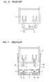
Figs. 10, 11 ,13 ,15, and 16 are schematic diagrams illustrating conventional optical connectors, in which some parts are indicated simply. For example, unlike the actual shape shown inFigs. 12 and14 , theblade springs - The
receptacle body 2 slides in the direction opposite to that of arrow A2 with respect to theshield cover 6 as shown inFig. 11 to mate with theshield cover 6 as shown inFig. 13 . During the sliding,projections receptacle body 2 make contact with thelight emitting element 3 and thelight receiving element 4, respectively, and push theelement holder 5 including thelight emitting element 3 and thelight receiving element 4 in the direction of arrow A3 (downward direction inFig. 13 or rightward direction inFig. 12 ). This pressing locates thelight guide 1 in an appropriate position with respect to thelight emitting element 3 and thelight receiving element 4.Fig. 14 is an exploded perspective view of a conventional optical connector. - In the conventional optical connector described in
non-patent document 1, however, there may be play between thelight guide 1 and thereceptacle body 2 after thereceptacle body 2 mates with theshield cover 6. This play changes the gap between thelight guide 1 and thelight emitting element 3 andlight receiving element 4 and changes the amount of light that leaks as a loss, possibly destabilizing the optical characteristics. - To address the above problem, the present invention provides an urging means for urging the light guide in the direction in which the light guide is inserted into the receptacle body when the receptacle body has mated with the shield cover.
- The urging means urges the light guide in the direction in which the light guide is inserted into the receptacle body when the receptacle body has mated with the shield cover, so no play is generated between the light guide and receptacle body. Accordingly, the present invention has an effect of stabilizing the optical characteristics.
-
-
Fig. 1 is an exploded perspective view of an exemplary optical connector according to the present invention. -
Fig. 2 is an exploded perspective view of the exemplary optical connector according to the present invention. -
Fig. 3 is a cross-sectional view of the exemplary optical connector according to the present invention. -
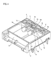
Fig. 4 is a cross-sectional perspective view of the exemplary optical connector according to the present invention. -
Fig. 5 is a diagram illustrating the lengths ofblade springs -
Fig. 6 is a schematic diagram illustrating an exemplary urging means according to the present invention. -
Fig. 7 is a schematic diagram illustrating an exemplary urging means according to the present invention. -
Fig. 8 is a schematic diagram illustrating an exemplary urging means according to the present invention. -
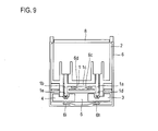
Fig. 9 is a schematic diagram illustrating an exemplary urging means according to the present invention. -
Fig. 10 is a diagram illustrating a conventional optical connector. -
Fig. 11 is a diagram illustrating the conventional optical connector. -
Fig. 12 is a cross-sectional view of the conventional optical connector. -
Fig. 13 is a diagram illustrating the conventional optical connector. -
Fig. 14 is an exploded perspective view of the conventional optical connector. -
Fig. 15 is a diagram illustrating the conventional optical connector. -
Fig. 16 is a diagram illustrating the conventional optical connector. - Embodiments of the present invention will be described below with reference to the drawings.
- A
light guide 1 has a sending side opticallyfunctional section 1a, which optically connects alight emitting element 3 and a transmission optical fiber, a receiving side opticallyfunctional section 1b, which optically connects a light receivingelement 4 and a reception optical fiber, and ajoint section 1c, which connects between the sending side opticallyfunctional section 1a and the receiving side opticallyfunctional section 1b. The sending side opticallyfunctional section 1 a, the receiving side opticallyfunctional section 1b, and thejoint section 1c are made of light-transmitting synthetic resin and molded integrally by injection molding. - The sending side optically
functional section 1a and the receiving side opticallyfunctional section 1b are cylindrical. Thejoint section 1c is provided with a v-shaped groove for preventing light from leaking between the sending side opticallyfunctional section 1a and the receiving side opticallyfunctional section 1b. To prevent light from leaking between the sending side opticallyfunctional section 1a and the receiving side opticallyfunctional section 1b, the sending side opticallyfunctional section 1a and the receiving side opticallyfunctional section 1b are in contact with thejoint section 1c so that the circumferential length of an area where the sending side opticallyfunctional section 1a and the receiving side opticallyfunctional section 1b are in contact with thejoint section 1c becomes shorter than half of the outer circumferences of the sending side opticallyfunctional section 1a and the receiving side opticallyfunctional section 1b. - The
light guide 1 is inserted into areceptacle body 2. That is, one end of the sending side opticallyfunctional section 1a and one end of the receiving side opticallyfunctional section 1b are inserted intoholes receptacle body 2, respectively. The diameters of theholes receptacle body 2 and a transmission optical fiber terminal (not shown) and a reception optical fiber terminal (not shown) are inserted into the section with the increased diameter. - The upper surface of the
receptacle body 2 is covered with acover 7. Thecover 7 supports ashutter 8 in a rotatable manner. Theshutter 8 is urged by atwisted coil spring 9 in the direction in which theshutter 8 is closed. Accordingly, if the transmission optical fiber terminal and the reception optical fiber terminal are not inserted into thereceptacle body 2, theshutter 8 closes to prevent the entrance of foreign matter that may degrade the optical characteristics. If an attempt is made to insert the transmission optical fiber terminal and the reception optical fiber terminal into thereceptacle body 2, the transmission optical fiber terminal and the reception optical fiber terminal make contact with theshutter 8 and pushes up theshutter 8. That is, theshutter 8 rotates in the direction in which theshutter 8 approaches thecover 7. - The
light emitting element 3 and thelight receiving element 4 are held in anelement holder 5. Theholder 5 is placed in ashield cover 6. Theshield cover 6 hasblade springs element holder 5 in the downward direction inFig. 3 . In this way, thelight emitting element 3 and thelight receiving element 4 are held in theelement holder 5, which is placed in theshield cover 6. - The
shield cover 6 hasopenings functional section 1a and the receiving side opticallyfunctional section 1b of thelight guide 1 andprojections receptacle body 2 are inserted. Blade springs 6c and 6d, urging means, are provided between theopenings blade spring shield cover 6. Theblade spring shield cover 6 and extend toward the centers of theopenings - The
receptacle body 2 into which thelight guide 1 is inserted slides to mate with theshield cover 6, which holds thelight emitting element 3 and thelight receiving element 4. When thereceptacle body 2 has mated with theshield cover 6, anend 1d of the sending side opticallyfunctional section 1a and anend 1e of the receiving side opticallyfunctional section 1b of thelight guide 1 face thelight emitting element 3 and thelight receiving element 4, respectively. - When the
receptacle body 2 has mated with theshield cover 6, theblade spring light guide 1 in the direction in which thelight guide 1 is inserted into thereceptacle body 2. This prevents play between thelight guide 1 and thereceptacle body 2 from generating, thereby eliminating the looseness of thelight guide 1. - As shown in
Fig. 15 , thereceptacle body 2 may not completely mate with thelight guide 1 due to operation error or the like, so theends light guide 1 may project above theprojections receptacle body 2. In this case, if the blade springs 6c and 6d, the urging means, are not present, sliding thereceptacle body 2 toward theshield cover 6 brings theend 1d of the sending side opticallyfunctional section 1a and theend 1e of the receiving side opticallyfunctional section 1b into contact with thelight emitting element 3 and thelight receiving element 4, respectively, before theprojections receptacle body 2 make contact with thelight emitting element 3 and thelight receiving element 4, respectively. This may scratch or dent theend 1d of the sending side opticallyfunctional section 1a, theend 1e of the receiving side opticallyfunctional section 1b, thelight emitting element 3, and thelight receiving element 4, possibly degrading the optical characteristics of the optical connector. - When the blade springs 6c and 6d project sufficiently above the
inner surface 6e of the shield cover 6 (the amount of projection is described later), even if thelight guide 1 is not completely inserted into thereceptacle body 2 due to operation error or the like, sliding thereceptacle body 2 toward theshield cover 6 brings the blade springs 6c and 6d into contact with thejoint section 1c of thelight guide 1 before theend 1d of the sending side opticallyfunctional section 1a and theend 1e of the receiving side opticallyfunctional section 1b make contact with thelight emitting element 3 and thelight receiving element 4, respectively, and the resulting elastic force inserts thelight guide 1 into thereceptacle body 2 completely. Accordingly, if the blade springs 6c and 6d project sufficiently above theinner surface 6e of theshield cover 6, it is possible to reduce the probability of degradation in the optical characteristics of the optical connector due to scratches and dents made in theend 1d of the sending side opticallyfunctional section 1a, theend 1e of the receiving side opticallyfunctional section 1b, thelight emitting element 3, and thelight receiving element 4 when thereceptacle body 2 slides to mate with theshield cover 6. - Referring to
Fig. 5 , the proper amount of projection of the blade springs 6c and 6d from theinner surface 6e of theshield cover 6 is described below. Thelight emitting element 3 portion that faces theend 1d of the sending side opticallyfunctional section 1a is assumed to be anarea 3a; thelight receiving element 4 portion that faces theend 1e of the receiving side opticallyfunctional section 1b is assumed to be anarea 4a. Theblade spring 6c portion that makes contact with thelight guide 1 is assumed to be anarea 6f; theblade spring 6d portion that makes contact with thelight guide 1 is assumed to be anarea 6g. The distance, in the direction in which thereceptacle body 2 slides, between thearea 3a and thearea 6f and between thearea 4a and thearea 6g when the blade springs 6c and 6d are not in contact with thelight guide 1 is assumed to be L1. Thelight guide 1 portion that makes contact with theblade spring 6c is assumed to be apoint 1f; thelight guide 1 portion that makes contact with theblade spring 6d is assumed to be apoint 1g. The end face of theend 1d of the sending side opticallyfunctional section 1a is assumed to be 1h; the end face of theend 1e of the sending side opticallyfunctional section 1b is assumed to be 1i. The distance between thearea 1f and theend face 1h and the distance between thearea 1h and theend face 1i are assumed to be L2. - If the
blade spring inner surface 6e of theshield cover 6 so that L1 becomes greater than L2, it is possible to reduce the probability of degradation in the optical characteristics of the optical connector due to scratches and dents made in theend 1d of the sending side opticallyfunctional section 1a, theend 1e of the receiving side opticallyfunctional section 1b, thelight emitting element 3, and thelight receiving element 4 when thereceptacle body 2 slides to mate with theshield cover 6. - When the
receptacle body 2 has mated with theshield cover 6, the blade springs 6c and 6d urge thelight guide 1 in the direction in which the sending side opticallyfunctional section 1a and the receiving side opticallyfunctional section 1b move away from thelight emitting element 3 and thelight receiving element 4, respectively. That is, theblade spring 6c urges thelight guide 1 in the direction in which the sending side opticallyfunctional section 1a moves away from thelight emitting element 3 and theblade spring 6d urges thelight guide 1 in the direction in which the receiving side opticallyfunctional section 1b moves away from thelight receiving element 4. As described above, if the urging means for urging thelight guide 1 in the direction in which the sending side opticallyfunctional section 1a and the receiving side opticallyfunctional section 1b move away from thelight emitting element 3 and thelight receiving element 4, respectively, it is possible to effectively prevent the sending side opticallyfunctional section 1a and the receiving side opticallyfunctional section 1b from making contact with thelight emitting element 3 and thelight receiving element 4, respectively. It is also possible to effectively prevent the gap between the sending side opticallyfunctional section 1a and thelight emitting element 3 and the gap between the receiving side opticallyfunctional section 1b and thelight receiving element 4 from varying. - These urging means are not limited to the blade springs 6c and 6d illustrated schematically in
Figs. 3 ,4 , and9 . As illustrated schematically inFig. 6 , blade springs 1j and 1k, which are the urging means, can be molded integrally with thelight guide 1. As illustrated schematically inFig. 7 , blade springs 5a and 5b, which are the urging means, can be molded integrally with theelement holder 5. In this case, the blade springs 5a and 5b pass through through-holes (not shown) formed in theshield cover 6 and make contact with thelight guide 1. The urging means may be any elastic body other than blade springs and may be twocoil springs 11 into which the sending side opticallyfunctional section 1a and the receiving side opticallyfunctional section 1b are inserted, as illustrated schematically inFig. 8 . - It will be appreciated that various modifications may be made as appropriate without departing from the scope of the invention.
Claims (7)
- An optical connector comprising:a shield cover holding a light emitting element and a light receiving element;a light guide including a sending side optically functional section optically connecting the light emitting element and a transmission optical fiber and a receiving side optically functional section optically connecting the light receiving element and a reception optical fiber, the light guide being made of light-transmitting synthetic resin;a receptacle body into which the light guide is inserted, the receptacle body being slidable with respect to the shield cover to mate with the shield cover; andan urging means urging the light guide in a direction in which the light guide is inserted into the receptacle body when the receptacle body mates with the shield cover;wherein an end of the sending side optically functional section faces the light emitting element and an end of the receiving side optically functional section of the light guide faces the light receiving element when the receptacle body has mated with the shield cover.
- The optical connector of claim 1, wherein a distance, in the direction in which the receptacle body slides, between a portion that each of the ends of the sending side optically functional section and the receiving side optically functional section of the light emitting element and the light receiving element faces and a portion of the urging means with which the urging means is to make contact when the urging means is not contact with the light guide is greater than a distance, in the direction in which the receptacle body slides, between a portion of the light guide with which the urging means is to make contact and each of end faces of the ends of the sending side optically functional section and the receiving side optically functional section.
- The optical connector of claim 1 or 2, wherein the urging means urges the light guide in a direction in which the sending side optically functional section and the receiving side optically functional section move away from the light emitting element and the light receiving element, respectively, when the receptacle body has mated with the shield cover.
- The optical connector of any one of claims 1 to 3, wherein the urging means is provided on the shield cover.
- The optical connector of any one of claims 1 to 3, wherein the urging means is provided on the light guide.
- The optical connector of any one of claims 1 to 3, wherein the light emitting element and the light receiving element are held in an element holder, the element holder being placed in the shield cover, and the urging means is provided on the element holder.
- The optical connector of any one of claims 1 to 3, wherein the urging means includes two coil springs into which the sending side optically functional section and the receiving side optically functional section are inserted.
Applications Claiming Priority (1)
| Application Number | Priority Date | Filing Date | Title |
|---|---|---|---|
| JP2008327221A JP4750178B2 (en) | 2008-12-24 | 2008-12-24 | Optical connector |
Publications (2)
| Publication Number | Publication Date |
|---|---|
| EP2202551A1 true EP2202551A1 (en) | 2010-06-30 |
| EP2202551B1 EP2202551B1 (en) | 2012-05-02 |
Family
ID=41720518
Family Applications (1)
| Application Number | Title | Priority Date | Filing Date |
|---|---|---|---|
| EP09015731A Not-in-force EP2202551B1 (en) | 2008-12-24 | 2009-12-18 | Optical connector |
Country Status (7)
| Country | Link |
|---|---|
| US (1) | US8292520B2 (en) |
| EP (1) | EP2202551B1 (en) |
| JP (1) | JP4750178B2 (en) |
| KR (1) | KR101646784B1 (en) |
| CN (1) | CN101833148A (en) |
| AT (1) | ATE556340T1 (en) |
| TW (1) | TWI481133B (en) |
Cited By (1)
| Publication number | Priority date | Publication date | Assignee | Title |
|---|---|---|---|---|
| CN103026557A (en) * | 2010-08-31 | 2013-04-03 | 日本航空电子工业株式会社 | Combined photoelectric connector and receptacle for same |
Families Citing this family (5)
| Publication number | Priority date | Publication date | Assignee | Title |
|---|---|---|---|---|
| US5883995A (en) | 1997-05-20 | 1999-03-16 | Adc Telecommunications, Inc. | Fiber connector and adapter |
| US10114184B2 (en) | 2014-12-31 | 2018-10-30 | Ls Mtron Ltd. | Optical connector |
| KR102019740B1 (en) * | 2014-12-31 | 2019-09-09 | 엘에스엠트론 주식회사 | Optical connector |
| JP2017009727A (en) * | 2015-06-19 | 2017-01-12 | 矢崎総業株式会社 | Optical connector |
| WO2023286304A1 (en) * | 2021-07-16 | 2023-01-19 | ソニーグループ株式会社 | Optical device and image display device |
Citations (4)
| Publication number | Priority date | Publication date | Assignee | Title |
|---|---|---|---|---|
| US5802230A (en) * | 1997-03-05 | 1998-09-01 | Fujitsu Limited | Optical semiconductor module |
| EP1510843A1 (en) * | 2003-08-25 | 2005-03-02 | Mitsumi Electric Co., Ltd. | Optical connector |
| DE102006005070A1 (en) * | 2005-02-03 | 2006-08-17 | Yazaki Corp. | Optical connector for use in the field of optical communication has a pair of convex sections on the wall of shielding housing, arranged opposite to the rear surface of light transmitting and light receiving-fiber optic transceiver |
| WO2007033611A1 (en) * | 2005-09-26 | 2007-03-29 | Hongkong Applied Science And Technology Research Institute Co., Ltd. | Opto-electronic device for optical fibre applications |
Family Cites Families (6)
| Publication number | Priority date | Publication date | Assignee | Title |
|---|---|---|---|---|
| JP3321571B2 (en) * | 1992-09-09 | 2002-09-03 | シャープ株式会社 | Photoelectric transmission equipment, holders, optical fiber cables and equipment |
| JP3909853B2 (en) * | 2004-04-26 | 2007-04-25 | 株式会社東芝 | Semiconductor laser device and semiconductor laser assembly |
| TWI404985B (en) * | 2004-11-04 | 2013-08-11 | Hosiden Corp | Optical coupling components for optical communication connectors |
| JP4559952B2 (en) * | 2004-11-04 | 2010-10-13 | ホシデン株式会社 | Optical coupling member for optical communication connector, optical connector using the same, and optical connector assembling method |
| JP4523874B2 (en) * | 2005-06-01 | 2010-08-11 | ホシデン株式会社 | Optical connector |
| JP4464913B2 (en) * | 2005-12-21 | 2010-05-19 | ホシデン株式会社 | Bidirectional optical communication connector |
-
2008
- 2008-12-24 JP JP2008327221A patent/JP4750178B2/en not_active Expired - Fee Related
-
2009
- 2009-12-03 TW TW098141371A patent/TWI481133B/en not_active IP Right Cessation
- 2009-12-09 KR KR1020090121494A patent/KR101646784B1/en not_active Expired - Fee Related
- 2009-12-18 AT AT09015731T patent/ATE556340T1/en active
- 2009-12-18 EP EP09015731A patent/EP2202551B1/en not_active Not-in-force
- 2009-12-22 US US12/644,010 patent/US8292520B2/en not_active Expired - Fee Related
- 2009-12-23 CN CN200910261949A patent/CN101833148A/en active Pending
Patent Citations (4)
| Publication number | Priority date | Publication date | Assignee | Title |
|---|---|---|---|---|
| US5802230A (en) * | 1997-03-05 | 1998-09-01 | Fujitsu Limited | Optical semiconductor module |
| EP1510843A1 (en) * | 2003-08-25 | 2005-03-02 | Mitsumi Electric Co., Ltd. | Optical connector |
| DE102006005070A1 (en) * | 2005-02-03 | 2006-08-17 | Yazaki Corp. | Optical connector for use in the field of optical communication has a pair of convex sections on the wall of shielding housing, arranged opposite to the rear surface of light transmitting and light receiving-fiber optic transceiver |
| WO2007033611A1 (en) * | 2005-09-26 | 2007-03-29 | Hongkong Applied Science And Technology Research Institute Co., Ltd. | Opto-electronic device for optical fibre applications |
Cited By (3)
| Publication number | Priority date | Publication date | Assignee | Title |
|---|---|---|---|---|
| CN103026557A (en) * | 2010-08-31 | 2013-04-03 | 日本航空电子工业株式会社 | Combined photoelectric connector and receptacle for same |
| US9063300B2 (en) | 2010-08-31 | 2015-06-23 | Japan Aviation Electronics Industry Limited | Electrical-optical hybrid connector and receptacle thereof |
| CN103026557B (en) * | 2010-08-31 | 2015-06-24 | 日本航空电子工业株式会社 | Combined photoelectric connector and receptacle for same |
Also Published As
| Publication number | Publication date |
|---|---|
| JP2010151901A (en) | 2010-07-08 |
| US8292520B2 (en) | 2012-10-23 |
| CN101833148A (en) | 2010-09-15 |
| KR101646784B1 (en) | 2016-08-08 |
| EP2202551B1 (en) | 2012-05-02 |
| KR20100075384A (en) | 2010-07-02 |
| ATE556340T1 (en) | 2012-05-15 |
| JP4750178B2 (en) | 2011-08-17 |
| TWI481133B (en) | 2015-04-11 |
| US20100158451A1 (en) | 2010-06-24 |
| TW201037923A (en) | 2010-10-16 |
Similar Documents
| Publication | Publication Date | Title |
|---|---|---|
| EP2202551B1 (en) | Optical connector | |
| US7712974B2 (en) | Method of assembling an optical connector and an optical connector | |
| KR101422991B1 (en) | Optical connector | |
| US7413351B2 (en) | Optical connection apparatus which has a shutter and which can be designed to be small in size | |
| US7794155B1 (en) | Fiber optic connector system | |
| KR101357811B1 (en) | Optical coupling structure, and optical coupling structure assembly method | |
| US5828805A (en) | Multifiber connector plug | |
| EP0803748A1 (en) | Multifibre connector plug | |
| US6945705B2 (en) | Optical connector | |
| JP2017227727A (en) | Optical transceiver | |
| US10067296B2 (en) | Optical connector component | |
| JP4927012B2 (en) | Light guide member fixing structure for FOT | |
| KR20150033848A (en) | LC type Field Installation Connector | |
| JP2012027320A (en) | Optical fiber connector | |
| JP5269746B2 (en) | Optical connector | |
| JP5950841B2 (en) | Optical connection member, optical connection structure | |
| JP6092550B2 (en) | Electronic component assembly | |
| JP4752634B2 (en) | Optical connector | |
| JP2017026867A (en) | Optical connector | |
| JP4829073B2 (en) | Optical connector plug with light shielding function | |
| JP5508103B2 (en) | Optical cable connector | |
| JP2010128456A (en) | Optical connector | |
| JP2008286893A (en) | Optical connector | |
| JP2012173343A (en) | Optical connector device | |
| JP2015014643A (en) | Waterproof plug having built-in multi-fiber optical connector |
Legal Events
| Date | Code | Title | Description |
|---|---|---|---|
| PUAI | Public reference made under article 153(3) epc to a published international application that has entered the european phase |
Free format text: ORIGINAL CODE: 0009012 |
|
| AK | Designated contracting states |
Kind code of ref document: A1 Designated state(s): AT BE BG CH CY CZ DE DK EE ES FI FR GB GR HR HU IE IS IT LI LT LU LV MC MK MT NL NO PL PT RO SE SI SK SM TR |
|
| AX | Request for extension of the european patent |
Extension state: AL BA RS |
|
| 17P | Request for examination filed |
Effective date: 20101217 |
|
| GRAP | Despatch of communication of intention to grant a patent |
Free format text: ORIGINAL CODE: EPIDOSNIGR1 |
|
| RIC1 | Information provided on ipc code assigned before grant |
Ipc: G02B 6/42 20060101AFI20110926BHEP |
|
| GRAS | Grant fee paid |
Free format text: ORIGINAL CODE: EPIDOSNIGR3 |
|
| GRAA | (expected) grant |
Free format text: ORIGINAL CODE: 0009210 |
|
| AK | Designated contracting states |
Kind code of ref document: B1 Designated state(s): AT BE BG CH CY CZ DE DK EE ES FI FR GB GR HR HU IE IS IT LI LT LU LV MC MK MT NL NO PL PT RO SE SI SK SM TR |
|
| REG | Reference to a national code |
Ref country code: GB Ref legal event code: FG4D |
|
| REG | Reference to a national code |
Ref country code: AT Ref legal event code: REF Ref document number: 556340 Country of ref document: AT Kind code of ref document: T Effective date: 20120515 Ref country code: CH Ref legal event code: EP |
|
| REG | Reference to a national code |
Ref country code: IE Ref legal event code: FG4D |
|
| REG | Reference to a national code |
Ref country code: DE Ref legal event code: R096 Ref document number: 602009006689 Country of ref document: DE Effective date: 20120705 |
|
| REG | Reference to a national code |
Ref country code: NL Ref legal event code: T3 |
|
| REG | Reference to a national code |
Ref country code: LT Ref legal event code: MG4D Effective date: 20120502 |
|
| PG25 | Lapsed in a contracting state [announced via postgrant information from national office to epo] |
Ref country code: PL Free format text: LAPSE BECAUSE OF FAILURE TO SUBMIT A TRANSLATION OF THE DESCRIPTION OR TO PAY THE FEE WITHIN THE PRESCRIBED TIME-LIMIT Effective date: 20120502 Ref country code: IS Free format text: LAPSE BECAUSE OF FAILURE TO SUBMIT A TRANSLATION OF THE DESCRIPTION OR TO PAY THE FEE WITHIN THE PRESCRIBED TIME-LIMIT Effective date: 20120902 Ref country code: NO Free format text: LAPSE BECAUSE OF FAILURE TO SUBMIT A TRANSLATION OF THE DESCRIPTION OR TO PAY THE FEE WITHIN THE PRESCRIBED TIME-LIMIT Effective date: 20120802 Ref country code: SE Free format text: LAPSE BECAUSE OF FAILURE TO SUBMIT A TRANSLATION OF THE DESCRIPTION OR TO PAY THE FEE WITHIN THE PRESCRIBED TIME-LIMIT Effective date: 20120502 Ref country code: CY Free format text: LAPSE BECAUSE OF FAILURE TO SUBMIT A TRANSLATION OF THE DESCRIPTION OR TO PAY THE FEE WITHIN THE PRESCRIBED TIME-LIMIT Effective date: 20120502 Ref country code: FI Free format text: LAPSE BECAUSE OF FAILURE TO SUBMIT A TRANSLATION OF THE DESCRIPTION OR TO PAY THE FEE WITHIN THE PRESCRIBED TIME-LIMIT Effective date: 20120502 Ref country code: LT Free format text: LAPSE BECAUSE OF FAILURE TO SUBMIT A TRANSLATION OF THE DESCRIPTION OR TO PAY THE FEE WITHIN THE PRESCRIBED TIME-LIMIT Effective date: 20120502 |
|
| REG | Reference to a national code |
Ref country code: AT Ref legal event code: MK05 Ref document number: 556340 Country of ref document: AT Kind code of ref document: T Effective date: 20120502 |
|
| PG25 | Lapsed in a contracting state [announced via postgrant information from national office to epo] |
Ref country code: PT Free format text: LAPSE BECAUSE OF FAILURE TO SUBMIT A TRANSLATION OF THE DESCRIPTION OR TO PAY THE FEE WITHIN THE PRESCRIBED TIME-LIMIT Effective date: 20120903 Ref country code: LV Free format text: LAPSE BECAUSE OF FAILURE TO SUBMIT A TRANSLATION OF THE DESCRIPTION OR TO PAY THE FEE WITHIN THE PRESCRIBED TIME-LIMIT Effective date: 20120502 Ref country code: HR Free format text: LAPSE BECAUSE OF FAILURE TO SUBMIT A TRANSLATION OF THE DESCRIPTION OR TO PAY THE FEE WITHIN THE PRESCRIBED TIME-LIMIT Effective date: 20120502 Ref country code: SI Free format text: LAPSE BECAUSE OF FAILURE TO SUBMIT A TRANSLATION OF THE DESCRIPTION OR TO PAY THE FEE WITHIN THE PRESCRIBED TIME-LIMIT Effective date: 20120502 Ref country code: GR Free format text: LAPSE BECAUSE OF FAILURE TO SUBMIT A TRANSLATION OF THE DESCRIPTION OR TO PAY THE FEE WITHIN THE PRESCRIBED TIME-LIMIT Effective date: 20120803 |
|
| PG25 | Lapsed in a contracting state [announced via postgrant information from national office to epo] |
Ref country code: BE Free format text: LAPSE BECAUSE OF FAILURE TO SUBMIT A TRANSLATION OF THE DESCRIPTION OR TO PAY THE FEE WITHIN THE PRESCRIBED TIME-LIMIT Effective date: 20120502 |
|
| PG25 | Lapsed in a contracting state [announced via postgrant information from national office to epo] |
Ref country code: EE Free format text: LAPSE BECAUSE OF FAILURE TO SUBMIT A TRANSLATION OF THE DESCRIPTION OR TO PAY THE FEE WITHIN THE PRESCRIBED TIME-LIMIT Effective date: 20120502 Ref country code: SK Free format text: LAPSE BECAUSE OF FAILURE TO SUBMIT A TRANSLATION OF THE DESCRIPTION OR TO PAY THE FEE WITHIN THE PRESCRIBED TIME-LIMIT Effective date: 20120502 Ref country code: DK Free format text: LAPSE BECAUSE OF FAILURE TO SUBMIT A TRANSLATION OF THE DESCRIPTION OR TO PAY THE FEE WITHIN THE PRESCRIBED TIME-LIMIT Effective date: 20120502 Ref country code: CZ Free format text: LAPSE BECAUSE OF FAILURE TO SUBMIT A TRANSLATION OF THE DESCRIPTION OR TO PAY THE FEE WITHIN THE PRESCRIBED TIME-LIMIT Effective date: 20120502 Ref country code: AT Free format text: LAPSE BECAUSE OF FAILURE TO SUBMIT A TRANSLATION OF THE DESCRIPTION OR TO PAY THE FEE WITHIN THE PRESCRIBED TIME-LIMIT Effective date: 20120502 Ref country code: RO Free format text: LAPSE BECAUSE OF FAILURE TO SUBMIT A TRANSLATION OF THE DESCRIPTION OR TO PAY THE FEE WITHIN THE PRESCRIBED TIME-LIMIT Effective date: 20120502 |
|
| PG25 | Lapsed in a contracting state [announced via postgrant information from national office to epo] |
Ref country code: IT Free format text: LAPSE BECAUSE OF FAILURE TO SUBMIT A TRANSLATION OF THE DESCRIPTION OR TO PAY THE FEE WITHIN THE PRESCRIBED TIME-LIMIT Effective date: 20120502 |
|
| PLBE | No opposition filed within time limit |
Free format text: ORIGINAL CODE: 0009261 |
|
| STAA | Information on the status of an ep patent application or granted ep patent |
Free format text: STATUS: NO OPPOSITION FILED WITHIN TIME LIMIT |
|
| 26N | No opposition filed |
Effective date: 20130205 |
|
| PG25 | Lapsed in a contracting state [announced via postgrant information from national office to epo] |
Ref country code: ES Free format text: LAPSE BECAUSE OF FAILURE TO SUBMIT A TRANSLATION OF THE DESCRIPTION OR TO PAY THE FEE WITHIN THE PRESCRIBED TIME-LIMIT Effective date: 20120813 |
|
| REG | Reference to a national code |
Ref country code: DE Ref legal event code: R097 Ref document number: 602009006689 Country of ref document: DE Effective date: 20130205 |
|
| PG25 | Lapsed in a contracting state [announced via postgrant information from national office to epo] |
Ref country code: BG Free format text: LAPSE BECAUSE OF FAILURE TO SUBMIT A TRANSLATION OF THE DESCRIPTION OR TO PAY THE FEE WITHIN THE PRESCRIBED TIME-LIMIT Effective date: 20120802 Ref country code: MC Free format text: LAPSE BECAUSE OF NON-PAYMENT OF DUE FEES Effective date: 20121231 |
|
| REG | Reference to a national code |
Ref country code: IE Ref legal event code: MM4A |
|
| PG25 | Lapsed in a contracting state [announced via postgrant information from national office to epo] |
Ref country code: IE Free format text: LAPSE BECAUSE OF NON-PAYMENT OF DUE FEES Effective date: 20121218 |
|
| PG25 | Lapsed in a contracting state [announced via postgrant information from national office to epo] |
Ref country code: MT Free format text: LAPSE BECAUSE OF FAILURE TO SUBMIT A TRANSLATION OF THE DESCRIPTION OR TO PAY THE FEE WITHIN THE PRESCRIBED TIME-LIMIT Effective date: 20120502 |
|
| PG25 | Lapsed in a contracting state [announced via postgrant information from national office to epo] |
Ref country code: TR Free format text: LAPSE BECAUSE OF FAILURE TO SUBMIT A TRANSLATION OF THE DESCRIPTION OR TO PAY THE FEE WITHIN THE PRESCRIBED TIME-LIMIT Effective date: 20120502 |
|
| PG25 | Lapsed in a contracting state [announced via postgrant information from national office to epo] |
Ref country code: LU Free format text: LAPSE BECAUSE OF NON-PAYMENT OF DUE FEES Effective date: 20121218 Ref country code: SM Free format text: LAPSE BECAUSE OF FAILURE TO SUBMIT A TRANSLATION OF THE DESCRIPTION OR TO PAY THE FEE WITHIN THE PRESCRIBED TIME-LIMIT Effective date: 20120502 |
|
| PG25 | Lapsed in a contracting state [announced via postgrant information from national office to epo] |
Ref country code: HU Free format text: LAPSE BECAUSE OF FAILURE TO SUBMIT A TRANSLATION OF THE DESCRIPTION OR TO PAY THE FEE WITHIN THE PRESCRIBED TIME-LIMIT Effective date: 20091218 |
|
| REG | Reference to a national code |
Ref country code: CH Ref legal event code: PL |
|
| PG25 | Lapsed in a contracting state [announced via postgrant information from national office to epo] |
Ref country code: LI Free format text: LAPSE BECAUSE OF NON-PAYMENT OF DUE FEES Effective date: 20131231 Ref country code: CH Free format text: LAPSE BECAUSE OF NON-PAYMENT OF DUE FEES Effective date: 20131231 |
|
| PG25 | Lapsed in a contracting state [announced via postgrant information from national office to epo] |
Ref country code: MK Free format text: LAPSE BECAUSE OF FAILURE TO SUBMIT A TRANSLATION OF THE DESCRIPTION OR TO PAY THE FEE WITHIN THE PRESCRIBED TIME-LIMIT Effective date: 20120502 |
|
| REG | Reference to a national code |
Ref country code: FR Ref legal event code: PLFP Year of fee payment: 7 |
|
| REG | Reference to a national code |
Ref country code: FR Ref legal event code: PLFP Year of fee payment: 8 |
|
| REG | Reference to a national code |
Ref country code: FR Ref legal event code: PLFP Year of fee payment: 9 |
|
| REG | Reference to a national code |
Ref country code: FR Ref legal event code: PLFP Year of fee payment: 10 |
|
| PGFP | Annual fee paid to national office [announced via postgrant information from national office to epo] |
Ref country code: NL Payment date: 20210929 Year of fee payment: 13 |
|
| PGFP | Annual fee paid to national office [announced via postgrant information from national office to epo] |
Ref country code: GB Payment date: 20211028 Year of fee payment: 13 Ref country code: DE Payment date: 20211231 Year of fee payment: 13 |
|
| PGFP | Annual fee paid to national office [announced via postgrant information from national office to epo] |
Ref country code: FR Payment date: 20211012 Year of fee payment: 13 |
|
| REG | Reference to a national code |
Ref country code: DE Ref legal event code: R119 Ref document number: 602009006689 Country of ref document: DE |
|
| REG | Reference to a national code |
Ref country code: NL Ref legal event code: MM Effective date: 20230101 |
|
| GBPC | Gb: european patent ceased through non-payment of renewal fee |
Effective date: 20221218 |
|
| PG25 | Lapsed in a contracting state [announced via postgrant information from national office to epo] |
Ref country code: NL Free format text: LAPSE BECAUSE OF NON-PAYMENT OF DUE FEES Effective date: 20230101 |
|
| PG25 | Lapsed in a contracting state [announced via postgrant information from national office to epo] |
Ref country code: GB Free format text: LAPSE BECAUSE OF NON-PAYMENT OF DUE FEES Effective date: 20221218 Ref country code: DE Free format text: LAPSE BECAUSE OF NON-PAYMENT OF DUE FEES Effective date: 20230701 |
|
| PG25 | Lapsed in a contracting state [announced via postgrant information from national office to epo] |
Ref country code: FR Free format text: LAPSE BECAUSE OF NON-PAYMENT OF DUE FEES Effective date: 20221231 |