EP2202463A2 - Gas cooking hob - Google Patents
Gas cooking hob Download PDFInfo
- Publication number
- EP2202463A2 EP2202463A2 EP09178243A EP09178243A EP2202463A2 EP 2202463 A2 EP2202463 A2 EP 2202463A2 EP 09178243 A EP09178243 A EP 09178243A EP 09178243 A EP09178243 A EP 09178243A EP 2202463 A2 EP2202463 A2 EP 2202463A2
- Authority
- EP
- European Patent Office
- Prior art keywords
- support member
- gas hob
- gas
- hob
- upper support
- Prior art date
- Legal status (The legal status is an assumption and is not a legal conclusion. Google has not performed a legal analysis and makes no representation as to the accuracy of the status listed.)
- Withdrawn
Links
Images


Classifications
-
- F—MECHANICAL ENGINEERING; LIGHTING; HEATING; WEAPONS; BLASTING
- F24—HEATING; RANGES; VENTILATING
- F24C—DOMESTIC STOVES OR RANGES ; DETAILS OF DOMESTIC STOVES OR RANGES, OF GENERAL APPLICATION
- F24C15/00—Details
- F24C15/10—Tops, e.g. hot plates; Rings
-
- F—MECHANICAL ENGINEERING; LIGHTING; HEATING; WEAPONS; BLASTING
- F24—HEATING; RANGES; VENTILATING
- F24C—DOMESTIC STOVES OR RANGES ; DETAILS OF DOMESTIC STOVES OR RANGES, OF GENERAL APPLICATION
- F24C15/00—Details
- F24C15/08—Foundations or supports plates; Legs or pillars; Casings; Wheels
-
- F—MECHANICAL ENGINEERING; LIGHTING; HEATING; WEAPONS; BLASTING
- F24—HEATING; RANGES; VENTILATING
- F24C—DOMESTIC STOVES OR RANGES ; DETAILS OF DOMESTIC STOVES OR RANGES, OF GENERAL APPLICATION
- F24C3/00—Stoves or ranges for gaseous fuels
- F24C3/008—Ranges
Definitions
- the delay or the lack of flatness of the upper support member on the lower support member may be visible to the naked eye and then affects the appearance of the hob. Furthermore, in gas hobs, the performance of the hob can be affected if occur due to the lack of flatness of the upper support element air pressure surges in the hob. Such air pressure surges can, for example be triggered by closing the doors of base units of the hob and accidentally extinguish the gas flame.
- the support elements known from the aforementioned publications are used in particular to support the comparatively high weight of conventional steel hotplates.
- the present invention has the object, a gas hob of the type mentioned in such a way that the upper support member has a particularly high flexural rigidity and reliable rests flat on the lower support member ,
- the present invention is based on the fact that for stabilizing the upper support member on the lower support member side facing the upper support member is arranged at least one stiffening element, which is supported on the support member, for example on a support screw and / or on a support pin.
- This stiffening element is arranged flat on the upper support element, thus extending substantially horizontally.
- the stiffening element may have any areal geometry. It is preferably a profile, that is to say an elongated component, for example an elongate plate or a rail or a strip.
- the profile preferably has a beveled, for example quadrangular, cross section.
- the stiffening element extends over the entire length or the entire width of the hob, so from a side wall of the upper support member to the opposite side wall. As a result, over the entire length or the entire width of the hob, a flat position of the upper support member is effected on the lower support member.
- stiffening element only in a selected, for example central, region of the upper support element.
- the stiffening element and the supporting element are preferably arranged in the region of the operating elements for operating the cooking zones. This gives the upper support element in its front region a particularly high flexural rigidity.
- the support element extends substantially horizontally. Thus, it takes up little space in the hob. This is particularly advantageous in gas hobs with numerous electronic components.
- the length of the region of the support element arranged in the gas hob can preferably be changed.
- the support element can be used for different depth gas hobs.
- a length adjustable support member can be adjusted so that the upper support member rests flat on both the hot and under cold conditions on the lower support member.
- the support member may be, for example, a screw passed through the bottom of the lower support member.
- the length of the area arranged in the gas hob This screw can be varied by screwing the screw at different depths into the gas hob.
- FIG. 1 shows an embodiment of a gas hob 100 according to the present invention.
- This gas hob 100 is composed of an upper support member 40, namely a cooktop cover plate, and a lower support member 50, namely a cooktop cavity, together.
- the gas hob 100 has five gas hobs 20 and controls 30 for operating the gas hobs 20.
- a profile 42 On the side of the upper support element facing the lower support element 50, a profile 42, namely a strip, is glued in the area of the control elements 30.
- This bar 42 serves to increase the flexural rigidity of the upper support member 40.
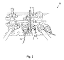
- the bar 42 is shown in an enlarged view.
- the bar 42 is supported on support screws 10.
- the support elements 10 arranged in the lower support element thus press against the upper support element 40 via the profile 42.
- these support screws 10 are guided through the bottom 60 of the lower support member 50.
- the support screws 10 are arranged in recesses 62, more precisely in boreholes, of the lower support element 50. In this way, the length of the gas hob 100 arranged region of the support screws 10 can be chosen arbitrarily.
- the support bolts 10 have over support rails or other surface arranged in the lower support member 50 supporting elements have the advantage that they occupy very little space. For example, they can be arranged between the gas connection 70 and the ignition connection 80 (cf. FIG. 3 ).
Abstract
Description
Die vorliegende Erfindung betrifft ein Gaskochfeld mit
- einem oberen Tragelement, in dem mindestens eine Gaskochstelle angeordnet ist, und
- einem mit dem oberen Tragelement verbundenen unteren Tragelement, das mindestens ein Stützelement zum Stützen des oberen Tragelements aufweist, wobei das Stützelement zumindest bereichsweise im Gaskochfeld angeordnet ist und sich vertikal zum oberen Tragelement hin erstreckt.
- an upper support element, in which at least one gas hob is arranged, and
- a connected to the upper support member lower support member having at least one support member for supporting the upper support member, wherein the support member is at least partially disposed in the gas hob and extends vertically to the upper support member.
Bei herkömmlichen Kochfeldern tritt häufig das Problem auf, dass diese sich verziehen und das obere Tragelement, das so genannte top sheet, nicht plan auf dem unteren Tragelement, dem so genannten bottom sheet, aufliegt. Dieses Verziehen kann bei der Herstellung des Kochfelds auftreten, beispielsweise aufgrund des unterschiedlichen Rückverformungsverhaltens verschiedener Rohmaterial-Chargen. Ferner kann sich das Kochfeld auch bei seinem Gebrauch verziehen oder eine bei der Herstellung des Kochfelds aufgetretene Verformung noch verstärkt werden, da die beim Kochen entstehende Hitze und das Gewicht der Pfannen oder Töpfe das Kochfeld deformieren können. Diese Deformationen treten bei flachen Kochfeldern umso häufiger und ausgeprägter auf, da sich mit abnehmender Tiefe der Kochmulde auch deren Biegesteifigkeit verringert.In conventional hobs, the problem often occurs that these warp and the top support element, the so-called top sheet, not flat on the bottom support element, the so-called bottom sheet rests. This distortion can occur in the production of the hob, for example due to the different recovery behavior of different raw material batches. Further, the hob can also warp in its use or a occurred in the production of the hob deformation be amplified because the heat generated during cooking and the weight of the pans or pots can deform the hob. These deformations occur in flat hobs all the more frequent and pronounced, as it decreases with decreasing depth of the cooktop and their bending stiffness.
Der Verzug bzw. die mangelnde Planlage des oberen Tragelements auf dem unteren Tragelement kann mit bloßem Auge sichtbar sein und beeinträchtigt dann die Optik des Kochfelds. Ferner kann bei Gaskochfeldern auch die Leistung des Kochfelds beeinträchtigt werden, wenn durch die mangelnde Planlage des oberen Tragelements Luftdruckstöße im Kochfeld auftreten. Derartige Luftdruckstöße können beispielsweise durch das Schließen der Türen von Unterschränken des Kochfelds ausgelöst werden und die Gasflamme unbeabsichtigt löschen.The delay or the lack of flatness of the upper support member on the lower support member may be visible to the naked eye and then affects the appearance of the hob. Furthermore, in gas hobs, the performance of the hob can be affected if occur due to the lack of flatness of the upper support element air pressure surges in the hob. Such air pressure surges can, for example be triggered by closing the doors of base units of the hob and accidentally extinguish the gas flame.
Aus den Druckschriften
Ausgehend von den vorstehend dargelegten Nachteilen und Unzulänglichkeiten sowie unter Würdigung des umrissenen Standes der Technik liegt der vorliegenden Erfindung die Aufgabe zugrunde, ein Gaskochfeld der eingangs genannten Art so weiterzubilden, dass das obere Tragelement eine besonders hohe Biegesteifigkeit aufweist und zuverlässig plan auf dem unteren Tragelement aufliegt.Based on the disadvantages and inadequacies set forth above and in appreciation of the outlined prior art, the present invention has the object, a gas hob of the type mentioned in such a way that the upper support member has a particularly high flexural rigidity and reliable rests flat on the lower support member ,
Diese Aufgabe wird durch ein Gaskochfeld mit den im Anspruch 1 angegebenen Merkmalen gelöst. Vorteilhafte Ausgestaltungen und zweckmäßige Weiterbildungen der vorliegenden Erfindung sind in den Unteransprüchen gekennzeichnet.This object is achieved by a gas hob with the features specified in claim 1. Advantageous embodiments and expedient developments of the present invention are characterized in the subclaims.
Mithin basiert die vorliegende Erfindung darauf, dass zum Stabilisieren des oberen Tragelements an der dem unteren Tragelement zugewandten Seite des oberen Tragelements mindestens ein Versteifungselement angeordnet ist, das sich auf dem Stützelement, beispielsweise auf einer Stützschraube und/oder auf einem Stützstift, abstützt. Dieses Versteifungselement ist flächig am oberen Tragelement angeordnet, erstreckt sich also im Wesentlichen horizontal. Hierdurch wird der durch das Stützelement ausgeübte Druck über die Fläche des Versteifungselements verteilt, so dass das obere Tragelement an seiner gesamten mit dem Versteifungselement versehenen Fläche vom Stützelement abgestützt wird.Thus, the present invention is based on the fact that for stabilizing the upper support member on the lower support member side facing the upper support member is arranged at least one stiffening element, which is supported on the support member, for example on a support screw and / or on a support pin. This stiffening element is arranged flat on the upper support element, thus extending substantially horizontally. As a result, the pressure exerted by the support member pressure is distributed over the surface of the stiffening member, so that the upper support member is supported on its entire surface provided with the stiffening member by the support member.
Das Versteifungselement kann eine beliebige flächige Geometrie aufweisen. Vorzugsweise ist es ein Profil, also ein langgestrecktes Bauteil, beispielsweise eine langgestreckte Platte oder eine Schiene oder eine Leiste. Das Profil weist vorzugsweise einen abgekanteten, beispielsweise viereckigen, Querschnitt auf.The stiffening element may have any areal geometry. It is preferably a profile, that is to say an elongated component, for example an elongate plate or a rail or a strip. The profile preferably has a beveled, for example quadrangular, cross section.
Gemäß einer vorteilhaften Ausführungsform der vorliegenden Erfindung erstreckt sich das Versteifungselement über die gesamte Länge bzw. die gesamte Breite des Kochfelds, also von einer Seitenwand des oberen Tragelements zu deren gegenüberliegenden Seitenwand. Hierdurch wird über die gesamte Länge bzw. die gesamte Breite des Kochfelds eine Planlage des oberen Tragelements auf dem unteren Tragelement bewirkt.According to an advantageous embodiment of the present invention, the stiffening element extends over the entire length or the entire width of the hob, so from a side wall of the upper support member to the opposite side wall. As a result, over the entire length or the entire width of the hob, a flat position of the upper support member is effected on the lower support member.
Es ist aber auch möglich, das Versteifungselement nur in einem ausgewählten, beispielsweise zentralen, Bereich des oberen Tragelements anzuordnen.But it is also possible to arrange the stiffening element only in a selected, for example central, region of the upper support element.
Damit sich das Gaskochfeld insbesondere in seinem der Bedienseite zugewandten Frontbereich nicht verzieht, sind das Versteifungselement und das Stützelement vorzugsweise im Bereich der Bedienelemente zum Bedienen der Kochstellen angeordnet. Dies verleiht dem oberen Tragelement in seinem Frontbereich eine besonders hohe Biegesteifigkeit.So that the gas hob does not distort, in particular in its front side facing the operating side, the stiffening element and the supporting element are preferably arranged in the region of the operating elements for operating the cooking zones. This gives the upper support element in its front region a particularly high flexural rigidity.
Das Stützelement erstreckt sich im Wesentlichen horizontal. Somit nimmt es im Kochfeld nur wenig Raum in Anspruch. Dies ist insbesondere bei Gaskochfeldern mit zahlreichen elektronischen Komponenten von Vorteil.The support element extends substantially horizontally. Thus, it takes up little space in the hob. This is particularly advantageous in gas hobs with numerous electronic components.
Die Länge des im Gaskochfeld angeordneten Bereichs des Stützelements ist vorzugsweise veränderbar. Somit kann das Stützelement für unterschiedlich tiefe Gaskochfelder verwendet werden. Auch kann ein in seiner Länge anpassbares Stützelement so eingestellt werden, dass das obere Tragelement sowohl unter heißen als auch unter kalten Bedingungen plan auf dem unteren Tragelement aufliegt.The length of the region of the support element arranged in the gas hob can preferably be changed. Thus, the support element can be used for different depth gas hobs. Also, a length adjustable support member can be adjusted so that the upper support member rests flat on both the hot and under cold conditions on the lower support member.
Das Stützelement kann beispielsweise eine durch den Boden des unteren Tragelements durchgeführte Schraube sein. Die Länge des im Gaskochfeld angeordneten Bereichs dieser Schraube kann variiert werden, indem die Schraube unterschiedlich tief in das Gaskochfeld eingeschraubt wird.The support member may be, for example, a screw passed through the bottom of the lower support member. The length of the area arranged in the gas hob This screw can be varied by screwing the screw at different depths into the gas hob.
Wie bereits vorstehend erörtert, gibt es verschiedene Möglichkeiten, die Lehre der vorliegenden Erfindung in vorteilhafter Weise auszugestalten und weiterzubilden. Hierzu wird einerseits auf die dem Anspruch 1 nachgeordneten Ansprüche verwiesen, andererseits werden weitere Ausgestaltungen, Merkmale und Vorteile der vorliegenden Erfindung nachstehend unter anderem anhand des durch die
- Fig. 1Fig. 1
- in Explosionsdarstellung ein Ausführungsbeispiel für ein Gaskochfeld gemäß der vorliegenden Erfindung;an exploded view of an embodiment of a gas hob according to the present invention;
- Fig. 2Fig. 2
-
in vergrößerter Darstellung ein im unteren Tragelement angeordnetes Stützelement des Gaskochfelds aus
Figur 1 ;in an enlarged view arranged in the lower support member supporting element of the gas hobFIG. 1 ; - Fig. 3Fig. 3
-
eine Draufsicht auf die vom oberen Tragelement abgewandte Seite des unteren Tragelements des Gaskochfelds aus
Figur 1 ;a plan view of the side facing away from the upper support member side of the lower support member of the gas hobFIG. 1 ; - Fig. 4Fig. 4
-
eine Draufsicht auf die dem unteren Tragelement zugewandte Seite des oberen Tragelements des Gaskochfelds aus
Figur 1 .a plan view of the lower support member facing side of the upper support member of the gas hobFIG. 1 ,
Gleiche oder ähnliche Ausgestaltungen, Elemente oder Merkmale sind in den
Das Gaskochfeld 100 hat fünf Gaskochstellen 20 und Bedienelemente 30 zum Bedienen der Gaskochstellen 20.The
An der dem unteren Tragelement 50 zugewandten Seite des oberen Tragelements ist im Bereich der Bedienelemente 30 ein Profil 42, nämlich eine Leiste, angeklebt. Diese Leiste 42 dient zum Erhöhen der Biegesteifigkeit des oberen Tragelements 40. In
Im zusammengebauten Zustand des Gaskochfelds 100 stützt sich die Leiste 42 auf Stützschrauben 10 ab. Die im unteren Tragelement angeordneten Stützelemente 10 drücken also über das Profil 42 gegen das obere Tragelement 40.In the assembled state of the
Wie in den
Die Stützschrauben 10 weisen gegenüber Stützschienen oder anderen flächig im unteren Tragelement 50 angeordneten Stützelementen den Vorteil auf, dass sie nur sehr wenig Raum einnehmen. So können sie beispielsweise zwischen dem Gasanschluss 70 und dem Zündanschluss 80 angeordnet werden (vgl.
- 100100
- Gaskochfeld bzw. GaskochmuldeGas hob or gas hob
- 1010
- Stützelement, insbesondere Stützschraube oder StützstiftSupport element, in particular support screw or support pin
- 2020
- GaskochstelleGas Cooking
- 3030
-
Bedienelement zum Bedienen der Gaskochstelle 20Operating element for operating the
gas hob 20 - 4040
- oberes Tragelement, insbesondere Kochfelddeckplatte bzw. so genanntes top sheet, oder Oberschale des Kochfelds 100Upper support member, in particular cooktop cover plate or so-called top sheet, or top shell of the hob 100th
- 4242
- Versteifungselement, insbesondere langgestrecktes Bauteil, beispielsweise Schiene, Leiste oder Platte, zum Versteifen des oberen Tragelements 40Stiffening element, in particular elongated component, such as rail, strip or plate, for stiffening the upper support member 40th
- 4444
-
Seitenwand des oberen Tragelements 40Side wall of the
upper support element 40 - 5050
- unteres Tragelement, insbesondere Bodenplatte bzw. so genanntes bottom sheet, oder Unterschale, beispielsweise Kochfeldmulde oder Muldenblech, des Kochfeldslower support element, in particular bottom plate or so-called bottom sheet, or lower shell, for example, hob trough or tray plate of the hob
- 6060
-
Boden des unteren Tragelements 50Bottom of the
lower support element 50 - 6262
-
Ausnehmung, beispielsweise Bohrloch, des unteren Tragelements 50 zum Anordnen des Stützelements 10Recess, for example, borehole, of the
lower support member 50 for arranging the support member 10th - 7070
-
Zündanschluss des Gaskochfelds 100Ignition connection of the
gas hob 100 - 8080
-
Gasanschluss des Gaskochfelds 100Gas connection of the
gas hob 100
Claims (12)
Applications Claiming Priority (1)
| Application Number | Priority Date | Filing Date | Title |
|---|---|---|---|
| ES200900077A ES2382063B1 (en) | 2008-12-29 | 2008-12-29 | GAS COOKING PLATE |
Publications (2)
| Publication Number | Publication Date |
|---|---|
| EP2202463A2 true EP2202463A2 (en) | 2010-06-30 |
| EP2202463A3 EP2202463A3 (en) | 2017-06-21 |
Family
ID=42115784
Family Applications (1)
| Application Number | Title | Priority Date | Filing Date |
|---|---|---|---|
| EP09178243.3A Withdrawn EP2202463A3 (en) | 2008-12-29 | 2009-12-08 | Gas cooking hob |
Country Status (2)
| Country | Link |
|---|---|
| EP (1) | EP2202463A3 (en) |
| ES (1) | ES2382063B1 (en) |
Cited By (1)
| Publication number | Priority date | Publication date | Assignee | Title |
|---|---|---|---|---|
| WO2015198173A1 (en) | 2014-06-25 | 2015-12-30 | BSH Hausgeräte GmbH | Gas cooking point and hob |
Family Cites Families (7)
| Publication number | Priority date | Publication date | Assignee | Title |
|---|---|---|---|---|
| US2040346A (en) * | 1933-09-22 | 1936-05-12 | Teller Stove Designing Corp | Stove and range construction |
| DE1753389B1 (en) * | 1962-05-21 | 1970-10-01 | Siemens Elektrogeraete Gmbh | Hob for electric hotplates, especially for installation in a worktop |
| DE2048718B1 (en) * | 1970-10-03 | 1972-06-08 | Siemens-Electrogeräte GmbH, 1000 Berlin u. 8000 München | Built-in hob |
| US3785364A (en) * | 1972-06-05 | 1974-01-15 | Columbia Gas Syst Service Corp | Smooth top range |
| US4032750A (en) * | 1976-03-26 | 1977-06-28 | General Electric Company | Flat plate heating unit with foil heating means |
| US5406932A (en) * | 1992-10-23 | 1995-04-18 | Canadian Gas Research Institute | Sealed combustion range |
| WO2008148769A2 (en) * | 2007-06-04 | 2008-12-11 | Arcelik Anonim Sirketi | A cooking range |
-
2008
- 2008-12-29 ES ES200900077A patent/ES2382063B1/en not_active Expired - Fee Related
-
2009
- 2009-12-08 EP EP09178243.3A patent/EP2202463A3/en not_active Withdrawn
Non-Patent Citations (1)
| Title |
|---|
| None * |
Cited By (1)
| Publication number | Priority date | Publication date | Assignee | Title |
|---|---|---|---|---|
| WO2015198173A1 (en) | 2014-06-25 | 2015-12-30 | BSH Hausgeräte GmbH | Gas cooking point and hob |
Also Published As
| Publication number | Publication date |
|---|---|
| EP2202463A3 (en) | 2017-06-21 |
| ES2382063A1 (en) | 2012-06-05 |
| ES2382063B1 (en) | 2013-05-07 |
Similar Documents
| Publication | Publication Date | Title |
|---|---|---|
| EP1954097A1 (en) | Method for creating an induction cooker and induction cooker | |
| DE102008056715A1 (en) | Force plate | |
| EP2099257B1 (en) | Hotplate | |
| DE19912452A1 (en) | Installation bar for a cooktop | |
| EP2790468B1 (en) | Cooking hob and method for fitting a cooking hob | |
| EP2202463A2 (en) | Gas cooking hob | |
| DE102005055438B4 (en) | Hob | |
| DE2340818C3 (en) | Support frame for an electric hotplate | |
| EP1979682A1 (en) | Cooking hob | |
| EP2532799B1 (en) | Metal girder and its use | |
| EP2202464A2 (en) | Cooking hob | |
| EP1882143B1 (en) | Built-in household device with an adjusting rail | |
| EP2372267A2 (en) | Support for solar modules | |
| EP3379900B1 (en) | Hotplate | |
| DE102015208238A1 (en) | Edge formwork element with a formwork panel for producing a concrete slab | |
| DE202014104306U1 (en) | Furniture panel made of wood or a wooden material | |
| WO2007088090A2 (en) | Cooking appliance, especially built-in wall cooking appliance, and method for producing the same | |
| DE102005042526A1 (en) | Cooking basin for inserting in a section of an oven sill plate has a cooking-basin plate and a framework strip to support the cooking-basin plate on the oven sill plate | |
| DE2820725C3 (en) | Clamping device for spaced opposing formwork walls | |
| WO2006131495A1 (en) | Cooking pan | |
| DE102005040260A1 (en) | Baking-oven door, has glass plates, where embossing, thermal expansion coefficient and adjustment of plates in frame for inclusion of air gap are selected such that distance remains constant or is increased during oven heating | |
| DE3706578C2 (en) | ||
| CH716975A1 (en) | Ceiling element for a heating and cooling ceiling. | |
| DE102012109589B4 (en) | furniture | |
| DE927411C (en) | One-piece, slotted stove top |
Legal Events
| Date | Code | Title | Description |
|---|---|---|---|
| PUAI | Public reference made under article 153(3) epc to a published international application that has entered the european phase |
Free format text: ORIGINAL CODE: 0009012 |
|
| AK | Designated contracting states |
Kind code of ref document: A2 Designated state(s): AT BE BG CH CY CZ DE DK EE ES FI FR GB GR HR HU IE IS IT LI LT LU LV MC MK MT NL NO PL PT RO SE SI SK SM TR |
|
| RAP1 | Party data changed (applicant data changed or rights of an application transferred) |
Owner name: BSH HAUSGERAETE GMBH |
|
| PUAL | Search report despatched |
Free format text: ORIGINAL CODE: 0009013 |
|
| AK | Designated contracting states |
Kind code of ref document: A3 Designated state(s): AT BE BG CH CY CZ DE DK EE ES FI FR GB GR HR HU IE IS IT LI LT LU LV MC MK MT NL NO PL PT RO SE SI SK SM TR |
|
| RIC1 | Information provided on ipc code assigned before grant |
Ipc: F24C 15/10 20060101AFI20170518BHEP Ipc: F24C 3/00 20060101ALI20170518BHEP |
|
| 17P | Request for examination filed |
Effective date: 20171221 |
|
| RBV | Designated contracting states (corrected) |
Designated state(s): AT BE BG CH CY CZ DE DK EE ES FI FR GB GR HR HU IE IS IT LI LT LU LV MC MK MT NL NO PL PT RO SE SI SK SM TR |
|
| 17Q | First examination report despatched |
Effective date: 20180305 |
|
| GRAP | Despatch of communication of intention to grant a patent |
Free format text: ORIGINAL CODE: EPIDOSNIGR1 |
|
| INTG | Intention to grant announced |
Effective date: 20180713 |
|
| STAA | Information on the status of an ep patent application or granted ep patent |
Free format text: STATUS: THE APPLICATION IS DEEMED TO BE WITHDRAWN |
|
| 18D | Application deemed to be withdrawn |
Effective date: 20181124 |