EP2202165A1 - Box body - Google Patents
Box body Download PDFInfo
- Publication number
- EP2202165A1 EP2202165A1 EP08834357A EP08834357A EP2202165A1 EP 2202165 A1 EP2202165 A1 EP 2202165A1 EP 08834357 A EP08834357 A EP 08834357A EP 08834357 A EP08834357 A EP 08834357A EP 2202165 A1 EP2202165 A1 EP 2202165A1
- Authority
- EP
- European Patent Office
- Prior art keywords
- container
- lid
- constituting
- opening
- constituting portion
- Prior art date
- Legal status (The legal status is an assumption and is not a legal conclusion. Google has not performed a legal analysis and makes no representation as to the accuracy of the status listed.)
- Granted
Links
Images






Classifications
-
- B—PERFORMING OPERATIONS; TRANSPORTING
- B65—CONVEYING; PACKING; STORING; HANDLING THIN OR FILAMENTARY MATERIAL
- B65D—CONTAINERS FOR STORAGE OR TRANSPORT OF ARTICLES OR MATERIALS, e.g. BAGS, BARRELS, BOTTLES, BOXES, CANS, CARTONS, CRATES, DRUMS, JARS, TANKS, HOPPERS, FORWARDING CONTAINERS; ACCESSORIES, CLOSURES, OR FITTINGS THEREFOR; PACKAGING ELEMENTS; PACKAGES
- B65D5/00—Rigid or semi-rigid containers of polygonal cross-section, e.g. boxes, cartons or trays, formed by folding or erecting one or more blanks made of paper
- B65D5/02—Rigid or semi-rigid containers of polygonal cross-section, e.g. boxes, cartons or trays, formed by folding or erecting one or more blanks made of paper by folding or erecting a single blank to form a tubular body with or without subsequent folding operations, or the addition of separate elements, to close the ends of the body
- B65D5/0254—Rigid or semi-rigid containers of polygonal cross-section, e.g. boxes, cartons or trays, formed by folding or erecting one or more blanks made of paper by folding or erecting a single blank to form a tubular body with or without subsequent folding operations, or the addition of separate elements, to close the ends of the body with end closures formed by inward folding of flaps and securing them by means of a tongue integral with one of the flaps
-
- B—PERFORMING OPERATIONS; TRANSPORTING
- B65—CONVEYING; PACKING; STORING; HANDLING THIN OR FILAMENTARY MATERIAL
- B65D—CONTAINERS FOR STORAGE OR TRANSPORT OF ARTICLES OR MATERIALS, e.g. BAGS, BARRELS, BOTTLES, BOXES, CANS, CARTONS, CRATES, DRUMS, JARS, TANKS, HOPPERS, FORWARDING CONTAINERS; ACCESSORIES, CLOSURES, OR FITTINGS THEREFOR; PACKAGING ELEMENTS; PACKAGES
- B65D5/00—Rigid or semi-rigid containers of polygonal cross-section, e.g. boxes, cartons or trays, formed by folding or erecting one or more blanks made of paper
- B65D5/42—Details of containers or of foldable or erectable container blanks
- B65D5/54—Lines of weakness to facilitate opening of container or dividing it into separate parts by cutting or tearing
- B65D5/5405—Lines of weakness to facilitate opening of container or dividing it into separate parts by cutting or tearing for opening containers formed by erecting a blank in tubular form
- B65D5/541—Lines of weakness to facilitate opening of container or dividing it into separate parts by cutting or tearing for opening containers formed by erecting a blank in tubular form the lines of weakness being provided in one or more closure flaps
-
- B—PERFORMING OPERATIONS; TRANSPORTING
- B65—CONVEYING; PACKING; STORING; HANDLING THIN OR FILAMENTARY MATERIAL
- B65D—CONTAINERS FOR STORAGE OR TRANSPORT OF ARTICLES OR MATERIALS, e.g. BAGS, BARRELS, BOTTLES, BOXES, CANS, CARTONS, CRATES, DRUMS, JARS, TANKS, HOPPERS, FORWARDING CONTAINERS; ACCESSORIES, CLOSURES, OR FITTINGS THEREFOR; PACKAGING ELEMENTS; PACKAGES
- B65D5/00—Rigid or semi-rigid containers of polygonal cross-section, e.g. boxes, cartons or trays, formed by folding or erecting one or more blanks made of paper
- B65D5/42—Details of containers or of foldable or erectable container blanks
- B65D5/64—Lids
- B65D5/66—Hinged lids
- B65D5/6602—Hinged lids formed by folding one or more extensions hinged to the upper edge of a tubular container body
- B65D5/6608—Hinged lids formed by folding one or more extensions hinged to the upper edge of a tubular container body the lid being held in closed position by self-locking integral flaps
-
- B—PERFORMING OPERATIONS; TRANSPORTING
- B65—CONVEYING; PACKING; STORING; HANDLING THIN OR FILAMENTARY MATERIAL
- B65D—CONTAINERS FOR STORAGE OR TRANSPORT OF ARTICLES OR MATERIALS, e.g. BAGS, BARRELS, BOTTLES, BOXES, CANS, CARTONS, CRATES, DRUMS, JARS, TANKS, HOPPERS, FORWARDING CONTAINERS; ACCESSORIES, CLOSURES, OR FITTINGS THEREFOR; PACKAGING ELEMENTS; PACKAGES
- B65D83/00—Containers or packages with special means for dispensing contents
Definitions
- the present invention relates to a container, which is preferably applied to a carton containing a lot of small sized articles, to be handled, such as PET bottles, cans, cigarettes, pencils, and filled parts and a package box for various kinds of electric equipment or the like, particularly, applied to a paper-made refill or the like for carrying and filling consumables in a binding system that is provided with a cartridge into which a plurality of the consumables each having a long shape are loaded in a stacked manner.
- a plurality of small sized articles, to be handled such as PET bottles, cans, cigarettes, pencils, and filled parts have been often distributed with a desired carton containing them or various kinds of electric equipment or the like have been often distributed with a package box using corrugated cardboard containing them.
- a carton or a package box is made by performing the taking of measurements on carton material or box material with a predetermined size, creating a development of the container, cutting notches into predetermined portions of the developed container and erecting the container by making mountain or valley fold on the carton or box material.
- a packing case for supplement of goods and a method of supplementing the goods for a vending machine using the same have been disclosed in Japanese Patent Application Publication No. Hei05-04640 .
- the goods are contained in the container so that they are aligned in a longitudinal direction thereof.
- the goods are bound by a band for fixing the goods.
- the band is fixed into the container at forward and rearward ends thereof.
- the container is set onto the vending machine with a forward end thereof being positioned at a downward direction. It is constituted that after setting, a perforated portion is separated so that the forward end is opened and then, the band for fixing the goods is disengaged.
- a package box has been disclosed in Japanese Patent Application Publication No. 2001-02057 .
- This package box has an outer container with a predetermined size and a triangular opening in an outer container configuration surface.
- an inner container is provided within the outer container.
- the inner container uses corrugated cardboard vertically.
- a lid-constituting portion is provided so as to extend from side surfaces of the outer container to an upper surface thereof continuously and is closed by a string on a predetermined position on the upper surface of the outer container.
- it is configured that a stripe pattern of the corrugated cardboard of the inner container is exposed from the triangular opening.
- a package with a dispenser has been disclosed in Japanese Patent Application Publication No. 2005-53555 .
- a container having the dispenser at its forward end portion is provided.
- a separation part is defined by cutting container-constituting portion that is constituted of side walls, an upper surface and a bottom surface of the forward end portion of the package into one with a predetermined size.
- An opening is obtained by folding a part by which a side of this separation part is common in the container-constituting portion and pulling out the separation part to a side of the container-constituting portion. It is constituted that when such an opened package is held so that its posture is directed to a vertical direction, the opening is positioned at a low position.
- the opening has such a size that allows a predetermined article contained in the package to be removed therefrom.
- a container having the dispenser at its forward end portion is provided.
- a displaceable portion is defined by cutting carton-constituting portion that is constituted of side walls, an upper surface and a bottom surface of the forward end portion of the container-constituting portion into one with a predetermined size.
- An opening is obtained by folding a part by which a side of this displaceable portion is common in the carton-constituting portion and tearing up the displaceable portion to this side.
- the opening when such an opened package is held so that its posture is directed to a horizontal direction, the opening is positioned at an upper position. It is constituted that the opening has such a size that allows a predetermined article contained in the carton to be removed therefrom. By taking such a configuration, it is capable of dispensing the article from the carton without tearing up the carton main body.
- the dispenser is formed by cutting the container-constituting portion that is constituted of side walls, an upper surface and a bottom surface of the forward end portion of the container-constituting surfaces into one with a predetermined size. Accordingly, if the container is installed into a vending machine, a binding machine or an automatic machine such as various kinds of power tools and the articles contained therein is provided (supplied) but a loading space is blocked in three directions when it has a dispenser configuration like ones disclosed in Japanese Patent Application Publication No.
- This invention solves the above-mentioned problems and has an object of providing a container that is capable of loading any contents onto a cassette for containing articles and the like with good reproducibility from inside of the container and is suitably applied to a paper-made refill, which is applicable to a vending machine, various kinds of parts cassettes or the like.
- a container according to the present invention in which one of container-constituting surfaces forms an opening with a predetermined size, is provided with, if two constituting surfaces standing facing each other across the opening are supposed as first and second constituting surfaces, at least a first folding surface that makes a mountain fold on the first constituting surface, the first folding surface having a width extending beyond the opening, and a second folding surface that makes a mountain fold on the first folding surface to engage the second constituting surface.
- the container is characterized in that when opening the opening, the second folding surface disengages the second constituting surface and the first folding surface is folded back to a position so that it becomes the same wall surface as that of the first constituting surface.
- the container according to the present invention when the contents are brought out with an opening side thereof facing downward, a side surface of any one of the contents contacts the continued wall surface formed by the wall surface constituted of the first constituting surface and the first folding surface along it. Accordingly, when loading the contents onto any desired cassette or the like for containing the articles, it is possible to control a posture of the contents each falling in parallel along the wall surface of the first folding surface, which is continuous with the wall surface of the first constituting surface. This enables the contents to be loaded onto the cartridge for containing the articles and the like with good reproducibility from inside of the container. Further, it is possible to apply the container suitably to a paper-made refill or the like, which is applicable to a vending machine, various kinds of parts cassettes or the like.
- the embodiment of the container 100 according to the invention, shown in FIG. 1 is applicable to a package box for a plurality of small sized articles, to be handled, such as PET bottles, cans, cigarettes, pencils, and filled parts and for various kinds of electric equipment or the like.
- this container 100 is applicable to a paper-made refill or the like for carrying and loading consumables, for which any contents in which a plurality of consumables each having long shape are stacked are handled in a binding system.
- one of container-constituting surfaces forms an opening 6 with a predetermined size. In other words, one of the six surfaces constituting the container 100 is opened.
- the container-constituting surface as a container-constituting portion (part).
- a size of the entire container 100 is constituted of a height H1, a length L1 and a width W1.
- a size of the opening 6 is obtained by multiplying L1 by W1.
- first container-constituting portion 1 and second container-constituting portion 2 a first lid-constituting portion 11 constituting a first folding surface is unfolded onto the container-constituting portion 1 as a side wall.
- the lid-constituting portion 11 extends continuously from a side prescribing the length L1 of the container-constituting portion 1 up to a length similar to the width W1 of the opening 6.
- the lid-constituting portion 11 has a width (length) extending beyond the opening 6 of L1 multiplied by W1.
- the lid-constituting portion 11 folds and makes a mountain fold on the container-constituting portion 1 on the basis of outside of the container.
- a lid-closing portion 12 and a lid-closing portion 13 are unfolded onto the lid-constituting portion 11.
- the lid-closing portion 12 and the lid-closing portion 13 make a mountain fold on the lid-constituting portion 11.
- the lid-closing portion 13 is formed so that it engages the container-constituting portion 2.
- lid-closing portion 12 extends continuously from a side prescribing the length of the lid-constituting portion 11 up to a width (length) W1' that is almost similar to the width W1 of the opening 6.
- the lid-closing portion 12 has a trapezoid such that both sides are cut and has an area less than that of the rectangular of the lid-constituting portion 11.
- the lid-closing portion 12 makes a mountain fold on the lid-constituting portion 11.
- the separable lid-closing portion 13 is unfolded onto the lid-closing portion 12.
- the lid-closing portion 13 extends continuously from a side prescribing the width of the lid-closing portion 12 up to a predetermined length.
- the lid-closing portion 13 has a predetermined shape and a size and is connected to the lid-closing portion 12 through a configuration of cuts 12a on the same plane.
- the lid-closing portion 13 is shaped so as to become a flat trapezoid with a protrusion 13a.
- the protrusion 13a constitutes a grip.
- an engaged portion 2a is provided in the container-constituting portion 2 at its predetermined position and an engaging portion 13b is provided in the lid-closing portion 13 at its predetermined position.
- the engaged portion 2a is formed by, for example, cutting a groove forming a slit at a position of the container-constituting portion 2, which lies slightly toward a side of the container-constituting portion 3 away from middle thereof.
- the engaging portion 13b is formed by cutting a groove in semicircle at a lower position of the protrusion 13a.
- the engaging portion 13b of the lid-closing portion 13 first disengages the engaged portion 2a of the container-constituting portion 2.
- the lid-closing portion 13 enters a state of disengaging the container-constituting portion 2.
- the lid-constituting portion 11 is folded back to a position so that it becomes the same wall surface as that of the container-constituting portion 1. Thereafter, the lid-closing portion 13 is cut off.
- container-constituting portions 3, 4 are arranged between the container-constituting portions 1 and 2.
- the container-constituting portion 3 is walled so that it constitutes a side wall.
- the container-constituting portion 4 is walled so that it constitutes the other side wall.
- a container-constituting portion 5 is walled.
- Configuring such a container 100 allows contents of the container 100 to be covered by the container-constituting portions 1, 2, the lid-constituting portion 11 and other container-constituting portions 3, 4 after the container has contained the contents and the opening 6 has closed. This also enables a predetermined shape of each of the contents to be kept. Further, if the contents are dropped and contained into a desired cassette or the like for containing articles while directing the opening 6 downward, the lid-closing portion 12, a posture of which is kept to a position almost perpendicular to the lid-constituting portion 11, can support the contents.
- the lid-closing portion 13 may be cut off under a condition such that weights of the contents are applied to the lid-closing portion 12.
- a container material 101 having a size like an exploded example of the container 100 shown in FIG. 2 is prepared.
- the container material 101 for example, coated cardboard with paper quality of 350 g/m 2 is used.
- a development may be drawn so that a coated surface thereof forms an inside of the container 100. This is because the parts contained in the container 100 are easy to slide inside the container and are easy to be loaded into an automatic machine or the like when loading the parts thereinto.
- the coated cardboard has a size constituted of a vertical length W0 and a horizontal length L0. Though depending on a finished measurement of the container 100, the vertical one W0 may be almost (5 through 7)W1+ H1 and the horizontal one L0 may be almost 2L1+2W1+a margin for connection or more.
- the container material 101 is not limited to the coated cardboard but corrugated cardboard, plastic panel with a predetermined thickness may be used therefor according to containing uses. If a container which can be used repeatedly again and again is formed, the container using the plastic panel can be increased in its used times more than that of a paper container.
- the container-constituting portions 1 and 2 each having length L1 and height H1, the container-constituting portions 3 and 4 each having width W1 and height H1, and the margin 7 for connection of height H1 are drawn above almost a half of the container material 101.
- the container-constituting portions 1 and 2, the container-constituting parts 3 and 4 and the margin 7 for connection are continuously arranged so that they are aligned horizontally.
- lid-constituting portion 11 of length L1 and width W1 the lid-closing portion 12, the trapezoidal lid-closing (separable) portion 13, and the protrusion 13a forming the grip are drawn below the container-constituting portion 1.
- These lid-constituting portion 11, lid-closing portion 12, lid-closing (separable) portion 13 and the protrusion 13a are arranged at positions that are continuous with the container-constituting portion 1.
- the engaged portion 2a is drawn in the container-constituting portion 2 and then is opened.
- a perforation is performed on a borderline of the lid-closing portions 12 and 13 so that the configuration of cuts 12a is formed.
- #1 and #2 depict folding lines.
- the folding line #1 forms a borderline of the container-constituting portion 1 and the lid-constituting portion 11 and the folding line #2 forms a borderline of the lid-constituting portion 11 and the lid-closing portion 12.
- a container-constituting portion 5 of length L next to the container-constituting portion 2 a container-constituting piece 5a of length W1 next to the container-constituting portion 3 a container-constituting portion 5 of length L next to the container-constituting portion 1, and a container-constituting piece 5b of length W1 next to the container-constituting portion 4 are drawn.
- a container-constituting piece 8a may be disposed on a position under the container-constituting portion 3 shown by alternate long and two short dashes line and a container-constituting piece 8b may be disposed on a position under the container-constituting portion 4 shown thereby.
- the container-constituting piece 8a makes a mountain fold on the container-constituting portion 3 next to the container-constituting portion 1.
- the container-constituting piece 8b makes a mountain fold on the container-constituting portion 4 next to the container-constituting portion 2.
- Disposition of the container-constituting pieces 8a, 8b enables the strength of the entire container 100 to be increased.
- the disposition of the container-constituting pieces 8a, 8b may be omitted.
- broken lines other than the folding lines #1 and #2 show positions for folding and making mountain folds thereon.
- a developed shape of the container 100 is completed as shown in FIG. 1 .
- the container 100 as shown in FIG. 7 can be completed.
- each of the container-constituting portions 1 through 4 and the margin 7 for connection in the developed form shown in FIG. 2 folds and makes a mountain fold to form the container-constituting portions 1 through 4 as a box.
- the container-constituting portion 4 and the margin 7 for connection are connected with each other by an adhesive, a staple or the like.
- the container-constituting pieces 5a, 5b to build up a bottom surface are then folded inwardly in advance and the container-constituting portions 5 fold and make mountain folds onto the container-constituting pieces 5a, 5b. It is constituted that butt portions of the container-constituting portions 5 are stuck by a tape or the like.
- the container 100 is obtained such that the lid-constituting portions 11, 12, the lid-closing portion 13 and the protrusion 13a forming the grip extend upwards in succession from the container-constituting portion 1 and the opening 6 is defined.
- articles 30 are contained into the container 100 from the opening 6 shown in FIG. 3 .
- the articles 30 are, for example, a plurality of small sized ones, to be handled, such as PET bottles, cans, cigarettes, pencils, and filled parts, various kinds of electric equipment or the like.
- the opening 6 is closed.
- the lid-constituting portion 11 folds and makes mountain folds on the folding positions (i).
- the lid-closing portion 12 folds and makes mountain folds on the folding positions (ii) so that the lid-closing portion 12 covers over the opening 6.
- the lid-constituting portion 11 and the lid-closing portion 12 then wraps a corner of the opening 6 on the folding position (ii) shown in FIG. 5 . Further, the lid-closing portions 12 and 13 cover over the container-constituting portion 2. As shown in FIG. 6A , the engaging portion 13b then engages the engaged portion 2a. In this embodiment, the semicircular engaging portion 13b is inserted into the engaged portion 2a, in the enlarged sectional view of FIG. 6B , from a front surface of the container-constituting portion 2 to a rear surface thereof. A forward end of the engaging portion 13b catches the engaged portion 2a so that the lid-closing portion 13 is locked.
- an engaging method is not limited thereto; a double-sided tape may stick the protrusion 13a forming the gripe and the container-constituting portion 2.
- the opening 6 in the container 100 can be firmly closed (see FIG. 7 ).
- the container 100 when completing closing the lid, it is possible to fix the lid-closing portion 13 on the container-constituting portion 1 exactly. Even if the container-constituting portion 5 is directed upward and a single lid structure part is directed downward, it is also possible to maintain the closed state of the opening 6 steadfastly as shown in FIG. 7 .
- Configuring such a container 100 allows the articles, which are easy to be separated, to be handled with ease by the container-constituting portions 1 through 5, the lid-constituting portion 11, and the lid-closing portions 12 and 13. It is capable of protecting the contents when carrying them or transporting them. When loading the articles, touching the contents directly with hand can be avoided so that it is possible to prevent the articles from being deformed.
- the protrusion 13a forming the grip which extends to this side, is pulled while the container 100 is loaded onto the automatic machine, the power tool or the like. This enables the lid-constituting portion 11 and the lid-closing portions 12 and 13 to be easily opened.
- the container 100 is loaded onto the automatic machine 400 or the like with a side of its lid-closing portion being directed downward.
- the automatic machine 400 shown in FIG. 8 is a vending machine, a binding machine, various kinds of power tools or the like and has a loading space 401 for loading the container 100 as shown in FIG. 7 .
- the loading space 401 is blocked in its three directions. Namely, there is a situation such that an operator's hand cannot enter into right and left side surfaces and a back surface of the loading space 401. A side of a bottom surface of the loading space 401 becomes parts-loading space 402, which has often such a structure that an operator's hand cannot enter into it depending on a type of automatic machine 400.
- the container 100 with a single lid structure according to the present invention When the container 100 with a single lid structure according to the present invention is loaded onto the automatic machine 400 having such a loading space 401, the container 100 is laded so that it is directed from an upper part of the loading space 401 to a lower part thereof or from a front surface thereof to a back surface thereof.
- a mechanism of stopping the container 100 at a middle of the loading space 401 is provided.
- a stopper mechanism is provided at the right or left side surface or a back surface of the loading space 401. It is configured that when dropping the container 100 from the upper part of the loading space 401 to a lower part thereof along it, the stopper mechanism stops movement of the container 100.
- Such a mechanism enables to be realized a structure in which the operator's hand can enter into a lower part of the loading space 401 under the container 100 stopping at a middle thereof, thereby keeping any working space.
- the lid-constituting portions 11 and the lid-closing portion 12 are opened by pulling the lid-closing portion 13 positioned at this side under a situation where the container 100 is loaded onto the above-mentioned loading space 401.
- FIGS. 10A and 10B , 11 , 12 , 13 and 14 a lid-opening example of the container 100 with reference to FIGS. 10A and 10B , 11 , 12 , 13 and 14 .
- the container 100 having the single lid structure according to the invention is loaded onto the automatic machine 400 shown in FIG. 8 and the articles 30 are loaded thereto, and the configuration of cuts 12a is provided at a predetermined position of the lid-closing portion 12, which is away from the engaging portion 13b of the lid-closing portion 13 by a predetermined distance.
- a posture of the lid-closing portion 12 is kept at a position that is almost perpendicular to the lid-constituting portion 11.
- the container 100 is loaded onto the automatic machine 400 as shown in FIG. 9 .
- the opening 6 is opened.
- a user may pull the lid-closing portion 13 toward this side while the protrusion 13a (grip) thereof is held and pulled tight upward.
- the engaging portion 13b is pulled out of the engaged portion (slit portion) 2a so that the engaged portion 2a and the engaging portion 13b are separated from each other.
- the container 100 is operated so that the lid-constituting portion 11 is bent back in a direction of making valley folds based on the folding position (i) shown in FIG. 11 .
- a user moves the lid-constituting portion 11 backward while he is pulling the lid-closing portion 13 toward this side, thereby opening the opening 6.
- the articles 30 contained in the container 100 are barely held by a part of the lid-constituting portion 11 so as to become a situation just before the articles 30 drop.
- the bending-back operation in a direction of making valley folds based on the folding position (i) as shown in FIG. 12 goes on.
- the lid-constituting portion 11 and the container-constituting portion 1 form the same wall surface.
- the user moves the lid-constituting portion 11 backward while he is pulling the lid-closing portion 13 toward this side, thereby opening the opening 6.
- the articles 30 contained in the container 100 drop (fall in parallel) along a wall surface of the lid-constituting portion 11.
- the lid-closing portion 13 is then separated from the lid-closing portion 12 through a borderline of the configuration of cuts 12a shown in FIG. 13 .
- the user operates to pull the protrusion 13a of the lid-closing portion 13 strongly toward this side with him holding it.
- the container 100 is then pulled upward.
- the lid-closing portion 12 is bent back based on the folding position (ii) that is almost perpendicular from the lid-closing portion 12, a posture of which is kept to the lid-constituting portion 11.
- the lid-closing portion 12 following the container-constituting portion 1 and the lid-constituting portion 11 form the same wall surface so that they wait with them contacting a side surface of each of the articles 30. This enables the articles 30 to be loaded onto the automatic machine 400.
- the side surface of each of the articles 30 when taking the articles 30 outside while a side of the opening 6 is directed downward, the side surface of each of the articles 30 is formed as to contact the continuous wall surface constituted of the wall surface formed by the container-constituting portion 1 and the wall surface formed by the lid-constituting portion 11 along it.
- This enables the falling-in-parallel posture of each of the articles 30 to be controlled so as to go along the wall surface of the lid-constituting portion 11 that is continuous from the wall surface of the container-constituting portion 1 when loading the articles 30 onto the cassette or the like for containing the articles.
- the container 100 is capable of taking the articles 30 out of inside of the container 100 with good reproducibility toward a downward direction while the side of the opening 6 is directed downward.
- the container 100 is suitably applied to a paper-made refill or the like, which is applicable to a vending machine, various kinds of parts cassettes or the like.
- this container 100 is suitably applicable to a refill for loading the consumables onto the binding system.
- FIG. 15 the single lid structure of the container 100 according to the invention is also provided and plural binding members as one example of the articles 30 are handled so as to contain them therein (see FIGS. 16A through 16C ).
- slits 1a, 1b for assisting opening or closing and positioning are provided in a container-constituting portion 1 on a vertical direction thereof and slits 1c, 1d for assisting opening and closing are provided in a container-constituting portion 2 on a vertical direction thereof.
- the slits 1a, 1b are provided at right and left two positions on the same plane of the container-constituting portion 1.
- the slits 1c, 1d are provided at right and left two positions on the same plane of the container-constituting portion 2. Length of each of the slits 1a through 1d is 11.
- the length 11 is set so as to be almost a half of a height H of the container 200. This is figured out to move the lid-constituting portion 11 easily further back and forth. It is possible to open the opening 6 wider than that of the first embodiment, which is easy to load the articles 30 in the container onto the cartridge or the like.
- a part of the container 200 that is positioned at an opposite side of a part thereof in which the single lid structure is arranged is a container-constituting portion 5c and the container-constituting portion 5c is provided with a handle 5e as shown in FIG. 17 . It is designed that the container 200 is easy to be carried.
- a display region 15 for an instruction manual is provided at an upper portion of the container-constituting portion 2 and any instruction procedure when loading the container 200 are printed thereon.
- the user may operate the lid-closing portions 13 and 12 (tab) or the like based on this instruction procedure.
- a part of the container-constituting portion 1 which is positioned at an opposite side of a part thereof in which the single lid structure is arranged, is a container-constituting portion 5g.
- the container-constituting portion 5g is provided with an opening 5f for the handle and an engaging piece 5h.
- the container-constituting portion 5c is provided with a slit 5i for being engaged with the engaging piece (see FIG. 17 ).
- names and signs similar to those of the first embodiment have the same functions as those thereof, an explanation of which will be omitted.
- the binding member 43 shown in FIG. 16A constitutes an example of the articles 30 and plural kinds thereof are manufactured according to thicknesses of bundles of paper to be bound in a binder.
- the binding member 43 is formed by utilizing a die-forming device.
- the binding member 43 is made of a resin-molding product that is constituted of a backbone portion 43a having a length that conforms to a size of a standard size paper (for example, A size) and ring portions 43b that are arranged with a fixed space, each becoming a ring shape.
- the binding members 43 are contained in the container 200 in groups of plural pieces thereof for every kind.
- each ring portion 43b is split into three parts which are an arc shaped ring part 43c that is connected with the backbone portion 43a and arc shaped ring parts 43d and 43e that are connected therewith so that they can be folded from side to side.
- a cross section of the backbone portion 43a has a shape in which a base is a straight line and an upper middle is convex.
- the arc shaped ring part 43c that becomes a predetermined ring portion 43b is provided with a projected pin 43f.
- the ring portion 43c is provided with a housing hole, not shown, corresponding to the pin 43f on a side thereof that is opposite to the side at which the pin 43f is provided.
- the stacked binding members 43 shown in FIG. 16C it is configured that plural binding members 43 are stacked by inserting each pin 43f into each housing hole while both ends of each of the arc shaped ring parts 43d, 43c and 43e that become the ring portion 43b shown in FIGS. 16A and 16B are aligned on almost a straight line. This enables the binding members 43 to be contained in the container 200 shown in FIG. 15 in groups of plural pieces thereof for every kind.
- the following will describe a method of manufacturing the container 200 with reference to a developed example of the container 200 shown in FIG. 17 .
- the container 200 having a simple structure and a minimum configuration without using another material can be presented.
- the container material 201 having, for example, a size shown in FIG. 17 is prepared.
- coated cardboard with paper quality of 350 g/m 2 is used, similar to the first embodiment.
- a development may be also drawn so that a coated surface thereof forms an inside of the container 200. The reason therefor has been described in the first embodiment, the description of which will be omitted.
- the coated cardboard has a size constituted of a vertical length W0' and a horizontal length L0.
- the container material 201 that is larger than that of the first embodiment is prepared to form the handle 5e and the container-constituting portion 5c.
- the vertical length W0' may be almost (5 through 7)W1+ H1 or more and the horizontal one L0 may be almost 2L1+2W1+a margin for connection or more.
- the container material 201 is not limited to the coated cardboard but the ones described in the first embodiment may be used therefor.
- the container material 201 shown in FIG. 17 is drawn, the slits 1a, 1b are provided in the container-constituting portion 1 and the slits 1c, 1d are provided in the container-constituting portion 2.
- triangles are drawn so that they project from both sides of the lid-constituting portion 11.
- the handle 5e is drawn on the container-constituting portion 5c.
- the container-constituting portion 5c is continuously extended from a side of the container-constituting portion 2, which is opposite to the side thereof in which the single lid structure is arranged.
- the opening (slit) 5f for the handle draws the container-constituting portion 5g.
- the container-constituting portion 5g is continuously extended from a side of the container-constituting portion 1, which is opposite to the side thereof in which the single lid structure is arranged.
- the engaging piece 5h is provided on the container-constituting portion 5g in addition to the opening 5f for the handle and the slit 5i for being engaged with the engaging piece is provided on the container-constituting portion 5c. This enables the container-constituting portion 5g to be held onto the slit 5i by inserting the engaging piece 5h into the slit 5i when erecting the container.
- the slit constituting the engaged portion 2a is provided on the container-constituting portion 2. It is configured so that the engaging portion 13b can be held onto the engaged portion 2a when erecting the container.
- a circular window 5d for checking color or the like of the contents is arranged on the container-constituting portion 5c.
- Other parts thereof are similar to those of FIG. 2 , the description of which will be omitted.
- a development of the container 200 is constituted and cutting and folding it allows the container 200 shown in FIG. 15 to be completed.
- This enables the container 200 for loading the consumables, which has a base shape that allows the binding members 43 to fall in parallel and the configuration of cuts 12a, to be constructed.
- the lid-constituting portion 11 having a configuration of one base is also provided so that the base shape of the lid-constituting portion 11 may prevent any binding members (consumables) 43 from being deformed.
- FIGS. 18A, 18B , 19A, 19B , 20A, 20B , 21A, 21B , 22A, 22B , 23A and 23B a case is illustrated where the engaging portion 13b of the lid-closing portion 13 is disengaged while a part in which the single lid structure is arranged is directed downward so that the opening 6 is opened.
- the plural binding members 43 shown in FIG. 16A are contained in the container 200 shown in FIG. 18A with them being stacked.
- the semicircular engaging portion 13b of the lid-closing portion 13 is inserted into the engaged portion 2a of the container-constituting portion 2 so that they are sealed. It is designed that the container 200 is carried with holding the handle 5e shown in FIG. 18B .
- the lid-closing portion 13 is taken out of the container-constituting portion 2 shown in FIG. 18A and the lid-closing portion 13 is pulled toward this side.
- the user pulls the lid-closing portion 13 toward this side while he holds the protrusion 13a (grip) thereof and pulls it tight upward. This allows the engaging portion 13b to disengage the engaged portion 2a (see FIG. 10B ).
- the container-constituting portion 1 is made curved larger than that of the first embodiment so that the opening 6 may be opened by a larger amount thereof (see FIG. 19B ).
- the container 200 is operated so that the lid-constituting portion 11 is bent back in a direction of making valley folds based on the folding position (i) shown in FIG. 19B .
- the user moves the lid-constituting portion 11 backward while he is pulling the lid-closing portion 13 toward this side, thereby opening the opening 6.
- the binding members 43 contained in the container 200 shown in FIG. 20A are barely held by a part of the lid-constituting portion 11 shown in FIG. 20B so as to become a situation just before the binding members 43 drop.
- the bending-back in a direction of making valley folds based on the folding positions (i), (ii) as shown in FIG. 20B goes on so that the lid-constituting portion 11 and the container-constituting portion 1 form the same wall surface.
- the user moves the lid-constituting portion 11 backward while he is pulling the lid-closing portion 13 toward this side, thereby opening the opening 6.
- the binding members 43 contained in the container 200 drop (fall in parallel) along a wall surface of the lid-constituting portion 11 (conventional free fall area).
- This free fall area occurs because a length of the groove on which the container 200 is inserted into the cartridge 42 is set to be made small in regard to an object to pack the binding members (stacked consumables) 43 by paper-made package as simple as possible and maintain its box shape.
- the falling-in-parallel posture of the binding members 43 is controlled in this free fall area.
- the binding members 43 contained in the container 200 shown in FIG. 21A become brought into a state where about a quarter thereof is exploded below from the opening 6.
- the lid-closing portion 12 is bent back based on the configuration of cuts 12a as shown in FIG. 22B .
- This enables the falling-in-parallel posture of the binding members 43 to be further controlled by the continuous wall surface constituted of the container-constituting portion 1, the lid-constituting portion 11 and the lid-closing portion 12.
- a side surface of each of the articles contacts it.
- the binding members 43 contained in the container 200 shown in FIG. 21A further fall in parallel as shown in FIG. 22A .
- the binding members 43 are brought into a state where they are hold by the lid-closing portion 13.
- the configuration of cuts 12a is positioned at back side, which is different from the first embodiment, and the lid-closing portions 12 and 13 are brought into a state where they are perpendicular to each other based on the configuration of cuts 12a.
- the binding members 43 contained in the container 200 shown in FIG. 23A become brought into a state where about a half thereof is exploded below from the opening 6.
- the lid-closing portion 13 is then separated from the lid-closing portion 12 from a borderline of the configuration of cuts 12a shown in FIG. 23B .
- the user operates to pull the protrusion 13a of the lid-closing portion 13 strongly toward this side with him holding it.
- This enables only the lid-closing portion 13 of the second folding surface supporting the binding members 43 to be separated from the configuration of cuts 12a. It is possible to remove the lid-closing portion 13 from the bottom surface of the binding members 43 (see FIG. 23A ).
- the container 200 is then lifted upward.
- the container-constituting portion 1, the lid-constituting portion 11 and the lid-closing portion 12 form the same wall surface so that they wait with them contacting a side surface of each of the binding members 43. This enables the binding members 43 to be easily loaded onto the cartridge of the binder or the like.
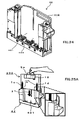
- the cartridge 42 shown in FIG. 24 has a main body portion 410 with a predetermined shape.
- a loading space 401 for loading the container 200 shown in FIG. 15 is provided in the main body portion 410.
- the loading space 401 is blocked in its three directions within the main body portion 410. Namely, there is a situation such that an operator's hand cannot enter into right and left side surfaces and a back surface of the loading space 401.
- a holding-claw mechanism 409 is set at a side of a bottom surface of the loading space 401 and when performing binding process, it holds the binding members 43.
- the holding-claw mechanism 409 operates so as to hold the lowermost binding member 43 or transfer the binding members to a moving mechanism of the binder, not shown, from the lowermost one in turn.
- the container 200 with a single lid structure according to the present invention When the container 200 with a single lid structure according to the present invention is loaded onto the cartridge 42 having such a loading space 401, the container 200 is laded so that it is directed from an upper part of the loading space 401 to a lower part thereof. According to the cartridge 42 shown in FIG. 24 , a mechanism of stopping the container 200 is provided at a middle of the loading space 401.
- a stopper mechanism is provided at the right or left side surface or a back surface of the loading space 401. It is configured that when dropping the container 200 from the upper part of the loading space 401 to a lower part thereof along it, the stopper mechanism stops movement of the container 200.
- a stopper mechanism enables to be realized a structure in which the operator's hand can enter into a lower part of the loading space 401 under the container 200 stopping at a middle thereof, thereby keeping any working space.
- the container-loading procedure is shown, which indicates to contents printed in the display region 15 for an instruction manual in the container-constituting portion 2 of the container 200 shown in FIG. 17 .
- it is designed that the lid-constituting portion 11 and the lid-closing portion 12 are removed by pulling the lid-closing portion 13 positioned toward this side while the container 200 is loaded onto the loading space 401 of the above-mentioned cartridge 42.
- FIG. 25A is a perspective view enlarging an operation procedure No. 1 in the display region 15 for an instruction manual shown in FIG. 17 .
- the operation procedure No. 1 in the display region 15 for an instruction manual a perspective view showing a configuration example of the cartridge 42 shown in FIG. 24 and an illustration when loading the container 200 are displayed.
- a direction for loading the container 200 is shown as an arrow y1.
- an enlarged drawing in which the container 200 is loaded onto the cartridge 42 so that the slit 1d and the like of the container 200 are inserted into predetermined positions of the main body portion 410 of the cartridge 42 is displayed. The user may load the container 200 onto the cartridge 42 according to this enlarged drawing.
- FIG. 25B is a perspective view that enlarges a left side drawing of an operation procedure No. 2 in the display region 15 for an instruction manual shown in FIG. 17 .
- FIG. 25B an illustration when pulling the protrusion 13a of the container 200 loaded in the cartridge 42 toward this side with holding it is displayed.
- a direction for pulling the protrusion 13a is shown as an arrow y2.
- the user may pull the protrusion 13a of the lid-closing portion 13 positioned to this side. This enables the lid-constituting portion 11 and the lid-closing portion 12 to be removed.
- FIG. 25C is a perspective view that enlarges a right side drawing of an operation procedure No. 2 in the display region 15 for an instruction manual shown in FIG. 17 .
- FIG. 25C an illustration in which the protrusion 13a is pulled toward this side with holding it and an illustration in which the binding members 43 fall in parallel from the container 200 loaded in the cartridge 42 are displayed.
- a direction for the binding members to fall in parallel is shown as an arrow y3. The user may operate the protrusion 13a based on this direction.
- FIG. 25D is a perspective view enlarging an operation procedure No. 3 in the display region 15 for an instruction manual shown in FIG. 17 .
- FIG. 25D an illustration when pulling the protrusion 13a so as to rotate toward this side and right side with holding it and an illustration in which the lid-closing portion 13 is released from the lower side of the container 200 loaded in the cartridge 42 are displayed.
- a direction for rotating the lid-closing portion 13 toward this side and right side is shown as an arrow y4.
- the user may operate the protrusion 13a based on this direction.
- the configuration of cuts 12a is provided on a predetermined position of the lid-closing portion 12 away from the engaging portion 13b by a predetermined distance.
- a posture of the lid-closing portion 13 is kept so that it is set to a position which is almost perpendicular to the lid-constituting portion 11 and the lid-closing portion 12.
- the lid-closing portion 13 that is brought into a state kept to such a posture is released from the configuration of cuts 12a (see FIG. 23B ).
- FIG. 25E is a perspective view enlarging an operation procedure No.4 in the display region 15 for an instruction manual shown in FIG. 17 .
- FIG. 25E an illustration in which the container 200 is lifted upward with holding the handle 5e and an illustration in which the container 200 is removed from the cartridge 42 are displayed.
- a direction for removing the container 200 is shown as an arrow y5. The user may operate to remove the container 200 based on this direction.
- the container 200 for loading the consumables is configured by the container material 201 such as coated cardboard for enclosing the binding members 43 (consumables). It is designed that such a container 200 is always kept to contact the binding members 43 with the container 200 on the way of opening (releasing) operation of the lid-constituting portion 11 that protects the bottom thereof.
- the container material 201 such as coated cardboard for enclosing the binding members 43 (consumables). It is designed that such a container 200 is always kept to contact the binding members 43 with the container 200 on the way of opening (releasing) operation of the lid-constituting portion 11 that protects the bottom thereof.
- the slits 1a through 1d and like are provided on both sides of each of the container-constituting portions 1, 2 in a vertical direction thereof, it is possible to make the container-constituting portion 1 largely curved when opening the lid. Accordingly, the opening 6 can be opened in a larger amount thereof, thereby enabling the front operability thereof to be improved as compared by that of the first embodiment.
- any wasted portion after completing the falling-in-parallel of the binding members 43 namely, the lid-closing portion 13 supporting the bottom of the binding members 43 finally is cut and removed by utilizing the configuration of cuts (perforations) 12a. Accordingly, the bottom of the container is opened and the container 200 can wait smoothly upward so that it is capable of loading the binding members 43 onto the cartridge 42 with high reproducibility and high reliability.
- the lid-constituting portion 11 and the like are operated so as to be opened.
- the slits 1a through 1d are previously processed as the configuration of cuts (perforations like a box of sweets).
- any waste portion forming the slits 1a through 1d may have been cut off and removed.
- the present invention is very preferably applicable to a carton containing a plurality of small sized articles, to be handled, such as PET bottles, cans, cigarettes, pencils, and filled parts and a package box for various kinds of electric equipment, an appliance or the like, particularly applicable to a paper-made container (refill) or the like for carrying and filling consumables in a binding system that is provided with a cartridge into which a plurality of the consumables each having a long shape are loaded in a stacked manner.
Landscapes
- Engineering & Computer Science (AREA)
- Mechanical Engineering (AREA)
- Cartons (AREA)
Abstract
Description
- The present invention relates to a container, which is preferably applied to a carton containing a lot of small sized articles, to be handled, such as PET bottles, cans, cigarettes, pencils, and filled parts and a package box for various kinds of electric equipment or the like, particularly, applied to a paper-made refill or the like for carrying and filling consumables in a binding system that is provided with a cartridge into which a plurality of the consumables each having a long shape are loaded in a stacked manner.
- Conventionally, a plurality of small sized articles, to be handled, such as PET bottles, cans, cigarettes, pencils, and filled parts have been often distributed with a desired carton containing them or various kinds of electric equipment or the like have been often distributed with a package box using corrugated cardboard containing them. Such a carton or a package box is made by performing the taking of measurements on carton material or box material with a predetermined size, creating a development of the container, cutting notches into predetermined portions of the developed container and erecting the container by making mountain or valley fold on the carton or box material.
- In accordance with such a container, a packing case for supplement of goods and a method of supplementing the goods for a vending machine using the same have been disclosed in Japanese Patent Application Publication No.
Hei05-04640 - Further, a package box has been disclosed in Japanese Patent Application Publication No.
2001-02057 - Further, a package with a dispenser has been disclosed in Japanese Patent Application Publication No.
2005-53555 - By taking such a container configuration, it is capable of easily removing the articles one by one from the package without any complicated works, thereby enabling workability to be improved.
- An opening assist for a dispensing carton has been also disclosed in Japanese Patent Application Publication No.
2005-53584 - According to the conventional containers each having the opening, however, there are problems as follows.
- (i) As disclosed in Japanese Patent Application Publication No.
Hei05-04640 2001-02057 2005-53555 2005-53584 Hei05-04640 2001-02057 2005-53555 2005-53584 - (ii) Particularly, if a plurality of small articles each having a complicated shape are loaded onto the automatic machine or the like when the container with the dispenser disclosed in any of Japanese Patent Application Publication No.
Hei05-04640 2001-02057 2005-53555 2005-53584 - (iii) If the consumables are stacked in a container calling, for example, the refill and they are loaded from the refill into a cartridge of the binding system when the consumables are loaded from inside of the refill into the cartridge by free fall thereof, it is confirmed that any consumables may be inclined on the way for falling so that they are caught because it is impossible to control a posture of the falling consumable. Accordingly, a case may occur where they cannot be properly staked in the cartridge so that any poor separation of the consumables is generated.
- (iv) By the way, it is conceivable how to tie up the stacked consumables with a string to keep the stacked condition thereof and cut the string after they are loaded onto the cartridge. When, however, adopting this method, there is such a problem that a predetermined shape thereof may be not kept if a shock or the like is applied to the stacked consumables from outside. Accordingly, under the existing circumstances, both problems of keeping a box shape and avoiding the free falling of the consumables cannot be solved.
- This invention solves the above-mentioned problems and has an object of providing a container that is capable of loading any contents onto a cassette for containing articles and the like with good reproducibility from inside of the container and is suitably applied to a paper-made refill, which is applicable to a vending machine, various kinds of parts cassettes or the like.
- In order to solve the above-mentioned problems, a container according to the present invention in which one of container-constituting surfaces forms an opening with a predetermined size, is provided with, if two constituting surfaces standing facing each other across the opening are supposed as first and second constituting surfaces, at least a first folding surface that makes a mountain fold on the first constituting surface, the first folding surface having a width extending beyond the opening, and a second folding surface that makes a mountain fold on the first folding surface to engage the second constituting surface. The container is characterized in that when opening the opening, the second folding surface disengages the second constituting surface and the first folding surface is folded back to a position so that it becomes the same wall surface as that of the first constituting surface.
- In the container according to the present invention, when the contents are brought out with an opening side thereof facing downward, a side surface of any one of the contents contacts the continued wall surface formed by the wall surface constituted of the first constituting surface and the first folding surface along it. Accordingly, when loading the contents onto any desired cassette or the like for containing the articles, it is possible to control a posture of the contents each falling in parallel along the wall surface of the first folding surface, which is continuous with the wall surface of the first constituting surface. This enables the contents to be loaded onto the cartridge for containing the articles and the like with good reproducibility from inside of the container. Further, it is possible to apply the container suitably to a paper-made refill or the like, which is applicable to a vending machine, various kinds of parts cassettes or the like.
-
- [
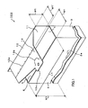
FIG. 1 ] is a conceptual diagram showing a configuration example of acontainer 100 as an embodiment according to the present invention. - [
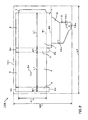
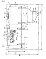
FIG. 2 ] is a diagram showing an example of measurements incontainer material 101. - [
FIG. 3 ] is an erecting-process diagram showing a lid-closing example (part one thereof) of thecontainer 100 according to a first embodiment. - [
FIG. 4 ] is the erecting-process diagram showing the lid-closing example (part two thereof) of thecontainer 100. - [
FIG. 5 ] is the erecting-process diagram showing the lid-closing example (part three thereof) of thecontainer 100. - [
FIG. 6A ] is the erecting-process diagram showing the lid-closing example (part four thereof) of thecontainer 100. - [
FIG. 6B ] is an enlarged diagram showing a lid-closing portion, which is illustrated in an ellipse by the dashed line, in thecontainer 100 shown inFIG. 6A . - [
FIG. 7 ] is a perspective view of thecontainer 100 showing an outline example thereof when completing closing the lid. - [
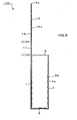
FIG. 8 ] is a perspective view of thecontainer 100 showing a configuration example thereof when loading it into theautomatic machine 400 or the like. - [
FIG. 9 ] is a perspective view showing a loaded example of thecontainer 100. - [
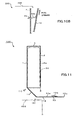
FIG. 10A ] is a cross sectional view of thecontainer 100 showing a lid-opening example thereof (part one thereof). - [
FIG. 10B ] is an enlarged view of a lid-opening portion of thecontainer 100 shown inFIG. 10A . - [
FIG. 11 ] is a cross sectional view of thecontainer 100 showing the lid-opening example thereof (part two thereof). - [
FIG. 12 ] is a cross sectional view of thecontainer 100 showing the lid-opening example thereof (part three thereof). - [
FIG. 13 ] is a cross sectional view of thecontainer 100 showing the lid-opening example thereof (part four thereof). - [
FIG. 14 ] is a cross sectional view of thecontainer 100 showing the lid-opening example thereof (part five thereof). - [
FIG. 15 ] is a perspective view of acontainer 200 for loading the consumables as a second embodiment showing a configuration example thereof. - [
FIG. 16A ] is a top plan view of a bindingmember 43, to be contained in thecontainer 200 shown inFIG. 15 , showing a configuration example thereof. - [
FIG. 16B ] is a front view of the bindingmember 43 showing a configuration example thereof, which is seen from a direction of an arrow B ofFIG. 16A . - [
FIG. 16C ] is a cross sectional view, taken along arrows C-C, of the bindingmembers 43 showing a stacked example thereof, which is seen from a direction of the arrow B ofFIG. 16A . - [
FIG. 17 ] is a diagram showing an example of measurements incontainer material 201. - [
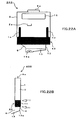
FIG. 18A ] is a front view of thecontainer 200 showing a lid-opening example thereof (part one thereof). - [
FIG. 18B ] is a side view of thecontainer 200, shown inFIG. 18A , showing a configuration example thereof. - [
FIG. 19A ] is a front view of thecontainer 200 showing a lid-opening example thereof (part two thereof). - [
FIG. 19B ] is a side view of thecontainer 200, shown inFIG. 19A , showing a configuration example thereof when opening the lid. - [
FIG. 20A ] is a front view of thecontainer 200 showing a lid-opening example thereof (part three thereof). - [
FIG. 20B ] is a side view of thecontainer 200, shown inFIG. 20A , showing a configuration example thereof when opening the lid. - [
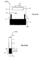
FIG. 21A ] is a front view of thecontainer 200 showing a lid-opening example thereof (part four thereof). - [
FIG. 21B ] is a side view of thecontainer 200, shown inFIG. 21A , showing a configuration example thereof when opening the lid. - [
FIG. 22A ] is a front view of thecontainer 200 showing a lid-opening example thereof (part five thereof). - [
FIG. 22B ] is a side view of thecontainer 200, shown inFIG. 22A , showing a configuration example thereof when opening the lid. - [
FIG. 23A ] is a front view of thecontainer 200 showing a lid-opening example thereof (part six thereof). - [
FIG. 23B ] is a side view of thecontainer 200, shown inFIG. 23A , showing a configuration example thereof when opening the lid. - [
FIG. 24 ] is a perspective view of acartridge 42 showing a configuration example thereof. - [
FIG. 25A ] is a perspective view of thecontainer 200 showing a loaded example thereof (part one thereof). - [
FIG. 25B ] is a perspective view of thecontainer 200 showing a loaded example thereof (part two thereof). - [
FIG. 25C ] is a perspective view of thecontainer 200 showing a loaded example thereof (part three thereof). - [
FIG. 25D ] is a perspective view of thecontainer 200 showing a loaded example thereof (part four thereof). - [
FIG. 25E ] is a perspective view of thecontainer 200 showing a loaded example thereof (part five thereof). - The following will describe embodiments of a container according to the present invention with reference to drawings.
- The embodiment of the
container 100 according to the invention, shown inFIG. 1 , is applicable to a package box for a plurality of small sized articles, to be handled, such as PET bottles, cans, cigarettes, pencils, and filled parts and for various kinds of electric equipment or the like. Particularly, thiscontainer 100 is applicable to a paper-made refill or the like for carrying and loading consumables, for which any contents in which a plurality of consumables each having long shape are stacked are handled in a binding system. In thecontainer 100, one of container-constituting surfaces forms anopening 6 with a predetermined size. In other words, one of the six surfaces constituting thecontainer 100 is opened. The following will describe the container-constituting surface as a container-constituting portion (part). - A size of the
entire container 100 is constituted of a height H1, a length L1 and a width W1. A size of theopening 6 is obtained by multiplying L1 by W1. In thecontainer 100, if two container-constituting portions standing facing each other across theopening 6 are supposed as first container-constitutingportion 1 and second container-constitutingportion 2, a first lid-constitutingportion 11 constituting a first folding surface is unfolded onto the container-constitutingportion 1 as a side wall. - In these embodiments, the lid-constituting
portion 11 extends continuously from a side prescribing the length L1 of the container-constitutingportion 1 up to a length similar to the width W1 of theopening 6. The lid-constitutingportion 11 has a width (length) extending beyond theopening 6 of L1 multiplied by W1. The lid-constitutingportion 11 folds and makes a mountain fold on the container-constitutingportion 1 on the basis of outside of the container. - A lid-closing
portion 12 and a lid-closing portion 13 (separable portion), which constitute a second folding surface, are unfolded onto the lid-constitutingportion 11. The lid-closingportion 12 and the lid-closingportion 13 make a mountain fold on the lid-constitutingportion 11. The lid-closingportion 13 is formed so that it engages the container-constitutingportion 2. In these embodiments, lid-closingportion 12 extends continuously from a side prescribing the length of the lid-constitutingportion 11 up to a width (length) W1' that is almost similar to the width W1 of theopening 6. The lid-closingportion 12 has a trapezoid such that both sides are cut and has an area less than that of the rectangular of the lid-constitutingportion 11. The lid-closingportion 12 makes a mountain fold on the lid-constitutingportion 11. - The separable lid-closing
portion 13 is unfolded onto the lid-closingportion 12. In these embodiments, the lid-closingportion 13 extends continuously from a side prescribing the width of the lid-closingportion 12 up to a predetermined length. The lid-closingportion 13 has a predetermined shape and a size and is connected to the lid-closingportion 12 through a configuration ofcuts 12a on the same plane. The lid-closingportion 13 is shaped so as to become a flat trapezoid with a protrusion 13a. The protrusion 13a constitutes a grip. - In these embodiments, an engaged
portion 2a is provided in the container-constitutingportion 2 at its predetermined position and an engagingportion 13b is provided in the lid-closingportion 13 at its predetermined position. The engagedportion 2a is formed by, for example, cutting a groove forming a slit at a position of the container-constitutingportion 2, which lies slightly toward a side of the container-constitutingportion 3 away from middle thereof. The engagingportion 13b is formed by cutting a groove in semicircle at a lower position of the protrusion 13a. In these embodiments, when closing theopening 6, to the semicircular engagingportion 13b of the lid-closingportion 13 is inserted into (engages) the engagedportion 2a forming the slit of the container-constitutingportion 2. - For example, when opening the
opening 6, the engagingportion 13b of the lid-closingportion 13 first disengages the engagedportion 2a of the container-constitutingportion 2. Next, the lid-closingportion 13 enters a state of disengaging the container-constitutingportion 2. Further, the lid-constitutingportion 11 is folded back to a position so that it becomes the same wall surface as that of the container-constitutingportion 1. Thereafter, the lid-closingportion 13 is cut off. - Regarding other container-constituting portions, container-constituting
portions portions portion 3 is walled so that it constitutes a side wall. The container-constitutingportion 4 is walled so that it constitutes the other side wall. On a bottom side shown inFIG. 1 , a container-constitutingportion 5 is walled. Thus, thecontainer 100 having a single lid structure is configured. - Configuring such a
container 100 allows contents of thecontainer 100 to be covered by the container-constitutingportions portion 11 and other container-constitutingportions opening 6 has closed. This also enables a predetermined shape of each of the contents to be kept. Further, if the contents are dropped and contained into a desired cassette or the like for containing articles while directing theopening 6 downward, the lid-closingportion 12, a posture of which is kept to a position almost perpendicular to the lid-constitutingportion 11, can support the contents. The lid-closingportion 13 may be cut off under a condition such that weights of the contents are applied to the lid-closingportion 12. - The following will describe a method of manufacturing the
container 100 with reference toFIG. 2 . When manufacturing thecontainer 100 as shown inFIG. 1 , for example, acontainer material 101 having a size like an exploded example of thecontainer 100 shown inFIG. 2 is prepared. As thecontainer material 101, for example, coated cardboard with paper quality of 350 g/m2 is used. A development may be drawn so that a coated surface thereof forms an inside of thecontainer 100. This is because the parts contained in thecontainer 100 are easy to slide inside the container and are easy to be loaded into an automatic machine or the like when loading the parts thereinto. - The coated cardboard has a size constituted of a vertical length W0 and a horizontal length L0. Though depending on a finished measurement of the
container 100, the vertical one W0 may be almost (5 through 7)W1+ H1 and the horizontal one L0 may be almost 2L1+2W1+a margin for connection or more. Thecontainer material 101 is not limited to the coated cardboard but corrugated cardboard, plastic panel with a predetermined thickness may be used therefor according to containing uses. If a container which can be used repeatedly again and again is formed, the container using the plastic panel can be increased in its used times more than that of a paper container. - According to a developed example of the
container 100 shown inFIG. 2 , the container-constitutingportions portions margin 7 for connection of height H1 are drawn above almost a half of thecontainer material 101. The container-constitutingportions parts margin 7 for connection are continuously arranged so that they are aligned horizontally. - Further, the lid-constituting
portion 11 of length L1 and width W1, the lid-closingportion 12, the trapezoidal lid-closing (separable)portion 13, and the protrusion 13a forming the grip are drawn below the container-constitutingportion 1. These lid-constitutingportion 11, lid-closingportion 12, lid-closing (separable)portion 13 and the protrusion 13a are arranged at positions that are continuous with the container-constitutingportion 1. The engagedportion 2a is drawn in the container-constitutingportion 2 and then is opened. - In these embodiments, a perforation is performed on a borderline of the lid-closing
portions cuts 12a is formed. In the figure, #1 and #2 depict folding lines. Thefolding line # 1 forms a borderline of the container-constitutingportion 1 and the lid-constitutingportion 11 and thefolding line # 2 forms a borderline of the lid-constitutingportion 11 and the lid-closingportion 12. - Further, regarding a shape of a bottom of the
container 100, for example, if opening it into two parts as portmenteau, a container-constitutingportion 5 of length L next to the container-constitutingportion 2, a container-constituting piece 5a of length W1 next to the container-constitutingportion 3, a container-constitutingportion 5 of length L next to the container-constitutingportion 1, and a container-constituting piece 5b of length W1 next to the container-constitutingportion 4 are drawn. - It is to be noted that, in the figure, a container-constituting piece 8a may be disposed on a position under the container-constituting
portion 3 shown by alternate long and two short dashes line and a container-constituting piece 8b may be disposed on a position under the container-constitutingportion 4 shown thereby. The container-constituting piece 8a makes a mountain fold on the container-constitutingportion 3 next to the container-constitutingportion 1. The container-constituting piece 8b makes a mountain fold on the container-constitutingportion 4 next to the container-constitutingportion 2. Disposition of the container-constituting pieces 8a, 8b enables the strength of theentire container 100 to be increased. Of course, the disposition of the container-constituting pieces 8a, 8b may be omitted. - In the figure, broken lines other than the
folding lines # 1 and #2 show positions for folding and making mountain folds thereon. In these embodiments, when cutting thecontainer material 100 along solid lines by using a cutter, scissors or the like, a developed shape of thecontainer 100 is completed as shown inFIG. 1 . Further, when erecting it by folding and making mountain folds along the above-mentioned broken lines, thecontainer 100 as shown inFIG. 7 can be completed. - The following will describe a lid-closing example of the
container 100 according to a first embodiment with reference to erecting-process diagrams ofFIGS. 3 ,4 ,5 ,6A and 6B . Triangle marks (i) and (ii) in white shown inFIGS. 3 through 5 are all folding positions (positions of thefolding lines # 1 and #2). - First, the
container 100 shown inFIG. 3 is prepared. In order to obtain thecontainer 100, each of the container-constitutingportions 1 through 4 and themargin 7 for connection in the developed form shown inFIG. 2 folds and makes a mountain fold to form the container-constitutingportions 1 through 4 as a box. The container-constitutingportion 4 and themargin 7 for connection are connected with each other by an adhesive, a staple or the like. The container-constituting pieces 5a, 5b to build up a bottom surface are then folded inwardly in advance and the container-constitutingportions 5 fold and make mountain folds onto the container-constituting pieces 5a, 5b. It is constituted that butt portions of the container-constitutingportions 5 are stuck by a tape or the like. - Thus, as shown in
FIG. 3 , thecontainer 100 is obtained such that the lid-constitutingportions portion 13 and the protrusion 13a forming the grip extend upwards in succession from the container-constitutingportion 1 and theopening 6 is defined. - In this embodiment,
articles 30 are contained into thecontainer 100 from theopening 6 shown inFIG. 3 . Thearticles 30 are, for example, a plurality of small sized ones, to be handled, such as PET bottles, cans, cigarettes, pencils, and filled parts, various kinds of electric equipment or the like. - Next, as shown in
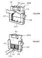
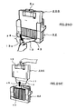
FIG. 4 , theopening 6 is closed. In this moment, the lid-constitutingportion 11 folds and makes mountain folds on the folding positions (i). Further, as shown inFIG. 5 , the lid-closingportion 12 folds and makes mountain folds on the folding positions (ii) so that the lid-closingportion 12 covers over theopening 6. - The lid-constituting
portion 11 and the lid-closingportion 12 then wraps a corner of theopening 6 on the folding position (ii) shown inFIG. 5 . Further, the lid-closingportions portion 2. As shown inFIG. 6A , the engagingportion 13b then engages the engagedportion 2a. In this embodiment, the semicircular engagingportion 13b is inserted into the engagedportion 2a, in the enlarged sectional view ofFIG. 6B , from a front surface of the container-constitutingportion 2 to a rear surface thereof. A forward end of the engagingportion 13b catches the engagedportion 2a so that the lid-closingportion 13 is locked. Of course, an engaging method is not limited thereto; a double-sided tape may stick the protrusion 13a forming the gripe and the container-constitutingportion 2. Thus, theopening 6 in thecontainer 100 can be firmly closed (seeFIG. 7 ). - According to an outline example, shown in
FIG. 7 , of thecontainer 100 when completing closing the lid, it is possible to fix the lid-closingportion 13 on the container-constitutingportion 1 exactly. Even if the container-constitutingportion 5 is directed upward and a single lid structure part is directed downward, it is also possible to maintain the closed state of theopening 6 steadfastly as shown inFIG. 7 . Configuring such acontainer 100 allows the articles, which are easy to be separated, to be handled with ease by the container-constitutingportions 1 through 5, the lid-constitutingportion 11, and the lid-closingportions - When loading the
container 100 onto an automatic machine, a power tool or the like, the protrusion 13a forming the grip, which extends to this side, is pulled while thecontainer 100 is loaded onto the automatic machine, the power tool or the like. This enables the lid-constitutingportion 11 and the lid-closingportions - Next, the following will describe a loaded example of the
container 100 onto anautomatic machine 400 or the like with reference toFIGS. 8 and9 . In this embodiment, thecontainer 100 is loaded onto theautomatic machine 400 or the like with a side of its lid-closing portion being directed downward. - The
automatic machine 400 shown inFIG. 8 is a vending machine, a binding machine, various kinds of power tools or the like and has aloading space 401 for loading thecontainer 100 as shown inFIG. 7 . Theloading space 401 is blocked in its three directions. Namely, there is a situation such that an operator's hand cannot enter into right and left side surfaces and a back surface of theloading space 401. A side of a bottom surface of theloading space 401 becomes parts-loading space 402, which has often such a structure that an operator's hand cannot enter into it depending on a type ofautomatic machine 400. - When the
container 100 with a single lid structure according to the present invention is loaded onto theautomatic machine 400 having such aloading space 401, thecontainer 100 is laded so that it is directed from an upper part of theloading space 401 to a lower part thereof or from a front surface thereof to a back surface thereof. - According to the loaded example of the
container 100 shown inFIG. 9 , a mechanism of stopping thecontainer 100 at a middle of theloading space 401 is provided. For example, a stopper mechanism, not shown, is provided at the right or left side surface or a back surface of theloading space 401. It is configured that when dropping thecontainer 100 from the upper part of theloading space 401 to a lower part thereof along it, the stopper mechanism stops movement of thecontainer 100. Such a mechanism enables to be realized a structure in which the operator's hand can enter into a lower part of theloading space 401 under thecontainer 100 stopping at a middle thereof, thereby keeping any working space. - In this embodiment, it is configured that the lid-constituting
portions 11 and the lid-closingportion 12 are opened by pulling the lid-closingportion 13 positioned at this side under a situation where thecontainer 100 is loaded onto the above-mentionedloading space 401. - Next, the following will describe a lid-opening example of the
container 100 with reference toFIGS. 10A and10B ,11 ,12 ,13 and 14 . In this embodiment, a case is illustrated where thecontainer 100 having the single lid structure according to the invention is loaded onto theautomatic machine 400 shown inFIG. 8 and thearticles 30 are loaded thereto, and the configuration ofcuts 12a is provided at a predetermined position of the lid-closingportion 12, which is away from the engagingportion 13b of the lid-closingportion 13 by a predetermined distance. A posture of the lid-closingportion 12 is kept at a position that is almost perpendicular to the lid-constitutingportion 11. Then, the following will describe a case where the side of the engagingportion 13b of the lid-closingportion 13 while its posture is maintained is cut off from the configuration ofcuts 12a. It is to be noted that inFIGS. 10A and10B ,11 ,12 ,13 and 14 , as for theautomatic machine 400, only the parts-loading space 402 is shown by alternate long and two short dashes line and a case where thearticles 30 are loaded onto the parts-loading space 402 is illustrated. - First, the
container 100 is loaded onto theautomatic machine 400 as shown inFIG. 9 . Next, by taking the lid-closingportion 13 out of the container-constitutingportion 2 as shown inFIG. 10A , theopening 6 is opened. In this moment, a user may pull the lid-closingportion 13 toward this side while the protrusion 13a (grip) thereof is held and pulled tight upward. This allows the engagingportion 13b to disengage the engagedportion 2a. According toFIG. 10B where this portion is enlarged, the engagingportion 13b is pulled out of the engaged portion (slit portion) 2a so that the engagedportion 2a and the engagingportion 13b are separated from each other. - Next, the
container 100 is operated so that the lid-constitutingportion 11 is bent back in a direction of making valley folds based on the folding position (i) shown inFIG. 11 . In this moment, a user moves the lid-constitutingportion 11 backward while he is pulling the lid-closingportion 13 toward this side, thereby opening theopening 6. According to this opening operation, thearticles 30 contained in thecontainer 100 are barely held by a part of the lid-constitutingportion 11 so as to become a situation just before thearticles 30 drop. - Then, the bending-back operation in a direction of making valley folds based on the folding position (i) as shown in
FIG. 12 goes on. By this operation, the lid-constitutingportion 11 and the container-constitutingportion 1 form the same wall surface. In this moment, the user moves the lid-constitutingportion 11 backward while he is pulling the lid-closingportion 13 toward this side, thereby opening theopening 6. By this continued opening-operation, thearticles 30 contained in thecontainer 100 drop (fall in parallel) along a wall surface of the lid-constitutingportion 11. In this moment, along a continuous wall surface constituted of a wall surface formed by the container-constitutingportion 1 and a wall surface formed by the lid-constitutingportion 11, a side surface of each of the articles contacts it. By such a falling-in-parallel, thearticles 30 become a state so as to hold them by the lid-closingportion 12 on the parts-loading space 402. - The lid-closing
portion 13 is then separated from the lid-closingportion 12 through a borderline of the configuration ofcuts 12a shown inFIG. 13 . In this moment, the user operates to pull the protrusion 13a of the lid-closingportion 13 strongly toward this side with him holding it. By this operation, it is possible to separate from the configuration ofcuts 12a only the lid-closingportion 13 of the second folding surface supporting thearticles 30. Thecontainer 100 is then pulled upward. In this moment, the lid-closingportion 12 is bent back based on the folding position (ii) that is almost perpendicular from the lid-closingportion 12, a posture of which is kept to the lid-constitutingportion 11. By this bending operation, it is possible to from the same wall surface constituted of the lid-closingportion 12 in addition to the container-constitutingportion 1 and the lid-constitutingportion 11. This enables a falling-in-parallel posture of each of the articles to be further controlled with the continuous wall surface constituted of the container-constitutingportion 1, the lid-constitutingportion 11 and the lid-closingportion 12. - According to the
container 100 shown inFIG. 14 , the lid-closingportion 12 following the container-constitutingportion 1 and the lid-constitutingportion 11 form the same wall surface so that they wait with them contacting a side surface of each of thearticles 30. This enables thearticles 30 to be loaded onto theautomatic machine 400. - Thus, according to the
container 100 as the first embodiment, when taking thearticles 30 outside while a side of theopening 6 is directed downward, the side surface of each of thearticles 30 is formed as to contact the continuous wall surface constituted of the wall surface formed by the container-constitutingportion 1 and the wall surface formed by the lid-constitutingportion 11 along it. This enables the falling-in-parallel posture of each of thearticles 30 to be controlled so as to go along the wall surface of the lid-constitutingportion 11 that is continuous from the wall surface of the container-constitutingportion 1 when loading thearticles 30 onto the cassette or the like for containing the articles. - Accordingly, it is capable of taking the
articles 30 out of inside of thecontainer 100 with good reproducibility toward a downward direction while the side of theopening 6 is directed downward. This enables thecontainer 100 to be suitably applied to a paper-made refill or the like, which is applicable to a vending machine, various kinds of parts cassettes or the like. Particularly, thiscontainer 100 is suitably applicable to a refill for loading the consumables onto the binding system. - The following will describe a configuration example of a
container 200 for loading consumables according to a second embodiment with reference toFIG. 15 . According to thecontainer 200 shown inFIG. 15 , the single lid structure of thecontainer 100 according to the invention is also provided and plural binding members as one example of thearticles 30 are handled so as to contain them therein (seeFIGS. 16A through 16C ). - In this embodiment, slits 1a, 1b for assisting opening or closing and positioning are provided in a container-constituting
portion 1 on a vertical direction thereof and slits 1c, 1d for assisting opening and closing are provided in a container-constitutingportion 2 on a vertical direction thereof. The slits 1a, 1b are provided at right and left two positions on the same plane of the container-constitutingportion 1. Similarly, the slits 1c, 1d are provided at right and left two positions on the same plane of the container-constitutingportion 2. Length of each of the slits 1a through 1d is 11. - The
length 11 is set so as to be almost a half of a height H of thecontainer 200. This is figured out to move the lid-constitutingportion 11 easily further back and forth. It is possible to open theopening 6 wider than that of the first embodiment, which is easy to load thearticles 30 in the container onto the cartridge or the like. - In this embodiment, it is designed that a part of the
container 200 that is positioned at an opposite side of a part thereof in which the single lid structure is arranged is a container-constitutingportion 5c and the container-constitutingportion 5c is provided with a handle 5e as shown inFIG. 17 . It is designed that thecontainer 200 is easy to be carried. - In this embodiment, a
display region 15 for an instruction manual is provided at an upper portion of the container-constitutingportion 2 and any instruction procedure when loading thecontainer 200 are printed thereon. The user may operate the lid-closingportions 13 and 12 (tab) or the like based on this instruction procedure. Further, it is designed that a part of the container-constitutingportion 1, which is positioned at an opposite side of a part thereof in which the single lid structure is arranged, is a container-constituting portion 5g. The container-constituting portion 5g is provided with an opening 5f for the handle and anengaging piece 5h. The container-constitutingportion 5c is provided with a slit 5i for being engaged with the engaging piece (seeFIG. 17 ). It is to be noted that names and signs similar to those of the first embodiment have the same functions as those thereof, an explanation of which will be omitted. - Here, the binding member(s) 43 that can be contained in the
container 200 will be described with reference toFIGS. 16A through 16C . The bindingmember 43 shown inFIG. 16A constitutes an example of thearticles 30 and plural kinds thereof are manufactured according to thicknesses of bundles of paper to be bound in a binder. The bindingmember 43 is formed by utilizing a die-forming device. For example, the bindingmember 43 is made of a resin-molding product that is constituted of abackbone portion 43a having a length that conforms to a size of a standard size paper (for example, A size) andring portions 43b that are arranged with a fixed space, each becoming a ring shape. The bindingmembers 43 are contained in thecontainer 200 in groups of plural pieces thereof for every kind. - It is configured that as shown in
FIG. 16B , eachring portion 43b is split into three parts which are an arc shapedring part 43c that is connected with thebackbone portion 43a and arc shapedring parts backbone portion 43a has a shape in which a base is a straight line and an upper middle is convex. It is to be noted that as shown inFIGS. 16A and16B , the arc shapedring part 43c that becomes apredetermined ring portion 43b is provided with a projectedpin 43f. Thering portion 43c is provided with a housing hole, not shown, corresponding to thepin 43f on a side thereof that is opposite to the side at which thepin 43f is provided. - According to the stacked binding
members 43 shown inFIG. 16C , it is configured that pluralbinding members 43 are stacked by inserting eachpin 43f into each housing hole while both ends of each of the arc shapedring parts ring portion 43b shown inFIGS. 16A and16B are aligned on almost a straight line. This enables the bindingmembers 43 to be contained in thecontainer 200 shown inFIG. 15 in groups of plural pieces thereof for every kind. - The following will describe a method of manufacturing the
container 200 with reference to a developed example of thecontainer 200 shown inFIG. 17 . In this example, by figuring out how to fold it from one piece ofcontainer material 201, thecontainer 200 having a simple structure and a minimum configuration without using another material can be presented. - If the
container 200 as shown inFIG. 15 is manufactured, thecontainer material 201 having, for example, a size shown inFIG. 17 is prepared. As thecontainer material 201, coated cardboard with paper quality of 350 g/m2 is used, similar to the first embodiment. In this embodiment, a development may be also drawn so that a coated surface thereof forms an inside of thecontainer 200. The reason therefor has been described in the first embodiment, the description of which will be omitted. - The coated cardboard has a size constituted of a vertical length W0' and a horizontal length L0. In this embodiment, the
container material 201 that is larger than that of the first embodiment is prepared to form the handle 5e and the container-constitutingportion 5c. Though depending on a finished measurement of thecontainer 200, the vertical length W0' may be almost (5 through 7)W1+ H1 or more and the horizontal one L0 may be almost 2L1+2W1+a margin for connection or more. Thecontainer material 201 is not limited to the coated cardboard but the ones described in the first embodiment may be used therefor. - The
container material 201 shown inFIG. 17 is drawn, the slits 1a, 1b are provided in the container-constitutingportion 1 and the slits 1c, 1d are provided in the container-constitutingportion 2. In this moment, triangles are drawn so that they project from both sides of the lid-constitutingportion 11. When proving with these slits 1a, 1b, base area of the lid-constitutingportion 11 is reduced while the base area may be complemented by these triangles. - In this embodiment, the handle 5e is drawn on the container-constituting
portion 5c. The container-constitutingportion 5c is continuously extended from a side of the container-constitutingportion 2, which is opposite to the side thereof in which the single lid structure is arranged. The opening (slit) 5f for the handle draws the container-constituting portion 5g. The container-constituting portion 5g is continuously extended from a side of the container-constitutingportion 1, which is opposite to the side thereof in which the single lid structure is arranged. Thus, when erecting the container, by inserting the handle 5e into the opening 5f, the container-constitutingportions 5c, 5g become double structure, thereby obtaining strength of thecontainer 200. - The engaging
piece 5h is provided on the container-constituting portion 5g in addition to the opening 5f for the handle and the slit 5i for being engaged with the engaging piece is provided on the container-constitutingportion 5c. This enables the container-constituting portion 5g to be held onto the slit 5i by inserting the engagingpiece 5h into the slit 5i when erecting the container. The slit constituting the engagedportion 2a is provided on the container-constitutingportion 2. It is configured so that the engagingportion 13b can be held onto the engagedportion 2a when erecting the container. - Further, a circular window 5d for checking color or the like of the contents is arranged on the container-constituting
portion 5c. Other parts thereof are similar to those ofFIG. 2 , the description of which will be omitted. Thus, a development of thecontainer 200 is constituted and cutting and folding it allows thecontainer 200 shown inFIG. 15 to be completed. This enables thecontainer 200 for loading the consumables, which has a base shape that allows the bindingmembers 43 to fall in parallel and the configuration ofcuts 12a, to be constructed. The lid-constitutingportion 11 having a configuration of one base is also provided so that the base shape of the lid-constitutingportion 11 may prevent any binding members (consumables) 43 from being deformed. - Next, the following will describe a lid-opening example of the
container 200 with reference toFIGS. 18A, 18B ,19A, 19B ,20A, 20B ,21A, 21B ,22A, 22B ,23A and 23B . In this embodiment, a case is illustrated where the engagingportion 13b of the lid-closingportion 13 is disengaged while a part in which the single lid structure is arranged is directed downward so that theopening 6 is opened. - The plural
binding members 43 shown inFIG. 16A are contained in thecontainer 200 shown inFIG. 18A with them being stacked. In this embodiment, the semicircular engagingportion 13b of the lid-closingportion 13 is inserted into the engagedportion 2a of the container-constitutingportion 2 so that they are sealed. It is designed that thecontainer 200 is carried with holding the handle 5e shown inFIG. 18B . - First, as shown in
FIG. 19A , the lid-closingportion 13 is taken out of the container-constitutingportion 2 shown inFIG. 18A and the lid-closingportion 13 is pulled toward this side. For example, the user pulls the lid-closingportion 13 toward this side while he holds the protrusion 13a (grip) thereof and pulls it tight upward. This allows the engagingportion 13b to disengage the engagedportion 2a (seeFIG. 10B ). In this moment, by the slits 1a, not shown, 1b, not shown, 1c, 1d, which are provided along a vertical direction, and the like, the container-constitutingportion 1 is made curved larger than that of the first embodiment so that theopening 6 may be opened by a larger amount thereof (seeFIG. 19B ). - Next, the
container 200 is operated so that the lid-constitutingportion 11 is bent back in a direction of making valley folds based on the folding position (i) shown inFIG. 19B . In this moment, the user moves the lid-constitutingportion 11 backward while he is pulling the lid-closingportion 13 toward this side, thereby opening theopening 6. According to this opening operation, the bindingmembers 43 contained in thecontainer 200 shown inFIG. 20A are barely held by a part of the lid-constitutingportion 11 shown inFIG. 20B so as to become a situation just before thebinding members 43 drop. - Then, the bending-back in a direction of making valley folds based on the folding positions (i), (ii) as shown in
FIG. 20B goes on so that the lid-constitutingportion 11 and the container-constitutingportion 1 form the same wall surface. In this moment, the user moves the lid-constitutingportion 11 backward while he is pulling the lid-closingportion 13 toward this side, thereby opening theopening 6. By this continued opening-operation, as shown inFIG. 21B , the bindingmembers 43 contained in thecontainer 200 drop (fall in parallel) along a wall surface of the lid-constituting portion 11 (conventional free fall area). - This free fall area occurs because a length of the groove on which the
container 200 is inserted into thecartridge 42 is set to be made small in regard to an object to pack the binding members (stacked consumables) 43 by paper-made package as simple as possible and maintain its box shape. The falling-in-parallel posture of the bindingmembers 43 is controlled in this free fall area. By this control, the bindingmembers 43 contained in thecontainer 200 shown inFIG. 21A become brought into a state where about a quarter thereof is exploded below from theopening 6. - The lid-closing
portion 12 is bent back based on the configuration ofcuts 12a as shown inFIG. 22B . This enables the falling-in-parallel posture of the bindingmembers 43 to be further controlled by the continuous wall surface constituted of the container-constitutingportion 1, the lid-constitutingportion 11 and the lid-closingportion 12. In this embodiment, along a continuous wall surface constituted of a wall surface formed by the container-constitutingportion 1, a wall surface formed by the lid-constitutingportion 11 and a wall surface formed by the lid-closingportion 12, a side surface of each of the articles contacts it. By such a contact, the bindingmembers 43 contained in thecontainer 200 shown inFIG. 21A further fall in parallel as shown inFIG. 22A . By such a falling-in-parallel, as shown inFIG. 23B , the bindingmembers 43 are brought into a state where they are hold by the lid-closingportion 13. - In this embodiment, the configuration of
cuts 12a is positioned at back side, which is different from the first embodiment, and the lid-closingportions cuts 12a. Thus, the bindingmembers 43 contained in thecontainer 200 shown inFIG. 23A become brought into a state where about a half thereof is exploded below from theopening 6. - The lid-closing
portion 13 is then separated from the lid-closingportion 12 from a borderline of the configuration ofcuts 12a shown inFIG. 23B . In this moment, the user operates to pull the protrusion 13a of the lid-closingportion 13 strongly toward this side with him holding it. This enables only the lid-closingportion 13 of the second folding surface supporting the bindingmembers 43 to be separated from the configuration ofcuts 12a. It is possible to remove the lid-closingportion 13 from the bottom surface of the binding members 43 (seeFIG. 23A ). Thecontainer 200 is then lifted upward. - According to the
container 200 shown inFIG. 23B , the container-constitutingportion 1, the lid-constitutingportion 11 and the lid-closingportion 12 form the same wall surface so that they wait with them contacting a side surface of each of the bindingmembers 43. This enables the bindingmembers 43 to be easily loaded onto the cartridge of the binder or the like. - The following will describe a case where the
cartridge 42 is used instead of the automatic machine for loading the container. Thecartridge 42 shown inFIG. 24 has amain body portion 410 with a predetermined shape. Aloading space 401 for loading thecontainer 200 shown inFIG. 15 is provided in themain body portion 410. - The
loading space 401 is blocked in its three directions within themain body portion 410. Namely, there is a situation such that an operator's hand cannot enter into right and left side surfaces and a back surface of theloading space 401. A holding-claw mechanism 409 is set at a side of a bottom surface of theloading space 401 and when performing binding process, it holds the bindingmembers 43. For example, the holding-claw mechanism 409 operates so as to hold the lowermost bindingmember 43 or transfer the binding members to a moving mechanism of the binder, not shown, from the lowermost one in turn. - When the
container 200 with a single lid structure according to the present invention is loaded onto thecartridge 42 having such aloading space 401, thecontainer 200 is laded so that it is directed from an upper part of theloading space 401 to a lower part thereof. According to thecartridge 42 shown inFIG. 24 , a mechanism of stopping thecontainer 200 is provided at a middle of theloading space 401. - For example, a stopper mechanism, not shown, is provided at the right or left side surface or a back surface of the
loading space 401. It is configured that when dropping thecontainer 200 from the upper part of theloading space 401 to a lower part thereof along it, the stopper mechanism stops movement of thecontainer 200. Such a mechanism enables to be realized a structure in which the operator's hand can enter into a lower part of theloading space 401 under thecontainer 200 stopping at a middle thereof, thereby keeping any working space. - The following will describe a loaded example of the
container 200 with reference toFIGS. 25A through 25E . In this loaded example, the container-loading procedure is shown, which indicates to contents printed in thedisplay region 15 for an instruction manual in the container-constitutingportion 2 of thecontainer 200 shown inFIG. 17 . In this example, it is designed that the lid-constitutingportion 11 and the lid-closingportion 12 are removed by pulling the lid-closingportion 13 positioned toward this side while thecontainer 200 is loaded onto theloading space 401 of the above-mentionedcartridge 42. -
FIG. 25A is a perspective view enlarging an operation procedure No. 1 in thedisplay region 15 for an instruction manual shown inFIG. 17 . As the operation procedure No. 1 in thedisplay region 15 for an instruction manual, a perspective view showing a configuration example of thecartridge 42 shown inFIG. 24 and an illustration when loading thecontainer 200 are displayed. In this illustration, as shown inFIG. 25A , a direction for loading thecontainer 200 is shown as an arrow y1. As an illustration for awaking the loading on that occasion, an enlarged drawing in which thecontainer 200 is loaded onto thecartridge 42 so that the slit 1d and the like of thecontainer 200 are inserted into predetermined positions of themain body portion 410 of thecartridge 42 is displayed. The user may load thecontainer 200 onto thecartridge 42 according to this enlarged drawing. -
FIG. 25B is a perspective view that enlarges a left side drawing of an operation procedure No. 2 in thedisplay region 15 for an instruction manual shown inFIG. 17 . InFIG. 25B , an illustration when pulling the protrusion 13a of thecontainer 200 loaded in thecartridge 42 toward this side with holding it is displayed. In this illustration, a direction for pulling the protrusion 13a is shown as an arrow y2. The user may pull the protrusion 13a of the lid-closingportion 13 positioned to this side. This enables the lid-constitutingportion 11 and the lid-closingportion 12 to be removed. -
FIG. 25C is a perspective view that enlarges a right side drawing of an operation procedure No. 2 in thedisplay region 15 for an instruction manual shown inFIG. 17 . InFIG. 25C , an illustration in which the protrusion 13a is pulled toward this side with holding it and an illustration in which the bindingmembers 43 fall in parallel from thecontainer 200 loaded in thecartridge 42 are displayed. In these illustrations, a direction for the binding members to fall in parallel is shown as an arrow y3. The user may operate the protrusion 13a based on this direction. -
FIG. 25D is a perspective view enlarging an operation procedure No. 3 in thedisplay region 15 for an instruction manual shown inFIG. 17 . InFIG. 25D , an illustration when pulling the protrusion 13a so as to rotate toward this side and right side with holding it and an illustration in which the lid-closingportion 13 is released from the lower side of thecontainer 200 loaded in thecartridge 42 are displayed. In these illustrations, a direction for rotating the lid-closingportion 13 toward this side and right side is shown as an arrow y4. The user may operate the protrusion 13a based on this direction. In this embodiment, the configuration ofcuts 12a is provided on a predetermined position of the lid-closingportion 12 away from the engagingportion 13b by a predetermined distance. A posture of the lid-closingportion 13 is kept so that it is set to a position which is almost perpendicular to the lid-constitutingportion 11 and the lid-closingportion 12. The lid-closingportion 13 that is brought into a state kept to such a posture is released from the configuration ofcuts 12a (seeFIG. 23B ). -
FIG. 25E is a perspective view enlarging an operation procedure No.4 in thedisplay region 15 for an instruction manual shown inFIG. 17 . InFIG. 25E , an illustration in which thecontainer 200 is lifted upward with holding the handle 5e and an illustration in which thecontainer 200 is removed from thecartridge 42 are displayed. In these illustrations, a direction for removing thecontainer 200 is shown as an arrow y5. The user may operate to remove thecontainer 200 based on this direction. - Thus, according to the
container 200 for loading the consumables as the second embodiment, it is configured by thecontainer material 201 such as coated cardboard for enclosing the binding members 43 (consumables). It is designed that such acontainer 200 is always kept to contact the bindingmembers 43 with thecontainer 200 on the way of opening (releasing) operation of the lid-constitutingportion 11 that protects the bottom thereof. - Accordingly, it is possible to contact the suitably long
folding line # 1 between the container-constitutingportion 1 and the lid-constitutingportion 11, thefolding line # 2 between the lid-constitutingportion 11 and the lid-closingportion 12 and the configuration ofcuts 12a between the lid-closingportions members 43 in stages. This enables each of the bindingmembers 43 on the way of being loaded, to be kept to a posture which is in parallel with the horizontal surface thereof. This allows the bindingmembers 43 to fall in parallel from thecontainer 200 to a side of the bottom of theloading space 401. - Since the slits 1a through 1d and like are provided on both sides of each of the container-constituting
portions portion 1 largely curved when opening the lid. Accordingly, theopening 6 can be opened in a larger amount thereof, thereby enabling the front operability thereof to be improved as compared by that of the first embodiment. - Further, any wasted portion after completing the falling-in-parallel of the binding
members 43, namely, the lid-closingportion 13 supporting the bottom of the bindingmembers 43 finally is cut and removed by utilizing the configuration of cuts (perforations) 12a. Accordingly, the bottom of the container is opened and thecontainer 200 can wait smoothly upward so that it is capable of loading the bindingmembers 43 onto thecartridge 42 with high reproducibility and high reliability. - In the above-mentioned embodiment, a case in which, by catching the slits 1a through 1d for assisting the opening or closing and for positioning, which are provided on the container previously, on predetermined positions of the
loading space 401 of thecartridge 42, the lid-constitutingportion 11 and the like are operated so as to be opened has been described. However, it is not limited thereto: First, the slits 1a through 1d are previously processed as the configuration of cuts (perforations like a box of sweets). Next, just before stating the opening operation, any waste portion forming the slits 1a through 1d may have been cut off and removed. Thus, it is possible to load thecontainer 200 itself up to the bottom of thecartridge 42 deeply. - The present invention is very preferably applicable to a carton containing a plurality of small sized articles, to be handled, such as PET bottles, cans, cigarettes, pencils, and filled parts and a package box for various kinds of electric equipment, an appliance or the like, particularly applicable to a paper-made container (refill) or the like for carrying and filling consumables in a binding system that is provided with a cartridge into which a plurality of the consumables each having a long shape are loaded in a stacked manner.
Claims (3)
- A container in which one of container-constituting surfaces forms an opening with a predetermined size, the container being provided with, if two constituting surfaces standing facing each other across the opening are supposed as first and second constituting surfaces, at least
a first folding surface that makes a mountain fold on the first constituting surface, the first folding surface having a width extending beyond the opening, and
a second folding surface that makes a mountain fold on the first folding surface to engage the second constituting surface, the container being characterized in that:when opening the opening, the second folding surface disengages the second constituting surface; andthe first folding surface is folded back to a position so that it becomes the same wall surface as that of the first constituting surface. - The container according to Claim 1 characterized in that the second constituting surface is provided with an engaged portion at its predetermined position and the second folding surface is provided with an engaging portion at its predetermined position;
when closing the opening, the engaging portion of the second folding surface engages the engaged portion of the second constituting surface; and
when opening the opening, the engaging portion of the second folding surface disengages the engaged portion of the second constituting surface and a part of the second folding surface is then cut off. - The container according to Claim 1 characterized in that a configuration of cuts is formed on a predetermined position of the second folding surface, the
cuts being away from the engaging portion by a predetermined distance; and
a posture of the second folding surface is kept at a position that is nearly perpendicular to the first folding surface and a part of the second folding surface, the part being a side of the engaging portion, is cut off through the configuration of cuts with the posture of the second folding surface being kept.
Applications Claiming Priority (2)
| Application Number | Priority Date | Filing Date | Title |
|---|---|---|---|
| JP2007255989A JP4957491B2 (en) | 2007-09-28 | 2007-09-28 | Box |
| PCT/JP2008/067503 WO2009041624A1 (en) | 2007-09-28 | 2008-09-26 | Box body |
Publications (3)
| Publication Number | Publication Date |
|---|---|
| EP2202165A1 true EP2202165A1 (en) | 2010-06-30 |
| EP2202165A4 EP2202165A4 (en) | 2011-12-07 |
| EP2202165B1 EP2202165B1 (en) | 2013-05-01 |
Family
ID=40511504
Family Applications (1)
| Application Number | Title | Priority Date | Filing Date |
|---|---|---|---|
| EP08834357.9A Not-in-force EP2202165B1 (en) | 2007-09-28 | 2008-09-26 | Box body |
Country Status (5)
| Country | Link |
|---|---|
| US (1) | US8800856B2 (en) |
| EP (1) | EP2202165B1 (en) |
| JP (1) | JP4957491B2 (en) |
| TW (1) | TWI500562B (en) |
| WO (1) | WO2009041624A1 (en) |
Families Citing this family (1)
| Publication number | Priority date | Publication date | Assignee | Title |
|---|---|---|---|---|
| US10807761B2 (en) * | 2018-03-01 | 2020-10-20 | Pratt Corrugated Holdings, Inc. | Fastener-free packaging |
Family Cites Families (24)
| Publication number | Priority date | Publication date | Assignee | Title |
|---|---|---|---|---|
| US4042110A (en) * | 1976-05-24 | 1977-08-16 | Eli Lilly And Company | Carton display device |
| US4484683A (en) * | 1982-02-19 | 1984-11-27 | Ralston Purina Company | Reclosable carton |
| JPS59109621A (en) * | 1982-12-16 | 1984-06-25 | Shiraishi Kiso Koji Kk | Traverser of excavator for caisson |
| JPS59109621U (en) | 1983-01-14 | 1984-07-24 | ワイケイケイ株式会社 | Sample storage case |
| JPS62194530A (en) * | 1986-02-21 | 1987-08-27 | Fanuc Ltd | External memory control method |
| GB2198708B (en) * | 1986-11-19 | 1990-07-11 | Taylowe Ltd | A carton |
| GB2217264A (en) | 1988-03-04 | 1989-10-25 | Easibind Ltd | Document wallet |
| JPH0347057U (en) * | 1989-05-09 | 1991-04-30 | ||
| JPH054640A (en) | 1991-01-30 | 1993-01-14 | Sharp Corp | Packing case for product replenishment and method of replenishing product for vending machine using the same |
| EP0597589B1 (en) * | 1992-10-16 | 1997-12-29 | HITACHI KASEI SHOJI Co. Ltd. | Folding box |
| JPH07329956A (en) * | 1994-06-07 | 1995-12-19 | Mitsubishi Plastics Ind Ltd | Case with lid |
| JPH07329957A (en) | 1994-06-07 | 1995-12-19 | Mitsubishi Plastics Ind Ltd | Case |
| JP3047057U (en) | 1997-09-11 | 1998-03-31 | 株式会社タチバナ産業 | box |
| JP4097846B2 (en) | 1999-06-23 | 2008-06-11 | 株式会社マルタボール | Packaging box |
| JP2003327243A (en) * | 2002-05-09 | 2003-11-19 | Rengo Co Ltd | Packaging box |
| JP4046581B2 (en) | 2002-09-10 | 2008-02-13 | レンゴー株式会社 | Packaging box with header |
| JP4140892B2 (en) * | 2003-02-12 | 2008-08-27 | リンテック株式会社 | Packaging case |
| US7147143B2 (en) | 2003-08-01 | 2006-12-12 | Meadwestvaco Packaging Systems, Llc | Opening assist to dispensing carton |
| JP2005053555A (en) | 2003-08-06 | 2005-03-03 | Meadwestvaco Packaging Systems Llc | Package having dispenser |
| TWM252688U (en) | 2004-01-14 | 2004-12-11 | Pei-Lin Huang | Improved structure for optical disc package |
| TWM252668U (en) * | 2004-01-20 | 2004-12-11 | Tsai-Ben Yang | Improved board structure for packing case body |
| JP2006232402A (en) * | 2005-01-28 | 2006-09-07 | Pentax Corp | Packaging |
| JP5052018B2 (en) * | 2006-03-14 | 2012-10-17 | スターウェイ株式会社 | Storage box |
| JP4780068B2 (en) * | 2007-08-31 | 2011-09-28 | ブラザー工業株式会社 | Paper package and method for manufacturing paper package |
-
2007
- 2007-09-28 JP JP2007255989A patent/JP4957491B2/en not_active Expired - Fee Related
-
2008
- 2008-09-25 TW TW097136863A patent/TWI500562B/en not_active IP Right Cessation
- 2008-09-26 US US12/680,173 patent/US8800856B2/en active Active
- 2008-09-26 WO PCT/JP2008/067503 patent/WO2009041624A1/en not_active Ceased
- 2008-09-26 EP EP08834357.9A patent/EP2202165B1/en not_active Not-in-force
Also Published As
| Publication number | Publication date |
|---|---|
| WO2009041624A1 (en) | 2009-04-02 |
| TW200930628A (en) | 2009-07-16 |
| TWI500562B (en) | 2015-09-21 |
| JP2009083904A (en) | 2009-04-23 |
| EP2202165A4 (en) | 2011-12-07 |
| JP4957491B2 (en) | 2012-06-20 |
| US8800856B2 (en) | 2014-08-12 |
| US20110155754A1 (en) | 2011-06-30 |
| EP2202165B1 (en) | 2013-05-01 |
Similar Documents
| Publication | Publication Date | Title |
|---|---|---|
| EP2493772B1 (en) | Split case system for display containers | |
| US4111297A (en) | Cartridge for hardware packages | |
| JP2008529898A (en) | Carton with article opening | |
| US20100282831A1 (en) | Retail ready display tray | |
| JP6183290B2 (en) | Packaging box with display function | |
| JP2016098027A (en) | Wrap around case | |
| EP1595821B1 (en) | Dispensing arrangement of plastic bags | |
| KR20180087242A (en) | Pack for consumer goods | |
| EP2202165B1 (en) | Box body | |
| JP7107098B2 (en) | packaging box | |
| JP6745045B2 (en) | Packaging box | |
| JP6712842B2 (en) | Product display method and cardboard box | |
| EP2080704A1 (en) | Box body | |
| KR20120003404A (en) | Goods carrier | |
| JP5879746B2 (en) | Swing cartons | |
| JP3201985U (en) | Packaging box | |
| JP2011057295A (en) | Paper box | |
| JP6507766B2 (en) | Packaging box | |
| JP4735641B2 (en) | paper box | |
| JP7719685B2 (en) | Packaging box backing, packaging using the same, and packaging containing goods | |
| JP3027895U (en) | Packaging box | |
| KR20240058123A (en) | Carton with integrated lid system | |
| JP2008247442A (en) | Volume-reducing carton | |
| KR20250127340A (en) | Soap strip package | |
| JP5076933B2 (en) | carton |
Legal Events
| Date | Code | Title | Description |
|---|---|---|---|
| PUAI | Public reference made under article 153(3) epc to a published international application that has entered the european phase |
Free format text: ORIGINAL CODE: 0009012 |
|
| 17P | Request for examination filed |
Effective date: 20100325 |
|
| AK | Designated contracting states |
Kind code of ref document: A1 Designated state(s): AT BE BG CH CY CZ DE DK EE ES FI FR GB GR HR HU IE IS IT LI LT LU LV MC MT NL NO PL PT RO SE SI SK TR |
|
| AX | Request for extension of the european patent |
Extension state: AL BA MK RS |
|
| DAX | Request for extension of the european patent (deleted) | ||
| A4 | Supplementary search report drawn up and despatched |
Effective date: 20111108 |
|
| RIC1 | Information provided on ipc code assigned before grant |
Ipc: B65D 5/42 20060101AFI20111103BHEP Ipc: B65D 5/66 20060101ALI20111103BHEP |
|
| 17Q | First examination report despatched |
Effective date: 20120605 |
|
| GRAP | Despatch of communication of intention to grant a patent |
Free format text: ORIGINAL CODE: EPIDOSNIGR1 |
|
| GRAS | Grant fee paid |
Free format text: ORIGINAL CODE: EPIDOSNIGR3 |
|
| GRAA | (expected) grant |
Free format text: ORIGINAL CODE: 0009210 |
|
| AK | Designated contracting states |
Kind code of ref document: B1 Designated state(s): AT BE BG CH CY CZ DE DK EE ES FI FR GB GR HR HU IE IS IT LI LT LU LV MC MT NL NO PL PT RO SE SI SK TR |
|
| REG | Reference to a national code |
Ref country code: GB Ref legal event code: FG4D |
|
| REG | Reference to a national code |
Ref country code: AT Ref legal event code: REF Ref document number: 609783 Country of ref document: AT Kind code of ref document: T Effective date: 20130515 Ref country code: CH Ref legal event code: EP |
|
| REG | Reference to a national code |
Ref country code: IE Ref legal event code: FG4D |
|
| REG | Reference to a national code |
Ref country code: DE Ref legal event code: R096 Ref document number: 602008024313 Country of ref document: DE Effective date: 20130627 |
|
| REG | Reference to a national code |
Ref country code: SE Ref legal event code: TRGR |
|
| REG | Reference to a national code |
Ref country code: AT Ref legal event code: MK05 Ref document number: 609783 Country of ref document: AT Kind code of ref document: T Effective date: 20130501 |
|
| REG | Reference to a national code |
Ref country code: NL Ref legal event code: T3 |
|
| REG | Reference to a national code |
Ref country code: LT Ref legal event code: MG4D |
|
| PG25 | Lapsed in a contracting state [announced via postgrant information from national office to epo] |
Ref country code: LT Free format text: LAPSE BECAUSE OF FAILURE TO SUBMIT A TRANSLATION OF THE DESCRIPTION OR TO PAY THE FEE WITHIN THE PRESCRIBED TIME-LIMIT Effective date: 20130501 Ref country code: FI Free format text: LAPSE BECAUSE OF FAILURE TO SUBMIT A TRANSLATION OF THE DESCRIPTION OR TO PAY THE FEE WITHIN THE PRESCRIBED TIME-LIMIT Effective date: 20130501 Ref country code: IS Free format text: LAPSE BECAUSE OF FAILURE TO SUBMIT A TRANSLATION OF THE DESCRIPTION OR TO PAY THE FEE WITHIN THE PRESCRIBED TIME-LIMIT Effective date: 20130901 Ref country code: NO Free format text: LAPSE BECAUSE OF FAILURE TO SUBMIT A TRANSLATION OF THE DESCRIPTION OR TO PAY THE FEE WITHIN THE PRESCRIBED TIME-LIMIT Effective date: 20130801 Ref country code: ES Free format text: LAPSE BECAUSE OF FAILURE TO SUBMIT A TRANSLATION OF THE DESCRIPTION OR TO PAY THE FEE WITHIN THE PRESCRIBED TIME-LIMIT Effective date: 20130812 Ref country code: AT Free format text: LAPSE BECAUSE OF FAILURE TO SUBMIT A TRANSLATION OF THE DESCRIPTION OR TO PAY THE FEE WITHIN THE PRESCRIBED TIME-LIMIT Effective date: 20130501 Ref country code: GR Free format text: LAPSE BECAUSE OF FAILURE TO SUBMIT A TRANSLATION OF THE DESCRIPTION OR TO PAY THE FEE WITHIN THE PRESCRIBED TIME-LIMIT Effective date: 20130802 Ref country code: PT Free format text: LAPSE BECAUSE OF FAILURE TO SUBMIT A TRANSLATION OF THE DESCRIPTION OR TO PAY THE FEE WITHIN THE PRESCRIBED TIME-LIMIT Effective date: 20130902 Ref country code: SI Free format text: LAPSE BECAUSE OF FAILURE TO SUBMIT A TRANSLATION OF THE DESCRIPTION OR TO PAY THE FEE WITHIN THE PRESCRIBED TIME-LIMIT Effective date: 20130501 |
|
| PG25 | Lapsed in a contracting state [announced via postgrant information from national office to epo] |
Ref country code: BG Free format text: LAPSE BECAUSE OF FAILURE TO SUBMIT A TRANSLATION OF THE DESCRIPTION OR TO PAY THE FEE WITHIN THE PRESCRIBED TIME-LIMIT Effective date: 20130801 Ref country code: PL Free format text: LAPSE BECAUSE OF FAILURE TO SUBMIT A TRANSLATION OF THE DESCRIPTION OR TO PAY THE FEE WITHIN THE PRESCRIBED TIME-LIMIT Effective date: 20130501 Ref country code: CY Free format text: LAPSE BECAUSE OF FAILURE TO SUBMIT A TRANSLATION OF THE DESCRIPTION OR TO PAY THE FEE WITHIN THE PRESCRIBED TIME-LIMIT Effective date: 20130501 Ref country code: HR Free format text: LAPSE BECAUSE OF FAILURE TO SUBMIT A TRANSLATION OF THE DESCRIPTION OR TO PAY THE FEE WITHIN THE PRESCRIBED TIME-LIMIT Effective date: 20130501 |
|
| PG25 | Lapsed in a contracting state [announced via postgrant information from national office to epo] |
Ref country code: LV Free format text: LAPSE BECAUSE OF FAILURE TO SUBMIT A TRANSLATION OF THE DESCRIPTION OR TO PAY THE FEE WITHIN THE PRESCRIBED TIME-LIMIT Effective date: 20130501 |
|
| PG25 | Lapsed in a contracting state [announced via postgrant information from national office to epo] |
Ref country code: BE Free format text: LAPSE BECAUSE OF FAILURE TO SUBMIT A TRANSLATION OF THE DESCRIPTION OR TO PAY THE FEE WITHIN THE PRESCRIBED TIME-LIMIT Effective date: 20130501 Ref country code: DK Free format text: LAPSE BECAUSE OF FAILURE TO SUBMIT A TRANSLATION OF THE DESCRIPTION OR TO PAY THE FEE WITHIN THE PRESCRIBED TIME-LIMIT Effective date: 20130501 Ref country code: CZ Free format text: LAPSE BECAUSE OF FAILURE TO SUBMIT A TRANSLATION OF THE DESCRIPTION OR TO PAY THE FEE WITHIN THE PRESCRIBED TIME-LIMIT Effective date: 20130501 Ref country code: EE Free format text: LAPSE BECAUSE OF FAILURE TO SUBMIT A TRANSLATION OF THE DESCRIPTION OR TO PAY THE FEE WITHIN THE PRESCRIBED TIME-LIMIT Effective date: 20130501 Ref country code: SK Free format text: LAPSE BECAUSE OF FAILURE TO SUBMIT A TRANSLATION OF THE DESCRIPTION OR TO PAY THE FEE WITHIN THE PRESCRIBED TIME-LIMIT Effective date: 20130501 |
|
| PG25 | Lapsed in a contracting state [announced via postgrant information from national office to epo] |
Ref country code: IT Free format text: LAPSE BECAUSE OF FAILURE TO SUBMIT A TRANSLATION OF THE DESCRIPTION OR TO PAY THE FEE WITHIN THE PRESCRIBED TIME-LIMIT Effective date: 20130501 Ref country code: RO Free format text: LAPSE BECAUSE OF FAILURE TO SUBMIT A TRANSLATION OF THE DESCRIPTION OR TO PAY THE FEE WITHIN THE PRESCRIBED TIME-LIMIT Effective date: 20130501 |
|
| PLBE | No opposition filed within time limit |
Free format text: ORIGINAL CODE: 0009261 |
|
| STAA | Information on the status of an ep patent application or granted ep patent |
Free format text: STATUS: NO OPPOSITION FILED WITHIN TIME LIMIT |
|
| 26N | No opposition filed |
Effective date: 20140204 |
|
| PG25 | Lapsed in a contracting state [announced via postgrant information from national office to epo] |
Ref country code: MC Free format text: LAPSE BECAUSE OF FAILURE TO SUBMIT A TRANSLATION OF THE DESCRIPTION OR TO PAY THE FEE WITHIN THE PRESCRIBED TIME-LIMIT Effective date: 20130501 |
|
| REG | Reference to a national code |
Ref country code: CH Ref legal event code: PL |
|
| REG | Reference to a national code |
Ref country code: DE Ref legal event code: R097 Ref document number: 602008024313 Country of ref document: DE Effective date: 20140204 |
|
| REG | Reference to a national code |
Ref country code: IE Ref legal event code: MM4A |
|
| PG25 | Lapsed in a contracting state [announced via postgrant information from national office to epo] |
Ref country code: CH Free format text: LAPSE BECAUSE OF NON-PAYMENT OF DUE FEES Effective date: 20130930 Ref country code: IE Free format text: LAPSE BECAUSE OF NON-PAYMENT OF DUE FEES Effective date: 20130926 Ref country code: LI Free format text: LAPSE BECAUSE OF NON-PAYMENT OF DUE FEES Effective date: 20130930 |
|
| PG25 | Lapsed in a contracting state [announced via postgrant information from national office to epo] |
Ref country code: MT Free format text: LAPSE BECAUSE OF FAILURE TO SUBMIT A TRANSLATION OF THE DESCRIPTION OR TO PAY THE FEE WITHIN THE PRESCRIBED TIME-LIMIT Effective date: 20130501 Ref country code: TR Free format text: LAPSE BECAUSE OF FAILURE TO SUBMIT A TRANSLATION OF THE DESCRIPTION OR TO PAY THE FEE WITHIN THE PRESCRIBED TIME-LIMIT Effective date: 20130501 |
|
| PG25 | Lapsed in a contracting state [announced via postgrant information from national office to epo] |
Ref country code: LU Free format text: LAPSE BECAUSE OF NON-PAYMENT OF DUE FEES Effective date: 20130926 Ref country code: HU Free format text: LAPSE BECAUSE OF FAILURE TO SUBMIT A TRANSLATION OF THE DESCRIPTION OR TO PAY THE FEE WITHIN THE PRESCRIBED TIME-LIMIT; INVALID AB INITIO Effective date: 20080926 |
|
| PGFP | Annual fee paid to national office [announced via postgrant information from national office to epo] |
Ref country code: SE Payment date: 20150911 Year of fee payment: 8 |
|
| REG | Reference to a national code |
Ref country code: FR Ref legal event code: PLFP Year of fee payment: 9 |
|
| PGFP | Annual fee paid to national office [announced via postgrant information from national office to epo] |
Ref country code: NL Payment date: 20160913 Year of fee payment: 9 |
|
| PG25 | Lapsed in a contracting state [announced via postgrant information from national office to epo] |
Ref country code: SE Free format text: LAPSE BECAUSE OF NON-PAYMENT OF DUE FEES Effective date: 20160927 |
|
| REG | Reference to a national code |
Ref country code: SE Ref legal event code: EUG |
|
| REG | Reference to a national code |
Ref country code: FR Ref legal event code: PLFP Year of fee payment: 10 |
|
| REG | Reference to a national code |
Ref country code: NL Ref legal event code: MM Effective date: 20171001 |
|
| PG25 | Lapsed in a contracting state [announced via postgrant information from national office to epo] |
Ref country code: NL Free format text: LAPSE BECAUSE OF NON-PAYMENT OF DUE FEES Effective date: 20171001 |
|
| REG | Reference to a national code |
Ref country code: FR Ref legal event code: PLFP Year of fee payment: 11 |
|
| REG | Reference to a national code |
Ref country code: DE Ref legal event code: R082 Ref document number: 602008024313 Country of ref document: DE Representative=s name: D YOUNG & CO LLP, DE |
|
| PGFP | Annual fee paid to national office [announced via postgrant information from national office to epo] |
Ref country code: FR Payment date: 20210917 Year of fee payment: 14 |
|
| PGFP | Annual fee paid to national office [announced via postgrant information from national office to epo] |
Ref country code: GB Payment date: 20210719 Year of fee payment: 14 Ref country code: DE Payment date: 20210908 Year of fee payment: 14 |
|
| REG | Reference to a national code |
Ref country code: DE Ref legal event code: R119 Ref document number: 602008024313 Country of ref document: DE |
|
| GBPC | Gb: european patent ceased through non-payment of renewal fee |
Effective date: 20220926 |
|
| PG25 | Lapsed in a contracting state [announced via postgrant information from national office to epo] |
Ref country code: FR Free format text: LAPSE BECAUSE OF NON-PAYMENT OF DUE FEES Effective date: 20220930 Ref country code: DE Free format text: LAPSE BECAUSE OF NON-PAYMENT OF DUE FEES Effective date: 20230401 |
|
| PG25 | Lapsed in a contracting state [announced via postgrant information from national office to epo] |
Ref country code: GB Free format text: LAPSE BECAUSE OF NON-PAYMENT OF DUE FEES Effective date: 20220926 |