EP2202139B1 - Throttle grip apparatus - Google Patents
Throttle grip apparatus Download PDFInfo
- Publication number
- EP2202139B1 EP2202139B1 EP09179775A EP09179775A EP2202139B1 EP 2202139 B1 EP2202139 B1 EP 2202139B1 EP 09179775 A EP09179775 A EP 09179775A EP 09179775 A EP09179775 A EP 09179775A EP 2202139 B1 EP2202139 B1 EP 2202139B1
- Authority
- EP
- European Patent Office
- Prior art keywords
- throttle grip
- frictional plate
- rotation
- side frictional
- handle bar
- Prior art date
- Legal status (The legal status is an assumption and is not a legal conclusion. Google has not performed a legal analysis and makes no representation as to the accuracy of the status listed.)
- Not-in-force
Links
- 230000003247 decreasing effect Effects 0.000 description 5
- 238000001514 detection method Methods 0.000 description 5
- 230000002093 peripheral effect Effects 0.000 description 4
- 230000035515 penetration Effects 0.000 description 2
- 239000011347 resin Substances 0.000 description 2
- 229920005989 resin Polymers 0.000 description 2
- 230000000630 rising effect Effects 0.000 description 1
Images

Classifications
-
- B—PERFORMING OPERATIONS; TRANSPORTING
- B62—LAND VEHICLES FOR TRAVELLING OTHERWISE THAN ON RAILS
- B62K—CYCLES; CYCLE FRAMES; CYCLE STEERING DEVICES; RIDER-OPERATED TERMINAL CONTROLS SPECIALLY ADAPTED FOR CYCLES; CYCLE AXLE SUSPENSIONS; CYCLE SIDE-CARS, FORECARS, OR THE LIKE
- B62K23/00—Rider-operated controls specially adapted for cycles, i.e. means for initiating control operations, e.g. levers, grips
- B62K23/02—Rider-operated controls specially adapted for cycles, i.e. means for initiating control operations, e.g. levers, grips hand actuated
- B62K23/04—Twist grips
-
- F—MECHANICAL ENGINEERING; LIGHTING; HEATING; WEAPONS; BLASTING
- F02—COMBUSTION ENGINES; HOT-GAS OR COMBUSTION-PRODUCT ENGINE PLANTS
- F02D—CONTROLLING COMBUSTION ENGINES
- F02D11/00—Arrangements for, or adaptations to, non-automatic engine control initiation means, e.g. operator initiated
- F02D11/02—Arrangements for, or adaptations to, non-automatic engine control initiation means, e.g. operator initiated characterised by hand, foot, or like operator controlled initiation means
-
- F—MECHANICAL ENGINEERING; LIGHTING; HEATING; WEAPONS; BLASTING
- F02—COMBUSTION ENGINES; HOT-GAS OR COMBUSTION-PRODUCT ENGINE PLANTS
- F02D—CONTROLLING COMBUSTION ENGINES
- F02D11/00—Arrangements for, or adaptations to, non-automatic engine control initiation means, e.g. operator initiated
- F02D11/06—Arrangements for, or adaptations to, non-automatic engine control initiation means, e.g. operator initiated characterised by non-mechanical control linkages, e.g. fluid control linkages or by control linkages with power drive or assistance
- F02D11/10—Arrangements for, or adaptations to, non-automatic engine control initiation means, e.g. operator initiated characterised by non-mechanical control linkages, e.g. fluid control linkages or by control linkages with power drive or assistance of the electric type
- F02D11/106—Detection of demand or actuation
-
- Y—GENERAL TAGGING OF NEW TECHNOLOGICAL DEVELOPMENTS; GENERAL TAGGING OF CROSS-SECTIONAL TECHNOLOGIES SPANNING OVER SEVERAL SECTIONS OF THE IPC; TECHNICAL SUBJECTS COVERED BY FORMER USPC CROSS-REFERENCE ART COLLECTIONS [XRACs] AND DIGESTS
- Y10—TECHNICAL SUBJECTS COVERED BY FORMER USPC
- Y10T—TECHNICAL SUBJECTS COVERED BY FORMER US CLASSIFICATION
- Y10T74/00—Machine element or mechanism
- Y10T74/20—Control lever and linkage systems
- Y10T74/20396—Hand operated
- Y10T74/20474—Rotatable rod, shaft, or post
Definitions
- an adjusting member 5 while the adjusting member 5 is structured such that it is allowed to slide in the longitudinal direction (in Fig. 3 , in the right and left direction) of the linking member 3. That is, in the adjusting member 5, as shown in Fig. 4 , there are formed multiple holes 5b in a concentric circle manner; and, when the leg portions of the linking member 3 are inserted into these holes 5b respectively, the adjusting member 5 is allowed to slide in the axial direction of the linking member 3 and is prevented from moving in the peripheral direction.
- the frictional plates (rotation side frictional plate 9 and fixed side frictional plate 10), when the throttle grip 1 is rotated, capable of generating the resistance and thus the rotation load of the throttle grip 1 are disposed within the handle bar H, even when the throttle wire is omitted, the throttle grip 1 can be operated with no uncomfortable feeling and also the size of the throttle grip apparatus can be reduced. Also, since the cord h for transmitting the detection signal of the angle sensor 13 to the outside is disposed so as to extend within the handle bar H, the handling of the cord h can be facilitated, which can enhance the design of the appearance of the throttle grip apparatus.
- a return spring 15' for energizing the throttle grip 1 in the initial position direction and also a spring receiver 16 fixed to the linking member 3, while one end of the return spring 15' is secured to the spring receiver 16. Also, the other end of the return spring 15' is secured to the fixed member 7.
- the present invention can apply to various types of throttle grip apparatus having different appearances or having other functions, provided they are structured such that the frictional plates, when the throttle grip is rotated, capable of generating resistance and thus the rotation load of the throttle grip are disposed within the handle bar.
Abstract
Description
- The present Invention relates to a throttle grip apparatus according to the preamble of
claim 1 for controlling an engine of a vehicle according to a rotation angle of a throttle grip. DocumentUS 2004/107789 A1 discloses a throttle grip apparatus according to the preamble ofclaim 1. - Recently, there has been spread a motorcycle of a type that, a rotation angle of a throttle grip is detected using a throttle opening angle sensor such as a potentiometer and the thus detected value of the rotation angle is sent as an electric signal to an electronic control unit or the like incorporated in the motorcycle. The electronic control unit carries out a given operation according to such detection signal, and an ignition timing of the engine or an opening/closing of an exhaust valve can be controlled according to results of such operation.
- For example, in the patent reference 1 (
JP-A-04-254278 - In the above-cited throttle grip apparatus, since the rotation angle of the throttle grip is detected using a throttle opening angle sensor, there is eliminated a need for use of a general-purpose operation cable which transmits a rotation movement of the throttle grip to an engine side. However, this structure also eliminates a sliding resistance that is conventionally generated by the sliding movement of an inner tube relative to an outer tube forming the general-purpose operation cable when the throttle grip is rotated. Therefore, as a force to be transmitted to the driver side when the throttle grip is rotated, there can be provided only a force of a return spring that returns the throttle grip to its initial position, which causes the driver to feel uncomfortable.
- In order to solve the above inconvenience, for example, as disclosed in the patent reference 2 (
JP-A-2003-252274 - However, in the conventional throttle grip apparatus including the above frictional plate, since the friction plate is disposed in the case fixed at the position adjacent to the throttle grip, although the rotation load of the throttle grip can be obtained when the throttle grip is rotated, there is raised a problem that the throttle grip apparatus itself increases in size.
[Patent Reference 1]JP-A-04-254278
[Patent Reference 2]JP-A-2003-252274 - One or more embodiments of the invention provide a throttle grip apparatus which, in spite of omission of a throttle wire, allows a driver to operate a throttle grip without feeling uncomfortable and also can be reduced in size.
- In accordance with one or more embodiments of the invent ion, a throttle grip apparatus is provided with: a handle bar (H); a throttle grip (1) rotatably mounted on a leading end of said handle bar (H) ; a magnet (6) rotatable together with the throttle grip (1); a detector (13) configured to detect variations in a magnetic field of the magnet (6) in a non-contact manner to detect a rotation angle of the throttle grip (1) based on a detected value of the detector (13); and a frictional plate (9, 10) configured to generate a resistance to a rotation of the throttle grip (1) to generate a rotation load of the throttle grip (1). The detected value of the detector (13) can be used as a basis for controlling an engine of the vehicle. The frictional plate (9, 10) is disposed within the handle bar (H).
- According to the above structure, since the frictional plate, when the throttle grip is rotated, capable of generating resistance to thereby generate the rotation load of the throttle grip is disposed within the handle bar, even when a throttle wire is omitted, the throttle grip can be operated with no uncomfortable feeling.
- The throttle grip apparatus is further provided with a resistance adjuster (S1, 4, 5) configured to adjust the resistance generated by the frictional plate (9, 10).
- According to the above structure, by the resistance adjustor capable of arbitrarily adjusting the resistance generated by the frictional plate, the rotation load of the throttle grip can be arbitrarily changed according to the taste of a driver and, even when the throttle wire is omitted, the driver is allowed to operate the throttle grip without feeling uncomfortable.
- The frictional plate (9, 10) may include: a rotation side frictional plate (9) rotatable together with the throttle grip (1); and a fixed side frictional plate (10) which is fixed to an interior of the handle bar (H) and is in contact with the rotation side frictional plate (9). The resistance adjustor may include: an urging member (S1) configured to press the rotation side frictional plate (9) against the fixed side frictional plate (10); and an adjusting mechanism (4, 5) configured to change an urging force of the urging member (S1) from outside. By operating the adjusting mechanism (4, 5), a pressing force of the rotation side frictional plate (9) against the fixed side frictional plate (10) may be adjusted.
- According to the above structure, the frictional plate includes a rotation side frictional plate rotatable together with the throttle grip and a fixed side frictional plate fixed to the interior of the handle bar and contacted with the rotation side frictional plate, and the resistance adjustor includes an urging member for pressing the rotation side frictional plate against the fixed side frictional plate and an adjusting mechanism capable of arbitrarily changing the urging force of the urging member from outside. Therefore, by operating the adjusting mechanism, the pressing force of the rotation side frictional plate against the fixed side frictional plate can be adjusted. This structure makes it possible to adjust more easily the resistance generated by the frictional plate.
- The adjusting mechanism (4, 5) may include a tool fit-shape portion (4ba) facing a leading end of the throttle grip (1). The urging force of the urging member (S1) may be changed by fitting a tool with the tool fit-shape portion (4ba) and rotating the adjusting mechanism (4).
- According to the above structure, since the adjusting mechanism includes a tool fit-shape portion facing the leading end of the throttle grip and, when a tool is fitted with the tool fit-shape portion and the adjusting mechanism is rotated, the urging force of the urging member can be changed arbitrarily, the frictional generated by the frictional plate can be adjusted still more easily.
- Other aspects and advantages of the invention will be apparent from the following description, the drawings and the claims.
-
-
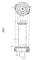
Fig. 1 is an outside view of a throttle grip apparatus according to a first embodiment of the invention. -
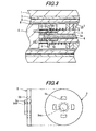
Fig. 2 is a section view taken along the II-II line shown inFig. 1 . -
Fig. 3 is an enlarged section view of such portion of the above throttle grip apparatus as exists near to an adjusting member. -
Fig. 4 is a side view and a front view of the adjusting member of the throttle grip apparatus. -
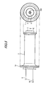
Fig. 5 is an outside view of a throttle grip apparatus according to a second embodiment of the invention. -
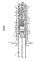
Fig. 6 is a section view taken along the VI-VI line shown inFig. 5 . - Exemplary embodiments of a throttle grip apparatus according to the invention are described with reference to accompanying drawings.
- A throttle grip apparatus according to a first embodiment of the invention is used to detect a rotation angle of a throttle grip mounted on a handle bar of a motorcycle and also to transmit a detected signal to an electronic control unit such as ECU mounted in the motorcycle. As shown in
Figs. 1 to 4 , the handle grip apparatus includes, as its main composing elements, athrottle grip 1, amagnet 6, anangle sensor 13 serving as a detector, a rotation sidefrictional plate 9 and a fixed sidefrictional plate 10 respectively disposed within a handle bar H, and an energizing member S1 and an adjusting mechanism (abolt member 4 and an adjusting member 5) cooperating together in constituting a resistance adjustor. - The
throttle grip 1 is mounted on a leading end portion of the handle bar H of the motorcycle and can be rotated relative to the handle bar H coaxially therewith. An outer peripheral surface of thethrottle grip 1 provides a grip portion which can be gripped by a driver, while thethrottle grip 1 includes a flange portion la on a base end side thereof. On an inner peripheral surface of thethrottle grip 1, there is provided a substantially cylindrical linkingcylindrical member 2, while the linkingcylindrical member 2 can be rotated together with thethrottle grip 1. - In an interior portion of the linking
cylindrical member 2, specifically, on a right end side thereof inFig. 2 , there are disposed a fixedmember 7 fixed to the handle bar H and a linkingmember 3 fixed to the linkingcylindrical member 2. The linkingmember 3 includes apenetration hole 3a formed in a central portion thereof in a longitudinal direction, while abolt member 4 is rotatably inserted into thepenetration hole 3a. Thebolt member 4 includes amale screw portion 4a having a male screw formed in an outer peripheral surface thereof and ahead portion 4b, while a tool fit-shape portion 4ba is formed in thehead portion 4b. - Further, a leading end face of the linking
cylindrical member 2 includes an opening 2a formed substantially in a center thereof, while the tool fit-shape portion 4ba is allowed to face an outside through the opening 2a. That is, thebolt member 4 includes the tool fit-shape portion 4ba facing the leading end side of thethrottle grip 1, whereby a tool can be fitted with the tool fit-shape portion 4ba and thebolt member 4 can be rotated using the tool. Here, in the present embodiment, the tool fit-shape portion 4ba is formed to have a hexagonal shape with which a hexagonal wrench can be fitted. - Into the leading end (in the drawings, the left end including multiple leg portions) of the linking
member 3, there is fitted themagnet 6, whereby themagnet 6 can be rotated together with the linkingmember 3. According to this structure, when thethrottle grip 1 is rotated, themagnet 6 is also rotated together with the linkingcylindrical member 2 and linkingmember 3, whereby a magnetic field generated in the portion that faces themagnet 6 is allowed to vary according to the rotation angle of themagnet 6. Here, themagnet 6 may be a permanent magnet or may be other type magnet (for example, a plastic magnet) which is capable of generating a magnetic field. - The angle sensor 13 (a detector) is used to detect variations in the magnetic field of the
magnet 6 in a non-contact manner and to detect the rotation angle of thethrottle grip 1 according to the value of the detected magnetic field variation; and, theangle sensor 13 is made of a chip-shaped member formed in abase plate 12. Here, thebase plate 12 includes not only theangle sensor 13 capable of increasing or decreasing an output voltage according to variations in the magnetic field caused by themagnet 6 but also an amplifier portion for amplifying the output signal of theangle sensor 13. Use ofsuch angle sensor 13 can facilitate the setting of a zero point (a signal of an initial position). Thebase plate 12 andangle sensor 13 are respectively stored within astorage member 11. Thestorage member 11 includes a storage space in the interior portion thereof and is fixed through a fixedcylindrical member 8 to the fixedmember 7. - From the
base plate 12, there is guided a cord h which extends within the handle bar H and is used to send an amplified detection signal to the outside. Here, inFig. 2 ,reference numeral 14 designates a binding band which is used to fix the cord h. Also, in a state where thebase plate 12 is stored in thestorage member 11, specific resin is filled into thestorage member 11, whereby thebase plate 12 can be molded with the resin. Thus, when themagnet 6 rotates with the rotation of thethrottle grip 1, the output signal of theangle sensor 13 is increased or decreased due to variations in the magnetic field that is generated from themagnet 6; and, therefore, the rotation angle of thethrottle grip 1 can be detected according to the output signal. The thus obtained detection signal is transmitted through the cord h to an ECU incorporated in a motorcycle, whereby the engine can be controlled according to the detection signal (that is, the engine can be controlled according to the rotation angle of the throttle grip 1). - On such side of the interior portion of the fixed
cylindrical member 8 as faces thefixed member 7, there is fixed the fixed sidefrictional plate 10 and also there is disposed the rotation sidefrictional plate 9 in such a manner that the surface thereof is in contact with the fixed sidefrictional plate 10. The rotation sidefrictional plate 9 can be rotated together with thethrottle grip 1 and also the surface thereof is pressed against the surface of the fixed sidefrictional plate 10 by an energizing member S1 made of a coil spring. Thus, when thethrottle grip 1 is rotated, the rotation sidefrictional plate 9 is rotated while it is pressed against the fixed sidefrictional plate 10, whereby there can be generated resistance and thus the rotation load of thethrottle grip 1 when thethrottle grip 1 is rotated. - Into a given portion of the linking
member 3, as shown inFig. 3 , there is inserted an adjustingmember 5, while the adjustingmember 5 is structured such that it is allowed to slide in the longitudinal direction (inFig. 3 , in the right and left direction) of the linkingmember 3. That is, in the adjustingmember 5, as shown inFig. 4 , there are formedmultiple holes 5b in a concentric circle manner; and, when the leg portions of the linkingmember 3 are inserted into theseholes 5b respectively, the adjustingmember 5 is allowed to slide in the axial direction of the linkingmember 3 and is prevented from moving in the peripheral direction. - Further, the adjusting
member 5 includes a burringportion 5a (rising portion) formed by burring the central portion of the adjustingmember 5 and, in the inner periphery of the burringportion 5a, there is formed a female screw 5aa which can be engaged with themale screw 4a of thebolt member 4. Thus, when thebolt member 4 is rotated around its axis, the adjustingmember 5 is allowed to move along themale screw 4a in the right and left direction inFig. 3 . Also, since one end of the energizing member S1 is contacted with one surface 5c of the adjustingmember 5 and the other end is contacted with the rotation sidefrictional plate 9, when the adjustingmember 5 moves right and left, the urging force (pressing force) of the energizing member S1 to be applied onto the rotation sidefrictional plate 9 can be adjusted. - For example, when a tool is fitted with the tool fit-shape portion 4ba and the
bolt member 4 is rotated in a given direction, the adjustingmember 5 is moved right inFig. 3 (in a direction to approach the rotation side frictional plate 9) to thereby be able to decrease the whole length of the energizing member S1 made of a coil spring, whereby the urging force (pressing force) of the energizing member S1 to be applied onto the rotation sidefrictional plate 9 can be increased. This can increase the resistance generated when thethrottle grip 1 is rotated and thus the rotation load of thethrottle grip 1 can be increased. - On the other hand, when a tool is fitted with the tool fit-shape portion 4ba and the
bolt member 4 is rotated in the opposite direction to the above-mentioned given direction, the adjustingmember 5 is moved left inFig. 3 (in a direction to move away from the rotation side frictional plate 9) to thereby be able to increase the whole length of the energizing member S1 made of a coil spring, whereby the urging force (pressing force) of the energizing member S1 to be applied onto the rotation sidefrictional plate 9 can be decreased. This can decrease the resistance generated when thethrottle grip 1 is rotated and thus the rotation load of thethrottle grip 1 an be decreased. - Also, one end of a spring S2 is contacted with the other surface 5d of the adjusting
member 5. The other end of the spring S2 is contacted with themagnet 6, whereby the spring S2 is capable of pressing themagnet 6 against thesurface 11a of thestorage member 11. Thanks to this structure, themagnet 6 is allowed to rotate together with thethrottle grip 1 while it is pressed against thesurface 11a of thestorage member 11, thereby being able to prevent the spacing dimension of themagnet 6 relative to theangle sensor 13 from being shifted due to the vibrations of the motorcycle, which can enhance the precision of the throttle grip apparatus further. Here, as described above, since, a tool is fitted with the tool fit-shape portion 4ba and thebolt member 4 is rotated using the tool, the adjustingmember 5 is moved right or left inFig. 3 , by decreasing or increasing the whole length of the coil spring S2, the pressing force of themagnet 6 on thesurface 11a can be adjusted. - According to the present embodiment, to such position of the handle bar H as adjoins the
throttle grip 1, there is fixed a case C; and, within the case C, there is stored an increaseddiameter portion 2b which is formed on the base end side of the linkingmember 2. Within the increaseddiameter portion 2b, there is disposed areturn spring 15. One end of thereturn spring 15 is fixed to the increaseddiameter portion 2b, while the other end is fixed to the case C side of the linkingmember 2. When the gripping force of the hand of the driver having rotated thethrottle grip 1 is loosened, thethrottle grip 1 can be rotated toward its initial position. - According to the present embodiment, since the frictional plates (rotation side
frictional plate 9 and fixed side frictional plate 10), when thethrottle grip 1 is rotated, capable of generating the resistance and thus the rotation load of thethrottle grip 1 are disposed within the handle bar H, even when the throttle wire is omitted, thethrottle grip 1 can be operated with no uncomfortable feeling and also the size of the throttle grip apparatus can be reduced. Also, since the cord h for transmitting the detection signal of theangle sensor 13 to the outside is disposed so as to extend within the handle bar H, the handling of the cord h can be facilitated, which can enhance the design of the appearance of the throttle grip apparatus. - Further, the frictional plates include the rotation side
frictional plate 9 which can be rotated together with thethrottle grip 1, and the fixed sidefrictional plate 10 which is fixed to the interior of the handle bar H and is contacted with the rotation sidefrictional plate 9. The resistance adjusting unit includes the energizing member S1 for pressing the rotation sidefrictional plate 9 against the fixed sidefrictional plate 10, and the adjusting mechanism (bolt member 4 and adjusting member 5) capable of arbitrarily changing the urging force of the energizing member S1 from outside through theopening 2a. According to the resistance adjusting unit, since, by operating the adjusting mechanism, the pressing force of the rotation sidefrictional plate 9 against the fixed sidefrictional plate 10 can be adjusted, the resistance generated by the frictional plates can be adjusted more easily. - Still further, according to the present embodiment, since there is provided the resistance adjusting unit (energizing member S1,
bolt member 4 and adjusting member 5) which is capable of arbitrarily adjusting the resistance to by the frictional plates (rotation sidefrictional plate 9 and fixed side frictional plate 10), the rotation load of thethrottle grip 1 can be arbitrarily changed according to the taste of a driver and, in spite of omission of the throttle wire, thethrottle grip 1 can be operated with no uncomfortable feeling. The adjusting mechanism includes the tool fit-shape portion 4ba facing the leading end of thethrottle grip 1 and is structured such that, by fitting a tool with the tool fit-shape portion 4ba and rotating the adjusting unit, the urging force of the energizing member S1 can be changed arbitrarily. Therefore, the resistance to be generated by the frictional plates (rotation sidefrictional plate 9 and fixed side frictional plate 10) can be adjusted still more easily. - Description will be given below of a second embodiment of a throttle grip apparatus according to the invention.
- A throttle grip apparatus according to the present embodiment, similarly to the first embodiment, is used to detect the rotation angle of a throttle grip mounted on a handle bar of a motorcycle and to transmit the thus detected signal to an electronic control unit such as ECU mounted in the motorcycle. As shown in
Figs. 5 and6 , the present handle grip apparatus includes, as its main composing elements, athrottle grip 1, amagnet 6, anangle sensor 13, a rotation sidefrictional plate 9 and a fixed sidefrictional plate 10 respectively disposed within a handle bar H, and an energizing member S1 and an adjusting mechanism (abolt member 4 and an adjusting member 5) cooperating together in constituting a resistance adjusting unit. Here, the composing elements of the present embodiment similar to those of the first embodiment are given the same designations and thus the detailed description thereof is omitted here. - Within the fixed
cylindrical member 8 according to the present embodiment, there is disposed a return spring 15' for energizing thethrottle grip 1 in the initial position direction and also aspring receiver 16 fixed to the linkingmember 3, while one end of the return spring 15' is secured to thespring receiver 16. Also, the other end of the return spring 15' is secured to the fixedmember 7. When the gripping force of the hand of a driver having rotated thethrottle grip 1 is loosed using the thus structured return spring 15', thethrottle grip 1 can be rotated toward its initial position. - According to the present embodiment, similarly to the first embodiment, since the frictional plates (rotation side
frictional plate 9 and fixed side frictional plate 10), when thethrottle grip 1 is rotated, capable of generating the resistance and thus the rotation load of thethrottle grip 1 are disposed within the handle bar H, even when the throttle wire is omitted, thethrottle grip 1 can be operated with no uncomfortable feeling; and also, since the return spring 15' is provided within the handle bar H, the size of the throttle grip apparatus can be reduced still further. - Although description has been given heretofore of the exemplary embodiments of the invention, the invention is not limited to them. For example, as a condition indispensable for the structure of the invention, the frictional plates (rotation side
frictional plate 9 and fixed side frictional plate 10) must be disposed within the handle bar H. Also, the resistance adjusting unit is not limited to the above-mentioned embodiments but other various units are also possible, provided that they can arbitrarily adjust the resistance to be generated by the frictional plates. - Further, instead of the
angle sensor 13, there may also be employed other types of detecting members, provided that they can detect variations in the magnetic field of themagnet 6 in a non-contact manner and can detect the rotation angle of thethrottle grip 1 according to the thus detected value.
Here, in the above embodiments, the throttle grip apparatus is mounted on the handle bar of the motorcycle but it may also be mounted on other types of vehicles including a handle bar (for example, an ATV and a snowmobile). - The present invention can apply to various types of throttle grip apparatus having different appearances or having other functions, provided they are structured such that the frictional plates, when the throttle grip is rotated, capable of generating resistance and thus the rotation load of the throttle grip are disposed within the handle bar.
-
- 1:
- Throttle grip
- 2:
- Linking cylindrical member
- 3:
- Linking member
- 4:
- Bolt member (adjusting mechanism)
- 4ba:
- Tool fit-shape portion
- 5:
- Adjusting member (adjusting mechanism)
- 6:
- Magnet
- 7:
- Fixed member
- 8:
- Fixed cylindrical member
- 9:
- Rotation side frictional plate
- 10:
- Fixed side frictional plate
- 11:
- Storage member
- 12:
- Base plate
- 13:
- Angle sensor (a detector)
- 14:
- Binding band
- 15, 15':
- Return spring
- 16:
- Spring receiver
- h:
- Cord
- H:
- Handle bar
- C:
- Case
- S1:
- Energizing member
- S2:
- Coil spring
Claims (3)
- A throttle grip apparatus comprising:a handle bar (H);a throttle grip (1) rotatably mounted on a leading end of said handle bar (H);a magnet (6) rotatable together with the throttle grip (1);a detector (13) configured to detect variations in a magnetic field of the magnet (6) in a non-contact manner to detect a rotation angle of the throttle grip (1) based on a detected value of the detector (13); anda frictional plate (9, 10) configured to generate a resistance to a rotation of the throttle grip (1) to generate a rotation load of the throttle grip (1),wherein the detected value of the detector (13) can be used as a basis for controlling an engine of the vehicle andwherein the frictional plate (9, 10) is disposed within the handle bar (H),characterized bya resistance adjustor (S1, 4, 5) configured to adjust the resistance generated by the frictional plate (9, 10).
- The throttle grip apparatus according to claim 1, wherein the frictional plate (9, 10) includes:a rotation side frictional plate (9) rotatable together with the throttle grip (1); anda fixed side frictional plate (10) which is fixed to an interior of the handle bar (H) and is in contact with the rotation side frictional plate (9), andwherein the resistance adjustor includes:an urging member (S1) configured to press the rotation side frictional plate (9) against the fixed side frictional plate (10); andan adjusting mechanism (4, 5) configured to change an urging force of the urging member (S1) from outside,wherein, by operating the adjusting mechanism (4, 5), a pressing force of the rotation side frictional plate (9) against the fixed side frictional plate (10) is adjusted.
- The throttle grip apparatus according to claim 2, wherein the adjusting mechanism (4, 5) includes a tool fit-shape portion (4ba) facing a leading end of the throttle grip (1), and the urging force of the urging member (S1) is changed by fitting a tool with the tool fit-shape portion (4ba) and rotating the adjusting mechanism (4).
Applications Claiming Priority (1)
| Application Number | Priority Date | Filing Date | Title |
|---|---|---|---|
| JP2008329638A JP5311556B2 (en) | 2008-12-25 | 2008-12-25 | Throttle grip device |
Publications (2)
| Publication Number | Publication Date |
|---|---|
| EP2202139A1 EP2202139A1 (en) | 2010-06-30 |
| EP2202139B1 true EP2202139B1 (en) | 2011-08-03 |
Family
ID=41622210
Family Applications (1)
| Application Number | Title | Priority Date | Filing Date |
|---|---|---|---|
| EP09179775A Not-in-force EP2202139B1 (en) | 2008-12-25 | 2009-12-18 | Throttle grip apparatus |
Country Status (7)
| Country | Link |
|---|---|
| US (1) | US8336423B2 (en) |
| EP (1) | EP2202139B1 (en) |
| JP (1) | JP5311556B2 (en) |
| CN (1) | CN101761400A (en) |
| AT (1) | ATE518739T1 (en) |
| BR (1) | BRPI0905193A2 (en) |
| TW (1) | TWI491530B (en) |
Families Citing this family (15)
| Publication number | Priority date | Publication date | Assignee | Title |
|---|---|---|---|---|
| DE102006060345A1 (en) * | 2006-12-20 | 2008-06-26 | Gustav Magenwirth Gmbh & Co. Kg | handle tube |
| JP5064342B2 (en) * | 2008-09-19 | 2012-10-31 | 本田技研工業株式会社 | Throttle opening detection device for saddle-ride type vehicles |
| JP5448148B2 (en) * | 2009-06-05 | 2014-03-19 | 朝日電装株式会社 | Throttle grip device |
| DE102010013686A1 (en) * | 2010-04-01 | 2011-10-06 | Gustav Magenwirth Gmbh & Co. Kg | Throttle grip |
| JP2012047624A (en) * | 2010-08-27 | 2012-03-08 | Nippon Seiki Co Ltd | Position detection device |
| JP5710949B2 (en) * | 2010-12-03 | 2015-04-30 | 朝日電装株式会社 | Throttle device |
| US8869649B2 (en) * | 2011-07-12 | 2014-10-28 | Shimano Inc. | Bicycle shift operating device |
| US8887594B2 (en) * | 2012-02-17 | 2014-11-18 | Aks Engineering, Llc | Assembly for selectively locking the angular position of a biased throttle grip |
| JP2013203176A (en) * | 2012-03-28 | 2013-10-07 | Nippon Seiki Co Ltd | Position detection device |
| JP2018001883A (en) * | 2016-06-28 | 2018-01-11 | 株式会社シマノ | Bar end for bicycle |
| CN106428382B (en) * | 2016-12-14 | 2022-06-03 | 上海东动科技有限公司 | Throttle is changeed handle and electric motor car |
| FR3063043B1 (en) | 2017-02-23 | 2019-03-15 | Continental Automotive France | CONTROL SYSTEM FOR A VEHICLE EQUIPPED WITH ELECTRICAL CONTROLS |
| JP6940573B2 (en) * | 2019-10-01 | 2021-09-29 | 本田技研工業株式会社 | Saddle-type vehicle and operating device |
| JP7431120B2 (en) * | 2020-07-16 | 2024-02-14 | 東洋電装株式会社 | accelerator position sensor |
| CN114559379B (en) * | 2022-03-23 | 2023-12-01 | 潍坊路加精工有限公司 | Throttle handle location frock switching device |
Family Cites Families (11)
| Publication number | Priority date | Publication date | Assignee | Title |
|---|---|---|---|---|
| DE69008298T2 (en) * | 1989-10-20 | 1994-08-04 | Campagnolo Srl | Twist grip device for actuating the gear shifts of a bicycle. |
| JP2902490B2 (en) | 1991-02-01 | 1999-06-07 | ヤマハ発動機株式会社 | Motorcycle motorcycle throttle opening sensor mounting structure |
| JP3078548B1 (en) * | 1999-11-08 | 2000-08-21 | 健二 鈴木 | Throttle opening retention unit for motorcycles |
| DE10027193B4 (en) * | 2000-05-31 | 2013-04-04 | Gustav Magenwirth Gmbh & Co. Kg | Throttle grip |
| JP4112876B2 (en) * | 2002-02-26 | 2008-07-02 | ヤマハ発動機株式会社 | Throttle opening detection device |
| US6978694B2 (en) * | 2002-12-06 | 2005-12-27 | Magneti Marelli Powertrain U.S.A., Inc. | Handlebar throttle controller with hysteresis |
| JP4255405B2 (en) * | 2004-04-23 | 2009-04-15 | 朝日電装株式会社 | Throttle grip device |
| US7287512B2 (en) * | 2006-01-10 | 2007-10-30 | Harley-Davidson Motor Company Group, Inc. | Throttle position sensor |
| ITTO20060526A1 (en) * | 2006-07-19 | 2008-01-20 | Bitron Spa | KNOB CONTROL DEVICE, PARTICULARLY FOR MOTOR VEHICLES. |
| JP4846705B2 (en) * | 2007-12-18 | 2011-12-28 | 本田技研工業株式会社 | Vehicle throttle device |
| JP5448148B2 (en) * | 2009-06-05 | 2014-03-19 | 朝日電装株式会社 | Throttle grip device |
-
2008
- 2008-12-25 JP JP2008329638A patent/JP5311556B2/en not_active Expired - Fee Related
-
2009
- 2009-12-17 TW TW098143335A patent/TWI491530B/en active
- 2009-12-18 EP EP09179775A patent/EP2202139B1/en not_active Not-in-force
- 2009-12-18 AT AT09179775T patent/ATE518739T1/en not_active IP Right Cessation
- 2009-12-22 BR BRPI0905193-7A patent/BRPI0905193A2/en not_active IP Right Cessation
- 2009-12-23 US US12/645,775 patent/US8336423B2/en active Active
- 2009-12-25 CN CN200910249571.8A patent/CN101761400A/en active Pending
Also Published As
| Publication number | Publication date |
|---|---|
| US20100162848A1 (en) | 2010-07-01 |
| JP5311556B2 (en) | 2013-10-09 |
| BRPI0905193A2 (en) | 2011-03-22 |
| CN101761400A (en) | 2010-06-30 |
| US8336423B2 (en) | 2012-12-25 |
| TW201033071A (en) | 2010-09-16 |
| JP2010149684A (en) | 2010-07-08 |
| EP2202139A1 (en) | 2010-06-30 |
| TWI491530B (en) | 2015-07-11 |
| ATE518739T1 (en) | 2011-08-15 |
Similar Documents
| Publication | Publication Date | Title |
|---|---|---|
| EP2202139B1 (en) | Throttle grip apparatus | |
| EP2263933B1 (en) | Throttle grip apparatus | |
| EP1767831B1 (en) | Shift control device for saddle-riding-type vehicle, and saddle-riding-type vehicle | |
| JP4063435B2 (en) | Car | |
| US8109123B2 (en) | Riveting unit for electric rivet gun | |
| US7412906B2 (en) | Steering system torque sensor | |
| JP2005075320A (en) | Pedal reaction force device | |
| US9428247B2 (en) | Control device | |
| JP5442323B2 (en) | Throttle grip device | |
| EP3498582B1 (en) | Throttle grip device | |
| JP2004339945A (en) | Throttle grip device | |
| WO2014132749A1 (en) | V-belt type stepless transmission | |
| JP6855892B2 (en) | Accelerator operating device | |
| JP5254345B2 (en) | Vehicle range switching device | |
| JP2019082151A (en) | Throttle grip device | |
| JP5180055B2 (en) | Throttle grip device | |
| JP2004239324A (en) | Pad clearance adjusting method for electric disk brake | |
| JPH07232647A (en) | Steering torque detecting device in power steering device | |
| JP2024058441A (en) | Throttle grip device | |
| JP2021021355A (en) | Throttle grip device | |
| JP2001175345A (en) | Pedal device for automobile and damper used for the pedal device | |
| JP2024058440A (en) | Throttle grip device | |
| EP1342638A3 (en) | Steering equipment for vehicles |
Legal Events
| Date | Code | Title | Description |
|---|---|---|---|
| PUAI | Public reference made under article 153(3) epc to a published international application that has entered the european phase |
Free format text: ORIGINAL CODE: 0009012 |
|
| AK | Designated contracting states |
Kind code of ref document: A1 Designated state(s): AT BE BG CH CY CZ DE DK EE ES FI FR GB GR HR HU IE IS IT LI LT LU LV MC MK MT NL NO PL PT RO SE SI SK SM TR |
|
| AX | Request for extension of the european patent |
Extension state: AL BA RS |
|
| 17P | Request for examination filed |
Effective date: 20101111 |
|
| GRAP | Despatch of communication of intention to grant a patent |
Free format text: ORIGINAL CODE: EPIDOSNIGR1 |
|
| GRAS | Grant fee paid |
Free format text: ORIGINAL CODE: EPIDOSNIGR3 |
|
| GRAA | (expected) grant |
Free format text: ORIGINAL CODE: 0009210 |
|
| AK | Designated contracting states |
Kind code of ref document: B1 Designated state(s): AT BE BG CH CY CZ DE DK EE ES FI FR GB GR HR HU IE IS IT LI LT LU LV MC MK MT NL NO PL PT RO SE SI SK SM TR |
|
| REG | Reference to a national code |
Ref country code: GB Ref legal event code: FG4D |
|
| REG | Reference to a national code |
Ref country code: CH Ref legal event code: EP |
|
| REG | Reference to a national code |
Ref country code: IE Ref legal event code: FG4D |
|
| REG | Reference to a national code |
Ref country code: DE Ref legal event code: R096 Ref document number: 602009001978 Country of ref document: DE Effective date: 20110929 |
|
| REG | Reference to a national code |
Ref country code: NL Ref legal event code: VDEP Effective date: 20110803 |
|
| LTIE | Lt: invalidation of european patent or patent extension |
Effective date: 20110803 |
|
| PG25 | Lapsed in a contracting state [announced via postgrant information from national office to epo] |
Ref country code: SE Free format text: LAPSE BECAUSE OF FAILURE TO SUBMIT A TRANSLATION OF THE DESCRIPTION OR TO PAY THE FEE WITHIN THE PRESCRIBED TIME-LIMIT Effective date: 20110803 Ref country code: FI Free format text: LAPSE BECAUSE OF FAILURE TO SUBMIT A TRANSLATION OF THE DESCRIPTION OR TO PAY THE FEE WITHIN THE PRESCRIBED TIME-LIMIT Effective date: 20110803 Ref country code: NL Free format text: LAPSE BECAUSE OF FAILURE TO SUBMIT A TRANSLATION OF THE DESCRIPTION OR TO PAY THE FEE WITHIN THE PRESCRIBED TIME-LIMIT Effective date: 20110803 Ref country code: LT Free format text: LAPSE BECAUSE OF FAILURE TO SUBMIT A TRANSLATION OF THE DESCRIPTION OR TO PAY THE FEE WITHIN THE PRESCRIBED TIME-LIMIT Effective date: 20110803 Ref country code: PT Free format text: LAPSE BECAUSE OF FAILURE TO SUBMIT A TRANSLATION OF THE DESCRIPTION OR TO PAY THE FEE WITHIN THE PRESCRIBED TIME-LIMIT Effective date: 20111205 Ref country code: NO Free format text: LAPSE BECAUSE OF FAILURE TO SUBMIT A TRANSLATION OF THE DESCRIPTION OR TO PAY THE FEE WITHIN THE PRESCRIBED TIME-LIMIT Effective date: 20111103 Ref country code: HR Free format text: LAPSE BECAUSE OF FAILURE TO SUBMIT A TRANSLATION OF THE DESCRIPTION OR TO PAY THE FEE WITHIN THE PRESCRIBED TIME-LIMIT Effective date: 20110803 Ref country code: IS Free format text: LAPSE BECAUSE OF FAILURE TO SUBMIT A TRANSLATION OF THE DESCRIPTION OR TO PAY THE FEE WITHIN THE PRESCRIBED TIME-LIMIT Effective date: 20111203 |
|
| REG | Reference to a national code |
Ref country code: AT Ref legal event code: MK05 Ref document number: 518739 Country of ref document: AT Kind code of ref document: T Effective date: 20110803 |
|
| PG25 | Lapsed in a contracting state [announced via postgrant information from national office to epo] |
Ref country code: AT Free format text: LAPSE BECAUSE OF FAILURE TO SUBMIT A TRANSLATION OF THE DESCRIPTION OR TO PAY THE FEE WITHIN THE PRESCRIBED TIME-LIMIT Effective date: 20110803 Ref country code: GR Free format text: LAPSE BECAUSE OF FAILURE TO SUBMIT A TRANSLATION OF THE DESCRIPTION OR TO PAY THE FEE WITHIN THE PRESCRIBED TIME-LIMIT Effective date: 20111104 Ref country code: PL Free format text: LAPSE BECAUSE OF FAILURE TO SUBMIT A TRANSLATION OF THE DESCRIPTION OR TO PAY THE FEE WITHIN THE PRESCRIBED TIME-LIMIT Effective date: 20110803 Ref country code: SI Free format text: LAPSE BECAUSE OF FAILURE TO SUBMIT A TRANSLATION OF THE DESCRIPTION OR TO PAY THE FEE WITHIN THE PRESCRIBED TIME-LIMIT Effective date: 20110803 Ref country code: CY Free format text: LAPSE BECAUSE OF FAILURE TO SUBMIT A TRANSLATION OF THE DESCRIPTION OR TO PAY THE FEE WITHIN THE PRESCRIBED TIME-LIMIT Effective date: 20110803 Ref country code: LV Free format text: LAPSE BECAUSE OF FAILURE TO SUBMIT A TRANSLATION OF THE DESCRIPTION OR TO PAY THE FEE WITHIN THE PRESCRIBED TIME-LIMIT Effective date: 20110803 |
|
| PG25 | Lapsed in a contracting state [announced via postgrant information from national office to epo] |
Ref country code: BE Free format text: LAPSE BECAUSE OF FAILURE TO SUBMIT A TRANSLATION OF THE DESCRIPTION OR TO PAY THE FEE WITHIN THE PRESCRIBED TIME-LIMIT Effective date: 20110803 |
|
| PG25 | Lapsed in a contracting state [announced via postgrant information from national office to epo] |
Ref country code: CZ Free format text: LAPSE BECAUSE OF FAILURE TO SUBMIT A TRANSLATION OF THE DESCRIPTION OR TO PAY THE FEE WITHIN THE PRESCRIBED TIME-LIMIT Effective date: 20110803 Ref country code: SK Free format text: LAPSE BECAUSE OF FAILURE TO SUBMIT A TRANSLATION OF THE DESCRIPTION OR TO PAY THE FEE WITHIN THE PRESCRIBED TIME-LIMIT Effective date: 20110803 |
|
| PG25 | Lapsed in a contracting state [announced via postgrant information from national office to epo] |
Ref country code: EE Free format text: LAPSE BECAUSE OF FAILURE TO SUBMIT A TRANSLATION OF THE DESCRIPTION OR TO PAY THE FEE WITHIN THE PRESCRIBED TIME-LIMIT Effective date: 20110803 Ref country code: RO Free format text: LAPSE BECAUSE OF FAILURE TO SUBMIT A TRANSLATION OF THE DESCRIPTION OR TO PAY THE FEE WITHIN THE PRESCRIBED TIME-LIMIT Effective date: 20110803 |
|
| PLBE | No opposition filed within time limit |
Free format text: ORIGINAL CODE: 0009261 |
|
| STAA | Information on the status of an ep patent application or granted ep patent |
Free format text: STATUS: NO OPPOSITION FILED WITHIN TIME LIMIT |
|
| PG25 | Lapsed in a contracting state [announced via postgrant information from national office to epo] |
Ref country code: DK Free format text: LAPSE BECAUSE OF FAILURE TO SUBMIT A TRANSLATION OF THE DESCRIPTION OR TO PAY THE FEE WITHIN THE PRESCRIBED TIME-LIMIT Effective date: 20110803 |
|
| 26N | No opposition filed |
Effective date: 20120504 |
|
| PG25 | Lapsed in a contracting state [announced via postgrant information from national office to epo] |
Ref country code: MC Free format text: LAPSE BECAUSE OF NON-PAYMENT OF DUE FEES Effective date: 20111231 |
|
| REG | Reference to a national code |
Ref country code: DE Ref legal event code: R097 Ref document number: 602009001978 Country of ref document: DE Effective date: 20120504 |
|
| REG | Reference to a national code |
Ref country code: IE Ref legal event code: MM4A |
|
| PG25 | Lapsed in a contracting state [announced via postgrant information from national office to epo] |
Ref country code: IE Free format text: LAPSE BECAUSE OF NON-PAYMENT OF DUE FEES Effective date: 20111218 |
|
| PG25 | Lapsed in a contracting state [announced via postgrant information from national office to epo] |
Ref country code: MT Free format text: LAPSE BECAUSE OF FAILURE TO SUBMIT A TRANSLATION OF THE DESCRIPTION OR TO PAY THE FEE WITHIN THE PRESCRIBED TIME-LIMIT Effective date: 20110803 Ref country code: MK Free format text: LAPSE BECAUSE OF FAILURE TO SUBMIT A TRANSLATION OF THE DESCRIPTION OR TO PAY THE FEE WITHIN THE PRESCRIBED TIME-LIMIT Effective date: 20110803 |
|
| PG25 | Lapsed in a contracting state [announced via postgrant information from national office to epo] |
Ref country code: SM Free format text: LAPSE BECAUSE OF FAILURE TO SUBMIT A TRANSLATION OF THE DESCRIPTION OR TO PAY THE FEE WITHIN THE PRESCRIBED TIME-LIMIT Effective date: 20110803 |
|
| PG25 | Lapsed in a contracting state [announced via postgrant information from national office to epo] |
Ref country code: LU Free format text: LAPSE BECAUSE OF NON-PAYMENT OF DUE FEES Effective date: 20111218 |
|
| PG25 | Lapsed in a contracting state [announced via postgrant information from national office to epo] |
Ref country code: BG Free format text: LAPSE BECAUSE OF FAILURE TO SUBMIT A TRANSLATION OF THE DESCRIPTION OR TO PAY THE FEE WITHIN THE PRESCRIBED TIME-LIMIT Effective date: 20111103 |
|
| PG25 | Lapsed in a contracting state [announced via postgrant information from national office to epo] |
Ref country code: TR Free format text: LAPSE BECAUSE OF FAILURE TO SUBMIT A TRANSLATION OF THE DESCRIPTION OR TO PAY THE FEE WITHIN THE PRESCRIBED TIME-LIMIT Effective date: 20110803 |
|
| PG25 | Lapsed in a contracting state [announced via postgrant information from national office to epo] |
Ref country code: ES Free format text: LAPSE BECAUSE OF FAILURE TO SUBMIT A TRANSLATION OF THE DESCRIPTION OR TO PAY THE FEE WITHIN THE PRESCRIBED TIME-LIMIT Effective date: 20111114 Ref country code: HU Free format text: LAPSE BECAUSE OF FAILURE TO SUBMIT A TRANSLATION OF THE DESCRIPTION OR TO PAY THE FEE WITHIN THE PRESCRIBED TIME-LIMIT Effective date: 20110803 |
|
| REG | Reference to a national code |
Ref country code: CH Ref legal event code: PL |
|
| PG25 | Lapsed in a contracting state [announced via postgrant information from national office to epo] |
Ref country code: LI Free format text: LAPSE BECAUSE OF NON-PAYMENT OF DUE FEES Effective date: 20131231 Ref country code: CH Free format text: LAPSE BECAUSE OF NON-PAYMENT OF DUE FEES Effective date: 20131231 |
|
| REG | Reference to a national code |
Ref country code: FR Ref legal event code: PLFP Year of fee payment: 7 |
|
| REG | Reference to a national code |
Ref country code: FR Ref legal event code: PLFP Year of fee payment: 8 |
|
| REG | Reference to a national code |
Ref country code: FR Ref legal event code: PLFP Year of fee payment: 9 |
|
| PGFP | Annual fee paid to national office [announced via postgrant information from national office to epo] |
Ref country code: GB Payment date: 20211028 Year of fee payment: 13 Ref country code: FR Payment date: 20211109 Year of fee payment: 13 Ref country code: DE Payment date: 20211102 Year of fee payment: 13 |
|
| PGFP | Annual fee paid to national office [announced via postgrant information from national office to epo] |
Ref country code: IT Payment date: 20211110 Year of fee payment: 13 |
|
| REG | Reference to a national code |
Ref country code: DE Ref legal event code: R119 Ref document number: 602009001978 Country of ref document: DE |
|
| GBPC | Gb: european patent ceased through non-payment of renewal fee |
Effective date: 20221218 |
|
| PG25 | Lapsed in a contracting state [announced via postgrant information from national office to epo] |
Ref country code: GB Free format text: LAPSE BECAUSE OF NON-PAYMENT OF DUE FEES Effective date: 20221218 Ref country code: DE Free format text: LAPSE BECAUSE OF NON-PAYMENT OF DUE FEES Effective date: 20230701 |
|
| PG25 | Lapsed in a contracting state [announced via postgrant information from national office to epo] |
Ref country code: FR Free format text: LAPSE BECAUSE OF NON-PAYMENT OF DUE FEES Effective date: 20221231 |
|
| PG25 | Lapsed in a contracting state [announced via postgrant information from national office to epo] |
Ref country code: IT Free format text: LAPSE BECAUSE OF NON-PAYMENT OF DUE FEES Effective date: 20221218 |