EP2201863A1 - Self-moving device for movable furniture parts - Google Patents
Self-moving device for movable furniture parts Download PDFInfo
- Publication number
- EP2201863A1 EP2201863A1 EP09165988A EP09165988A EP2201863A1 EP 2201863 A1 EP2201863 A1 EP 2201863A1 EP 09165988 A EP09165988 A EP 09165988A EP 09165988 A EP09165988 A EP 09165988A EP 2201863 A1 EP2201863 A1 EP 2201863A1
- Authority
- EP
- European Patent Office
- Prior art keywords
- longitudinal
- self
- slide base
- movable
- moving device
- Prior art date
- Legal status (The legal status is an assumption and is not a legal conclusion. Google has not performed a legal analysis and makes no representation as to the accuracy of the status listed.)
- Granted
Links
- 230000007246 mechanism Effects 0.000 claims abstract description 50
- 230000008878 coupling Effects 0.000 claims description 36
- 238000010168 coupling process Methods 0.000 claims description 36
- 238000005859 coupling reaction Methods 0.000 claims description 36
- 230000004044 response Effects 0.000 abstract description 2
- 230000004308 accommodation Effects 0.000 description 5
- 230000014509 gene expression Effects 0.000 description 2
- 238000009434 installation Methods 0.000 description 2
- 230000003139 buffering effect Effects 0.000 description 1
- 238000000034 method Methods 0.000 description 1
- 238000012986 modification Methods 0.000 description 1
- 230000004048 modification Effects 0.000 description 1
Images


Classifications
-
- A—HUMAN NECESSITIES
- A47—FURNITURE; DOMESTIC ARTICLES OR APPLIANCES; COFFEE MILLS; SPICE MILLS; SUCTION CLEANERS IN GENERAL
- A47B—TABLES; DESKS; OFFICE FURNITURE; CABINETS; DRAWERS; GENERAL DETAILS OF FURNITURE
- A47B88/00—Drawers for tables, cabinets or like furniture; Guides for drawers
- A47B88/40—Sliding drawers; Slides or guides therefor
- A47B88/453—Actuated drawers
- A47B88/46—Actuated drawers operated by mechanically-stored energy, e.g. by springs
- A47B88/47—Actuated drawers operated by mechanically-stored energy, e.g. by springs having both self-opening and self-closing mechanisms which interact with each other
Definitions
- the present invention relates to a self-moving device for movable furniture parts, in particular to a device that is self-closing and self-opening to control a movable part of a piece of furniture.
- the present invention relates to a self-moving device for movable furniture parts, which is applied to a movable part of a piece of furniture for providing self-closing and self-opening functions.
- a self-moving device for movable furniture parts comprising:
- the self-moving device for movable furniture parts further comprises an elastic piece disposed between the locking member and the slide base.
- the self-moving device for movable furniture parts further comprises a retaining mechanism, the retaining mechanism comprising a retaining member connected to the guiding member and a retaining spring connected between the retaining member and the guiding member, the retaining member being urged by the retaining spring to move longitudinally with respect to the movable part.
- the self-moving device for movable furniture parts further comprises an adjusting mechanism, the adjusting mechanism comprising a base fixed to the movable part and an adjusting member movably connected to the base, the adjusting member engaging with the retaining member.
- the guiding member comprises a board portion; a first supporting portion and a second supporting portion disposed at two ends of the board portion to be connected with the stationary part, the first longitudinal portion being disposed between the first supporting portion and the second supporting portion to be connected with the slide base; a second longitudinal portion and a fourth longitudinal portion disposed at two sides of the first longitudinal portion; and a third longitudinal portion disposed in the second longitudinal portion, the first longitudinal portion and the transverse portion being defined by an L-shaped groove, the second longitudinal portion being defined by a longitudinal slot, the third longitudinal portion being defined by a longitudinal groove, the fourth longitudinal portion being defined by a longitudinal wall, the stop portion being disposed at one side of the fourth longitudinal portion.
- the stop portion has a guiding surface to guide movement of the locking member.
- the slide base comprises a first portion, a second portion, a third portion, and a body connected to the first portion, the second portion, and the third portion, the first portion comprising a first sliding portion, a second sliding portion, and a third sliding portion which are connected to the first longitudinal portion, the second longitudinal portion, and the third longitudinal portion, respectively, the first sliding portion being a protuberance, the second sliding portion being a bulge, the third sliding portion being a protuberance.
- the slide base comprises a first portion, a second portion, a third portion, and a body connected to the first portion, the second portion, and the third portion, the first portion, the second portion and the body defining a channel, the third portion comprising a first wall, a second wall, and a coupling portion disposed between the first wall and the second wall, the coupling portion extending upwardly and obliquely from the third portion to form an inclined plane thereon, the first wall being adapted to engage with the first connecting portion, the coupling portion being adapted to engage with the second connecting portion.
- the self-moving device for movable furniture parts further comprises a coupling member having a spring room therein and a third elastic member disposed in the spring room, the coupling member urged by the third elastic member being movable, the coupling member having an inclined plane at an upper end thereof, the coupling member being adapted to engage with the second connecting portion.
- the self-moving device for movable furniture parts further comprises a buffer member, the buffer member comprising a buffer cylinder and a telescopic rod capable of moving with respect to the buffer cylinder, the telescopic rod extending outwards from the buffer cylinder to engage with the slide base.
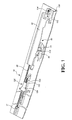
- a self-moving device for movable furniture parts of the present invention comprises a stationary part 16 which may a part of a cabinet or a stationary rail of a slide assembly.
- the present invention comprises a closing mechanism 40 mounted on the stationary part 16.
- the closing mechanism 40 comprises a guiding member 42 fixed on the stationary part 16, a slide base 44 movably connected to the guiding member 42, and a first elastic member 48 disposed on the stationary part 16.
- the first elastic member 48 is connected between the slide base 44 and the stationary part 16.
- the first elastic member 48 provides an elastic force to act on the slide base 44.
- a connecting seat 17 is fixed on the stationary part 16 and connected with the first elastic member 48 so as to keep the slide base 44 to move towards a first direction F1 constantly.
- a locking member 50 is connected to the slide base 44 and located between the slide base 44 and the guiding member 42.
- An opening mechanism 120 comprises a fixed portion 122 fixed on the stationary part 16, a push member 124 longitudinally movable in the fixed portion 122, and a second elastic member 126 disposed on the stationary part 16.
- the second elastic member 126 is connected between the fixed portion 122 and the push member 124 and provides an elastic force to the push member 124 to move towards a second direction F2 constantly.
- the second elastic member 126 has less elastic force than the first elastic member 48.
- a retaining mechanism 130 comprises a retaining member 132 longitudinally movable in the guiding member 42 and a retaining spring 134 connected between the guiding member 42 and the retaining member 132.
- the retaining member 132 is urged by the retaining spring 134 to move towards the second direction F2 constantly.
- Fig. 2 shows an exploded view of the closing mechanism 40 which comprises the guiding member 42.
- the slide base 44 is movably connected to the guiding member 42.
- the first elastic member 48 is connected to the slide base 44.
- the locking member 50 is connected to the slide base 44.
- An elastic piece 52 is provided between the slide base 44 and the locking member 50.
- the guiding member 42 comprises a board portion 54, a first supporting portion 56 and a second supporting portion 58 disposed at two ends of the board portion 54 to secure the board portion 54 to the stationary part 16.
- the first supporting portion 56 and the second supporting portion 58 define a space therebetween.
- a first longitudinal portion 60 is formed between the first supporting portion 56 and the second supporting portion 58.
- the first longitudinal portion 60 is integrally formed with the guiding member 42.
- a second longitudinal portion 62 and a fourth longitudinal portion 66 are formed at two sides of the first longitudinal portion 60, respectively.
- a third longitudinal portion 64 is formed in the second longitudinal portion 62.
- the first longitudinal portion 60 has a first end and a second end opposing to the first end.
- a transverse portion 68 extends from the first end of the first longitudinal portion 60.
- the first longitudinal portion 60 and the transverse portion 68 are defined by an L-shaped groove.
- the second longitudinal portion 62 is defined by a longitudinal slot.
- the third longitudinal portion 64 is defined by a longitudinal groove.
- the fourth longitudinal portion 66 is defined by a longitudinal wall.
- the slide base 44 comprises a first portion 84, a second portion 86, a third portion 88, and a body 90 connected to the first portion 84, the second portion 86, and the third portion 88.
- the first portion 84 comprises a first sliding portion 92, a second portion 94, and a third portion 96 which are connected to the first longitudinal portion 60, the second longitudinal portion 62 and the third longitudinal portion 64, respectively.
- the first sliding portion 92 is a protuberance which is slidably connected to the first longitudinal portion 60 and the transverse portion 68 of the guiding member 42.
- the second sliding portion 94 is a bulge which is slidably connected to the second longitudinal portion 62 of the guiding member 42.
- the third sliding portion 96 is a protuberance which is slidably connected to the third longitudinal portion 64 of the guiding member 42. Furthermore, a channel 98 is defined among the first portion 84, the second portion 86, and the body 90.
- the slide base 44 is straddled on the fourth longitudinal portion 66 of the guiding member 42 with the channel 98. According to the aforesaid configuration, the slide base 44 is linked to slide along the first longitudinal portion 60 and the transverse portion 68 of the guiding member 42 smoothly.
- the third portion 88 comprises a first wall 100, a second wall 102, and an elastic coupling portion 104 disposed between the first wall 100 and the second wall 102.
- the coupling portion 104 extends upwardly and obliquely from the third portion 88 to form an inclined plane 115.
- the coupling portion 104 of the slide base 44 further comprises a third elastic member 105 mounted on the slide base 44, a coupling member 107 movably disposed between the first wall 100 and the second wall 102 of the third portion 88 of the slide base 44.
- the coupling member 107 urged by the third elastic member 105 is movable, functioning as the coupling portion 104.
- the side base 44 has an accommodation room 45 and a pair of protruding portions 49 at inner sides of the accommodation room 45.
- the coupling member 107 comprises a pair of concave portions 113 corresponding to and engaging with the protruding portions 49 respectively, preventing the coupling member 107 in the accommodation room 45 from disengagement.
- the third elastic member 105 is located between the accommodation room 45 of the slide base 44 and the coupling member 107.
- the coupling member 107 is formed with a spring room 109, and a supporting post 47 is provided in the accommodation room 45 for the third elastic member 105 to be secured on the supporting post 47 and secured in the spring room 109 of the coupling member 107.
- the coupling member 107 has an inclined plane 111 on an upper end thereof.
- the locking member 50 is located between the guiding member 42 and the slide base 44.
- the locking member 50 has a first end 110 and a second end 112 opposing to the first end 110.
- the first end 110 of the locking member 50 is connected to the second portion 86 of the slide base 44, while the second end 112 of the locking member 50 is urged by the elastic piece 52 to act on the locking member 50.
- the second end 112 of the locking member 50 is forced to raise upwardly with respect to the slide base 44.
- the locking member 50 further has a first transverse portion 114 disposed between the first end 110 and the second end 112 and a second transverse portion 116.
- a locking space 118 is defined between the second transverse portion 116 and the first wall 100 of the slide base 44, referring to Fig. 1 .
- Fig. 4 shows the installation of the guiding member 42, the slide base 44 and the locking member 50.
- the guiding member 42 further comprises a stop portion 76 disposed at one side of the fourth longitudinal portion 66.
- the stop portion 76 has a guiding surface 78 corresponding to the first transverse portion 114 of the locking member 50, and is adapted to guide the first transverse portion 114 of the locking member 50 to slide along the guiding surface 78 and movable at an angle to the guiding surface 78.
- the sliding movement of the first transverse portion 114 presses the elastic piece 52 located between the locking member 50 and the slide base 44, referring to Fig. 2 . That is to say, the locking member 50 is movable against the stop portion 76.
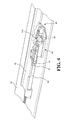
- Fig. 5 shows the configuration of the opening mechanism 120.
- the fixed portion 122 is fixed on the stationary part 16.
- the push member 124 is longitudinally movable in the fixed portion 122.
- the second elastic member 126 is mounted between the fixed portion 122 and the push member 124 in such a manner that the push member 124 is urged by the second elastic member 126 to move towards the second direction F2 constantly.
- Fig. 6 shows another preferred embodiment of the present invention.
- the second elastic member 126 is secured between the push member 124 and the guiding member 42, so that the push member 124 is urged by the second elastic member 126 to move towards the second direction F2.
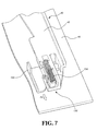
- the retaining member 132 of the retaining mechanism 130 is longitudinally movable in the guiding member 42 of the closing mechanism 40.
- the retaining spring 134 is disposed on the stationary part 16 and connected between the retaining member 132 and the guiding member 42.
- the elastic force of the retaining spring 134 acts on the retaining member 132 so that the retaining member 132 is urged to move towards the second direction F2 constantly.
- the retaining spring 134 will be compressed and the retaining member 132 will be longitudinally moved with respect to the guiding member 42.
- Fig. 8 shows another preferred embodiment of the retaining mechanism 130, which comprises a retaining seat 131 fixed on the stationary part 16, the retaining member 132 is longitudinally movable in the retaining seat 131, and the retaining spring 134 disposed between the retaining member 132 and the retaining seat 131.
- the retaining member 132 is urged by the retaining spring 134 to keep the retaining member 132 to move towards the second direction F2 constantly.
- the stationary part 16 is in the form of a stationary rail.
- the stationary part 16 has a first side wall 22, a second side wall 24, a bottom 26 extending between the first side wall 22 and the second side wall 24, and an upper wall 28 transversely extending from the second side wall 24.
- the first side wall 22 of the stationary part 16 is formed with a plurality of holes 30 such that the stationary part 16 is secured to a cabinet, a stationary frame or the like with fastening members, such as screws or bolts.
- the bottom 26 of the stationary part 16 is provided with a plurality of mounting portions 32 which may be in the form of protruding portions or concave holes for facilitating installation of the closing mechanism 40 and the opening mechanism 120.
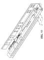
- Fig. 10 shows the configuration of a slide assembly 14.
- the slide assembly 14 comprises a first movable part 18 to slide longitudinally with respect to the stationary part 16, and a second movable part 20 disposed between the stationary part 16 and the first movable part 18.
- the first movable part 18 and the second movable part 20 are extendable with respect to the stationary part 16.
- the stationary part 16 is a stationary rail
- the first movable part 18 is a movable rail
- the second movable part 20 is an extension rail.
- the stationary part 16 may be mounted on a cabinet, a stationary frame or the like.
- the first movable part 18 may be mounted to a drawer, a movable frame or the like such that the drawer, the movable frame or the like may be pulled out from the cabinet, the stationary frame or the like by means of the movable part 18.
- the second movable part 20 is adapted to assist the first movable part 18 in extending for a long distance.
- the movable part 18 comprises a first connecting portion 34 and a second connecting portion 36.
- the slide base 44 corresponds to the first connecting portion 34 and the second connecting portion 36.
- the first connecting portion 34 and the second connecting portion 36 correspond to the closing mechanism 40 and the opening mechanism 120, respectively.
- the second transverse portion 116 of the locking member 50 and the first wall 100 of the third portion 88 of the closing mechanism 40 define the locking space 118 which is provided for the first connecting portion 34 of the movable part 18 to be positioned thereat.
- the push member 124 is engaged with the second connecting portion 36 of the movable part 18 and urged by the second elastic member 126 located between the fixed portion 122 and the push member 124 to push the second connecting portion 36 of the movable part 18 to move towards the second direction F2.
- the present invention further comprises an adjusting mechanism 140.
- the adjusting mechanism 140 comprises a base 142 fixedly connected to the movable part 18 and a movable adjusting member 144 which may be a threaded member to secure the base 142.
- the adjusting member 144 may be adjusted its distance with respect to the retaining member 132 of the retaining mechanism 130 for adjustment of the position between the movable part 18 and the stationary part 16.
- the closing mechanism 40 acts on the movable part 18 and the movable part 18 is retracted with respect to the stationary part 16.
- the first connecting portion 34 is located in the locking space 118 defined between the slide base 44 and the locking member 50.
- the locking member 50 will hold the first connecting portion 34, which links the movable part 18 to be pulled by the first elastic member 48 to move towards the first direction F1 to a closed position with respect to the stationary part 16.
- the second connecting portion 36 is pulled backwards and engaging with the push member 124 of the opening mechanism 120 which is also pulled backwards.
- the push member 124 Since the elastic force of the second elastic member 126 is less than that of the first elastic member 48, the push member 124 is pulled by the second connecting portion 36 to move backwards.
- the second elastic member 126 has an initiative force towards the second direction F2 which acts on the push member 124.
- the adjusting member 144 engages with the retaining member 132 at this moment to position the movable part 18 in place, thus the movable part 18 is moved towards the first direction F1 as the stationary part 16 does.
- the first transverse portion 114 of the locking member 50 is linked to move along the guiding surface 78 of the stop portion 76 of the guiding member 42, hence the locking member 50 is brought to a level drop to press the elastic piece 52 between the locking member 50 and the slide base 44, referring to Fig. 2 , which releases the engagement of the first connecting portion 34 of the movable portion 18 to form an open space in the locking space 118.
- the slide base 44 is pulled by the first elastic member 48 to move backwards and the moving force will be stopped when it encounters with the guiding member 42.
- the push member 124 of the opening mechanism 120 is pushed by the second connecting portion 36 of the movable part 18. The push member 124 will pull the second elastic member 126 during the movement.
- the pushing force from the second elastic member 126 to the push member 124 is larger than the initiative force. Therefore, when an external force in the first direction F1 is applied to the movable part 18, the first connecting portion 34 of the movable part 18 will be disengaged from the locking space 118. When the external force in the first direction F1 is released, the opening mechanism 120 will have the second elastic member 126 against the push member 124 towards the second direction F2, and the second connecting portion 36 of the movable part 18 will be pushed out by the push member 124.
- the movable part 18 is self-opening with respect to the stationary part 16, that is to say, the movable part 18 will be pushed outwards with respect to the stationary part 16. It means that the movable part 18 responds to the elastic force from the second elastic member 126 to generate a self-opening force with respect to the stationary part 16.
- Figs. 16a and 16b show the open status of the movable part 18 with respect to the stationary part 16.
- the second connecting portion 36 of the movable part 18 is pushed outwards by the push member 124 which is urged by the second elastic member 126 of the opening mechanism 120.
- the elastic force released from the second elastic member 126 will push the second connecting portion 36 to an open status with respect to the stationary part 16.
- the second connecting portion 36 is leaned against the coupling portion 104 and is stopped thereat, thus the movable part 18 remains in an open status with respect to the stationary part 16.
- the movable part 18 is already in an open status with respect to the stationary part 16.
- the first sliding portion 92 and the third sliding portion 96 of the slide base 44 will be pulled by the second connecting portion 36 of the movable part 18 to slide along the first longitudinal portion 60 and the third longitudinal portion 64 of the guiding member 42.
- the first sliding portion 92 and the third sliding portion 96 of the slide base 44 are pulled to move along the first longitudinal portion 60 and the third longitudinal portion 64 of the guiding member 42, upon the first sliding portion 92 reaches the end of the first longitudinal portion 60, it will slide into the transverse portion 68 which is interconnected with the first longitudinal portion 60, which causes the slide base 44 to deflect with respect to the guiding member 42 and to disengage from the second connecting portion 36 of the movable part 18 and the guiding member 42.
- the elastic force of the first elastic member 48 acts on the slide base 44 such that the slide base 44 is in an oblique and positioned status with respect to the guiding member 42 and the movable member 18 is free to be pulled outwards with respect to the stationary part 16.
- the first sliding portion 92 of the slide base 44 will stay in the transverse portion 68 of the guiding member 42. If the first sliding portion 92 of the slide base 44 is accidentally detached from the transverse portion 68 of the guiding member 42 and slides into the first longitudinal portion 60, as shown in Fig. 19 , the slide base 44 is pulled by the first elastic member 48 backwards, which causes the third sliding portion 96 of the slide base 44 to slide to the distal end of the third longitudinal portion 64 and stopped thereat in a disengaged status.
- the disengaged status is released.
- the movable part 18 is retracted into the stationary part 16.
- the second connecting portion 36 of the movable part 18 engages with inclined surface 115 of the coupling portion 104.
- the second connecting portion 36 will slide along the coupling portion 104 of the slide base 44 and a further pushing force will bring the second connecting portion 36 to slide over the coupling portion 104 of the slide base 44.
- the slide base 44 By pulling the movable portion 18 outwards with respect to the stationary part 16, the slide base 44 is linked to slide along the first longitudinal portion 60 of the guiding member 42 until the first sliding portion 92 of the slide base 44 reaches the transverse portion 68 and the slide base 44 is inclined to a positioned position, referring to Figs. 17 and 18 .
- the second connecting portion 36 of the movable part 18 engages with inclined plane 111 of the coupling member 107.
- the movement of the second connecting portion 36 will continue when the pushing force from the movable part 18, the second connecting portion 36 will slide along the coupling member 107 to press the third elastic member 105 and then slide over the coupling member 107.
- the third elastic member 105 applies its elastic force to the coupling member 107 so that the coupling member 107 returns its original position.
- the movable part 18 is pulled to move outwards with respect to the stationary part 16 to link the slide base 44 to slide.
- the movable part 18 is pushed backwards with respect to the stationary part 16.
- the slide base 44 will be linked to deflect until the first sliding portion 92 disengages from the transverse portion 68 of the guiding member 42 and returns to the first longitudinal portion 60 of the guiding member 42.
- the first connecting portion 34 is located in the locking space 118 defined between the second transverse portion 116 of the locking member 50 and the first wall 100 of the slide base 44.
- the slide base 44 is pulled backwards by the first elastic member 48 and the first connecting portion 34 of the movable part 18 is also pulled by the locking member 50 to move such that the movable part 18 is closed with respect to the stationary part 16.
- the present invention further comprises a buffer member 46.
- the buffer member 46 comprises a buffer cylinder 106 fixed on the stationary part 16 and a telescopic rod 108 which is able to extend linearly with respect to the buffer cylinder 106.
- the telescopic rod 108 is engaged with the third portion 88 of the slide base 44.
- the slide base 44 is moved at a rapid speed, the telescopic rod 108 will disengage from the third portion 88 and then be pushed outwards by the buffer cylinder 106 to engage with the third portion 88 once again for storing a buffer force ahead to act on the slide base 44.
- the present invention may be applied on a movable part of a piece of furniture to provide a self-closing and self-opening structure.
- the stationary part and the movable part may be a cabinet and a drawer, or a stationary rail and a movable rail.
Abstract
Description
- The present invention relates to a self-moving device for movable furniture parts, in particular to a device that is self-closing and self-opening to control a movable part of a piece of furniture.
- There are quite a few drawers having a self-opening function, which uses a restoring force to push a drawer in an open status when the drawer is released from its retaining situation. This device is designed only for opening the drawer, such as
U.S. Patent No.5,040,833 to Brunnert , titled "Closing Device for Drawers";U.S. Patent No.7,347,515 to Lu , titled "Sliding Rail Assembly Auto Opening Mechanism for Drawer";U.S. Patent No. 7,374,261 to Wang , titled "Push-Open Type Slide Structure";U.S. Patent No. 7,413,270 to Chang et al ., titled "Locking Device of Sliding Drawer; and European Patent No.EP 0743032 B1 titled "Drawer Slide". - Another device is designed only for closing the drawer, such as
U.S. Patent No. 7,537,296 to Leon et al ., titled "Dampened Movement Mechanism and Slide Incorporating the Same", which discloses an elastic force urging the drawer to a closed position and discloses a buffering technique. - However, all of the prior arts mentioned above, either self-closing or self-opening design is independent from each other. Therefore, it is necessary to install two devices for a drawer to be self-opening and self-closing, which increases the cost of assembly. In addition, it is not convenient for the end user to adjust the two different devices. So far, there is not a drawer or a slide assembly having both self-opening and self-closing functions.
- The present invention relates to a self-moving device for movable furniture parts, which is applied to a movable part of a piece of furniture for providing self-closing and self-opening functions.
- According to the present invention, there is provided a self-moving device for movable furniture parts, comprising:
- a stationary part;
- a movable part longitudinally slidable with respect to the stationary part and comprising a first connecting portion and a second connecting portion;
- a closing mechanism comprising a guiding member fixed on the stationary part, the guiding member comprising a first longitudinal portion and a transverse portion, the first longitudinal portion having a first end and a second end opposing to the first end, the transverse portion extending from the first end of the first longitudinal portion; a slide base connected to the first longitudinal portion; a first elastic member connected to the slide base; a locking member connected to the slide base, the slide base being urged by the first elastic member to move towards the second end of the first longitudinal member of the guiding member for the locking member to engage with the first connecting portion of the movable part; and a stop portion corresponding to the locking member for the locking member to lean on the stop portion to move, and
- an opening mechanism comprising a second elastic member disposed on the stationary part and a push member urged by the second elastic member to move;
- wherein when the movable part is retracted to a predetermined position with respect to the stationary part, the first connecting portion of the movable part engages with the locking member and the first connecting portion urged by the first elastic member forces the movable part to be self-closing towards the stationary part;
- wherein the locking member is movable in response to an external force to lean on the stop portion such that the first connecting portion of the movable part disengages from the locking member, and the movable part is urged by the second elastic member and pushed by the push member to be self-opening.
- Preferably, the self-moving device for movable furniture parts further comprises an elastic piece disposed between the locking member and the slide base.
- Preferably, the self-moving device for movable furniture parts further comprises a retaining mechanism, the retaining mechanism comprising a retaining member connected to the guiding member and a retaining spring connected between the retaining member and the guiding member, the retaining member being urged by the retaining spring to move longitudinally with respect to the movable part.
- Preferably, the self-moving device for movable furniture parts further comprises an adjusting mechanism, the adjusting mechanism comprising a base fixed to the movable part and an adjusting member movably connected to the base, the adjusting member engaging with the retaining member.
- Preferably, the guiding member comprises a board portion; a first supporting portion and a second supporting portion disposed at two ends of the board portion to be connected with the stationary part, the first longitudinal portion being disposed between the first supporting portion and the second supporting portion to be connected with the slide base; a second longitudinal portion and a fourth longitudinal portion disposed at two sides of the first longitudinal portion; and a third longitudinal portion disposed in the second longitudinal portion, the first longitudinal portion and the transverse portion being defined by an L-shaped groove, the second longitudinal portion being defined by a longitudinal slot, the third longitudinal portion being defined by a longitudinal groove, the fourth longitudinal portion being defined by a longitudinal wall, the stop portion being disposed at one side of the fourth longitudinal portion.
- Preferably, the stop portion has a guiding surface to guide movement of the locking member.
- Preferably, the slide base comprises a first portion, a second portion, a third portion, and a body connected to the first portion, the second portion, and the third portion, the first portion comprising a first sliding portion, a second sliding portion, and a third sliding portion which are connected to the first longitudinal portion, the second longitudinal portion, and the third longitudinal portion, respectively, the first sliding portion being a protuberance, the second sliding portion being a bulge, the third sliding portion being a protuberance.
- Alternatively, the slide base comprises a first portion, a second portion, a third portion, and a body connected to the first portion, the second portion, and the third portion, the first portion, the second portion and the body defining a channel, the third portion comprising a first wall, a second wall, and a coupling portion disposed between the first wall and the second wall, the coupling portion extending upwardly and obliquely from the third portion to form an inclined plane thereon, the first wall being adapted to engage with the first connecting portion, the coupling portion being adapted to engage with the second connecting portion.
- Preferably, the self-moving device for movable furniture parts further comprises a coupling member having a spring room therein and a third elastic member disposed in the spring room, the coupling member urged by the third elastic member being movable, the coupling member having an inclined plane at an upper end thereof, the coupling member being adapted to engage with the second connecting portion.
- Preferably, the self-moving device for movable furniture parts further comprises a buffer member, the buffer member comprising a buffer cylinder and a telescopic rod capable of moving with respect to the buffer cylinder, the telescopic rod extending outwards from the buffer cylinder to engage with the slide base.
- It is the primary object of the present invention to provide a self-moving device for movable furniture parts, which has an integrity and common of the parts and is cost-effective for assembly.
- It is another object of the present invention to provide a self-moving device for movable furniture parts, which is not necessary for the user to adjust a closing device and an open device, separately.
-
-
Fig. 1 is a perspective view showing a self-moving device mounted on a stationary part according to a first preferred embodiment of the present invention; -
Fig. 2 is an exploded view showing a closing mechanism according to the first preferred embodiment of the present invention; -
Fig. 3 is an exploded view showing a retaining mechanism and an adjusting mechanism according to a second preferred embodiment of the present invention; -
Fig. 4 is an assembled perspective view of the closing mechanism according to the first preferred embodiment of the present invention; -
Fig. 5 is a cross-sectional view showing an opening mechanism according to the first preferred embodiment of the present invention; -
Fig. 6 is a perspective view showing engagement of a slide base according to the second preferred embodiment of the present invention; -
Fig. 7 is a perspective view showing the retaining mechanism according to the first preferred embodiment of the present invention; -
Fig. 8 is a perspective view showing the retaining mechanism according to the second preferred embodiment of the present invention; -
Fig. 9 is a perspective view showing the self-moving device mounted on a stationary rail according to the first preferred embodiment of the present invention; -
Fig. 10 is perspective view showing the self-moving device mounted on a slide assembly according to the first preferred embodiment of the present invention; -
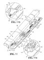
Fig. 11 is a perspective view showing the configuration of the self-moving device and the slide assembly according to the first preferred embodiment of the present invention; -
Fig. 11 a is an enlarged view of a portion of theFig. 11 ; -
Fig. 11b is an enlarged view of an another portion of theFig. 11 ; -
Fig. 12 is a partially sectioned perspective view showing the adjusting mechanism according to the first preferred embodiment of the present invention; -
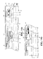
Fig. 13a is a schematic view showing a movable part in a retracted status according to the first preferred embodiment of the present invention; -
Fig. 13b is another schematic view showing the movable part in a retracted status according to the first preferred embodiment of the present invention; -
Fig. 14a is a schematic view showing the movable part pushed by an external force according to the first preferred embodiment of the present invention; -
Fig. 14b is another schematic view showing the movable part pushed by the external force according to the first preferred embodiment of the present invention; -
Fig. 15 is a perspective view showing a locking member guided by a guiding member to deflect when the movable part is pushed by the external force according to the first preferred embodiment of the present invention; -
Fig. 16a is a schematic view showing the movable part forced in a self-opening status according to the first preferred embodiment of the present invention; -
Fig. 16b is another schematic view showing the movable part forced in an open status according to the first preferred embodiment of the present invention; -
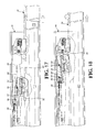
Fig. 17 is a schematic view showing the slide base linked by the movable part to move according to the first preferred embodiment of the present invention; -
Fig. 18 is a schematic view showing the slide base linked by the movable part to deflect according to the first preferred embodiment of the present invention; -
Fig. 19 is a schematic view showing the slide base malfunctioning and being pulled back according to the first preferred embodiment of the present invention; -
Fig. 20 is a schematic view showing the second connecting portion being engaged with the slide base again according to the first preferred embodiment of the present invention; -
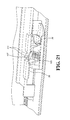
Fig. 21 is a schematic view showing the second connecting portion being engaged with a coupling member again according to the second preferred embodiment of the present invention; -
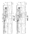
Fig. 22 is a schematic view showing the second connecting portion being engaged with the slide base according to the first preferred embodiment of the present invention; -
Fig. 23 is a schematic view showing the second connecting portion being pulled back according to the first preferred embodiment of the present invention; and -
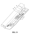
Fig. 24 is a perspective view showing a buffer member according to the first preferred embodiment of the present invention. - A self-moving device for movable furniture parts of the present invention, as shown in
Fig. 1 , comprises astationary part 16 which may a part of a cabinet or a stationary rail of a slide assembly. In this embodiment, the present invention comprises aclosing mechanism 40 mounted on thestationary part 16. Theclosing mechanism 40 comprises a guidingmember 42 fixed on thestationary part 16, aslide base 44 movably connected to the guidingmember 42, and a firstelastic member 48 disposed on thestationary part 16. The firstelastic member 48 is connected between theslide base 44 and thestationary part 16. The firstelastic member 48 provides an elastic force to act on theslide base 44. In a preferred embodiment, a connectingseat 17 is fixed on thestationary part 16 and connected with the firstelastic member 48 so as to keep theslide base 44 to move towards a first direction F1 constantly. A lockingmember 50 is connected to theslide base 44 and located between theslide base 44 and the guidingmember 42. Anopening mechanism 120 comprises a fixedportion 122 fixed on thestationary part 16, apush member 124 longitudinally movable in the fixedportion 122, and a secondelastic member 126 disposed on thestationary part 16. The secondelastic member 126 is connected between the fixedportion 122 and thepush member 124 and provides an elastic force to thepush member 124 to move towards a second direction F2 constantly. The secondelastic member 126 has less elastic force than the firstelastic member 48. Aretaining mechanism 130 comprises a retainingmember 132 longitudinally movable in the guidingmember 42 and a retainingspring 134 connected between the guidingmember 42 and the retainingmember 132. The retainingmember 132 is urged by the retainingspring 134 to move towards the second direction F2 constantly. -
Fig. 2 shows an exploded view of theclosing mechanism 40 which comprises the guidingmember 42. Theslide base 44 is movably connected to the guidingmember 42. The firstelastic member 48 is connected to theslide base 44. The lockingmember 50 is connected to theslide base 44. Anelastic piece 52 is provided between theslide base 44 and the lockingmember 50. - The guiding
member 42 comprises aboard portion 54, a first supportingportion 56 and a second supportingportion 58 disposed at two ends of theboard portion 54 to secure theboard portion 54 to thestationary part 16. The first supportingportion 56 and the second supportingportion 58 define a space therebetween. A firstlongitudinal portion 60 is formed between the first supportingportion 56 and the second supportingportion 58. Preferably, the firstlongitudinal portion 60 is integrally formed with the guidingmember 42. A secondlongitudinal portion 62 and a fourthlongitudinal portion 66 are formed at two sides of the firstlongitudinal portion 60, respectively. A thirdlongitudinal portion 64 is formed in the secondlongitudinal portion 62. In this embodiment, the firstlongitudinal portion 60 has a first end and a second end opposing to the first end. Atransverse portion 68 extends from the first end of the firstlongitudinal portion 60. In a preferred embodiment, the firstlongitudinal portion 60 and thetransverse portion 68 are defined by an L-shaped groove. The secondlongitudinal portion 62 is defined by a longitudinal slot. The thirdlongitudinal portion 64 is defined by a longitudinal groove. The fourthlongitudinal portion 66 is defined by a longitudinal wall. - The
slide base 44 comprises afirst portion 84, asecond portion 86, athird portion 88, and abody 90 connected to thefirst portion 84, thesecond portion 86, and thethird portion 88. Thefirst portion 84 comprises a first slidingportion 92, asecond portion 94, and athird portion 96 which are connected to the firstlongitudinal portion 60, the secondlongitudinal portion 62 and the thirdlongitudinal portion 64, respectively. Preferably, the first slidingportion 92 is a protuberance which is slidably connected to the firstlongitudinal portion 60 and thetransverse portion 68 of the guidingmember 42. The second slidingportion 94 is a bulge which is slidably connected to the secondlongitudinal portion 62 of the guidingmember 42. The third slidingportion 96 is a protuberance which is slidably connected to the thirdlongitudinal portion 64 of the guidingmember 42. Furthermore, achannel 98 is defined among thefirst portion 84, thesecond portion 86, and thebody 90. Theslide base 44 is straddled on the fourthlongitudinal portion 66 of the guidingmember 42 with thechannel 98. According to the aforesaid configuration, theslide base 44 is linked to slide along the firstlongitudinal portion 60 and thetransverse portion 68 of the guidingmember 42 smoothly. Thethird portion 88 comprises afirst wall 100, asecond wall 102, and anelastic coupling portion 104 disposed between thefirst wall 100 and thesecond wall 102. Thecoupling portion 104 extends upwardly and obliquely from thethird portion 88 to form aninclined plane 115. - As shown in
Fig. 3 , another preferred embodiment of thecoupling portion 104 of theslide base 44 further comprises a thirdelastic member 105 mounted on theslide base 44, acoupling member 107 movably disposed between thefirst wall 100 and thesecond wall 102 of thethird portion 88 of theslide base 44. Thecoupling member 107 urged by the thirdelastic member 105 is movable, functioning as thecoupling portion 104. In a preferred embodiment, theside base 44 has anaccommodation room 45 and a pair of protrudingportions 49 at inner sides of theaccommodation room 45. Thecoupling member 107 comprises a pair ofconcave portions 113 corresponding to and engaging with the protrudingportions 49 respectively, preventing thecoupling member 107 in theaccommodation room 45 from disengagement. The thirdelastic member 105 is located between theaccommodation room 45 of theslide base 44 and thecoupling member 107. Preferably, thecoupling member 107 is formed with aspring room 109, and a supportingpost 47 is provided in theaccommodation room 45 for the thirdelastic member 105 to be secured on the supportingpost 47 and secured in thespring room 109 of thecoupling member 107. Thecoupling member 107 has aninclined plane 111 on an upper end thereof. - The locking
member 50 is located between the guidingmember 42 and theslide base 44. In this embodiment, the lockingmember 50 has afirst end 110 and a second end 112 opposing to thefirst end 110. Thefirst end 110 of the lockingmember 50 is connected to thesecond portion 86 of theslide base 44, while the second end 112 of the lockingmember 50 is urged by theelastic piece 52 to act on the lockingmember 50. The second end 112 of the lockingmember 50 is forced to raise upwardly with respect to theslide base 44. The lockingmember 50 further has a firsttransverse portion 114 disposed between thefirst end 110 and the second end 112 and a secondtransverse portion 116. A lockingspace 118 is defined between the secondtransverse portion 116 and thefirst wall 100 of theslide base 44, referring toFig. 1 . -
Fig. 4 shows the installation of the guidingmember 42, theslide base 44 and the lockingmember 50. The guidingmember 42 further comprises astop portion 76 disposed at one side of the fourthlongitudinal portion 66. Thestop portion 76 has a guidingsurface 78 corresponding to the firsttransverse portion 114 of the lockingmember 50, and is adapted to guide the firsttransverse portion 114 of the lockingmember 50 to slide along the guidingsurface 78 and movable at an angle to the guidingsurface 78. The sliding movement of the firsttransverse portion 114 presses theelastic piece 52 located between the lockingmember 50 and theslide base 44, referring toFig. 2 . That is to say, the lockingmember 50 is movable against thestop portion 76. -
Fig. 5 shows the configuration of theopening mechanism 120. The fixedportion 122 is fixed on thestationary part 16. Thepush member 124 is longitudinally movable in the fixedportion 122. The secondelastic member 126 is mounted between the fixedportion 122 and thepush member 124 in such a manner that thepush member 124 is urged by the secondelastic member 126 to move towards the second direction F2 constantly.Fig. 6 shows another preferred embodiment of the present invention. The secondelastic member 126 is secured between thepush member 124 and the guidingmember 42, so that thepush member 124 is urged by the secondelastic member 126 to move towards the second direction F2. - As shown in
Fig. 7 , the retainingmember 132 of theretaining mechanism 130 is longitudinally movable in the guidingmember 42 of theclosing mechanism 40. The retainingspring 134 is disposed on thestationary part 16 and connected between the retainingmember 132 and the guidingmember 42. The elastic force of the retainingspring 134 acts on the retainingmember 132 so that the retainingmember 132 is urged to move towards the second direction F2 constantly. When the retainingmember 132 is urged by an external force towards a direction opposite to the second direction F2, the retainingspring 134 will be compressed and the retainingmember 132 will be longitudinally moved with respect to the guidingmember 42. -
Fig. 8 shows another preferred embodiment of theretaining mechanism 130, which comprises a retainingseat 131 fixed on thestationary part 16, the retainingmember 132 is longitudinally movable in the retainingseat 131, and the retainingspring 134 disposed between the retainingmember 132 and the retainingseat 131. The retainingmember 132 is urged by the retainingspring 134 to keep the retainingmember 132 to move towards the second direction F2 constantly. - As shown in
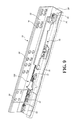
Fig. 9 , thestationary part 16 is in the form of a stationary rail. Thestationary part 16 has afirst side wall 22, asecond side wall 24, a bottom 26 extending between thefirst side wall 22 and thesecond side wall 24, and anupper wall 28 transversely extending from thesecond side wall 24. Preferably, thefirst side wall 22 of thestationary part 16 is formed with a plurality ofholes 30 such that thestationary part 16 is secured to a cabinet, a stationary frame or the like with fastening members, such as screws or bolts. The bottom 26 of thestationary part 16 is provided with a plurality of mountingportions 32 which may be in the form of protruding portions or concave holes for facilitating installation of theclosing mechanism 40 and theopening mechanism 120. -
Fig. 10 shows the configuration of aslide assembly 14. Theslide assembly 14 comprises a firstmovable part 18 to slide longitudinally with respect to thestationary part 16, and a secondmovable part 20 disposed between thestationary part 16 and the firstmovable part 18. The firstmovable part 18 and the secondmovable part 20 are extendable with respect to thestationary part 16. In this embodiment, thestationary part 16 is a stationary rail, the firstmovable part 18 is a movable rail, and the secondmovable part 20 is an extension rail. Thestationary part 16 may be mounted on a cabinet, a stationary frame or the like. The firstmovable part 18 may be mounted to a drawer, a movable frame or the like such that the drawer, the movable frame or the like may be pulled out from the cabinet, the stationary frame or the like by means of themovable part 18. The secondmovable part 20 is adapted to assist the firstmovable part 18 in extending for a long distance. - As shown in
Figs. 11, 11 a and 11 b, themovable part 18 comprises a first connectingportion 34 and a second connectingportion 36. Theslide base 44 corresponds to the first connectingportion 34 and the second connectingportion 36. When themovable part 18 is retracted with respect to thestationary part 16, the first connectingportion 34 and the second connectingportion 36 correspond to theclosing mechanism 40 and theopening mechanism 120, respectively. The secondtransverse portion 116 of the lockingmember 50 and thefirst wall 100 of thethird portion 88 of theclosing mechanism 40 define the lockingspace 118 which is provided for the first connectingportion 34 of themovable part 18 to be positioned thereat. Thepush member 124 is engaged with the second connectingportion 36 of themovable part 18 and urged by the secondelastic member 126 located between the fixedportion 122 and thepush member 124 to push the second connectingportion 36 of themovable part 18 to move towards the second direction F2. - As shown in
Fig. 12 , the present invention further comprises anadjusting mechanism 140. Theadjusting mechanism 140 comprises a base 142 fixedly connected to themovable part 18 and amovable adjusting member 144 which may be a threaded member to secure thebase 142. The adjustingmember 144 may be adjusted its distance with respect to the retainingmember 132 of theretaining mechanism 130 for adjustment of the position between themovable part 18 and thestationary part 16. - As shown in
Figs. 13a and 13b , theclosing mechanism 40 acts on themovable part 18 and themovable part 18 is retracted with respect to thestationary part 16. The first connectingportion 34 is located in the lockingspace 118 defined between theslide base 44 and the lockingmember 50. When the lockingmember 50 is pulled backwards by theslide base 44 with the firstelastic member 48, the lockingmember 50 will hold the first connectingportion 34, which links themovable part 18 to be pulled by the firstelastic member 48 to move towards the first direction F1 to a closed position with respect to thestationary part 16. The second connectingportion 36 is pulled backwards and engaging with thepush member 124 of theopening mechanism 120 which is also pulled backwards. Since the elastic force of the secondelastic member 126 is less than that of the firstelastic member 48, thepush member 124 is pulled by the second connectingportion 36 to move backwards. The secondelastic member 126 has an initiative force towards the second direction F2 which acts on thepush member 124. The adjustingmember 144 engages with the retainingmember 132 at this moment to position themovable part 18 in place, thus themovable part 18 is moved towards the first direction F1 as thestationary part 16 does. - As shown in
Figs. 14a, 14b , and15 , when themovable part 18 is pushed to move towards the first direction F1 and the adjustingmember 144 of theadjusting mechanism 140 pushes the retainingmember 132 of theretaining mechanism 130, the retainingmember 132 will press the retainingspring 134 to move longitudinally with respect to the guidingmember 42. Meantime, the first connectingportion 34 of themovable part 18 pushes thefirst wall 100 of theslide base 44 to move backwards, which links the lockingmember 50 to move backwards along with theslide base 44. The firsttransverse portion 114 of the lockingmember 50 is linked to move along the guidingsurface 78 of thestop portion 76 of the guidingmember 42, hence the lockingmember 50 is brought to a level drop to press theelastic piece 52 between the lockingmember 50 and theslide base 44, referring toFig. 2 , which releases the engagement of the first connectingportion 34 of themovable portion 18 to form an open space in the lockingspace 118. Theslide base 44 is pulled by the firstelastic member 48 to move backwards and the moving force will be stopped when it encounters with the guidingmember 42. Meanwhile, thepush member 124 of theopening mechanism 120 is pushed by the second connectingportion 36 of themovable part 18. Thepush member 124 will pull the secondelastic member 126 during the movement. The pushing force from the secondelastic member 126 to thepush member 124 is larger than the initiative force. Therefore, when an external force in the first direction F1 is applied to themovable part 18, the first connectingportion 34 of themovable part 18 will be disengaged from the lockingspace 118. When the external force in the first direction F1 is released, theopening mechanism 120 will have the secondelastic member 126 against thepush member 124 towards the second direction F2, and the second connectingportion 36 of themovable part 18 will be pushed out by thepush member 124. Thus themovable part 18 is self-opening with respect to thestationary part 16, that is to say, themovable part 18 will be pushed outwards with respect to thestationary part 16. It means that themovable part 18 responds to the elastic force from the secondelastic member 126 to generate a self-opening force with respect to thestationary part 16. -
Figs. 16a and 16b show the open status of themovable part 18 with respect to thestationary part 16. The second connectingportion 36 of themovable part 18 is pushed outwards by thepush member 124 which is urged by the secondelastic member 126 of theopening mechanism 120. The elastic force released from the secondelastic member 126 will push the second connectingportion 36 to an open status with respect to thestationary part 16. Preferably, the second connectingportion 36 is leaned against thecoupling portion 104 and is stopped thereat, thus themovable part 18 remains in an open status with respect to thestationary part 16. - As shown in
Fig. 17 , themovable part 18 is already in an open status with respect to thestationary part 16. When themovable part 18 is pulled further away from thestationary part 16, the first slidingportion 92 and the third slidingportion 96 of theslide base 44 will be pulled by the second connectingportion 36 of themovable part 18 to slide along the firstlongitudinal portion 60 and the thirdlongitudinal portion 64 of the guidingmember 42. - As shown in
Fig. 18 , the first slidingportion 92 and the third slidingportion 96 of theslide base 44 are pulled to move along the firstlongitudinal portion 60 and the thirdlongitudinal portion 64 of the guidingmember 42, upon the first slidingportion 92 reaches the end of the firstlongitudinal portion 60, it will slide into thetransverse portion 68 which is interconnected with the firstlongitudinal portion 60, which causes theslide base 44 to deflect with respect to the guidingmember 42 and to disengage from the second connectingportion 36 of themovable part 18 and the guidingmember 42. The elastic force of the firstelastic member 48 acts on theslide base 44 such that theslide base 44 is in an oblique and positioned status with respect to the guidingmember 42 and themovable member 18 is free to be pulled outwards with respect to thestationary part 16. - After the
movable part 18 is kept in an open status with respect to thestationary part 16, the first slidingportion 92 of theslide base 44 will stay in thetransverse portion 68 of the guidingmember 42. If the first slidingportion 92 of theslide base 44 is accidentally detached from thetransverse portion 68 of the guidingmember 42 and slides into the firstlongitudinal portion 60, as shown inFig. 19 , theslide base 44 is pulled by the firstelastic member 48 backwards, which causes the third slidingportion 96 of theslide base 44 to slide to the distal end of the thirdlongitudinal portion 64 and stopped thereat in a disengaged status. - As shown in
Fig. 20 , the disengaged status is released. Themovable part 18 is retracted into thestationary part 16. The second connectingportion 36 of themovable part 18 engages withinclined surface 115 of thecoupling portion 104. By pushing themovable part 18 inwards, the second connectingportion 36 will slide along thecoupling portion 104 of theslide base 44 and a further pushing force will bring the second connectingportion 36 to slide over thecoupling portion 104 of theslide base 44. By pulling themovable portion 18 outwards with respect to thestationary part 16, theslide base 44 is linked to slide along the firstlongitudinal portion 60 of the guidingmember 42 until the first slidingportion 92 of theslide base 44 reaches thetransverse portion 68 and theslide base 44 is inclined to a positioned position, referring toFigs. 17 and 18 . Alternatively, when themovable part 18 is pushed inwards with respect to thestationary part 16, as shown inFig. 21 , the second connectingportion 36 of themovable part 18 engages withinclined plane 111 of thecoupling member 107. The movement of the second connectingportion 36 will continue when the pushing force from themovable part 18, the second connectingportion 36 will slide along thecoupling member 107 to press the thirdelastic member 105 and then slide over thecoupling member 107. The thirdelastic member 105 applies its elastic force to thecoupling member 107 so that thecoupling member 107 returns its original position. Themovable part 18 is pulled to move outwards with respect to thestationary part 16 to link theslide base 44 to slide. - As shown in
Figs. 22 and 23 , themovable part 18 is pushed backwards with respect to thestationary part 16. When the first connectingportion 34 engages with thefirst wall 100 of theslide base 44 and themovable part 18 is retracted further, theslide base 44 will be linked to deflect until the first slidingportion 92 disengages from thetransverse portion 68 of the guidingmember 42 and returns to the firstlongitudinal portion 60 of the guidingmember 42. The first connectingportion 34 is located in the lockingspace 118 defined between the secondtransverse portion 116 of the lockingmember 50 and thefirst wall 100 of theslide base 44. Theslide base 44 is pulled backwards by the firstelastic member 48 and the first connectingportion 34 of themovable part 18 is also pulled by the lockingmember 50 to move such that themovable part 18 is closed with respect to thestationary part 16. - As shown in
Fig. 24 , the present invention further comprises abuffer member 46. Thebuffer member 46 comprises abuffer cylinder 106 fixed on thestationary part 16 and atelescopic rod 108 which is able to extend linearly with respect to thebuffer cylinder 106. Thetelescopic rod 108 is engaged with thethird portion 88 of theslide base 44. When theslide base 44 is moved at a rapid speed, thetelescopic rod 108 will disengage from thethird portion 88 and then be pushed outwards by thebuffer cylinder 106 to engage with thethird portion 88 once again for storing a buffer force ahead to act on theslide base 44. - Accordingly, the present invention may be applied on a movable part of a piece of furniture to provide a self-closing and self-opening structure. The stationary part and the movable part may be a cabinet and a drawer, or a stationary rail and a movable rail.
- Although the terms and expressions which have been employed and used as terms of description and not of limitation and there is no intention in the use of such terms and expressions of excluding any requirement of the features shown and described, or portions thereof, but it is recognized that various modifications are possible within the scope of the invention claimed.
Claims (11)
- A self-moving device for movable furniture parts, comprising:a stationary part (16);a movable part (18) longitudinally slidable with respect to the stationary part (16) and comprising a first connecting portion (34) and a second connecting portion (36);a closing mechanism (40) mounted on the stationary part (16), the closing mechanism (40) comprising a guiding member (42) having a first longitudinal portion (60) and a transverse portion (68) extending from one end of the first longitudinal portion (60); a slide base (44) connected to the first longitudinal portion (60) and corresponding to the first connecting portion (34) and the second connecting portion (36); a first elastic member (48) connected to the slide base (44); a locking member (50) connected to the slide base (44), the locking member (50) and the slide base (44) defining a locking space (118) to accommodate the first connecting portion (34) of the movable part (18); and a stop portion (76) corresponding to the locking member (50); wherein the locking member (50) being movable against the stop portion (76); andan opening mechanism (120) fixed on the stationary part (16), the opening mechanism (120) comprising a fixed portion (122); a push member (124) longitudinally movable in the fixed portion (122), and a second elastic member (126) connected to the push member (24), the push member (24) being urged by the second elastic member (126) to engage with the second connecting portion (36) of the movable part (18).
- The self-moving device according to claim 1, further comprising an elastic piece (52) disposed between the locking member (50) and the slide base (44).
- The self-moving device according to claim 1, further comprising a retaining mechanism, the retaining mechanism (130) comprising a retaining member (132) connected to the guiding member (42) and a retaining spring (134) connected between the retaining member (132) and the guiding member (42), the retaining member (132) being urged by the retaining spring (134) to move longitudinally with respect to the movable part (18).
- The self-moving device according to claim 3, further comprising an adjusting mechanism (140), the adjusting mechanism (140) comprising a base (142) fixed to the movable part (18) and an adjusting member (144) movably connected to the base (142), the adjusting member (144) engaging with the retaining member (132).
- The self-moving device according to claim 1, wherein the guiding member (42) comprises a board portion (54); a first supporting portion (56) and a second supporting portion (58) disposed at two ends of the board portion (54) to be connected with the stationary part (16), the first longitudinal portion (60) being disposed between the first supporting portion (56) and the second supporting portion (58) to be connected with the slide base (44); a second longitudinal portion (62) and a fourth longitudinal portion (66) disposed at two sides of the first longitudinal portion (60); and a third longitudinal portion (64) disposed in the second longitudinal portion (62), the first longitudinal portion (60) and the transverse portion (68) being defined by an L-shaped groove, the second longitudinal portion (62) being defined by a longitudinal slot, the third longitudinal portion (64) being defined by a longitudinal groove, the fourth longitudinal portion (66) being defined by a longitudinal wall, the stop portion (76) being disposed at one side of the fourth longitudinal portion (66).
- The self-moving device according to claim 1, wherein the stop portion has a guiding surface (78) to guide movement of the locking member (50) and the locking member (50) is movable at an angle to the guiding surface (78).
- The self-moving device according to claim 5, wherein the slide base (44) comprises a first portion (84), a second portion (86), a third portion (88), and a body (90) connected to the first portion (84), the second portion (86), and the third portion (88), the first portion (84) comprising a first sliding portion (92), a second sliding portion (94), and a third sliding portion (96) which are connected to the first longitudinal portion (60), the second longitudinal portion (62), and the third longitudinal portion (64), respectively, the first sliding portion (92) being a protuberance, the second sliding portion (94) being a bulge, and the third sliding portion (96) being a protuberance.
- The self-moving device according to claim 1, wherein the slide base (44) comprises a first portion (84), a second portion (86), a third portion (88), and a body (90) connected to the first portion (84), the second portion (86), and the third portion (88), the first portion (84), the second portion (86) and the body (90) defining a channel (98) to connect with the guiding member (42), the third portion (88) comprising a first wall (100), a second wall (102), and a coupling portion (104) disposed between the first wall (100) and the second wall (102), the coupling portion (104) extending upwardly and obliquely from the third portion (88) to form an inclined plane (115) thereon, the first wall (100) being adapted to engage with the first connecting portion (34), the coupling portion (104) being adapted to engage with the second connecting portion (36).
- The self-moving device according to claim 1, wherein the slide base (44) comprises a first portion (84), a second portion (86), a third portion (88), and a body (90) connected to the first portion (84), the second portion (86), and the third portion (88), the first portion (84), the second portion (86) and the body (90) defining a channel (98) to connect with the guiding member (42), the third portion (88) comprising a first wall (100), a second wall (102), a coupling member (107) having a spring room (109) therein, and a third elastic member (105) disposed in the spring room (109), the coupling member (107) urged by the third elastic member (105) being movable, the coupling member (107) having an inclined plane (111) at an upper end thereof, the first wall (100) being adapted to engage with the first connecting portion (34), the coupling member (107) being adapted to engage with the second connecting portion (36).
- The self-moving device according to claim 1, wherein the stationary part (16) is connected to a cabinet and the movable part (18) is connected to a drawer.
- The self-moving device according to claim 1, further comprising a buffer member (46), the buffer member (46) comprising a buffer cylinder (106) and a telescopic rod (108) capable of moving with respect to the buffer cylinder (46), the telescopic rod (108) extending outwards from the buffer cylinder (46) to engage with the slide base (44).
Priority Applications (2)
| Application Number | Priority Date | Filing Date | Title |
|---|---|---|---|
| EP09165988.8A EP2201863B1 (en) | 2009-07-21 | 2009-07-21 | Self-moving device for movable furniture parts |
| ES09165988.8T ES2534501T3 (en) | 2009-07-21 | 2009-07-21 | Automotive device for mobile furniture components |
Applications Claiming Priority (1)
| Application Number | Priority Date | Filing Date | Title |
|---|---|---|---|
| EP09165988.8A EP2201863B1 (en) | 2009-07-21 | 2009-07-21 | Self-moving device for movable furniture parts |
Publications (2)
| Publication Number | Publication Date |
|---|---|
| EP2201863A1 true EP2201863A1 (en) | 2010-06-30 |
| EP2201863B1 EP2201863B1 (en) | 2015-02-25 |
Family
ID=41283841
Family Applications (1)
| Application Number | Title | Priority Date | Filing Date |
|---|---|---|---|
| EP09165988.8A Active EP2201863B1 (en) | 2009-07-21 | 2009-07-21 | Self-moving device for movable furniture parts |
Country Status (2)
| Country | Link |
|---|---|
| EP (1) | EP2201863B1 (en) |
| ES (1) | ES2534501T3 (en) |
Cited By (10)
| Publication number | Priority date | Publication date | Assignee | Title |
|---|---|---|---|---|
| DE202010015820U1 (en) * | 2010-11-29 | 2012-03-01 | Grass Gmbh | Device for locking |
| US8182054B2 (en) * | 2008-05-07 | 2012-05-22 | King Slide Works Co., Ltd. | Retraction mechanism for a drawer |
| DE202011104526U1 (en) * | 2011-08-17 | 2012-11-19 | Grass Gmbh | Device for moving a movable furniture part, guide unit and furniture |
| DE102011054441A1 (en) * | 2011-10-12 | 2013-04-18 | Paul Hettich Gmbh & Co. Kg | Opening and closing device for drawer element, has running rail movable from close position in opening direction after releasing ejector, where force accumulator of ejector is chargeable by force accumulator of self-closing mechanism |
| DE102011122266A1 (en) * | 2011-12-23 | 2013-06-27 | Grass Gmbh | Device for influencing the movement of a furniture part, guide unit for moving a furniture part and furniture |
| DE102011122269A1 (en) * | 2011-12-23 | 2013-06-27 | Grass Gmbh | Device for controlling movement of furniture portion e.g. drawer on housing of furniture, has guide element to move mounted clamping element of control unit and cooperate coupling element along directions parallel to movement of driver |
| CN104957892A (en) * | 2015-06-29 | 2015-10-07 | 伍志勇 | Drawer slide rail opened through pressing and closed through damping |
| US9648952B2 (en) | 2012-04-30 | 2017-05-16 | Hardware Resources, Inc. | Pressure release slide latch mechanism |
| US9750347B2 (en) | 2012-04-30 | 2017-09-05 | Hardware Resources, Inc. | Pressure release slide latch mechanism |
| WO2024039306A1 (en) * | 2022-08-15 | 2024-02-22 | Samet Kalip Ve Madeni̇ Eşya San Ve Ti̇c. A.Ş | Device for ejecting a movable furniture part |
Citations (9)
| Publication number | Priority date | Publication date | Assignee | Title |
|---|---|---|---|---|
| US5040833A (en) | 1989-05-10 | 1991-08-20 | Julius Blum Gesellschaft M.B.H. | Closing device for drawers |
| EP0743032B1 (en) | 1995-05-17 | 1998-09-23 | Paul Hettich Gmbh & Co. | Drawer slide |
| DE19935120A1 (en) * | 1999-07-27 | 2001-02-15 | Bulthaup Gmbh & Co | Mechanism contained in lower shell comprises spring loaded slide piece, bolt, profiled bar, ratchet, and piston-cylinder damping unit |
| GB2416295A (en) * | 2004-07-21 | 2006-01-25 | Nifco Inc | Sliding assisting apparatus |
| JP2006102294A (en) * | 2004-10-07 | 2006-04-20 | Tostem Corp | Pop-out/draw-in device |
| US7347515B1 (en) | 2005-07-01 | 2008-03-25 | Gslide Corporation | Sliding rail assembly auto opening mechanism for drawer |
| US7374261B1 (en) | 2006-12-08 | 2008-05-20 | Dynaslide Corporation | Push-open type slide structure |
| US7413270B2 (en) | 2006-09-13 | 2008-08-19 | Guey-Yun Chang | Locking device of sliding drawer |
| US7537296B2 (en) | 2004-11-05 | 2009-05-26 | Accuride International, Inc. | Dampened movement mechanism and slide incorporating the same |
-
2009
- 2009-07-21 EP EP09165988.8A patent/EP2201863B1/en active Active
- 2009-07-21 ES ES09165988.8T patent/ES2534501T3/en active Active
Patent Citations (9)
| Publication number | Priority date | Publication date | Assignee | Title |
|---|---|---|---|---|
| US5040833A (en) | 1989-05-10 | 1991-08-20 | Julius Blum Gesellschaft M.B.H. | Closing device for drawers |
| EP0743032B1 (en) | 1995-05-17 | 1998-09-23 | Paul Hettich Gmbh & Co. | Drawer slide |
| DE19935120A1 (en) * | 1999-07-27 | 2001-02-15 | Bulthaup Gmbh & Co | Mechanism contained in lower shell comprises spring loaded slide piece, bolt, profiled bar, ratchet, and piston-cylinder damping unit |
| GB2416295A (en) * | 2004-07-21 | 2006-01-25 | Nifco Inc | Sliding assisting apparatus |
| JP2006102294A (en) * | 2004-10-07 | 2006-04-20 | Tostem Corp | Pop-out/draw-in device |
| US7537296B2 (en) | 2004-11-05 | 2009-05-26 | Accuride International, Inc. | Dampened movement mechanism and slide incorporating the same |
| US7347515B1 (en) | 2005-07-01 | 2008-03-25 | Gslide Corporation | Sliding rail assembly auto opening mechanism for drawer |
| US7413270B2 (en) | 2006-09-13 | 2008-08-19 | Guey-Yun Chang | Locking device of sliding drawer |
| US7374261B1 (en) | 2006-12-08 | 2008-05-20 | Dynaslide Corporation | Push-open type slide structure |
Cited By (14)
| Publication number | Priority date | Publication date | Assignee | Title |
|---|---|---|---|---|
| US8182054B2 (en) * | 2008-05-07 | 2012-05-22 | King Slide Works Co., Ltd. | Retraction mechanism for a drawer |
| DE202010015820U1 (en) * | 2010-11-29 | 2012-03-01 | Grass Gmbh | Device for locking |
| DE202011104526U1 (en) * | 2011-08-17 | 2012-11-19 | Grass Gmbh | Device for moving a movable furniture part, guide unit and furniture |
| DE102011054441A1 (en) * | 2011-10-12 | 2013-04-18 | Paul Hettich Gmbh & Co. Kg | Opening and closing device for drawer element, has running rail movable from close position in opening direction after releasing ejector, where force accumulator of ejector is chargeable by force accumulator of self-closing mechanism |
| DE102011122266A1 (en) * | 2011-12-23 | 2013-06-27 | Grass Gmbh | Device for influencing the movement of a furniture part, guide unit for moving a furniture part and furniture |
| DE102011122269A1 (en) * | 2011-12-23 | 2013-06-27 | Grass Gmbh | Device for controlling movement of furniture portion e.g. drawer on housing of furniture, has guide element to move mounted clamping element of control unit and cooperate coupling element along directions parallel to movement of driver |
| DE102011122269B4 (en) | 2011-12-23 | 2022-09-15 | Grass Gmbh | Movement control device |
| US9545152B2 (en) | 2011-12-23 | 2017-01-17 | Grass Gmbh | Device for influencing the movement of a furniture part, guide unit for guiding the movement of a furniture part, and item of furniture |
| US9629461B2 (en) | 2011-12-23 | 2017-04-25 | Grass Gmbh | Device for influencing the movement of a furniture part, guide unit for guiding the movement of a furniture part, and item of furniture |
| US9648952B2 (en) | 2012-04-30 | 2017-05-16 | Hardware Resources, Inc. | Pressure release slide latch mechanism |
| US9750347B2 (en) | 2012-04-30 | 2017-09-05 | Hardware Resources, Inc. | Pressure release slide latch mechanism |
| CN104957892B (en) * | 2015-06-29 | 2017-12-08 | 伍志勇 | It is a kind of to press the drawer sliding rail opened and damp closure |
| CN104957892A (en) * | 2015-06-29 | 2015-10-07 | 伍志勇 | Drawer slide rail opened through pressing and closed through damping |
| WO2024039306A1 (en) * | 2022-08-15 | 2024-02-22 | Samet Kalip Ve Madeni̇ Eşya San Ve Ti̇c. A.Ş | Device for ejecting a movable furniture part |
Also Published As
| Publication number | Publication date |
|---|---|
| EP2201863B1 (en) | 2015-02-25 |
| ES2534501T3 (en) | 2015-04-23 |
Similar Documents
| Publication | Publication Date | Title |
|---|---|---|
| US8172345B2 (en) | Self-moving device for movable furniture parts | |
| EP2201863B1 (en) | Self-moving device for movable furniture parts | |
| US7537296B2 (en) | Dampened movement mechanism and slide incorporating the same | |
| US8147010B2 (en) | Slide assembly having an automatic retractable device | |
| US8801120B2 (en) | Self-opening and self-closing slide assembly | |
| US8496306B2 (en) | Opening mechanism of slide assembly | |
| US8182054B2 (en) | Retraction mechanism for a drawer | |
| US8132873B2 (en) | Rail assembly | |
| US7878606B2 (en) | Slide assembly having an automatic retractable device | |
| US6997529B1 (en) | Synchronizing device for a tri-sector slide | |
| US8277002B2 (en) | Self-closing slide assembly with dampening mechanism | |
| EP2496115B1 (en) | Closing device for drawers | |
| US9364089B1 (en) | Self-closing slide rail assembly with deceleration mechanism | |
| US9961998B2 (en) | Driving mechanism and guide fitting for slide rail assembly | |
| AU2019336443B2 (en) | Drawer assembly and refrigerator provided with drawer assembly | |
| US20170196356A1 (en) | Retracting device for furniture parts | |
| US8308251B2 (en) | Elastic force adjustment device for slide assembly | |
| EP2850970B1 (en) | Side-locking ball bearing sliding rail assembly with auto-closing mechanism spring force adjustability | |
| EP2532272B1 (en) | Opening mechanism of slide assembly | |
| EP3025615B1 (en) | Self-closing slide rail assembly with deceleration mechanism | |
| US7588299B2 (en) | Rail assembly for drawers | |
| TWI457094B (en) | Self opening and closing mechanism for slide rail assembly | |
| CA2699232C (en) | Self-moving device for movable furniture parts | |
| TWI417070B (en) | Slide assembly with bumper | |
| EP2389837B1 (en) | Elastic force adjustment device for slide assembly |
Legal Events
| Date | Code | Title | Description |
|---|---|---|---|
| PUAI | Public reference made under article 153(3) epc to a published international application that has entered the european phase |
Free format text: ORIGINAL CODE: 0009012 |
|
| 17P | Request for examination filed |
Effective date: 20100415 |
|
| AK | Designated contracting states |
Kind code of ref document: A1 Designated state(s): AT BE BG CH CY CZ DE DK EE ES FI FR GB GR HR HU IE IS IT LI LT LU LV MC MK MT NL NO PL PT RO SE SI SK SM TR |
|
| AX | Request for extension of the european patent |
Extension state: AL BA RS |
|
| RIC1 | Information provided on ipc code assigned before grant |
Ipc: A47B 88/04 20060101AFI20110203BHEP |
|
| 17Q | First examination report despatched |
Effective date: 20110314 |
|
| GRAP | Despatch of communication of intention to grant a patent |
Free format text: ORIGINAL CODE: EPIDOSNIGR1 |
|
| INTG | Intention to grant announced |
Effective date: 20141017 |
|
| GRAS | Grant fee paid |
Free format text: ORIGINAL CODE: EPIDOSNIGR3 |
|
| GRAA | (expected) grant |
Free format text: ORIGINAL CODE: 0009210 |
|
| AK | Designated contracting states |
Kind code of ref document: B1 Designated state(s): AT BE BG CH CY CZ DE DK EE ES FI FR GB GR HR HU IE IS IT LI LT LU LV MC MK MT NL NO PL PT RO SE SI SK SM TR |
|
| REG | Reference to a national code |
Ref country code: GB Ref legal event code: FG4D |
|
| REG | Reference to a national code |
Ref country code: CH Ref legal event code: EP |
|
| REG | Reference to a national code |
Ref country code: IE Ref legal event code: FG4D |
|
| REG | Reference to a national code |
Ref country code: DE Ref legal event code: R096 Ref document number: 602009029502 Country of ref document: DE Effective date: 20150409 |
|
| REG | Reference to a national code |
Ref country code: AT Ref legal event code: REF Ref document number: 711163 Country of ref document: AT Kind code of ref document: T Effective date: 20150415 |
|
| REG | Reference to a national code |
Ref country code: ES Ref legal event code: FG2A Ref document number: 2534501 Country of ref document: ES Kind code of ref document: T3 Effective date: 20150423 |
|
| REG | Reference to a national code |
Ref country code: NL Ref legal event code: VDEP Effective date: 20150225 |
|
| REG | Reference to a national code |
Ref country code: LT Ref legal event code: MG4D |
|
| PG25 | Lapsed in a contracting state [announced via postgrant information from national office to epo] |
Ref country code: NO Free format text: LAPSE BECAUSE OF FAILURE TO SUBMIT A TRANSLATION OF THE DESCRIPTION OR TO PAY THE FEE WITHIN THE PRESCRIBED TIME-LIMIT Effective date: 20150525 Ref country code: SE Free format text: LAPSE BECAUSE OF FAILURE TO SUBMIT A TRANSLATION OF THE DESCRIPTION OR TO PAY THE FEE WITHIN THE PRESCRIBED TIME-LIMIT Effective date: 20150225 Ref country code: FI Free format text: LAPSE BECAUSE OF FAILURE TO SUBMIT A TRANSLATION OF THE DESCRIPTION OR TO PAY THE FEE WITHIN THE PRESCRIBED TIME-LIMIT Effective date: 20150225 Ref country code: LT Free format text: LAPSE BECAUSE OF FAILURE TO SUBMIT A TRANSLATION OF THE DESCRIPTION OR TO PAY THE FEE WITHIN THE PRESCRIBED TIME-LIMIT Effective date: 20150225 Ref country code: HR Free format text: LAPSE BECAUSE OF FAILURE TO SUBMIT A TRANSLATION OF THE DESCRIPTION OR TO PAY THE FEE WITHIN THE PRESCRIBED TIME-LIMIT Effective date: 20150225 |
|
| PG25 | Lapsed in a contracting state [announced via postgrant information from national office to epo] |
Ref country code: LV Free format text: LAPSE BECAUSE OF FAILURE TO SUBMIT A TRANSLATION OF THE DESCRIPTION OR TO PAY THE FEE WITHIN THE PRESCRIBED TIME-LIMIT Effective date: 20150225 Ref country code: IS Free format text: LAPSE BECAUSE OF FAILURE TO SUBMIT A TRANSLATION OF THE DESCRIPTION OR TO PAY THE FEE WITHIN THE PRESCRIBED TIME-LIMIT Effective date: 20150625 |
|
| PG25 | Lapsed in a contracting state [announced via postgrant information from national office to epo] |
Ref country code: NL Free format text: LAPSE BECAUSE OF FAILURE TO SUBMIT A TRANSLATION OF THE DESCRIPTION OR TO PAY THE FEE WITHIN THE PRESCRIBED TIME-LIMIT Effective date: 20150225 |
|
| PG25 | Lapsed in a contracting state [announced via postgrant information from national office to epo] |
Ref country code: RO Free format text: LAPSE BECAUSE OF FAILURE TO SUBMIT A TRANSLATION OF THE DESCRIPTION OR TO PAY THE FEE WITHIN THE PRESCRIBED TIME-LIMIT Effective date: 20150225 Ref country code: SK Free format text: LAPSE BECAUSE OF FAILURE TO SUBMIT A TRANSLATION OF THE DESCRIPTION OR TO PAY THE FEE WITHIN THE PRESCRIBED TIME-LIMIT Effective date: 20150225 Ref country code: CZ Free format text: LAPSE BECAUSE OF FAILURE TO SUBMIT A TRANSLATION OF THE DESCRIPTION OR TO PAY THE FEE WITHIN THE PRESCRIBED TIME-LIMIT Effective date: 20150225 Ref country code: DK Free format text: LAPSE BECAUSE OF FAILURE TO SUBMIT A TRANSLATION OF THE DESCRIPTION OR TO PAY THE FEE WITHIN THE PRESCRIBED TIME-LIMIT Effective date: 20150225 Ref country code: EE Free format text: LAPSE BECAUSE OF FAILURE TO SUBMIT A TRANSLATION OF THE DESCRIPTION OR TO PAY THE FEE WITHIN THE PRESCRIBED TIME-LIMIT Effective date: 20150225 |
|
| REG | Reference to a national code |
Ref country code: DE Ref legal event code: R097 Ref document number: 602009029502 Country of ref document: DE |
|
| PG25 | Lapsed in a contracting state [announced via postgrant information from national office to epo] |
Ref country code: PL Free format text: LAPSE BECAUSE OF FAILURE TO SUBMIT A TRANSLATION OF THE DESCRIPTION OR TO PAY THE FEE WITHIN THE PRESCRIBED TIME-LIMIT Effective date: 20150225 |
|
| PLBE | No opposition filed within time limit |
Free format text: ORIGINAL CODE: 0009261 |
|
| STAA | Information on the status of an ep patent application or granted ep patent |
Free format text: STATUS: NO OPPOSITION FILED WITHIN TIME LIMIT |
|
| 26N | No opposition filed |
Effective date: 20151126 |
|
| REG | Reference to a national code |
Ref country code: AT Ref legal event code: UEP Ref document number: 711163 Country of ref document: AT Kind code of ref document: T Effective date: 20150225 |
|
| PG25 | Lapsed in a contracting state [announced via postgrant information from national office to epo] |
Ref country code: MC Free format text: LAPSE BECAUSE OF FAILURE TO SUBMIT A TRANSLATION OF THE DESCRIPTION OR TO PAY THE FEE WITHIN THE PRESCRIBED TIME-LIMIT Effective date: 20150225 Ref country code: SI Free format text: LAPSE BECAUSE OF FAILURE TO SUBMIT A TRANSLATION OF THE DESCRIPTION OR TO PAY THE FEE WITHIN THE PRESCRIBED TIME-LIMIT Effective date: 20150225 |
|
| REG | Reference to a national code |
Ref country code: CH Ref legal event code: PL |
|
| PG25 | Lapsed in a contracting state [announced via postgrant information from national office to epo] |
Ref country code: LU Free format text: LAPSE BECAUSE OF FAILURE TO SUBMIT A TRANSLATION OF THE DESCRIPTION OR TO PAY THE FEE WITHIN THE PRESCRIBED TIME-LIMIT Effective date: 20150721 |
|
| PG25 | Lapsed in a contracting state [announced via postgrant information from national office to epo] |
Ref country code: LI Free format text: LAPSE BECAUSE OF NON-PAYMENT OF DUE FEES Effective date: 20150731 Ref country code: CH Free format text: LAPSE BECAUSE OF NON-PAYMENT OF DUE FEES Effective date: 20150731 |
|
| REG | Reference to a national code |
Ref country code: FR Ref legal event code: ST Effective date: 20160331 |
|
| PG25 | Lapsed in a contracting state [announced via postgrant information from national office to epo] |
Ref country code: FR Free format text: LAPSE BECAUSE OF NON-PAYMENT OF DUE FEES Effective date: 20150731 Ref country code: BE Free format text: LAPSE BECAUSE OF FAILURE TO SUBMIT A TRANSLATION OF THE DESCRIPTION OR TO PAY THE FEE WITHIN THE PRESCRIBED TIME-LIMIT Effective date: 20150225 |
|
| REG | Reference to a national code |
Ref country code: DE Ref legal event code: R079 Ref document number: 602009029502 Country of ref document: DE Free format text: PREVIOUS MAIN CLASS: A47B0088040000 Ipc: A47B0088400000 |
|
| PG25 | Lapsed in a contracting state [announced via postgrant information from national office to epo] |
Ref country code: MT Free format text: LAPSE BECAUSE OF FAILURE TO SUBMIT A TRANSLATION OF THE DESCRIPTION OR TO PAY THE FEE WITHIN THE PRESCRIBED TIME-LIMIT Effective date: 20150225 |
|
| PG25 | Lapsed in a contracting state [announced via postgrant information from national office to epo] |
Ref country code: BG Free format text: LAPSE BECAUSE OF FAILURE TO SUBMIT A TRANSLATION OF THE DESCRIPTION OR TO PAY THE FEE WITHIN THE PRESCRIBED TIME-LIMIT Effective date: 20150225 Ref country code: HU Free format text: LAPSE BECAUSE OF FAILURE TO SUBMIT A TRANSLATION OF THE DESCRIPTION OR TO PAY THE FEE WITHIN THE PRESCRIBED TIME-LIMIT; INVALID AB INITIO Effective date: 20090721 Ref country code: SM Free format text: LAPSE BECAUSE OF FAILURE TO SUBMIT A TRANSLATION OF THE DESCRIPTION OR TO PAY THE FEE WITHIN THE PRESCRIBED TIME-LIMIT Effective date: 20150225 |
|
| PG25 | Lapsed in a contracting state [announced via postgrant information from national office to epo] |
Ref country code: CY Free format text: LAPSE BECAUSE OF FAILURE TO SUBMIT A TRANSLATION OF THE DESCRIPTION OR TO PAY THE FEE WITHIN THE PRESCRIBED TIME-LIMIT Effective date: 20150225 Ref country code: GR Free format text: LAPSE BECAUSE OF FAILURE TO SUBMIT A TRANSLATION OF THE DESCRIPTION OR TO PAY THE FEE WITHIN THE PRESCRIBED TIME-LIMIT Effective date: 20150225 |
|
| PG25 | Lapsed in a contracting state [announced via postgrant information from national office to epo] |
Ref country code: MK Free format text: LAPSE BECAUSE OF FAILURE TO SUBMIT A TRANSLATION OF THE DESCRIPTION OR TO PAY THE FEE WITHIN THE PRESCRIBED TIME-LIMIT Effective date: 20150225 Ref country code: PT Free format text: LAPSE BECAUSE OF FAILURE TO SUBMIT A TRANSLATION OF THE DESCRIPTION OR TO PAY THE FEE WITHIN THE PRESCRIBED TIME-LIMIT Effective date: 20150225 |
|
| PGFP | Annual fee paid to national office [announced via postgrant information from national office to epo] |
Ref country code: TR Payment date: 20220114 Year of fee payment: 14 |
|
| PGFP | Annual fee paid to national office [announced via postgrant information from national office to epo] |
Ref country code: IT Payment date: 20230710 Year of fee payment: 15 Ref country code: IE Payment date: 20230713 Year of fee payment: 15 Ref country code: GB Payment date: 20230706 Year of fee payment: 15 Ref country code: ES Payment date: 20230801 Year of fee payment: 15 Ref country code: AT Payment date: 20230725 Year of fee payment: 15 |
|
| PGFP | Annual fee paid to national office [announced via postgrant information from national office to epo] |
Ref country code: DE Payment date: 20230710 Year of fee payment: 15 |