EP2201653B1 - Harness making device and method for the production of cable harnesses - Google Patents
Harness making device and method for the production of cable harnesses Download PDFInfo
- Publication number
- EP2201653B1 EP2201653B1 EP08802351.0A EP08802351A EP2201653B1 EP 2201653 B1 EP2201653 B1 EP 2201653B1 EP 08802351 A EP08802351 A EP 08802351A EP 2201653 B1 EP2201653 B1 EP 2201653B1
- Authority
- EP
- European Patent Office
- Prior art keywords
- cable
- end portion
- gripping
- transfer
- connector
- Prior art date
- Legal status (The legal status is an assumption and is not a legal conclusion. Google has not performed a legal analysis and makes no representation as to the accuracy of the status listed.)
- Not-in-force
Links
- 238000000034 method Methods 0.000 title claims description 27
- 238000004519 manufacturing process Methods 0.000 title claims description 19
- 230000007246 mechanism Effects 0.000 claims description 36
- 238000002360 preparation method Methods 0.000 claims description 17
- 238000006073 displacement reaction Methods 0.000 claims 1
- 238000005520 cutting process Methods 0.000 description 5
- 238000010276 construction Methods 0.000 description 2
- 238000010586 diagram Methods 0.000 description 1
Images






Classifications
-
- H—ELECTRICITY
- H01—ELECTRIC ELEMENTS
- H01R—ELECTRICALLY-CONDUCTIVE CONNECTIONS; STRUCTURAL ASSOCIATIONS OF A PLURALITY OF MUTUALLY-INSULATED ELECTRICAL CONNECTING ELEMENTS; COUPLING DEVICES; CURRENT COLLECTORS
- H01R43/00—Apparatus or processes specially adapted for manufacturing, assembling, maintaining, or repairing of line connectors or current collectors or for joining electric conductors
- H01R43/28—Apparatus or processes specially adapted for manufacturing, assembling, maintaining, or repairing of line connectors or current collectors or for joining electric conductors for wire processing before connecting to contact members, not provided for in groups H01R43/02 - H01R43/26
-
- Y—GENERAL TAGGING OF NEW TECHNOLOGICAL DEVELOPMENTS; GENERAL TAGGING OF CROSS-SECTIONAL TECHNOLOGIES SPANNING OVER SEVERAL SECTIONS OF THE IPC; TECHNICAL SUBJECTS COVERED BY FORMER USPC CROSS-REFERENCE ART COLLECTIONS [XRACs] AND DIGESTS
- Y10—TECHNICAL SUBJECTS COVERED BY FORMER USPC
- Y10T—TECHNICAL SUBJECTS COVERED BY FORMER US CLASSIFICATION
- Y10T29/00—Metal working
- Y10T29/49—Method of mechanical manufacture
- Y10T29/49002—Electrical device making
- Y10T29/49117—Conductor or circuit manufacturing
- Y10T29/49169—Assembling electrical component directly to terminal or elongated conductor
-
- Y—GENERAL TAGGING OF NEW TECHNOLOGICAL DEVELOPMENTS; GENERAL TAGGING OF CROSS-SECTIONAL TECHNOLOGIES SPANNING OVER SEVERAL SECTIONS OF THE IPC; TECHNICAL SUBJECTS COVERED BY FORMER USPC CROSS-REFERENCE ART COLLECTIONS [XRACs] AND DIGESTS
- Y10—TECHNICAL SUBJECTS COVERED BY FORMER USPC
- Y10T—TECHNICAL SUBJECTS COVERED BY FORMER US CLASSIFICATION
- Y10T29/00—Metal working
- Y10T29/49—Method of mechanical manufacture
- Y10T29/49002—Electrical device making
- Y10T29/49117—Conductor or circuit manufacturing
- Y10T29/49174—Assembling terminal to elongated conductor
-
- Y—GENERAL TAGGING OF NEW TECHNOLOGICAL DEVELOPMENTS; GENERAL TAGGING OF CROSS-SECTIONAL TECHNOLOGIES SPANNING OVER SEVERAL SECTIONS OF THE IPC; TECHNICAL SUBJECTS COVERED BY FORMER USPC CROSS-REFERENCE ART COLLECTIONS [XRACs] AND DIGESTS
- Y10—TECHNICAL SUBJECTS COVERED BY FORMER USPC
- Y10T—TECHNICAL SUBJECTS COVERED BY FORMER US CLASSIFICATION
- Y10T29/00—Metal working
- Y10T29/49—Method of mechanical manufacture
- Y10T29/49826—Assembling or joining
-
- Y—GENERAL TAGGING OF NEW TECHNOLOGICAL DEVELOPMENTS; GENERAL TAGGING OF CROSS-SECTIONAL TECHNOLOGIES SPANNING OVER SEVERAL SECTIONS OF THE IPC; TECHNICAL SUBJECTS COVERED BY FORMER USPC CROSS-REFERENCE ART COLLECTIONS [XRACs] AND DIGESTS
- Y10—TECHNICAL SUBJECTS COVERED BY FORMER USPC
- Y10T—TECHNICAL SUBJECTS COVERED BY FORMER US CLASSIFICATION
- Y10T29/00—Metal working
- Y10T29/51—Plural diverse manufacturing apparatus including means for metal shaping or assembling
-
- Y—GENERAL TAGGING OF NEW TECHNOLOGICAL DEVELOPMENTS; GENERAL TAGGING OF CROSS-SECTIONAL TECHNOLOGIES SPANNING OVER SEVERAL SECTIONS OF THE IPC; TECHNICAL SUBJECTS COVERED BY FORMER USPC CROSS-REFERENCE ART COLLECTIONS [XRACs] AND DIGESTS
- Y10—TECHNICAL SUBJECTS COVERED BY FORMER USPC
- Y10T—TECHNICAL SUBJECTS COVERED BY FORMER US CLASSIFICATION
- Y10T29/00—Metal working
- Y10T29/51—Plural diverse manufacturing apparatus including means for metal shaping or assembling
- Y10T29/5193—Electrical connector or terminal
-
- Y—GENERAL TAGGING OF NEW TECHNOLOGICAL DEVELOPMENTS; GENERAL TAGGING OF CROSS-SECTIONAL TECHNOLOGIES SPANNING OVER SEVERAL SECTIONS OF THE IPC; TECHNICAL SUBJECTS COVERED BY FORMER USPC CROSS-REFERENCE ART COLLECTIONS [XRACs] AND DIGESTS
- Y10—TECHNICAL SUBJECTS COVERED BY FORMER USPC
- Y10T—TECHNICAL SUBJECTS COVERED BY FORMER US CLASSIFICATION
- Y10T29/00—Metal working
- Y10T29/53—Means to assemble or disassemble
- Y10T29/5313—Means to assemble electrical device
- Y10T29/53174—Means to fasten electrical component to wiring board, base, or substrate
-
- Y—GENERAL TAGGING OF NEW TECHNOLOGICAL DEVELOPMENTS; GENERAL TAGGING OF CROSS-SECTIONAL TECHNOLOGIES SPANNING OVER SEVERAL SECTIONS OF THE IPC; TECHNICAL SUBJECTS COVERED BY FORMER USPC CROSS-REFERENCE ART COLLECTIONS [XRACs] AND DIGESTS
- Y10—TECHNICAL SUBJECTS COVERED BY FORMER USPC
- Y10T—TECHNICAL SUBJECTS COVERED BY FORMER US CLASSIFICATION
- Y10T29/00—Metal working
- Y10T29/53—Means to assemble or disassemble
- Y10T29/5313—Means to assemble electrical device
- Y10T29/532—Conductor
- Y10T29/53243—Multiple, independent conductors
-
- Y—GENERAL TAGGING OF NEW TECHNOLOGICAL DEVELOPMENTS; GENERAL TAGGING OF CROSS-SECTIONAL TECHNOLOGIES SPANNING OVER SEVERAL SECTIONS OF THE IPC; TECHNICAL SUBJECTS COVERED BY FORMER USPC CROSS-REFERENCE ART COLLECTIONS [XRACs] AND DIGESTS
- Y10—TECHNICAL SUBJECTS COVERED BY FORMER USPC
- Y10T—TECHNICAL SUBJECTS COVERED BY FORMER US CLASSIFICATION
- Y10T29/00—Metal working
- Y10T29/53—Means to assemble or disassemble
- Y10T29/5313—Means to assemble electrical device
- Y10T29/53261—Means to align and advance work part
-
- Y—GENERAL TAGGING OF NEW TECHNOLOGICAL DEVELOPMENTS; GENERAL TAGGING OF CROSS-SECTIONAL TECHNOLOGIES SPANNING OVER SEVERAL SECTIONS OF THE IPC; TECHNICAL SUBJECTS COVERED BY FORMER USPC CROSS-REFERENCE ART COLLECTIONS [XRACs] AND DIGESTS
- Y10—TECHNICAL SUBJECTS COVERED BY FORMER USPC
- Y10T—TECHNICAL SUBJECTS COVERED BY FORMER US CLASSIFICATION
- Y10T29/00—Metal working
- Y10T29/53—Means to assemble or disassemble
- Y10T29/53991—Work gripper, anvil, or element
Definitions
- the invention relates to a harness making device, a pivoting gripping device, and a cable preparation device for use in a harness making device of this type, as well as a method for the production of cable harnesses.
- Harness making devices for the automatic construction of cable harnesses are known from the state of the art.
- cables are pulled from a supply, usually a cable drum, in a desired length by a robot arm and introduced to connection devices, in which said cables are connected to cable connectors.
- the robot arm requires considerable operating space, it is not possible for a plurality of connection devices to be arranged close together.
- the known harness making devices generally cannot produce cable harnesses with especially short cable lengths.
- US 5 159 749 A discloses a harness making device according to the preamble of claim 1.
- An object of the present invention is therefore to provide a harness making device and a method, for the production of cable harnesses, so that cable harnesses with especially short cable lengths can be produced efficiently.
- harness making device according to the independent claim 1 and a method for the production of cable harnesses according to claim 22.
- the invention further relates to a pivoting gripping device according to claim 16 and a cable preparation device according to claim 21 for use in a harness making device of this type for the production of cable harnesses.
- the pivoting gripping device in a harness making device according to the independent claim 1 is arranged in a fixed position between two receiving positions for each at least one connection mechanism, and the cables are introduced to the pivoting gripping device by a cable transfer. Accordingly, the pivoting gripping device requires little lateral space, in such a way that at least two receiving positions can be arranged opposite one another at a small distance. It is thus possible, with a harness making device according to the invention, to produce cable harnesses with an especially short cable length.
- the distance between the receiving positions is no more than 150 mm, preferably no more than 140 mm.
- the harness making device is constructed for the production of plug connections, in particular for the production of IDC connections, such as those frequently used in cable harnesses.
- connection mechanism is constructed in such a way that the connector(s) used can be moved in a plane which is perpendicular to the end portion of the cable, so that the end portion of the cable can optionally be positioned in front of one of a plurality of receiving positions of the connector. In this way, it is possible to produce various cable harnesses with different wiring patterns in a simple manner.
- the pivoting gripping device comprises at least one gripping arm, which in turn comprises an actuator, the gripping arm being movable via actuation of the actuator by one of the connection mechanisms.
- the gripping arm can thus be moved by the connection mechanism without the pivoting gripping device having to have its own drive for moving the gripping arm.
- the gripping arm is rotatable in a plane which lies parallel to the end portion of the cable. In this way, both ends of the cable can be connected with the same connector when using a connection mechanism. Particularly, the gripping arm is movable independently from the cable transfer and from the cable preparation device.
- the harness making device is constructed in such a way that the introduction and connection of at least one end portion of a first cable can be carried out simultaneously with the transfer of a second cable and simultaneously with the preparation of a third cable. In this way, the harness making device can be operated particularly efficiently and a large number of cable harnesses can be produced per unit time.
- the invention further comprises a pivoting gripping device for use in a harness making device according to the invention, said harness making device comprising a first servo motor, to move the at least one gripping arm parallel to the end portion of the cable, and a swivel drive, to turn the pivoting gripping device.
- the swivel drive is attached vertically above or below the servo motor.
- the invention also comprises a cable preparation device for use in a harness making device according to the invention, which comprises a loop-layer for measuring off the desired cable length.
- the loop-layer comprises a cable hold-down, to hold the cable down when laying down the loop. This ensures that the loop is formed in a defined direction, increasing the reliability and operating safety of the loop-layer.
- Fig. 1 is a schematic representation, in a plan view, of a harness making device 1 according to the invention.
- the upper region of Fig. 1 schematically shows an arrangement of four cable drums 40, from which the cable 32, used for the production of the cable harnesses, is removed by a cable preparation device 10 arranged underneath.
- the cable preparation device 10 comprises a loop-layer 12, which produces a cable portion of the desired length and forms a cable loop.
- the cable 32 prepared in this manner is taken up by the cable transfer 8, which is arranged to the left of the loop-layer 12 and extends horizontally, and transferred to the pivoting gripping device 6.
- a receiving position 7, 9 is arranged, in each case comprising a connection mechanism 2, 3, each with a connector 4, 5.
- the pivoting gripping device 6 positions the two ends of the cable 32, which have been delivered by the cable transfer 8, in front of the desired receiving positions of the connectors 4, 5 in such a way that the ends of the cable are connected to the desired receiving position of the connector 4, 5 by the connection mechanism 2, 3.
- the distance between the two connectors i.e. the cable length of the cable harness produced, is 140 mm in the embodiment shown in Fig. 1 .
- Fig. 2 is a perspective view of a pivoting gripping device 6 for use in a harness making device 1 according to the invention.
- the pivoting gripping device 6 has two gripping arms 14, 16 for picking up one cable end each.
- the gripping arms are movable in the vertical direction.
- the gripping arms 14, 16 comprise actuators 18, 20, which the connection mechanism 2, 3 (not shown in Fig. 2 ) can engage in order to move the gripping arm 14, 16 in the vertical direction.
- the gripping arms 14, 16 are fastened to a holding plate 44 in such a way as to be laterally displaceable.
- On the holding plate 44 are disposed two first servo motors 36, 37, each of which is provided for moving a respective gripping arm 14, 16.
- a frame 46 On the holding plate 44 is arranged a frame 46, which is rotatably connected to a swivel drive 38, which is arranged above the frame 46. Above the swivel drive 38 is arranged a second servo motor 48, to drive the swivel drive 38 and thus to rotate the frame 46 together with the first servo motor 36, the holding plate 44 and the gripping arms 14 and 16.
- Control and supply cables 49 are attached to the second servo motor 48, in order to supply current and control signals to the pivoting gripping device 6.
- the pivoting gripping device 6 has a small width, in such a way that the arrangement can even be used between receiving positions 7, 9 arranged close to one another.
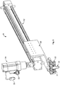
- Fig. 3 shows a cable transfer 8 for use in a harness making device 1 according to the invention.
- the cable transfer 8 comprises four cable transfer grippers 22, which hold a cable 32 with a loop 34.
- the cable transfer grippers 22 are fastened to a cable transfer slide 50 arranged above them.
- the cable transfer slide 50 is held by a cable transfer rail 52, which extends diagonally upwards and on which said slide is displaceable.
- a third servo motor 54 which moves the cable transfer slide 50, for example via a toothed belt (not shown) along the cable transfer rail 52, in order to transfer the cable 32 from the loop-layer 12 (not shown in Fig. 3 ) to the pivoting gripping device 6 (not shown in Fig. 3 ).
- Control and supply cables 55 are attached to the third servo motor 54 to supply current and control signals to the cable transfer 8.
- Fig. 4 shows a loop-layer 12 for use in a harness making device 1 according to the invention.
- the loop-layer 12 comprises a fixed gripper 26, and a movable gripper 28 to the right thereof.
- the two grippers 26, 28 hold a cable 32 with a loop 34.
- the fixed gripper 26 is mounted fixedly on the on the rail 58 of the loop-layer 12.
- the movable gripper 28 is mounted on a slide 56, which is mounted on the rail 58 and movable along the rail.
- a fourth servo motor 60 At the right-hand end of the rail 58, below the rail 58, is arranged a fourth servo motor 60, which drives the slide 56, for example by use of a toothed belt (not shown).
- Control and supply cables 61 are attached to the fourth servo motor 60 to supply current and control signals to the loop-layer 12.
- a fastener 59 is provided below the rail 58 in order to fasten the loop-layer to, for example, a frame.
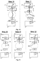
- Fig. 5 to 12 show method steps for the production of cable harnesses.
- Fig. 5 shows, in steps 1 to 4, the measuring off of the desired cable length and the laying down of the loop 34 in the loop-layer 12.
- the movable gripper 28 is guided up against the fixed gripper 26.
- the loop-layer 12 is positioned in such a way as to lie against a cutting knife 62.
- a cable 32 is guided through between the blades of a cutting knife 62, into the open grippers 26, 28 of the loop-layer 12, by the cable preparation device 10.
- the movable gripper 28 is closed and has been distanced from the fixed gripper 26 in accordance with the desired cable length.
- the fixed gripper 26 is opened again.
- the loop-layer 12 has been distanced somewhat from the cutting knife 62, in such a way that a piece of the cable remains between the cutting knife 62 and the fixed gripper 26.
- the cable 32 is fixed by closing the fixed gripper 26.
- the cable 32 is cut to the desired length.
- a cable hold-down 30 is introduced into the region between the fixed gripper 26 and the movable gripper 28, to hold the cable down.
- the movable gripper 28 is moved onto the fixed gripper 26, both of the grippers 26, 28 being closed. In this way, the cable 32 forms a loop 34 in cooperation with the cable hold-down 30.
- two cable transfer grippers 22 are moved to either side of the movable gripper 28 and the fixed gripper 26.
- the distance between the cable transfer grippers 22 is dimensioned in such a way that the movable gripper 28 and the fixed gripper 26 each fit between two cable transfer grippers 22.
- Fig. 6 shows, in steps 6 to 8, the transfer by the cable transfer 8 of a cable prepared by the loop-layer 12.
- the gripping arms of the transfer grippers 22 are closed and the fixed gripper 26 and the movable gripper 28 of the loop-layer 12 are opened.
- the cable 32 is transferred from the loop-layer 12 in the direction of the connection mechanism 2, 3 (not shown) by the cable transfer grippers 22.
- the cable transfer grippers 22 have positioned the cable 32 in the still open gripping arms 14, 16 of the pivoting gripping device 6 between the receiving positions 7, 9.
- the distance between the cable transfer grippers 22 is dimensioned in such a way that a gripping arm 14, 16 of the pivoting gripping device 6 fits between two cable transfer grippers 22 in each case.
- the gripping arms 14, 16 of the pivoting gripping device 6 are closed in order to hold the cable 32, and the cable transfer grippers 22 are opened in order to release the cable 32.
- the cable transfer grippers 22 are moved out of the region of the pivoting gripping device 6.
- Fig. 7 shows the connection of the two ends of the cable 32 to the connectors 4, 5 in the connection mechanism 2, 3 for the production of what is known as a jumper connection.
- the connectors 4, 5 are arranged in the connection mechanism 2, 3 in such a way that the first receiving positions 4a, 5a thereof lie opposite the ends of the cable 32.
- the gripping arms 14, 16 are moved in the direction of the connection mechanism 2, 3 in such a way that the cable ends 32a, 32b are introduced into the connectors 4, 5.
- the cable ends 32a, 32b are connected to the connectors 4, 5 in a step not shown in Fig. 7 .
- the gripping arms 14, 16 of the pivoting gripping device 6 are opened in order to release the cable 32 and moved back into the starting position to receive a further cable 32.
- the connectors 4, 5 are displaced within the connection mechanism 2, 3 perpendicular to the extension of the cable 32 in such a way that in the next step, the ends of the cable 32 are arranged opposite two receiving positions 4b and 5b. In this way, respectively opposite connection positions of the connectors 4, 5 are connected by a cable 32.
- the method shown in Fig. 8 follows on from the ninth step shown in Fig. 6 and represents a method for the production of a bridge connection.
- the second gripping arm 16 remains in the starting position thereof.
- the first gripping arm 14 is released and moved into the starting position thereof, whilst the second gripping arm 16 remains closed.
- the gripping arms 14, 16 together perform a 180° rotation about an axis, A, lying in between them, in such a way as to swap positions.
- the first connector 4 is displaced in a plane perpendicular to the cable 32 by the first connection mechanism 2 in such a way that the second cable end 32b of the cable 32 is positioned opposite a second receiving position 4b of the first connector 4.
- the second gripping arm 16 is moved in the direction towards the first connection mechanism 2 in such a way that the second cable end 32b of the cable 32 is introduced into the second receiving position 4b of the first connector 4.
- the second cable end 32b of the cable 32 is connected to the second receiving position 4b of the first connector 4 by the first connection mechanism 2, in order to construct a bridge connection on the first connector 4.
- the second gripping arm 16 is opened and the two grippers are rotated once again by 180° about the common axis A in order to restore the starting position.
- Fig. 9 likewise follows on from the ninth step shown in Fig. 6 and shows a method for the production of crossover connections.
- the second connector 5 is moved to the left by the second connection mechanism 3 in such a way that the second cable end 32b is positioned opposite a second receiving position 5b of the second connector 5.
- the gripping arms 14, 16 are each moved in the direction of the connection mechanism 2, 3 in such a way that the first cable end 32a is introduced into the first receiving position 4a of the first connector 4 and the second cable end 32b is introduced into the second receiving position 5b of the second connector 5. Thereupon, the first cable end 32a is connected to the first receiving position 4a of the first connector 4 and the second cable end 32b is connected to the second receiving position 5b of the second connector 5.
- the gripping arms 14, 16 of the pivoting gripping device 6 are opened in such a way as to release the cable 32, and are moved into the starting position.
- the first connector 4 is moved to the left by the first connection mechanism 2 in such a way that a second receiving position 4b of the first connector 4 is positioned in front of the first gripping arm 14.
- the second connector 5 is moved to the right by the second connection mechanism 3 in such a way that the first receiving position 5a of the second connector 5 is positioned in front of the second gripping arm 16.
- the next figure, for the thirteenth step shows the state after a second cable 32 has been connected between the second receiving position 4b of the first connector 4 and the first receiving position 5a of the second connector 5 in such a way that a cable harness with a crossover has been produced.
- the method shown in Fig. 10 likewise follows on from the ninth step shown in Fig. 6 and represents a method for the production of a cable harness with a free end.
- Cable harnesses of this type can be produced with short cable lengths of less than 60 mm, preferably less than 50 mm.
- the first gripping arm 14 is moved in the direction of the first connection mechanism 2 in such a way that the first cable end 32a is introduced into a first receiving position 4a of the first connector 4 and fastened there.
- the second gripping arm 16 remains in the starting position thereof.
- the gripping arms 14 and 16 are opened in such a way as to release the cable 32.
- the second gripping arm 16 drops the second cable end 32b of the cable 32.
- a cable harness of this type may alternatively also be produced using the second connection mechanism 3.
- the method shown in Fig. 11 likewise follows on from the ninth step shown in Fig. 6 and represents a method for fastening a short cable with a free end.
- the short cable 32 is held only by the first gripping arm 14.
- a first receiving position 4a of the first connector 4 is arranged opposite the first cable end 32a of the short cable 32.
- the first gripping arm 14 is moved in the direction of the first connection mechanism 2, in such a way that the first cable end 32a is introduced into the first receiving position 4a of the first connector 4 and fastened there.
- the first gripping arm 14 is opened and moved into the starting position.
- the second cable end 32b of the short cable 32 is dropped.
- Fig. 12 shows an alternative method, which likewise follows on from the ninth step shown in Fig. 6 , for the connection of a short cable 32 with a free end.
- the short cable 32 is held only by the first gripping arm 14.
- the first and second gripping arms 14, 16 are rotated together by 180° about an axis A lying there between, in such a way as to swap positions.
- the first cable end 32a is thus positioned opposite a first receiving position 5a of a second connector 5 in the second connection mechanism 3.
- the first gripping arm 14 is moved in the direction of the second connection mechanism 3 in such a way that the first cable end 32a is introduced into the first receiving position 5a of the second connector 5 and connected thereto.
- the first gripping arm 14 is opened.
- the second cable end 32b of the cable 32 is dropped.
- the first and second gripping arm 14, 16 are rotated back about the common axis A thereof into the starting position.
- Fig. 13 shows three different examples of cable harnesses.
- Fig. 13a shows cable harnesses with one-sided contact, i.e. with free ends and bridges.
- the first connector 4 on the left-hand side comprises a bridge 63 between the receiving positions 4b and 4c.
- Two cables 32 with free ends are fastened in the first receiving position 4a.
- a cable 32 with a free end is fastened in the receiving position 4d.
- the second connector 5 shown on the right-hand side, comprises a cable 32 with a free end in each of the receiving positions 5a, 5c and 5d.
- a bridge 63 is formed between the receiving positions 5b and 5c.
- the cable harness shown in Fig. 13b comprises a jumper connection between the receiving positions 4e and 5e.
- the receiving positions 4c and 5d, as well as 4d and 5c, are connected to one another with a crossover connection.
- the second receiving position 4b is connected to the receiving position 5a.
- the receiving positions 4a and 5b each comprise cable 32 with a free end.
- Fig. 13c shows a cable harness with two-sided contact and bridge connections.
- the first receiving position 4a is connected to the receiving position 5d by a cable 32.
- the second receiving position 4b is connected to the receiving position 5f by a cable 32.
- the first connecter 4 further comprises a bridge connection in each case between the receiving positions 4c and 4d and between the receiving positions 4e and 4f.
- the second connector 5 comprises a bridge connection between the receiving positions 5a and 5b and a bridge connection between the receiving positions 5c and 5e.
Landscapes
- Engineering & Computer Science (AREA)
- Manufacturing & Machinery (AREA)
- Manufacturing Of Electrical Connectors (AREA)
- Processing Of Terminals (AREA)
- Wire Processing (AREA)
Description
- The invention relates to a harness making device, a pivoting gripping device, and a cable preparation device for use in a harness making device of this type, as well as a method for the production of cable harnesses.
- Harness making devices for the automatic construction of cable harnesses, such as those used, for example, in "white goods", are known from the state of the art. In harness making devices of this type, cables are pulled from a supply, usually a cable drum, in a desired length by a robot arm and introduced to connection devices, in which said cables are connected to cable connectors. Because the robot arm requires considerable operating space, it is not possible for a plurality of connection devices to be arranged close together. Thus, the known harness making devices generally cannot produce cable harnesses with especially short cable lengths.
US 5 159 749 A discloses a harness making device according to the preamble ofclaim 1. An object of the present invention is therefore to provide a harness making device and a method, for the production of cable harnesses, so that cable harnesses with especially short cable lengths can be produced efficiently. - This object is achieved by a harness making device according to the
independent claim 1 and a method for the production of cable harnesses according toclaim 22. The invention further relates to a pivoting gripping device according toclaim 16 and a cable preparation device according to claim 21 for use in a harness making device of this type for the production of cable harnesses. - The pivoting gripping device in a harness making device according to the
independent claim 1 is arranged in a fixed position between two receiving positions for each at least one connection mechanism, and the cables are introduced to the pivoting gripping device by a cable transfer. Accordingly, the pivoting gripping device requires little lateral space, in such a way that at least two receiving positions can be arranged opposite one another at a small distance. It is thus possible, with a harness making device according to the invention, to produce cable harnesses with an especially short cable length. - In one embodiment, the distance between the receiving positions is no more than 150 mm, preferably no more than 140 mm.
- In a further embodiment, the harness making device is constructed for the production of plug connections, in particular for the production of IDC connections, such as those frequently used in cable harnesses.
- In a further embodiment, the connection mechanism is constructed in such a way that the connector(s) used can be moved in a plane which is perpendicular to the end portion of the cable, so that the end portion of the cable can optionally be positioned in front of one of a plurality of receiving positions of the connector. In this way, it is possible to produce various cable harnesses with different wiring patterns in a simple manner.
- In one possible embodiment, the pivoting gripping device comprises at least one gripping arm, which in turn comprises an actuator, the gripping arm being movable via actuation of the actuator by one of the connection mechanisms. The gripping arm can thus be moved by the connection mechanism without the pivoting gripping device having to have its own drive for moving the gripping arm.
- In a further embodiment, the gripping arm is rotatable in a plane which lies parallel to the end portion of the cable. In this way, both ends of the cable can be connected with the same connector when using a connection mechanism. Particularly, the gripping arm is movable independently from the cable transfer and from the cable preparation device.
- In one embodiment, the harness making device is constructed in such a way that the introduction and connection of at least one end portion of a first cable can be carried out simultaneously with the transfer of a second cable and simultaneously with the preparation of a third cable. In this way, the harness making device can be operated particularly efficiently and a large number of cable harnesses can be produced per unit time.
- The invention further comprises a pivoting gripping device for use in a harness making device according to the invention, said harness making device comprising a first servo motor, to move the at least one gripping arm parallel to the end portion of the cable, and a swivel drive, to turn the pivoting gripping device. In this case, the swivel drive is attached vertically above or below the servo motor. In this way, the pivoting gripping device can be produced so as to be particularly compact, i.e. with a small width, so that the receiving positions can be close together, enabling the production of cable harnesses with especially short cable lengths.
- The invention also comprises a cable preparation device for use in a harness making device according to the invention, which comprises a loop-layer for measuring off the desired cable length.
- In one embodiment, the loop-layer comprises a cable hold-down, to hold the cable down when laying down the loop. This ensures that the loop is formed in a defined direction, increasing the reliability and operating safety of the loop-layer.
- Further embodiments may be taken from the sub-claims.
- The invention will be explained in greater detail in the following by way of the embodiments shown in the appended figures, in which:
-
Figure 1 is a schematic representation, in a plan view, of a harness making device according to the invention; -
Figure 2 is a perspective view of a pivoting gripping device for use in a harness making device according to the invention; -
Figure 3 is a perspective view of a cable transfer for use in a harness making device according to the invention; -
Figure 4 is a perspective view of a loop-layer for use in a harness making device according to the invention; -
Figures 5 to 12 show method steps for the production of cable harnesses; and -
Figure 13 shows examples of connection diagrams for various cable harnesses. -
Fig. 1 is a schematic representation, in a plan view, of a harness makingdevice 1 according to the invention. The upper region ofFig. 1 schematically shows an arrangement of fourcable drums 40, from which thecable 32, used for the production of the cable harnesses, is removed by acable preparation device 10 arranged underneath. Thecable preparation device 10 comprises a loop-layer 12, which produces a cable portion of the desired length and forms a cable loop. Thecable 32 prepared in this manner is taken up by thecable transfer 8, which is arranged to the left of the loop-layer 12 and extends horizontally, and transferred to the pivotinggripping device 6. On each of the two sides of the pivoting gripping device 6 (above and below the pivotinggripping device 6 in the plan view shown inFig. 1 ), areceiving position connection mechanism connector - The
pivoting gripping device 6 positions the two ends of thecable 32, which have been delivered by thecable transfer 8, in front of the desired receiving positions of theconnectors connector connection mechanism - The distance between the two connectors, i.e. the cable length of the cable harness produced, is 140 mm in the embodiment shown in
Fig. 1 . - The procedure just described for the preparation of a
cable 32 by thecable preparation device 10, the delivery of the preparedcable 32 to the pivotinggripping device 6 by thecable transfer 8, and the positioning of the ends of thecable 32 in front of the receiving positions of theconnectors pivoting gripping device 6, as well as the connection of the ends of thecable 32 to theconnectors connection mechanism cables 32 to be produced. Subsequently, the produced cable harness is released into thecable harness outlet 42. -
Fig. 2 is a perspective view of a pivotinggripping device 6 for use in a harness makingdevice 1 according to the invention. In the region shown below inFig. 2 , the pivotinggripping device 6 has two grippingarms gripping arms actuators connection mechanism 2, 3 (not shown inFig. 2 ) can engage in order to move thegripping arm arms holding plate 44 in such a way as to be laterally displaceable. On theholding plate 44 are disposed twofirst servo motors respective gripping arm - On the
holding plate 44 is arranged aframe 46, which is rotatably connected to aswivel drive 38, which is arranged above theframe 46. Above theswivel drive 38 is arranged asecond servo motor 48, to drive theswivel drive 38 and thus to rotate theframe 46 together with thefirst servo motor 36, theholding plate 44 and the grippingarms - Control and
supply cables 49 are attached to thesecond servo motor 48, in order to supply current and control signals to the pivotinggripping device 6. - With the vertical construction shown in
Fig. 2 , in which thegripping arms first servo motors swivel drive 38 and thesecond servo motor 48 are arranged vertically with respect to one another, the pivotinggripping device 6 has a small width, in such a way that the arrangement can even be used between receivingpositions -
Fig. 3 shows acable transfer 8 for use in a harness makingdevice 1 according to the invention. In the region shown below on the left-hand side inFig. 3 , thecable transfer 8 comprises fourcable transfer grippers 22, which hold acable 32 with aloop 34. Thecable transfer grippers 22 are fastened to acable transfer slide 50 arranged above them. Thecable transfer slide 50 is held by acable transfer rail 52, which extends diagonally upwards and on which said slide is displaceable. Above thecable transfer rail 52, at the left-hand end thereof, is arranged athird servo motor 54, which moves thecable transfer slide 50, for example via a toothed belt (not shown) along thecable transfer rail 52, in order to transfer thecable 32 from the loop-layer 12 (not shown inFig. 3 ) to the pivoting gripping device 6 (not shown inFig. 3 ). - Control and
supply cables 55 are attached to thethird servo motor 54 to supply current and control signals to thecable transfer 8. -
Fig. 4 shows a loop-layer 12 for use in a harness makingdevice 1 according to the invention. In the region shown on the left inFig. 4 , the loop-layer 12 comprises afixed gripper 26, and amovable gripper 28 to the right thereof. The twogrippers cable 32 with aloop 34. The fixedgripper 26 is mounted fixedly on the on therail 58 of the loop-layer 12. Themovable gripper 28 is mounted on aslide 56, which is mounted on therail 58 and movable along the rail. At the right-hand end of therail 58, below therail 58, is arranged afourth servo motor 60, which drives theslide 56, for example by use of a toothed belt (not shown). By opening and closing thegrippers movable grippers 28, the desired length of thecable 32 can be measured off and aloop 34 can be laid down. - Control and
supply cables 61 are attached to thefourth servo motor 60 to supply current and control signals to the loop-layer 12. Afastener 59 is provided below therail 58 in order to fasten the loop-layer to, for example, a frame. -
Fig. 5 to 12 show method steps for the production of cable harnesses. -
Fig. 5 shows, insteps 1 to 4, the measuring off of the desired cable length and the laying down of theloop 34 in the loop-layer 12. In the first step, themovable gripper 28 is guided up against the fixedgripper 26. The loop-layer 12 is positioned in such a way as to lie against a cuttingknife 62. Acable 32 is guided through between the blades of a cuttingknife 62, into theopen grippers layer 12, by thecable preparation device 10. - In the second step, the
movable gripper 28 is closed and has been distanced from the fixedgripper 26 in accordance with the desired cable length. The fixedgripper 26 is opened again. Moreover, the loop-layer 12 has been distanced somewhat from the cuttingknife 62, in such a way that a piece of the cable remains between the cuttingknife 62 and the fixedgripper 26. - In the third step, the
cable 32 is fixed by closing the fixedgripper 26. By closing the blades of the cuttingknife 62, thecable 32 is cut to the desired length. In addition, a cable hold-down 30 is introduced into the region between the fixedgripper 26 and themovable gripper 28, to hold the cable down. - In the fourth step, the
movable gripper 28 is moved onto the fixedgripper 26, both of thegrippers cable 32 forms aloop 34 in cooperation with the cable hold-down 30. - In the fifth step, two
cable transfer grippers 22 are moved to either side of themovable gripper 28 and the fixedgripper 26. In the process, the distance between thecable transfer grippers 22 is dimensioned in such a way that themovable gripper 28 and the fixedgripper 26 each fit between twocable transfer grippers 22. -
Fig. 6 shows, insteps 6 to 8, the transfer by thecable transfer 8 of a cable prepared by the loop-layer 12. - In the sixth step, the gripping arms of the
transfer grippers 22 are closed and the fixedgripper 26 and themovable gripper 28 of the loop-layer 12 are opened. - In the seventh step, the
cable 32 is transferred from the loop-layer 12 in the direction of theconnection mechanism 2, 3 (not shown) by thecable transfer grippers 22. - In the eighth step, the
cable transfer grippers 22 have positioned thecable 32 in the still opengripping arms gripping device 6 between the receivingpositions cable transfer grippers 22 is dimensioned in such a way that agripping arm gripping device 6 fits between twocable transfer grippers 22 in each case. - In the ninth step, the gripping
arms gripping device 6 are closed in order to hold thecable 32, and thecable transfer grippers 22 are opened in order to release thecable 32. Thecable transfer grippers 22 are moved out of the region of the pivotinggripping device 6. -
Fig. 7 shows the connection of the two ends of thecable 32 to theconnectors connection mechanism - In the tenth step, the
connectors connection mechanism first receiving positions cable 32. The grippingarms connection mechanism connectors connectors Fig. 7 . - In the eleventh step, the gripping
arms gripping device 6 are opened in order to release thecable 32 and moved back into the starting position to receive afurther cable 32. Theconnectors connection mechanism cable 32 in such a way that in the next step, the ends of thecable 32 are arranged opposite two receivingpositions connectors cable 32. - The method shown in
Fig. 8 follows on from the ninth step shown inFig. 6 and represents a method for the production of a bridge connection. - In the tenth step, only the first
gripping arm 14 is displaced in the direction of thefirst connection mechanism 2, in such a way that thefirst cable end 32a of thecable 32 is introduced into afirst receiving position 4a of thefirst connector 4 and connected thereto. - The second
gripping arm 16 remains in the starting position thereof. - In the eleventh step, the first
gripping arm 14 is released and moved into the starting position thereof, whilst the secondgripping arm 16 remains closed. - In the twelfth step, the gripping
arms first connector 4 is displaced in a plane perpendicular to thecable 32 by thefirst connection mechanism 2 in such a way that thesecond cable end 32b of thecable 32 is positioned opposite asecond receiving position 4b of thefirst connector 4. - In the thirteenth step, the second
gripping arm 16 is moved in the direction towards thefirst connection mechanism 2 in such a way that thesecond cable end 32b of thecable 32 is introduced into thesecond receiving position 4b of thefirst connector 4. Thesecond cable end 32b of thecable 32 is connected to thesecond receiving position 4b of thefirst connector 4 by thefirst connection mechanism 2, in order to construct a bridge connection on thefirst connector 4. - In the fourteenth step, the second
gripping arm 16 is opened and the two grippers are rotated once again by 180° about the common axis A in order to restore the starting position. -
Fig. 9 likewise follows on from the ninth step shown inFig. 6 and shows a method for the production of crossover connections. - In the tenth step, the
second connector 5 is moved to the left by thesecond connection mechanism 3 in such a way that thesecond cable end 32b is positioned opposite asecond receiving position 5b of thesecond connector 5. - In the eleventh step, the gripping
arms connection mechanism first cable end 32a is introduced into thefirst receiving position 4a of thefirst connector 4 and thesecond cable end 32b is introduced into thesecond receiving position 5b of thesecond connector 5. Thereupon, thefirst cable end 32a is connected to thefirst receiving position 4a of thefirst connector 4 and thesecond cable end 32b is connected to thesecond receiving position 5b of thesecond connector 5. - In the twelfth step, the gripping
arms gripping device 6 are opened in such a way as to release thecable 32, and are moved into the starting position. - The
first connector 4 is moved to the left by thefirst connection mechanism 2 in such a way that asecond receiving position 4b of thefirst connector 4 is positioned in front of the firstgripping arm 14. Thesecond connector 5 is moved to the right by thesecond connection mechanism 3 in such a way that thefirst receiving position 5a of thesecond connector 5 is positioned in front of the secondgripping arm 16. - The next figure, for the thirteenth step, shows the state after a
second cable 32 has been connected between thesecond receiving position 4b of thefirst connector 4 and thefirst receiving position 5a of thesecond connector 5 in such a way that a cable harness with a crossover has been produced. - The method shown in
Fig. 10 likewise follows on from the ninth step shown inFig. 6 and represents a method for the production of a cable harness with a free end. - Cable harnesses of this type can be produced with short cable lengths of less than 60 mm, preferably less than 50 mm.
- In the tenth step, the first
gripping arm 14 is moved in the direction of thefirst connection mechanism 2 in such a way that thefirst cable end 32a is introduced into afirst receiving position 4a of thefirst connector 4 and fastened there. The secondgripping arm 16 remains in the starting position thereof. - In the eleventh step, the gripping
arms cable 32. In particular, the secondgripping arm 16 drops thesecond cable end 32b of thecable 32. - By displacing the
connector 4 by means of theconnection mechanism 2 and repeatingsteps connector 4 and cable ends 32b is produced. - A cable harness of this type may alternatively also be produced using the
second connection mechanism 3. - The method shown in
Fig. 11 likewise follows on from the ninth step shown inFig. 6 and represents a method for fastening a short cable with a free end. - In the tenth step, the
short cable 32 is held only by the firstgripping arm 14. Afirst receiving position 4a of thefirst connector 4 is arranged opposite thefirst cable end 32a of theshort cable 32. - In the eleventh step, the first
gripping arm 14 is moved in the direction of thefirst connection mechanism 2, in such a way that thefirst cable end 32a is introduced into thefirst receiving position 4a of thefirst connector 4 and fastened there. - In the twelfth step, the first
gripping arm 14 is opened and moved into the starting position. In particular, thesecond cable end 32b of theshort cable 32 is dropped. -
Fig. 12 shows an alternative method, which likewise follows on from the ninth step shown inFig. 6 , for the connection of ashort cable 32 with a free end. - In the tenth step, the
short cable 32 is held only by the firstgripping arm 14. - In the eleventh step, the first and second
gripping arms first cable end 32a is thus positioned opposite afirst receiving position 5a of asecond connector 5 in thesecond connection mechanism 3. The firstgripping arm 14 is moved in the direction of thesecond connection mechanism 3 in such a way that thefirst cable end 32a is introduced into thefirst receiving position 5a of thesecond connector 5 and connected thereto. - In the twelfth step, the first
gripping arm 14 is opened. In particular, thesecond cable end 32b of thecable 32 is dropped. The first and secondgripping arm -
Fig. 13 shows three different examples of cable harnesses. -
Fig. 13a shows cable harnesses with one-sided contact, i.e. with free ends and bridges. Thefirst connector 4 on the left-hand side comprises abridge 63 between the receivingpositions cables 32 with free ends are fastened in thefirst receiving position 4a. Acable 32 with a free end is fastened in the receivingposition 4d. - The
second connector 5, shown on the right-hand side, comprises acable 32 with a free end in each of the receivingpositions bridge 63 is formed between the receivingpositions - The cable harness shown in
Fig. 13b comprises a jumper connection between the receivingpositions positions second receiving position 4b is connected to the receivingposition 5a. - The receiving
positions cable 32 with a free end. -
Fig. 13c shows a cable harness with two-sided contact and bridge connections. - The
first receiving position 4a is connected to the receivingposition 5d by acable 32. Thesecond receiving position 4b is connected to the receivingposition 5f by acable 32. Thefirst connecter 4 further comprises a bridge connection in each case between the receivingpositions positions second connector 5 comprises a bridge connection between the receivingpositions positions - The features, embodiments and advantages which have been disclosed in relation to the harness making device for the production of cable harnesses may also be realised by method steps for the production of a harness making device according to the invention.
Claims (15)
- Harness making device (1), comprising:at least two receiving positions (7, 9) for receiving at least one connection mechanism (2, 3) each, the connection mechanism (2, 3) in each case being provided to connect at least one end portion of at least one cable to at least one connector (4, 5);at least one gripping device (6) being arranged in a fixed position between the receiving positions (7, 9) and is constructed to guide at least one end portion of the at least one cable to at least one connection mechanism (2, 3);at least one cable preparation device (10) for the preparation of at least one cable to form a cable loop; and,at least one cable transfer (8), which is constructed to receive the at least one cable from the cable preparation device (10) and to transfer said at least one cable to the gripping device (6)characterised in thatthe gripping device (6) is a pivoting gripping device (6) comprising at least one gripping arm (14, 16), the at least one gripping arm (14, 16) being rotatable in a plane which lies parallel to the end portion of the cable and comprising an actuator (18, 20) which is configured for engagement with the at least one connection mechanism (2, 3) for allowing the connection mechanism (2, 3) to move the at least one gripping arm (14, 16) perpendicular to the plane of rotation.
- Harness making device according to claim 1, wherein the distance between the receiving positions (7, 9) is less than 150 mm, preferably less than 140 mm.
- Harness making device according to either of the preceding claims, wherein the harness making device is constructed for the production of plug connections, in particular of IDC connections.
- Harness making device according to any one of the preceding claims, wherein the connection mechanism (2, 3) is constructed to move the connector (4, 5) in a plane which is perpendicular to the end portion of the cable, so that the end portion of the cable can optionally be positioned in front of one or more receiving positions of the connector.
- Harness making device according to any one of the preceding claims, wherein the pivoting gripping device (6) comprises at least one gripping arm (14, 16), which is movable in a direction perpendicular to the end portion of the cable and/or parallel to the end portion of the cable in the direction of one of the connectors (4, 5)
- Harness making device according to claim 5, wherein the at least one gripping arm (14, 16) comprises at least one actuator (18, 20) and is movable via actuation of the actuator (18, 20) by one of the connection mechanism (2, 3).
- Harness making device according to any one of the preceding claims, wherein the cable transfer (8) comprises at least one cable transfer gripper (22), which is movable between the cable preparation device (10) and the pivoting gripping device (6), the cable transfer gripper (22) being movable in particular in a straight line,wherein the cable transfer (8) preferably comprises at least two cable transfer grippers (22), the distance between the two cable transfer grippers (22) being greater than the width of the gripper arm (14, 16) of the pivoting gripping device (6).
- Harness making device according to any one of the preceding claims, wherein the cable preparation device (10) comprises at least one loop-layer (12) for measuring off a desired cable length, wherein the loop-layer preferably comprises a fixed gripper (26) and a movable gripper (28) for gripping the cable, a loop of a cable being formed by moving the movable gripper (28) relative to the fixed gripper (26).
- Harness making device according to any one of the preceding claims, which is constructed in such a way that the guidance and connection of the at least one end portion of a first cable (32) can be carried out simultaneously with the transfer of a second cable (32), and in parallel with the preparation of a third cable (32).
- Method for the production of cable harnesses using a harness making device according to any one of claims 1 to 9, comprising the steps of:preparing a cable with the at least one cable preparation device (10);transferring the cable to the at least one pivoting gripping device (6) with the at least one cable transfer (8);guiding at least one end portion of the cable (32) to at least one connection mechanism (2, 3) with the pivoting gripping device (6); and,connecting the at least one end portion of the cable (32) to a first receiving position of a first connector (4, 5).
- Method according to claim 10, wherein the method additionally comprises the step of connecting a second end portion of the cable (32) to a receiving position of a second connector (4, 5) or to a second receiving position of the first connector (4, 5).
- Method according to claim 11, wherein the method comprises rotating the pivoting gripping device (6) before the step of connecting the second end portion of the cable (32).
- Method according to claim 12, wherein the pivoting gripping device (6) is rotated by 180°.
- Method according to any one of claims 11 to 13, wherein the method comprises a displacement of the connector (4, 5) in the direction perpendicular to the end portion of the cable (32) before the step of connecting the second end portion of the cable (32).
- Method according to any one of claims 10 to 14, wherein the step of guiding and connecting at least one end portion of a first cable (32) is carried out in parallel with the step of transferring a second cable (32), and in parallel with the step of preparing a third cable (32).
Priority Applications (1)
| Application Number | Priority Date | Filing Date | Title |
|---|---|---|---|
| PL08802351T PL2201653T3 (en) | 2007-09-21 | 2008-09-18 | Harness making device and method for the production of cable harnesses |
Applications Claiming Priority (2)
| Application Number | Priority Date | Filing Date | Title |
|---|---|---|---|
| DE102007045279A DE102007045279B4 (en) | 2007-09-21 | 2007-09-21 | Apparatus and method for producing cable harnesses |
| PCT/EP2008/007830 WO2009036979A1 (en) | 2007-09-21 | 2008-09-18 | Harness making device and method for the production of cable harnesses |
Publications (2)
| Publication Number | Publication Date |
|---|---|
| EP2201653A1 EP2201653A1 (en) | 2010-06-30 |
| EP2201653B1 true EP2201653B1 (en) | 2017-11-08 |
Family
ID=39956420
Family Applications (1)
| Application Number | Title | Priority Date | Filing Date |
|---|---|---|---|
| EP08802351.0A Not-in-force EP2201653B1 (en) | 2007-09-21 | 2008-09-18 | Harness making device and method for the production of cable harnesses |
Country Status (7)
| Country | Link |
|---|---|
| US (1) | US8082664B2 (en) |
| EP (1) | EP2201653B1 (en) |
| CN (1) | CN101803129B (en) |
| DE (1) | DE102007045279B4 (en) |
| PL (1) | PL2201653T3 (en) |
| RU (1) | RU2483405C2 (en) |
| WO (1) | WO2009036979A1 (en) |
Families Citing this family (12)
| Publication number | Priority date | Publication date | Assignee | Title |
|---|---|---|---|---|
| JP5644697B2 (en) * | 2011-06-24 | 2014-12-24 | 住友電装株式会社 | Wire harness manufacturing method, electric wire support device, and connected electric wire holding bar |
| ES2575158T3 (en) * | 2011-11-02 | 2016-06-24 | Schleuniger Holding Ag | Line Placement Device |
| KR101303880B1 (en) * | 2011-12-22 | 2013-09-04 | (주)동아엘텍 | Real time communication network structure of auto in-line aging system |
| JP6352973B2 (en) * | 2016-05-31 | 2018-07-04 | 矢崎総業株式会社 | Wire harness manufacturing method and manufacturing apparatus |
| US10494816B2 (en) * | 2016-10-13 | 2019-12-03 | Felix Sorkin | Sheathing puller |
| DE102017128295A1 (en) * | 2017-11-29 | 2019-05-29 | Rittal Gmbh & Co. Kg | Method for electrical wiring of electronic components in switchgear construction and a corresponding arrangement |
| CN108418069B (en) * | 2018-01-18 | 2019-08-30 | 吴江市申江特种线缆有限公司 | A rotary push type cable transmission device |
| CN109436412B (en) * | 2018-10-26 | 2021-05-28 | 叶懿辰 | Cable bundling three-dimensional modeling method |
| CN109494540B (en) * | 2018-12-24 | 2024-06-21 | 深圳市浩湖网络技术有限公司 | Cross line exchanging mechanism and line exchanging method thereof |
| CN112018580A (en) * | 2019-05-30 | 2020-12-01 | 泰科电子(上海)有限公司 | Wire harness assembling device and wire harness assembling method |
| EP4255697B1 (en) * | 2020-12-07 | 2026-04-22 | Polygon T.R Ltd. | Systems and methods for automatic electrical wiring |
| CN120581289A (en) * | 2024-10-11 | 2025-09-02 | 常州荫余智能科技有限公司 | Device for producing cable harnesses |
Citations (2)
| Publication number | Priority date | Publication date | Assignee | Title |
|---|---|---|---|---|
| US6289944B1 (en) * | 1999-02-23 | 2001-09-18 | Komax Holding Ag | Method and equipment for the treatment and twisting together of a conductor pair |
| EP1447888A1 (en) * | 2003-02-17 | 2004-08-18 | Komax Holding Ag | Gripper for a cable treating device |
Family Cites Families (15)
| Publication number | Priority date | Publication date | Assignee | Title |
|---|---|---|---|---|
| US4136440A (en) * | 1977-07-12 | 1979-01-30 | Amp Incorporated | Electrical harness fabrication method and apparatus |
| FR2440099A1 (en) * | 1978-10-25 | 1980-05-23 | Labinal | DEVICE FOR PLUGING ENDS OF ELECTRICAL CONDUCTORS OR THE LIKE INTO A HOUSING |
| US4310967A (en) * | 1979-02-16 | 1982-01-19 | Molex Incorporated | Apparatus for electrical harness fabrication |
| US4404743A (en) * | 1981-05-26 | 1983-09-20 | Amp Incorporated | Electrical harness fabrication using improved wire measuring method |
| US4653160A (en) * | 1982-11-10 | 1987-03-31 | Artos Engineering Company | Apparatus for making finished wire harnesses or sub-assemblies therefor |
| SU1693673A1 (en) * | 1989-01-18 | 1991-11-23 | Новосибирский электротехнический институт | Device for splicing and terminating wire and cable conductors |
| GB9001999D0 (en) * | 1990-01-29 | 1990-03-28 | Amp Gmbh | Wire transfer device for lead making machine |
| DE9204203U1 (en) * | 1992-03-25 | 1993-07-22 | Siemens AG, 80333 München | Assembly device |
| FR2721445B1 (en) * | 1994-06-15 | 1996-09-13 | Ind Entreprise | Machine for manufacturing electrical harnesses comprising simple connectors and its use. |
| DE4431254A1 (en) * | 1994-09-02 | 1996-03-07 | Broekelmann Jaeger & Busse | Method and device for wiring connection points of components of electrical devices |
| DE29502257U1 (en) * | 1995-02-11 | 1995-03-30 | Jährig, Mike, Dipl.-Ing., 02625 Bautzen | Network |
| JP2992678B2 (en) * | 1996-06-14 | 1999-12-20 | モレックス インコーポレーテッド | Wire draw-out mechanism of wire draw-out part in wire pressure welding device |
| DE19750690C2 (en) * | 1997-11-15 | 2001-12-13 | Broekelmann, Jaeger & Busse Gmbh & Co | Method and device for the automatic wiring of connection points of components of electrical devices |
| DE19756750C1 (en) * | 1997-12-19 | 1999-08-19 | Broekelmann | Device for wiring connection points of components of electrical devices or systems |
| RU2231186C2 (en) * | 2002-08-09 | 2004-06-20 | Москаленко Юрий Сергеевич | Multipurpose tool for assembly of current conducting conductors of multipair electric communication cables with their connectors |
-
2007
- 2007-09-21 DE DE102007045279A patent/DE102007045279B4/en not_active Expired - Fee Related
-
2008
- 2008-09-18 PL PL08802351T patent/PL2201653T3/en unknown
- 2008-09-18 RU RU2010113727/07A patent/RU2483405C2/en not_active IP Right Cessation
- 2008-09-18 WO PCT/EP2008/007830 patent/WO2009036979A1/en not_active Ceased
- 2008-09-18 CN CN2008801082088A patent/CN101803129B/en not_active Expired - Fee Related
- 2008-09-18 EP EP08802351.0A patent/EP2201653B1/en not_active Not-in-force
-
2010
- 2010-03-19 US US12/727,942 patent/US8082664B2/en not_active Expired - Fee Related
Patent Citations (2)
| Publication number | Priority date | Publication date | Assignee | Title |
|---|---|---|---|---|
| US6289944B1 (en) * | 1999-02-23 | 2001-09-18 | Komax Holding Ag | Method and equipment for the treatment and twisting together of a conductor pair |
| EP1447888A1 (en) * | 2003-02-17 | 2004-08-18 | Komax Holding Ag | Gripper for a cable treating device |
Also Published As
| Publication number | Publication date |
|---|---|
| DE102007045279A1 (en) | 2009-04-09 |
| PL2201653T3 (en) | 2018-03-30 |
| RU2483405C2 (en) | 2013-05-27 |
| US8082664B2 (en) | 2011-12-27 |
| RU2010113727A (en) | 2011-10-27 |
| DE102007045279B4 (en) | 2009-06-18 |
| WO2009036979A1 (en) | 2009-03-26 |
| US20100186212A1 (en) | 2010-07-29 |
| CN101803129A (en) | 2010-08-11 |
| CN101803129B (en) | 2013-05-08 |
| EP2201653A1 (en) | 2010-06-30 |
Similar Documents
| Publication | Publication Date | Title |
|---|---|---|
| US8082664B2 (en) | Harness making device and method for the production of cable harnesses | |
| JPS61277115A (en) | Apparatus and method for manufacturing electric harness | |
| DE102009057013B4 (en) | Reconfigurable grippers with hinged frame and snap-in main boom | |
| US6135164A (en) | Apparatus and method for preparing wires in a harness making machine | |
| CN113964621B (en) | Refrigerator sensor wire harness production method | |
| EP1257028A2 (en) | Shearing-stripping machine for electric cables | |
| BR0212939B1 (en) | Conveyor system for interfacing with production equipment and component assembly. | |
| EP3557592A1 (en) | Device and method for twisting a first and second electrical single wire line to form a cable pair | |
| EP1342248B1 (en) | Method for producing cable harnesses and device for carrying out this method | |
| CN113964626B (en) | Branching device for refrigerator sensor wire harness production | |
| DE3820638C2 (en) | Method and device for making wire harnesses | |
| JPH07211427A (en) | Wire straightening device for wire processing machine | |
| US20250201451A1 (en) | Apparatus for manufacturing wire harness, method for manufacturing wire harness, and wire harness | |
| US20250202181A1 (en) | Tension control apparatus, apparatus for manufacturing wire harness, tension control method, and method for manufacturing wire harness | |
| EP0817329A1 (en) | Apparatus for making wire harnesses | |
| WO2021191671A1 (en) | Cable manipulation head and system for automatically routing cables along a preset path | |
| EP0993085A2 (en) | Electric wire grasping clamp | |
| EP0356252A2 (en) | Double-ended termination and routing arrangement for an automated wiring system | |
| JP3181291B2 (en) | Wire gripper and method and apparatus for manufacturing wire bundle using gripper | |
| JP3077546B2 (en) | Wire bundle assembly intake device | |
| US20100170089A1 (en) | Automated wiring apparatus and method | |
| CN113752195B (en) | A lead positioner for sensor pencil production | |
| CN111091934B (en) | One-point multi-harness clamping method | |
| CN119786157B (en) | A transfer device and a stranding machine | |
| JPH07500211A (en) | Method and device for inserting wire into parts and device for making wire bundles |
Legal Events
| Date | Code | Title | Description |
|---|---|---|---|
| PUAI | Public reference made under article 153(3) epc to a published international application that has entered the european phase |
Free format text: ORIGINAL CODE: 0009012 |
|
| 17P | Request for examination filed |
Effective date: 20100420 |
|
| AK | Designated contracting states |
Kind code of ref document: A1 Designated state(s): AT BE BG CH CY CZ DE DK EE ES FI FR GB GR HR HU IE IS IT LI LT LU LV MC MT NL NO PL PT RO SE SI SK TR |
|
| AX | Request for extension of the european patent |
Extension state: AL BA MK RS |
|
| DAX | Request for extension of the european patent (deleted) | ||
| RAP1 | Party data changed (applicant data changed or rights of an application transferred) |
Owner name: TE CONNECTIVITY GERMANY GMBH |
|
| 17Q | First examination report despatched |
Effective date: 20151007 |
|
| GRAP | Despatch of communication of intention to grant a patent |
Free format text: ORIGINAL CODE: EPIDOSNIGR1 |
|
| INTG | Intention to grant announced |
Effective date: 20170413 |
|
| GRAS | Grant fee paid |
Free format text: ORIGINAL CODE: EPIDOSNIGR3 |
|
| GRAJ | Information related to disapproval of communication of intention to grant by the applicant or resumption of examination proceedings by the epo deleted |
Free format text: ORIGINAL CODE: EPIDOSDIGR1 |
|
| GRAL | Information related to payment of fee for publishing/printing deleted |
Free format text: ORIGINAL CODE: EPIDOSDIGR3 |
|
| GRAR | Information related to intention to grant a patent recorded |
Free format text: ORIGINAL CODE: EPIDOSNIGR71 |
|
| INTC | Intention to grant announced (deleted) | ||
| GRAA | (expected) grant |
Free format text: ORIGINAL CODE: 0009210 |
|
| INTG | Intention to grant announced |
Effective date: 20170912 |
|
| AK | Designated contracting states |
Kind code of ref document: B1 Designated state(s): AT BE BG CH CY CZ DE DK EE ES FI FR GB GR HR HU IE IS IT LI LT LU LV MC MT NL NO PL PT RO SE SI SK TR |
|
| REG | Reference to a national code |
Ref country code: GB Ref legal event code: FG4D |
|
| REG | Reference to a national code |
Ref country code: CH Ref legal event code: EP Ref country code: AT Ref legal event code: REF Ref document number: 945026 Country of ref document: AT Kind code of ref document: T Effective date: 20171115 |
|
| REG | Reference to a national code |
Ref country code: IE Ref legal event code: FG4D |
|
| REG | Reference to a national code |
Ref country code: DE Ref legal event code: R096 Ref document number: 602008052885 Country of ref document: DE |
|
| REG | Reference to a national code |
Ref country code: RO Ref legal event code: EPE |
|
| REG | Reference to a national code |
Ref country code: NL Ref legal event code: MP Effective date: 20171108 |
|
| REG | Reference to a national code |
Ref country code: LT Ref legal event code: MG4D |
|
| REG | Reference to a national code |
Ref country code: AT Ref legal event code: MK05 Ref document number: 945026 Country of ref document: AT Kind code of ref document: T Effective date: 20171108 |
|
| PG25 | Lapsed in a contracting state [announced via postgrant information from national office to epo] |
Ref country code: SE Free format text: LAPSE BECAUSE OF FAILURE TO SUBMIT A TRANSLATION OF THE DESCRIPTION OR TO PAY THE FEE WITHIN THE PRESCRIBED TIME-LIMIT Effective date: 20171108 Ref country code: NO Free format text: LAPSE BECAUSE OF FAILURE TO SUBMIT A TRANSLATION OF THE DESCRIPTION OR TO PAY THE FEE WITHIN THE PRESCRIBED TIME-LIMIT Effective date: 20180208 Ref country code: ES Free format text: LAPSE BECAUSE OF FAILURE TO SUBMIT A TRANSLATION OF THE DESCRIPTION OR TO PAY THE FEE WITHIN THE PRESCRIBED TIME-LIMIT Effective date: 20171108 Ref country code: NL Free format text: LAPSE BECAUSE OF FAILURE TO SUBMIT A TRANSLATION OF THE DESCRIPTION OR TO PAY THE FEE WITHIN THE PRESCRIBED TIME-LIMIT Effective date: 20171108 Ref country code: FI Free format text: LAPSE BECAUSE OF FAILURE TO SUBMIT A TRANSLATION OF THE DESCRIPTION OR TO PAY THE FEE WITHIN THE PRESCRIBED TIME-LIMIT Effective date: 20171108 Ref country code: LT Free format text: LAPSE BECAUSE OF FAILURE TO SUBMIT A TRANSLATION OF THE DESCRIPTION OR TO PAY THE FEE WITHIN THE PRESCRIBED TIME-LIMIT Effective date: 20171108 |
|
| PG25 | Lapsed in a contracting state [announced via postgrant information from national office to epo] |
Ref country code: AT Free format text: LAPSE BECAUSE OF FAILURE TO SUBMIT A TRANSLATION OF THE DESCRIPTION OR TO PAY THE FEE WITHIN THE PRESCRIBED TIME-LIMIT Effective date: 20171108 Ref country code: BG Free format text: LAPSE BECAUSE OF FAILURE TO SUBMIT A TRANSLATION OF THE DESCRIPTION OR TO PAY THE FEE WITHIN THE PRESCRIBED TIME-LIMIT Effective date: 20180208 Ref country code: IS Free format text: LAPSE BECAUSE OF FAILURE TO SUBMIT A TRANSLATION OF THE DESCRIPTION OR TO PAY THE FEE WITHIN THE PRESCRIBED TIME-LIMIT Effective date: 20180308 Ref country code: GR Free format text: LAPSE BECAUSE OF FAILURE TO SUBMIT A TRANSLATION OF THE DESCRIPTION OR TO PAY THE FEE WITHIN THE PRESCRIBED TIME-LIMIT Effective date: 20180209 Ref country code: LV Free format text: LAPSE BECAUSE OF FAILURE TO SUBMIT A TRANSLATION OF THE DESCRIPTION OR TO PAY THE FEE WITHIN THE PRESCRIBED TIME-LIMIT Effective date: 20171108 Ref country code: HR Free format text: LAPSE BECAUSE OF FAILURE TO SUBMIT A TRANSLATION OF THE DESCRIPTION OR TO PAY THE FEE WITHIN THE PRESCRIBED TIME-LIMIT Effective date: 20171108 |
|
| PG25 | Lapsed in a contracting state [announced via postgrant information from national office to epo] |
Ref country code: SK Free format text: LAPSE BECAUSE OF FAILURE TO SUBMIT A TRANSLATION OF THE DESCRIPTION OR TO PAY THE FEE WITHIN THE PRESCRIBED TIME-LIMIT Effective date: 20171108 Ref country code: EE Free format text: LAPSE BECAUSE OF FAILURE TO SUBMIT A TRANSLATION OF THE DESCRIPTION OR TO PAY THE FEE WITHIN THE PRESCRIBED TIME-LIMIT Effective date: 20171108 Ref country code: CY Free format text: LAPSE BECAUSE OF FAILURE TO SUBMIT A TRANSLATION OF THE DESCRIPTION OR TO PAY THE FEE WITHIN THE PRESCRIBED TIME-LIMIT Effective date: 20171108 Ref country code: DK Free format text: LAPSE BECAUSE OF FAILURE TO SUBMIT A TRANSLATION OF THE DESCRIPTION OR TO PAY THE FEE WITHIN THE PRESCRIBED TIME-LIMIT Effective date: 20171108 |
|
| REG | Reference to a national code |
Ref country code: DE Ref legal event code: R097 Ref document number: 602008052885 Country of ref document: DE |
|
| PG25 | Lapsed in a contracting state [announced via postgrant information from national office to epo] |
Ref country code: IT Free format text: LAPSE BECAUSE OF FAILURE TO SUBMIT A TRANSLATION OF THE DESCRIPTION OR TO PAY THE FEE WITHIN THE PRESCRIBED TIME-LIMIT Effective date: 20171108 |
|
| PLBE | No opposition filed within time limit |
Free format text: ORIGINAL CODE: 0009261 |
|
| STAA | Information on the status of an ep patent application or granted ep patent |
Free format text: STATUS: NO OPPOSITION FILED WITHIN TIME LIMIT |
|
| 26N | No opposition filed |
Effective date: 20180809 |
|
| PG25 | Lapsed in a contracting state [announced via postgrant information from national office to epo] |
Ref country code: SI Free format text: LAPSE BECAUSE OF FAILURE TO SUBMIT A TRANSLATION OF THE DESCRIPTION OR TO PAY THE FEE WITHIN THE PRESCRIBED TIME-LIMIT Effective date: 20171108 |
|
| PGFP | Annual fee paid to national office [announced via postgrant information from national office to epo] |
Ref country code: FR Payment date: 20180725 Year of fee payment: 17 |
|
| REG | Reference to a national code |
Ref country code: DE Ref legal event code: R119 Ref document number: 602008052885 Country of ref document: DE |
|
| PG25 | Lapsed in a contracting state [announced via postgrant information from national office to epo] |
Ref country code: MC Free format text: LAPSE BECAUSE OF FAILURE TO SUBMIT A TRANSLATION OF THE DESCRIPTION OR TO PAY THE FEE WITHIN THE PRESCRIBED TIME-LIMIT Effective date: 20171108 |
|
| REG | Reference to a national code |
Ref country code: CH Ref legal event code: PL |
|
| GBPC | Gb: european patent ceased through non-payment of renewal fee |
Effective date: 20180918 |
|
| REG | Reference to a national code |
Ref country code: BE Ref legal event code: MM Effective date: 20180930 |
|
| REG | Reference to a national code |
Ref country code: IE Ref legal event code: MM4A |
|
| PG25 | Lapsed in a contracting state [announced via postgrant information from national office to epo] |
Ref country code: LU Free format text: LAPSE BECAUSE OF NON-PAYMENT OF DUE FEES Effective date: 20180918 |
|
| PG25 | Lapsed in a contracting state [announced via postgrant information from national office to epo] |
Ref country code: IE Free format text: LAPSE BECAUSE OF NON-PAYMENT OF DUE FEES Effective date: 20180918 Ref country code: DE Free format text: LAPSE BECAUSE OF NON-PAYMENT OF DUE FEES Effective date: 20190402 |
|
| PG25 | Lapsed in a contracting state [announced via postgrant information from national office to epo] |
Ref country code: BE Free format text: LAPSE BECAUSE OF NON-PAYMENT OF DUE FEES Effective date: 20180930 Ref country code: CH Free format text: LAPSE BECAUSE OF NON-PAYMENT OF DUE FEES Effective date: 20180930 Ref country code: FR Free format text: LAPSE BECAUSE OF NON-PAYMENT OF DUE FEES Effective date: 20180930 Ref country code: LI Free format text: LAPSE BECAUSE OF NON-PAYMENT OF DUE FEES Effective date: 20180930 |
|
| PG25 | Lapsed in a contracting state [announced via postgrant information from national office to epo] |
Ref country code: GB Free format text: LAPSE BECAUSE OF NON-PAYMENT OF DUE FEES Effective date: 20180918 |
|
| PG25 | Lapsed in a contracting state [announced via postgrant information from national office to epo] |
Ref country code: MT Free format text: LAPSE BECAUSE OF NON-PAYMENT OF DUE FEES Effective date: 20180918 |
|
| PG25 | Lapsed in a contracting state [announced via postgrant information from national office to epo] |
Ref country code: PT Free format text: LAPSE BECAUSE OF FAILURE TO SUBMIT A TRANSLATION OF THE DESCRIPTION OR TO PAY THE FEE WITHIN THE PRESCRIBED TIME-LIMIT Effective date: 20171108 Ref country code: HU Free format text: LAPSE BECAUSE OF FAILURE TO SUBMIT A TRANSLATION OF THE DESCRIPTION OR TO PAY THE FEE WITHIN THE PRESCRIBED TIME-LIMIT; INVALID AB INITIO Effective date: 20080918 |
|
| PGFP | Annual fee paid to national office [announced via postgrant information from national office to epo] |
Ref country code: RO Payment date: 20200831 Year of fee payment: 13 Ref country code: CZ Payment date: 20200909 Year of fee payment: 13 |
|
| PGFP | Annual fee paid to national office [announced via postgrant information from national office to epo] |
Ref country code: PL Payment date: 20210722 Year of fee payment: 14 |
|
| PG25 | Lapsed in a contracting state [announced via postgrant information from national office to epo] |
Ref country code: RO Free format text: LAPSE BECAUSE OF NON-PAYMENT OF DUE FEES Effective date: 20210918 Ref country code: CZ Free format text: LAPSE BECAUSE OF NON-PAYMENT OF DUE FEES Effective date: 20210918 |
|
| PG25 | Lapsed in a contracting state [announced via postgrant information from national office to epo] |
Ref country code: TR Free format text: LAPSE BECAUSE OF NON-PAYMENT OF DUE FEES Effective date: 20190918 |
|
| PG25 | Lapsed in a contracting state [announced via postgrant information from national office to epo] |
Ref country code: PL Free format text: LAPSE BECAUSE OF NON-PAYMENT OF DUE FEES Effective date: 20220918 |