EP2201254B1 - Load sensing directional control valve with an element having priority under saturation conditions - Google Patents
Load sensing directional control valve with an element having priority under saturation conditions Download PDFInfo
- Publication number
- EP2201254B1 EP2201254B1 EP20070805661 EP07805661A EP2201254B1 EP 2201254 B1 EP2201254 B1 EP 2201254B1 EP 20070805661 EP20070805661 EP 20070805661 EP 07805661 A EP07805661 A EP 07805661A EP 2201254 B1 EP2201254 B1 EP 2201254B1
- Authority
- EP
- European Patent Office
- Prior art keywords
- pressure
- flow
- compensator
- control valve
- spring
- Prior art date
- Legal status (The legal status is an assumption and is not a legal conclusion. Google has not performed a legal analysis and makes no representation as to the accuracy of the status listed.)
- Active
Links
- 230000009467 reduction Effects 0.000 claims abstract description 19
- 230000009471 action Effects 0.000 claims description 8
- 230000007423 decrease Effects 0.000 description 5
- 238000010276 construction Methods 0.000 description 3
- 230000000694 effects Effects 0.000 description 3
- 230000003247 decreasing effect Effects 0.000 description 1
- 230000004044 response Effects 0.000 description 1
- 230000001052 transient effect Effects 0.000 description 1
- 238000011144 upstream manufacturing Methods 0.000 description 1
Images


Classifications
-
- F—MECHANICAL ENGINEERING; LIGHTING; HEATING; WEAPONS; BLASTING
- F15—FLUID-PRESSURE ACTUATORS; HYDRAULICS OR PNEUMATICS IN GENERAL
- F15B—SYSTEMS ACTING BY MEANS OF FLUIDS IN GENERAL; FLUID-PRESSURE ACTUATORS, e.g. SERVOMOTORS; DETAILS OF FLUID-PRESSURE SYSTEMS, NOT OTHERWISE PROVIDED FOR
- F15B13/00—Details of servomotor systems ; Valves for servomotor systems
- F15B13/02—Fluid distribution or supply devices characterised by their adaptation to the control of servomotors
- F15B13/04—Fluid distribution or supply devices characterised by their adaptation to the control of servomotors for use with a single servomotor
- F15B13/0401—Valve members; Fluid interconnections therefor
- F15B13/0402—Valve members; Fluid interconnections therefor for linearly sliding valves, e.g. spool valves
-
- F—MECHANICAL ENGINEERING; LIGHTING; HEATING; WEAPONS; BLASTING
- F15—FLUID-PRESSURE ACTUATORS; HYDRAULICS OR PNEUMATICS IN GENERAL
- F15B—SYSTEMS ACTING BY MEANS OF FLUIDS IN GENERAL; FLUID-PRESSURE ACTUATORS, e.g. SERVOMOTORS; DETAILS OF FLUID-PRESSURE SYSTEMS, NOT OTHERWISE PROVIDED FOR
- F15B11/00—Servomotor systems without provision for follow-up action; Circuits therefor
- F15B11/16—Servomotor systems without provision for follow-up action; Circuits therefor with two or more servomotors
- F15B11/161—Servomotor systems without provision for follow-up action; Circuits therefor with two or more servomotors with sensing of servomotor demand or load
- F15B11/162—Servomotor systems without provision for follow-up action; Circuits therefor with two or more servomotors with sensing of servomotor demand or load for giving priority to particular servomotors or users
-
- F—MECHANICAL ENGINEERING; LIGHTING; HEATING; WEAPONS; BLASTING
- F15—FLUID-PRESSURE ACTUATORS; HYDRAULICS OR PNEUMATICS IN GENERAL
- F15B—SYSTEMS ACTING BY MEANS OF FLUIDS IN GENERAL; FLUID-PRESSURE ACTUATORS, e.g. SERVOMOTORS; DETAILS OF FLUID-PRESSURE SYSTEMS, NOT OTHERWISE PROVIDED FOR
- F15B11/00—Servomotor systems without provision for follow-up action; Circuits therefor
- F15B11/16—Servomotor systems without provision for follow-up action; Circuits therefor with two or more servomotors
- F15B11/161—Servomotor systems without provision for follow-up action; Circuits therefor with two or more servomotors with sensing of servomotor demand or load
- F15B11/163—Servomotor systems without provision for follow-up action; Circuits therefor with two or more servomotors with sensing of servomotor demand or load for sharing the pump output equally amongst users or groups of users, e.g. using anti-saturation, pressure compensation
-
- F—MECHANICAL ENGINEERING; LIGHTING; HEATING; WEAPONS; BLASTING
- F15—FLUID-PRESSURE ACTUATORS; HYDRAULICS OR PNEUMATICS IN GENERAL
- F15B—SYSTEMS ACTING BY MEANS OF FLUIDS IN GENERAL; FLUID-PRESSURE ACTUATORS, e.g. SERVOMOTORS; DETAILS OF FLUID-PRESSURE SYSTEMS, NOT OTHERWISE PROVIDED FOR
- F15B13/00—Details of servomotor systems ; Valves for servomotor systems
- F15B13/02—Fluid distribution or supply devices characterised by their adaptation to the control of servomotors
- F15B13/04—Fluid distribution or supply devices characterised by their adaptation to the control of servomotors for use with a single servomotor
- F15B13/0416—Fluid distribution or supply devices characterised by their adaptation to the control of servomotors for use with a single servomotor with means or adapted for load sensing
- F15B13/0417—Load sensing elements; Internal fluid connections therefor; Anti-saturation or pressure-compensation valves
-
- F—MECHANICAL ENGINEERING; LIGHTING; HEATING; WEAPONS; BLASTING
- F15—FLUID-PRESSURE ACTUATORS; HYDRAULICS OR PNEUMATICS IN GENERAL
- F15B—SYSTEMS ACTING BY MEANS OF FLUIDS IN GENERAL; FLUID-PRESSURE ACTUATORS, e.g. SERVOMOTORS; DETAILS OF FLUID-PRESSURE SYSTEMS, NOT OTHERWISE PROVIDED FOR
- F15B2211/00—Circuits for servomotor systems
- F15B2211/20—Fluid pressure source, e.g. accumulator or variable axial piston pump
- F15B2211/205—Systems with pumps
- F15B2211/2053—Type of pump
- F15B2211/20546—Type of pump variable capacity
- F15B2211/20553—Type of pump variable capacity with pilot circuit, e.g. for controlling a swash plate
-
- F—MECHANICAL ENGINEERING; LIGHTING; HEATING; WEAPONS; BLASTING
- F15—FLUID-PRESSURE ACTUATORS; HYDRAULICS OR PNEUMATICS IN GENERAL
- F15B—SYSTEMS ACTING BY MEANS OF FLUIDS IN GENERAL; FLUID-PRESSURE ACTUATORS, e.g. SERVOMOTORS; DETAILS OF FLUID-PRESSURE SYSTEMS, NOT OTHERWISE PROVIDED FOR
- F15B2211/00—Circuits for servomotor systems
- F15B2211/20—Fluid pressure source, e.g. accumulator or variable axial piston pump
- F15B2211/25—Pressure control functions
-
- F—MECHANICAL ENGINEERING; LIGHTING; HEATING; WEAPONS; BLASTING
- F15—FLUID-PRESSURE ACTUATORS; HYDRAULICS OR PNEUMATICS IN GENERAL
- F15B—SYSTEMS ACTING BY MEANS OF FLUIDS IN GENERAL; FLUID-PRESSURE ACTUATORS, e.g. SERVOMOTORS; DETAILS OF FLUID-PRESSURE SYSTEMS, NOT OTHERWISE PROVIDED FOR
- F15B2211/00—Circuits for servomotor systems
- F15B2211/30—Directional control
- F15B2211/305—Directional control characterised by the type of valves
- F15B2211/30525—Directional control valves, e.g. 4/3-directional control valve
- F15B2211/3053—In combination with a pressure compensating valve
- F15B2211/30555—Inlet and outlet of the pressure compensating valve being connected to the directional control valve
-
- F—MECHANICAL ENGINEERING; LIGHTING; HEATING; WEAPONS; BLASTING
- F15—FLUID-PRESSURE ACTUATORS; HYDRAULICS OR PNEUMATICS IN GENERAL
- F15B—SYSTEMS ACTING BY MEANS OF FLUIDS IN GENERAL; FLUID-PRESSURE ACTUATORS, e.g. SERVOMOTORS; DETAILS OF FLUID-PRESSURE SYSTEMS, NOT OTHERWISE PROVIDED FOR
- F15B2211/00—Circuits for servomotor systems
- F15B2211/30—Directional control
- F15B2211/31—Directional control characterised by the positions of the valve element
- F15B2211/3105—Neutral or centre positions
- F15B2211/3111—Neutral or centre positions the pump port being closed in the centre position, e.g. so-called closed centre
-
- F—MECHANICAL ENGINEERING; LIGHTING; HEATING; WEAPONS; BLASTING
- F15—FLUID-PRESSURE ACTUATORS; HYDRAULICS OR PNEUMATICS IN GENERAL
- F15B—SYSTEMS ACTING BY MEANS OF FLUIDS IN GENERAL; FLUID-PRESSURE ACTUATORS, e.g. SERVOMOTORS; DETAILS OF FLUID-PRESSURE SYSTEMS, NOT OTHERWISE PROVIDED FOR
- F15B2211/00—Circuits for servomotor systems
- F15B2211/40—Flow control
- F15B2211/405—Flow control characterised by the type of flow control means or valve
- F15B2211/40515—Flow control characterised by the type of flow control means or valve with variable throttles or orifices
-
- F—MECHANICAL ENGINEERING; LIGHTING; HEATING; WEAPONS; BLASTING
- F15—FLUID-PRESSURE ACTUATORS; HYDRAULICS OR PNEUMATICS IN GENERAL
- F15B—SYSTEMS ACTING BY MEANS OF FLUIDS IN GENERAL; FLUID-PRESSURE ACTUATORS, e.g. SERVOMOTORS; DETAILS OF FLUID-PRESSURE SYSTEMS, NOT OTHERWISE PROVIDED FOR
- F15B2211/00—Circuits for servomotor systems
- F15B2211/40—Flow control
- F15B2211/415—Flow control characterised by the connections of the flow control means in the circuit
- F15B2211/41581—Flow control characterised by the connections of the flow control means in the circuit being connected to an output member and a return line
-
- F—MECHANICAL ENGINEERING; LIGHTING; HEATING; WEAPONS; BLASTING
- F15—FLUID-PRESSURE ACTUATORS; HYDRAULICS OR PNEUMATICS IN GENERAL
- F15B—SYSTEMS ACTING BY MEANS OF FLUIDS IN GENERAL; FLUID-PRESSURE ACTUATORS, e.g. SERVOMOTORS; DETAILS OF FLUID-PRESSURE SYSTEMS, NOT OTHERWISE PROVIDED FOR
- F15B2211/00—Circuits for servomotor systems
- F15B2211/40—Flow control
- F15B2211/46—Control of flow in the return line, i.e. meter-out control
-
- F—MECHANICAL ENGINEERING; LIGHTING; HEATING; WEAPONS; BLASTING
- F15—FLUID-PRESSURE ACTUATORS; HYDRAULICS OR PNEUMATICS IN GENERAL
- F15B—SYSTEMS ACTING BY MEANS OF FLUIDS IN GENERAL; FLUID-PRESSURE ACTUATORS, e.g. SERVOMOTORS; DETAILS OF FLUID-PRESSURE SYSTEMS, NOT OTHERWISE PROVIDED FOR
- F15B2211/00—Circuits for servomotor systems
- F15B2211/60—Circuit components or control therefor
- F15B2211/605—Load sensing circuits
- F15B2211/6051—Load sensing circuits having valve means between output member and the load sensing circuit
-
- F—MECHANICAL ENGINEERING; LIGHTING; HEATING; WEAPONS; BLASTING
- F15—FLUID-PRESSURE ACTUATORS; HYDRAULICS OR PNEUMATICS IN GENERAL
- F15B—SYSTEMS ACTING BY MEANS OF FLUIDS IN GENERAL; FLUID-PRESSURE ACTUATORS, e.g. SERVOMOTORS; DETAILS OF FLUID-PRESSURE SYSTEMS, NOT OTHERWISE PROVIDED FOR
- F15B2211/00—Circuits for servomotor systems
- F15B2211/70—Output members, e.g. hydraulic motors or cylinders or control therefor
- F15B2211/71—Multiple output members, e.g. multiple hydraulic motors or cylinders
-
- Y—GENERAL TAGGING OF NEW TECHNOLOGICAL DEVELOPMENTS; GENERAL TAGGING OF CROSS-SECTIONAL TECHNOLOGIES SPANNING OVER SEVERAL SECTIONS OF THE IPC; TECHNICAL SUBJECTS COVERED BY FORMER USPC CROSS-REFERENCE ART COLLECTIONS [XRACs] AND DIGESTS
- Y10—TECHNICAL SUBJECTS COVERED BY FORMER USPC
- Y10T—TECHNICAL SUBJECTS COVERED BY FORMER US CLASSIFICATION
- Y10T137/00—Fluid handling
- Y10T137/2496—Self-proportioning or correlating systems
- Y10T137/2559—Self-controlled branched flow systems
- Y10T137/265—Plural outflows
- Y10T137/2657—Flow rate responsive
Definitions
- This invention relates to a sectional directional control valve, particularly a load-sensing, flow-sharing directional control valve.
- This feature is particularly needed in those operating machines, such as excavators, that are required to perform many simultaneous movements, as it affords proper control of the moving machine even under saturation conditions, which occur quite often.
- the object of this invention is to provide a sectional directional control valve composed of two or more elements, at least one of which may be excluded from proportional flow-rate reduction under saturation conditions.
- the present directional control valve has a bore in the element excluded from proportional flow-rate reduction, which is designed to transmit the pressure signal received from the pump to an intermediate chamber between a suitable local compensator and a suitable load sensing signal selector which are placed within the same lapped bore; this feature allows the element not to participate in flow-rate reduction under saturation conditions, while preserving the feature of maintaining a constant flow-rate to the user irrespective of the variation of the load.
- One of the advantages of this solution is that the need of having at least one function not participating in flow-rate reduction is fulfilled without adding any circuit, but by simply introducing certain construction changes in the element dedicated thereto and replacing certain components mounted therein.
- FIG. 2 and 1 there are shown by way of example, a sectional view of an element E of a load sensing flow sharing directional control valve and the hydraulic circuit of a directional control valve composed of three of such elements E1, E2, E3 respectively, according to a classical configuration, as used by the applicant hereof and as disclosed and claimed in patents EP1628018 and US 7,182,097 .
- these two contacting components operate as a check valve and the piston 5, by mechanically pushing the ball S, causes pressure between the spool 4 and the pressure compensator 3 (pressure in point 2) to be supplied to the LS signal channel C ; through channel C, the pressure in point 2, which is the higher, is transmitted to the pump P and to the other elements and moves apart the pressure compensator 3 and the piston 5 of the elements at lower pressure.
- the piston 5 of the elements at lower pressure abuts on one side;the pressure compensator 3, being subjected to the LS pressure through channel C on one side and to the pressure between the spool 4 and the pressure compensator 3 (pressure in point 2) on the other side 3a, acts as a pressure compensator, thereby imparting to the point 2 of the element at lower pressure the same pressure as at the point 2 of the element that is at higher pressure.
- the elements E1, E2, E3 have the same pressure as the pump P upstream from the spool 4; as a result all the spools 4 are subjected to the same pressure differential, i.e. the one imposed by the pressure compensator 3 on the pump P.
- the flow-rate through the spool 4 is the one required for generating the above pressure differential.
- the flow-rate delivered by the pump P is the one required for such differential to be maintained constant.
- This feature is particularly needed in those operating machines, such as excavators, that are required to perform many simultaneous movements, as it affords proper control of the moving machine even under saturation conditions, which occur quite often.
- an element E4 which will be referred herein as an element having priority, is modified as described below, whereby it does not participate in flow-rate reduction under saturation conditions, while preserving the feature of maintaining a constant flow-rate to the user irrespective of the variation of the load.
- These elements include a proportional control spool 40 and, within the same lapped bore, a local compensator 30 that solves the function of pressure compensator and a piston 50, with a spring M1 of negligible force acting thereon; the piston 50 in turn mechanically operates on the pressure signal selector S1 by keeping it open or closed depending on the pressures on users.
- the spring side M1 of the piston 50 is acted upon by the pressure of the user of its element, as taken between the local compensator 30 and the user itself, the side 30a of the local compensator 30 is acted upon by the pressure taken at point 20, i.e. between the spool 40 and the compensator 30, and the load sensing signal operates between the piston 50 and the local compensator 30.
- the piston 50 presses against the selector S1 of the local compensator 30 and the assembly of the compensator 30 in contact with the piston 50 operate as a one-way valve.
- the selector S1 is kept open by the mechanical action of the piston 50 and connects the pressure signal of point 20, between the spool 40 and the local compensator 30, to the load sensing signal channel C1 ; such signal reaches the pump 100 compensator or alternatively the inlet cover compensator, and arrives between the local compensator 30 and the piston 50 of the elements at lower pressure.
- the piston 50 and the compensator 30 are moved apart from each other; thus, the selector S1 closes and the local compensator 30 fulfills its pressure compensation function.
- the element E4 is similar in construction to the above elements E11, E21, E31; the changes to be made to obtain the desired function include:
- the local compensator 9 and the piston / selector 8 are in side-by-side positions within the same lapped bore; the local compensator 9 has a through hole therein, which forms the passage 12 and the piston / selector 8 incorporates a one-way valve 15, which justifies its being referred to as a "piston / selector".
- the spring 14 operates on the side 9a of the local compensator 9 and the plug TT closes the lapped bore that contains these components .
- the piston / selector 8 is subjected to the pressure of the user; if such pressure rises above the pressure at P (excluding the effect of the spring 14), the piston / selector 8 is pushed against the compensator 9, which is in turn pushed to close the passage between P and the user, thus operating as a one-way valve .
- the local compensator 9 is located downstream from the metering recess N of the spool 10 and, within the chamber 19, is no longer subjected to the LS signal pressure but to the pressure of the pump 100; on the opposite side, i.e. within the chamber 13, it is subjected not only to the pressure between the spool 10 and the compensator 9 (pressure at point 11) but also to the spring force 14, which is designed in such a manner as to generate, through the metering recesses N of the spool 10, a pressure differential suitably lower than the general pressure of the present directional control valve V1.
- the pressure at P propagates, through the actuated spool 10, to the chamber 11 and reaches, through the passage 12 within the compensator 9, the chamber 13 with the spring 14 therein.
- the pressure in the chamber 6 is transferred to the channel C1 and from the latter to the pump 100 compensator (or the inlet cover compensator) and further comes between the compensator 30 and the piston 50 of the other elements E11, E21, E31.
- the pump 100 In response to the Load sensing signal pressure in C1, the pump 100 (or the inlet cover compensator) generates a pressure at P which is equal to that in the channel C1, increased by the differential pressure set by the compensator of the pump 100.
- the differential pressure set by the compensator of the pump 100 is assumed to be 14 bar and the action of the spring 14 is assumed to be 5 bar.
- the compensator is subjected to the pressure at P, and on the side of chamber 13 it is subjected to the pressure at P increased by the action of the spring 14; it will thus tend to move to the right, thereby opening the passage between the chamber 11 and the user.
- this component is subjected to pressure at P on the side of chamber 19 and to pressure at 11 plus the action of the spring 14, i.e. 5 bar, on the side of chamber 13.
- the compensator 9 will achieve equilibrium when pressure at 11 will be lower than the pressure at P by 5 bar, i.e. when the flow-rate through the spool 10 will generate a pressure drop of 5 bar.
- the pump 100 senses the load sensing signal pressure and imposes a 14 bar pressure increase at P, whereas the local compensator 9, before the signal to the pump 100 is taken at 6, , suppresses 9 of the 14 bar, thereby reducing the actual pressure differential on the spool 10 to 5 bar.
- the LS signal in C1 moves the compensator 30 and the piston 50 apart, whereas the selector S1 within the compensators 30 closes the connection between points 20 and the LS signal channel C1.
- the compensator 30 will impose on point 20 the same pressure as the LS signal existing in C1, thanks to its own equilibrium.
- the element having priority E4 is not influenced by the LS pressure generated by another element.
- the higher LS signal that reaches the pump 100 (or the inlet cover compensator) generates a higher pressure value at P.
- the pressure at P is non longer equal to the LS signal pressure plus 14 bar, but is decreased to the LS signal pressure plus 10 bar.
- the compensator 9 will continue to open the passage between point 11 and the user (and to reduce the pressure at point 11) until a new equilibrium condition is achieved, i.e. until the pressure at point 11 plus the 5 bar action of the spring 14 corresponds again to the pressure at P.
- the system will behave in the same manner: as pressure decreases at P with respect to the pressure at point 11, the compensator 9 opens the passage between point 11 and the user until a new equilibrium condition is achieved with the same 5 bar pressure drop.
Landscapes
- Engineering & Computer Science (AREA)
- Physics & Mathematics (AREA)
- Fluid Mechanics (AREA)
- Mechanical Engineering (AREA)
- General Engineering & Computer Science (AREA)
- Fluid-Pressure Circuits (AREA)
- Operation Control Of Excavators (AREA)
Abstract
Description
- This invention relates to a sectional directional control valve, particularly a load-sensing, flow-sharing directional control valve.
- In operating machines with this type of hydraulic circuit, under saturation conditions, i.e. when the global flow-rate required by the various elements exceed the maximum pump flow-rate, the pump cannot keep a constant pressure differential, whereby a pressure drop occurs across all the elements, and causes a proportional flow-rate reduction at all the elements.
- This feature is particularly needed in those operating machines, such as excavators, that are required to perform many simultaneous movements, as it affords proper control of the moving machine even under saturation conditions, which occur quite often.
- Nevertheless, amongst the various functions of an operating machine, each one being controlled by one element, there may be the need to exclude at least one of such functions from proportional flow-rate reduction, under saturation conditions, so that it has a fixed flow-rate value, although still irrespective of the load, according to the load sensing concept: the flow-rate will be still proportionally reduced across all the other elements except the element corresponding to the above function.
- A classical example of this kind of need is given by excavators, in which turret rotation control is often required to be independent of the other functions.
- A very simple well-known solution consists in providing a separate circuit, designed to only operate the function that is required to be independent (such as turret rotation), see
US patent n°5138837 . - However, this solution involves the major drawbacks of high costs and excessive space requirements.
- The object of this invention is to provide a sectional directional control valve composed of two or more elements, at least one of which may be excluded from proportional flow-rate reduction under saturation conditions.
- The present directional control valve has a bore in the element excluded from proportional flow-rate reduction, which is designed to transmit the pressure signal received from the pump to an intermediate chamber between a suitable local compensator and a suitable load sensing signal selector which are placed within the same lapped bore; this feature allows the element not to participate in flow-rate reduction under saturation conditions, while preserving the feature of maintaining a constant flow-rate to the user irrespective of the variation of the load.
- One of the advantages of this solution is that the need of having at least one function not participating in flow-rate reduction is fulfilled without adding any circuit, but by simply introducing certain construction changes in the element dedicated thereto and replacing certain components mounted therein.
- This leads to substantial cost reduction as well as lower overall space requirements of the valve as compared with prior art solutions.
- These objects and advantages are all achieved by the directional control valve of this invention, which is characterized as set out in the annexed claims.
- These and other features will be more apparent from the following description of a few embodiments, which are shown by way of example and without limitation in the accompanying drawings, in which:
-
Figure 1 shows the hydraulic circuit of a prior art load sensing, flow sharing directional control valve, -
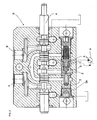
Figure 2 shows a sectional view of an element of the load sensing, flow sharing directional control valve as shown inFigure 1 , -
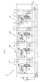
Figure 3 shows the hydraulic circuit of a directional control valve with one element not participating in flow-rate reduction, according to the present invention, -
Figure 4 shows a sectional view of the elements of the directional control valve as shown infigure 3 which participate in flow-rate reduction under saturation conditions, -
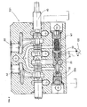
Figure 5 shows a sectional view of the element of the directional control valve as shown infigure 3 which does not participate in flow-rate reduction under saturation conditions. - Referring to
Figures 2 and1 , there are shown by way of example, a sectional view of an element E of a load sensing flow sharing directional control valve and the hydraulic circuit of a directional control valve composed of three of such elements E1, E2, E3 respectively, according to a classical configuration, as used by the applicant hereof and as disclosed and claimed in patentsEP1628018 andUS 7,182,097 . - In this kind of directional control valve V, under multiple simultaneous actuation conditions, in the element that is at the higher pressure the
compensator 3 and thepiston 5 move all the way to the right while remaining in contact with each other. - As a whole, these two contacting components operate as a check valve and the
piston 5, by mechanically pushing the ball S, causes pressure between thespool 4 and the pressure compensator 3 (pressure in point 2) to be supplied to the LS signal channel C ; through channel C, the pressure inpoint 2, which is the higher, is transmitted to the pump P and to the other elements and moves apart thepressure compensator 3 and thepiston 5 of the elements at lower pressure. - The
piston 5 of the elements at lower pressure abuts on one side;thepressure compensator 3, being subjected to the LS pressure through channel C on one side and to the pressure between thespool 4 and the pressure compensator 3 (pressure in point 2) on theother side 3a, acts as a pressure compensator, thereby imparting to thepoint 2 of the element at lower pressure the same pressure as at thepoint 2 of the element that is at higher pressure. - Due to the above, all the elements E1, E2, E3 have the same pressure at
point 2, downstream from thespool 4. - Furthermore, given the presence of a single channel, the elements E1, E2, E3 have the same pressure as the pump P upstream from the
spool 4; as a result all thespools 4 are subjected to the same pressure differential, i.e. the one imposed by thepressure compensator 3 on the pump P. - The flow-rate through the
spool 4 is the one required for generating the above pressure differential. - It shall be noted that the flow-rate delivered by the pump P is the one required for such differential to be maintained constant.
- If the global flow-rate required by the various elements E1, E2, E3 exceeds the maximum pump P flow-rate (saturation condition), the pump is not able to provide a constant pressure differential, thereby causing a pressure drop.
- Since the pressure differential is identical across all the
spools 4, as explained above, under saturation conditions this differential decreases of the same amount across all the elements and also the flow-rate has a proportional decreases across all the elements. - This feature is particularly needed in those operating machines, such as excavators, that are required to perform many simultaneous movements, as it affords proper control of the moving machine even under saturation conditions, which occur quite often.
- As mentioned above, amongst the various functions of a machine, one (e.g. turret rotation) might be required to maintain the same speed as before saturation, or anyway to be slowed down much less than the other functions: the prior art solution consists in simply providing a separate circuit for such function; while this solution is very simple it still involves high costs and large space requirements.
- Particularly referring to
Figures 3 ,4 and5 , an explanation will be now provided about how the solution of this invention can fulfill the above need and solve the prior art disadvantages - Particularly, in the four-element directional control valve V1 as shown in
Figure 3 , an element E4, which will be referred herein as an element having priority, is modified as described below, whereby it does not participate in flow-rate reduction under saturation conditions, while preserving the feature of maintaining a constant flow-rate to the user irrespective of the variation of the load. - Theother elements E11, E21 and E31 operate under the same principle as shown in
Figures 1 and2 and as further described with the help ofFigure 4 . - These elements include a
proportional control spool 40 and, within the same lapped bore, alocal compensator 30 that solves the function of pressure compensator and apiston 50, with a spring M1 of negligible force acting thereon; thepiston 50 in turn mechanically operates on the pressure signal selector S1 by keeping it open or closed depending on the pressures on users. - The spring side M1 of the
piston 50 is acted upon by the pressure of the user of its element, as taken between thelocal compensator 30 and the user itself, theside 30a of thelocal compensator 30 is acted upon by the pressure taken atpoint 20, i.e. between thespool 40 and thecompensator 30, and the load sensing signal operates between thepiston 50 and thelocal compensator 30. - In the element that is at the higher pressure, the
piston 50 presses against the selector S1 of thelocal compensator 30 and the assembly of thecompensator 30 in contact with thepiston 50 operate as a one-way valve. - The selector S1 is kept open by the mechanical action of the
piston 50 and connects the pressure signal ofpoint 20, between thespool 40 and thelocal compensator 30, to the load sensing signal channel C1 ; such signal reaches thepump 100 compensator or alternatively the inlet cover compensator, and arrives between thelocal compensator 30 and thepiston 50 of the elements at lower pressure. - Therefore, in the elements at lower pressure, the
piston 50 and thecompensator 30 are moved apart from each other; thus, the selector S1 closes and thelocal compensator 30 fulfills its pressure compensation function. - Referring to
Figure 5 , the construction architecture of the element having priority E4 will be now described. - The element E4 is similar in construction to the above elements E11, E21, E31; the changes to be made to obtain the desired function include:
- replacement of the
components spring 14, alocal compensator 9 and a piston / loadsensing signal selector 8; - provision of a
bore 16 in the body of the element E4, for connecting and transmitting the pressure signal received from the pump P between thelocal compensator 9 and the piston / selector 8 (chamber 19). - The
local compensator 9 and the piston /selector 8 are in side-by-side positions within the same lapped bore; thelocal compensator 9 has a through hole therein, which forms thepassage 12 and the piston /selector 8 incorporates a one-way valve 15, which justifies its being referred to as a "piston / selector". - The
spring 14 operates on theside 9a of thelocal compensator 9 and the plug TT closes the lapped bore that contains these components . - It shall be noted also the presence of the following chambers delimited by the various components: a chamber 7 delimited between the plug TT and the piston /
selector 8, achamber 19 delimited between the piston /selector 8 and thelocal compensator 9, a chamber 13 interposed between thelocal compensator 9 and thespring 14. - Within the chamber 7, the piston /
selector 8 is subjected to the pressure of the user; if such pressure rises above the pressure at P (excluding the effect of the spring 14), the piston /selector 8 is pushed against thecompensator 9, which is in turn pushed to close the passage between P and the user, thus operating as a one-way valve . - The
local compensator 9 is located downstream from the metering recess N of thespool 10 and, within thechamber 19, is no longer subjected to the LS signal pressure but to the pressure of thepump 100; on the opposite side, i.e. within the chamber 13, it is subjected not only to the pressure between thespool 10 and the compensator 9 (pressure at point 11) but also to thespring force 14, which is designed in such a manner as to generate, through the metering recesses N of thespool 10, a pressure differential suitably lower than the general pressure of the present directional control valve V1. - The above element E4 does not participate in flow-rate reduction under saturation conditions although it preserves the feature of maintaining a constant flow-rate to the user irrespective of the variation of the load; the latter feature will more clearly explained with reference to the following numerical example.
- Considering the actuation of the element having priority E4: during the initial transient the pressure of the user, taken from the pipe 6 and higher than the pressure at P, reaches the chamber 7 on the side of the piston /
selector 8 and pushes the latter against thecompensator 9 thereby closing, as mentioned above, the passage between P and the user; the assembly of thecompensator 9 and the piston /selector 8 thus operates as a one-way valve. - In the meantime, the pressure at P, which still corresponds to the stand-by value of the pump 100 (or of the inlet cover compensator) arrives , through the
bore 16, between thecompensator 9 and the piston /selector 8. - Once the
compensator 9 has closed the passage between P and the user , the pressure at P propagates, through the actuatedspool 10, to thechamber 11 and reaches, through thepassage 12 within thecompensator 9, the chamber 13 with thespring 14 therein. - Through the one-
way valve 15 in the piston /selector 8, the pressure in the chamber 6 is transferred to the channel C1 and from the latter to thepump 100 compensator (or the inlet cover compensator) and further comes between thecompensator 30 and thepiston 50 of the other elements E11, E21, E31. - In response to the Load sensing signal pressure in C1, the pump 100 (or the inlet cover compensator) generates a pressure at P which is equal to that in the channel C1, increased by the differential pressure set by the compensator of the
pump 100. - In this numeric example, the differential pressure set by the compensator of the
pump 100 is assumed to be 14 bar and the action of thespring 14 is assumed to be 5 bar. - With such pressure at P which, due to the above assumptions, is higher than pressure in C1 by 14 bar, the
piston 8 abuts against the plug TT. - Therefore, on the side of
chamber 19, the compensator is subjected to the pressure at P, and on the side of chamber 13 it is subjected to the pressure at P increased by the action of thespring 14; it will thus tend to move to the right, thereby opening the passage between thechamber 11 and the user. - As the passage between the
chamber 11 and the user opens, a flow is generated through thespool 10; due to the pressure losses occurring in such flow, the pressure generated in thechamber 11 will be lower than P pressure by the value of such pressure losses. - Considering now the equilibrium of the
compensator 9, this component is subjected to pressure at P on the side ofchamber 19 and to pressure at 11 plus the action of thespring 14, i.e. 5 bar, on the side of chamber 13. - Thus, the
compensator 9 will achieve equilibrium when pressure at 11 will be lower than the pressure at P by 5 bar, i.e. when the flow-rate through thespool 10 will generate a pressure drop of 5 bar. - The overall system will thus achieve equilibrium.
- The
pump 100 senses the load sensing signal pressure and imposes a 14 bar pressure increase at P, whereas thelocal compensator 9, before the signal to thepump 100 is taken at 6, , suppresses 9 of the 14 bar, thereby reducing the actual pressure differential on thespool 10 to 5 bar. - It shall be noted that, assuming identical strokes of the
spool 10, one flow only can generate 5 bar pressure loss regardless of pressures; the feature of constant flow irrespective of the variation of the load typical of load sensing valves is thus ensured. - The other standard elements E11, E21, E31 of the directional control valve V1, will be now assumed to be actuated, all being subjected to a pressure lower than that on the element having priority E4, and under non saturation conditions.
- In these elements, the LS signal in C1 moves the
compensator 30 and thepiston 50 apart, whereas the selector S1 within thecompensators 30 closes the connection betweenpoints 20 and the LS signal channel C1. - According to its known operation, the
compensator 30 will impose onpoint 20 the same pressure as the LS signal existing in C1, thanks to its own equilibrium. - Due to the above these elements have the LS signal pressure at
point 20 and the pressure corresponding to the LS signal pressure increased by the 14 bar differential in P, so the flow through thespools 40 will be the one required to generate a 14 bar pressure drop. - These actuations have no effect on the pressures operating in the element having priority E4 which will continue to operate as described above.
- Assume now that at least one of the elements E11, E21, E32 is subjected to a pressure higher than the pressure of the element having priority E4; as explained above with reference to patent
EP1628018 , this element will generate the LS signal in the channel C1. - Such higher pressure reaches the
piston 8 through the channel C1 and closes the one-way valve 15. - Nevertheless, this higher pressure, as shown in
Figure 5 , does not affect the equilibrium of thecompensator 9 nor the one of thepiston 8 of the element having priority E4. - Therefore, the element having priority E4 is not influenced by the LS pressure generated by another element.
- However, the higher LS signal that reaches the pump 100 (or the inlet cover compensator) generates a higher pressure value at P.
- The increase of pressure at P with respect to that at
point 11, would lead to a pressure drop through thespool 10 of the element having priority E4 and to a consequent flow reduction. - Nevertheless, such pressure increase at P with respect to the pressure at
point 11 and hence at 13, also has an effect in the equilibrium of thecompensator 9, which will tend to close the passage betweenpoint 11 and the user, thereby increasing pressure atpoint 11 itself. - This will occur until a new equilibrium condition is achieved, with the pressure at P being equal to the pressure at
point 11 increased by the 5 bar spring action. - This means that the
compensator 9 maintains a constant 5 bar pressure drop through thespool 10, and hence a constant flow-rate. - Assume now a saturation condition; this means that the
pump 100 can no longer ensure the 14 bar pressure differential, it operates at full capacity and the differential decreases. - Assume also that the pressure differential drops to 10 bar and that the element having priority E4 is the one subjected to a higher pressure.
- If the actuation of the standard elements E11, E21, E32 has led to saturation, the pressure at P is non longer equal to the LS signal pressure plus 14 bar, but is decreased to the LS signal pressure plus 10 bar.
- Now, the reduction of the pressure at P with respect to that at
point 11, would cause a pressure drop through thespool 10 of the element having priority E4 and, as a result, a flow-rate reduction; however, such reduction of the pressure at P with respect to the pressure atpoint 11 and thence at 13 also influences the equilibrium of thecompensator 9, which will tend to open the passage betweenpoint 11 and the user causing a reduction of the pressure atpoint 11 itself. - The
compensator 9 will continue to open the passage betweenpoint 11 and the user (and to reduce the pressure at point 11) until a new equilibrium condition is achieved, i.e. until the pressure atpoint 11 plus the 5 bar action of thespring 14 corresponds again to the pressure at P. - This means that, under saturation conditions, while in the elements E11, E21, E31 the pressure drop through the spool decreases from 14 to 10 bar (thereby causing a proportionally reduced flow-rate across all the elements), in the element having priority E4, the pressure drop is maintained constant at the value of 5 bar , therefore the flow-rate is maintained unchanged.
- In the case the element having priority E4 is one of the elements at lower pressure, the system will behave in the same manner: as pressure decreases at P with respect to the pressure at
point 11, thecompensator 9 opens the passage betweenpoint 11 and the user until a new equilibrium condition is achieved with the same 5 bar pressure drop.
Claims (3)
- A sectional load sensing, flow sharing directional control valve (V1) having two or more sections (E1, ..., E4), characterized in that at least one section (E4) of said control valve (V1)comprises a local compensator (9), having a spring (14) operating on one side thereof (9a), and a selector / piston (8) ; said local compensator (9) and selector / piston (8) being aside and located in the same lapped bore; said local compensator (9) being located downstream from a metering recess (N) of the spool (10), having a bore generating a passage (12) and being subjected to:a. the pressure of the pump (100), instead of a load sensing (LS) signal pressure, in an intermediate chamber (19) opposite another chamber (13) that is acted upon by the spring (14),b. the pressure at point (11), between the spool (10) and the local compensator (9), plus the action of the spring (14), in the chamber (13), the spring (14) being designed for generating, through the mitering recess (N) of the spool (10) a pressure differential suitably lower than the general pressure of the directional control valve (V1)
said selector / piston (8) comprising therein a one-way valve (15) and being subjected to:c. pump pressure coming into the intermediate chamber (19) through a bore (16), on one side,d. the pressure of the user, as taken at pipe (6), on the opposite side, i.e. on the side of a further chamber (7),said section (E4) having the feature of non participating in flow-rate reduction under saturation conditions,i.e. when the global flow-rate required by the various sections (E1,...,E4) of the control valve (V1) exceeds the maximum pump flow-rate, while preserving the feature of maintaining a constant flow-rate to the user, irrespective of the variation of the load. - A directional control valve (V1) as claimed in claim 1, characterized in that if the pressure taken at pipe (6) is higher than pump pressure minus the resistance of the spring (14), the selector / piston (8) is pushed against the local compensator (9) which is in turn pushed to close the passage between the pump and the user by operating as a one-way valve.
- A directional control valve (V1) as claimed in claim 1, characterized in that the local compensator (9) of the section having priority (E4) maintains a constant pressure drop through the spool (10) thereby maintaining a constant flow-rate, the local compensator (9) being subjected on one side to the pump pressure at (P) and on the other side to the pressure at point (11) increased by the action of the spring (14), and achieving equilibrium when pressure at point (11) is lower than pressure at (P) minus the value of the spring (14), i.e. when the flow-rate through the spool (10) will generate a constant pressure drop which is equal to the constant value of the spring (14).
Applications Claiming Priority (1)
| Application Number | Priority Date | Filing Date | Title |
|---|---|---|---|
| PCT/IT2007/000449 WO2009001377A1 (en) | 2007-06-26 | 2007-06-26 | Load sensing directional control valve with an element having priority under saturation conditions |
Publications (2)
| Publication Number | Publication Date |
|---|---|
| EP2201254A1 EP2201254A1 (en) | 2010-06-30 |
| EP2201254B1 true EP2201254B1 (en) | 2011-08-10 |
Family
ID=39079607
Family Applications (1)
| Application Number | Title | Priority Date | Filing Date |
|---|---|---|---|
| EP20070805661 Active EP2201254B1 (en) | 2007-06-26 | 2007-06-26 | Load sensing directional control valve with an element having priority under saturation conditions |
Country Status (5)
| Country | Link |
|---|---|
| US (1) | US8375975B2 (en) |
| EP (1) | EP2201254B1 (en) |
| KR (1) | KR101431489B1 (en) |
| AT (1) | ATE519949T1 (en) |
| WO (1) | WO2009001377A1 (en) |
Families Citing this family (8)
| Publication number | Priority date | Publication date | Assignee | Title |
|---|---|---|---|---|
| IT1395462B1 (en) * | 2009-09-03 | 2012-09-21 | Brevini Fluid Power S P A | DISTRIBUTION VALVE |
| WO2011096001A1 (en) | 2010-02-02 | 2011-08-11 | Bucher Hydraulics S.P.A. | Hydraulic section for load sensing applications and multiple hydraulic distributor |
| DE102012014359A1 (en) | 2012-07-19 | 2014-01-23 | Hydac Filtertechnik Gmbh | Hydraulic valve apparatus i.e. flow divider valve, has first control device controlled by pilot valve pressures, second control device designed as compensator, and third control device designed as switching unit for first control device |
| CN103267147B (en) * | 2013-05-28 | 2015-02-11 | 卢宇 | Small-flow high-pressure load sensitive proportional multi-way valve |
| JP6656913B2 (en) * | 2015-12-24 | 2020-03-04 | 株式会社クボタ | Working machine hydraulic system |
| CN108708882B (en) * | 2018-06-08 | 2020-03-31 | 吴万敏 | Multi-way valve for agricultural machinery |
| KR102498279B1 (en) | 2020-12-18 | 2023-02-09 | 충남대학교산학협력단 | Traction control hydraulic system for agricultural tractor and traction control method for agricultural tractor |
| IT202100009830A1 (en) * | 2021-04-19 | 2022-10-19 | Walvoil Spa | HYDRAULIC DISTRIBUTOR WITH COMPENSATING DEVICE FOR DIRECTIONAL VALVES |
Family Cites Families (11)
| Publication number | Priority date | Publication date | Assignee | Title |
|---|---|---|---|---|
| US3703186A (en) * | 1971-08-12 | 1972-11-21 | Gen Motors Corp | Flow divider control valve assembly |
| US3937129A (en) * | 1974-10-23 | 1976-02-10 | The Scott & Fetzer Company | Load responsive system with area change flow extender |
| US4206689A (en) * | 1977-08-22 | 1980-06-10 | Caterpillar Tractor Co. | Priority system |
| US4488569A (en) * | 1982-04-23 | 1984-12-18 | Trw Inc. | Apparatus with staged pressure differential for controlling fluid flow |
| US5487403A (en) * | 1987-01-29 | 1996-01-30 | Mollo; James R. | Variable discharge pump with low unload to secondary |
| DE4005967C2 (en) * | 1990-02-26 | 1996-05-09 | Rexroth Mannesmann Gmbh | Control arrangement for several hydraulic consumers |
| DE4237932C2 (en) * | 1992-11-10 | 1997-12-11 | Hydraulik Ring Gmbh | Volume flow control for automotive hydraulics, in particular for steering devices of motor vehicles |
| US6782697B2 (en) * | 2001-12-28 | 2004-08-31 | Caterpillar Inc. | Pressure-compensating valve with load check |
| US6895852B2 (en) * | 2003-05-02 | 2005-05-24 | Husco International, Inc. | Apparatus and method for providing reduced hydraulic flow to a plurality of actuatable devices in a pressure compensated hydraulic system |
| US7182097B2 (en) * | 2004-08-17 | 2007-02-27 | Walvoil S.P.A. | Anti-saturation directional control valve composed of two or more sections with pressure selector compensators |
| ITPR20060036A1 (en) | 2006-04-12 | 2007-10-13 | Walvoil Spa | PRESSURE COMPENSATOR WITH DIFFERENTIAL AREAS PILOTED AND ITS PILOT SYSTEM. |
-
2007
- 2007-06-26 US US12/666,754 patent/US8375975B2/en active Active
- 2007-06-26 WO PCT/IT2007/000449 patent/WO2009001377A1/en not_active Ceased
- 2007-06-26 AT AT07805661T patent/ATE519949T1/en not_active IP Right Cessation
- 2007-06-26 EP EP20070805661 patent/EP2201254B1/en active Active
- 2007-06-26 KR KR1020107001321A patent/KR101431489B1/en not_active Expired - Fee Related
Also Published As
| Publication number | Publication date |
|---|---|
| EP2201254A1 (en) | 2010-06-30 |
| KR101431489B1 (en) | 2014-08-20 |
| ATE519949T1 (en) | 2011-08-15 |
| US20100176324A1 (en) | 2010-07-15 |
| US8375975B2 (en) | 2013-02-19 |
| KR20100023038A (en) | 2010-03-03 |
| WO2009001377A1 (en) | 2008-12-31 |
Similar Documents
| Publication | Publication Date | Title |
|---|---|---|
| US8375975B2 (en) | Load sensing directional control valve with an element having priority under saturation conditions | |
| EP0911529B1 (en) | Hydraulic control valve system with non-shuttle pressure compensator | |
| US9874884B2 (en) | Valve block having a valve assembly | |
| JP4739529B2 (en) | Control unit for at least two hydraulic consumers and differential pressure valve for the control unit | |
| US5138837A (en) | Load independent valve control for a plurality of hydraulic users | |
| EP2078868A3 (en) | Hydraulic control valve system with isolated pressure compensation | |
| CA2253779A1 (en) | Hydraulic control valve system with split pressure compensator | |
| CA2241248A1 (en) | Pressure compensating hydraulic control valve system | |
| CN109707688B (en) | Flow anti-saturation load sensitive multi-way valve with front pressure compensator | |
| US8430016B2 (en) | Control valve assembly with a workport pressure regulating device | |
| US4275643A (en) | Hydraulic control systems | |
| DE602005002097D1 (en) | Multi-way valve assembly with built-in shuttle valve for pressure gauge provided pressure compensators, with sub-supply avoidance function | |
| US12123502B2 (en) | Inlet section for use in a hydraulic distributor | |
| CN106715924A (en) | Load-sensing valve device | |
| JP2010534816A (en) | Control device and method for controlling at least two hydraulic consumers | |
| JP2007032782A (en) | Hydraulic drive | |
| JP4960646B2 (en) | Load sensing hydraulic controller | |
| KR920703938A (en) | Attachment Flow Switch | |
| USRE29671E (en) | Demand compensated hydraulic system with flow sensitive device | |
| JP2647094B2 (en) | Relief valve | |
| JP3240286B2 (en) | Hydraulic system | |
| JPH01312201A (en) | Hydraulic flow controller | |
| JP3703300B2 (en) | Hydraulic control device | |
| GB2533034A (en) | Systems and methods for flow summation in a hydraulic system with open center control valves | |
| JP2007270982A (en) | Hydraulic control device for construction machine |
Legal Events
| Date | Code | Title | Description |
|---|---|---|---|
| PUAI | Public reference made under article 153(3) epc to a published international application that has entered the european phase |
Free format text: ORIGINAL CODE: 0009012 |
|
| 17P | Request for examination filed |
Effective date: 20100208 |
|
| AK | Designated contracting states |
Kind code of ref document: A1 Designated state(s): AT BE BG CH CY CZ DE DK EE ES FI FR GB GR HU IE IS IT LI LT LU LV MC MT NL PL PT RO SE SI SK TR |
|
| AX | Request for extension of the european patent |
Extension state: AL BA HR MK RS |
|
| DAX | Request for extension of the european patent (deleted) | ||
| GRAP | Despatch of communication of intention to grant a patent |
Free format text: ORIGINAL CODE: EPIDOSNIGR1 |
|
| GRAS | Grant fee paid |
Free format text: ORIGINAL CODE: EPIDOSNIGR3 |
|
| GRAA | (expected) grant |
Free format text: ORIGINAL CODE: 0009210 |
|
| AK | Designated contracting states |
Kind code of ref document: B1 Designated state(s): AT BE BG CH CY CZ DE DK EE ES FI FR GB GR HU IE IS IT LI LT LU LV MC MT NL PL PT RO SE SI SK TR |
|
| REG | Reference to a national code |
Ref country code: GB Ref legal event code: FG4D |
|
| REG | Reference to a national code |
Ref country code: CH Ref legal event code: EP |
|
| REG | Reference to a national code |
Ref country code: IE Ref legal event code: FG4D |
|
| REG | Reference to a national code |
Ref country code: DE Ref legal event code: R096 Ref document number: 602007016475 Country of ref document: DE Effective date: 20111013 |
|
| REG | Reference to a national code |
Ref country code: NL Ref legal event code: VDEP Effective date: 20110810 |
|
| LTIE | Lt: invalidation of european patent or patent extension |
Effective date: 20110810 |
|
| PG25 | Lapsed in a contracting state [announced via postgrant information from national office to epo] |
Ref country code: FI Free format text: LAPSE BECAUSE OF FAILURE TO SUBMIT A TRANSLATION OF THE DESCRIPTION OR TO PAY THE FEE WITHIN THE PRESCRIBED TIME-LIMIT Effective date: 20110810 Ref country code: IS Free format text: LAPSE BECAUSE OF FAILURE TO SUBMIT A TRANSLATION OF THE DESCRIPTION OR TO PAY THE FEE WITHIN THE PRESCRIBED TIME-LIMIT Effective date: 20111210 Ref country code: NL Free format text: LAPSE BECAUSE OF FAILURE TO SUBMIT A TRANSLATION OF THE DESCRIPTION OR TO PAY THE FEE WITHIN THE PRESCRIBED TIME-LIMIT Effective date: 20110810 Ref country code: LT Free format text: LAPSE BECAUSE OF FAILURE TO SUBMIT A TRANSLATION OF THE DESCRIPTION OR TO PAY THE FEE WITHIN THE PRESCRIBED TIME-LIMIT Effective date: 20110810 Ref country code: SE Free format text: LAPSE BECAUSE OF FAILURE TO SUBMIT A TRANSLATION OF THE DESCRIPTION OR TO PAY THE FEE WITHIN THE PRESCRIBED TIME-LIMIT Effective date: 20110810 Ref country code: PT Free format text: LAPSE BECAUSE OF FAILURE TO SUBMIT A TRANSLATION OF THE DESCRIPTION OR TO PAY THE FEE WITHIN THE PRESCRIBED TIME-LIMIT Effective date: 20111212 |
|
| REG | Reference to a national code |
Ref country code: AT Ref legal event code: MK05 Ref document number: 519949 Country of ref document: AT Kind code of ref document: T Effective date: 20110810 |
|
| PG25 | Lapsed in a contracting state [announced via postgrant information from national office to epo] |
Ref country code: GR Free format text: LAPSE BECAUSE OF FAILURE TO SUBMIT A TRANSLATION OF THE DESCRIPTION OR TO PAY THE FEE WITHIN THE PRESCRIBED TIME-LIMIT Effective date: 20111111 Ref country code: LV Free format text: LAPSE BECAUSE OF FAILURE TO SUBMIT A TRANSLATION OF THE DESCRIPTION OR TO PAY THE FEE WITHIN THE PRESCRIBED TIME-LIMIT Effective date: 20110810 Ref country code: SI Free format text: LAPSE BECAUSE OF FAILURE TO SUBMIT A TRANSLATION OF THE DESCRIPTION OR TO PAY THE FEE WITHIN THE PRESCRIBED TIME-LIMIT Effective date: 20110810 Ref country code: AT Free format text: LAPSE BECAUSE OF FAILURE TO SUBMIT A TRANSLATION OF THE DESCRIPTION OR TO PAY THE FEE WITHIN THE PRESCRIBED TIME-LIMIT Effective date: 20110810 Ref country code: PL Free format text: LAPSE BECAUSE OF FAILURE TO SUBMIT A TRANSLATION OF THE DESCRIPTION OR TO PAY THE FEE WITHIN THE PRESCRIBED TIME-LIMIT Effective date: 20110810 Ref country code: CY Free format text: LAPSE BECAUSE OF FAILURE TO SUBMIT A TRANSLATION OF THE DESCRIPTION OR TO PAY THE FEE WITHIN THE PRESCRIBED TIME-LIMIT Effective date: 20110810 |
|
| PG25 | Lapsed in a contracting state [announced via postgrant information from national office to epo] |
Ref country code: BE Free format text: LAPSE BECAUSE OF FAILURE TO SUBMIT A TRANSLATION OF THE DESCRIPTION OR TO PAY THE FEE WITHIN THE PRESCRIBED TIME-LIMIT Effective date: 20110810 |
|
| PG25 | Lapsed in a contracting state [announced via postgrant information from national office to epo] |
Ref country code: CZ Free format text: LAPSE BECAUSE OF FAILURE TO SUBMIT A TRANSLATION OF THE DESCRIPTION OR TO PAY THE FEE WITHIN THE PRESCRIBED TIME-LIMIT Effective date: 20110810 Ref country code: SK Free format text: LAPSE BECAUSE OF FAILURE TO SUBMIT A TRANSLATION OF THE DESCRIPTION OR TO PAY THE FEE WITHIN THE PRESCRIBED TIME-LIMIT Effective date: 20110810 |
|
| PG25 | Lapsed in a contracting state [announced via postgrant information from national office to epo] |
Ref country code: RO Free format text: LAPSE BECAUSE OF FAILURE TO SUBMIT A TRANSLATION OF THE DESCRIPTION OR TO PAY THE FEE WITHIN THE PRESCRIBED TIME-LIMIT Effective date: 20110810 Ref country code: EE Free format text: LAPSE BECAUSE OF FAILURE TO SUBMIT A TRANSLATION OF THE DESCRIPTION OR TO PAY THE FEE WITHIN THE PRESCRIBED TIME-LIMIT Effective date: 20110810 |
|
| PLBE | No opposition filed within time limit |
Free format text: ORIGINAL CODE: 0009261 |
|
| STAA | Information on the status of an ep patent application or granted ep patent |
Free format text: STATUS: NO OPPOSITION FILED WITHIN TIME LIMIT |
|
| PG25 | Lapsed in a contracting state [announced via postgrant information from national office to epo] |
Ref country code: DK Free format text: LAPSE BECAUSE OF FAILURE TO SUBMIT A TRANSLATION OF THE DESCRIPTION OR TO PAY THE FEE WITHIN THE PRESCRIBED TIME-LIMIT Effective date: 20110810 |
|
| 26N | No opposition filed |
Effective date: 20120511 |
|
| REG | Reference to a national code |
Ref country code: DE Ref legal event code: R097 Ref document number: 602007016475 Country of ref document: DE Effective date: 20120511 |
|
| PG25 | Lapsed in a contracting state [announced via postgrant information from national office to epo] |
Ref country code: MC Free format text: LAPSE BECAUSE OF NON-PAYMENT OF DUE FEES Effective date: 20120630 |
|
| REG | Reference to a national code |
Ref country code: CH Ref legal event code: PL |
|
| REG | Reference to a national code |
Ref country code: CH Ref legal event code: PL |
|
| GBPC | Gb: european patent ceased through non-payment of renewal fee |
Effective date: 20120626 |
|
| REG | Reference to a national code |
Ref country code: IE Ref legal event code: MM4A |
|
| PG25 | Lapsed in a contracting state [announced via postgrant information from national office to epo] |
Ref country code: LI Free format text: LAPSE BECAUSE OF NON-PAYMENT OF DUE FEES Effective date: 20120630 Ref country code: IE Free format text: LAPSE BECAUSE OF NON-PAYMENT OF DUE FEES Effective date: 20120626 Ref country code: ES Free format text: LAPSE BECAUSE OF FAILURE TO SUBMIT A TRANSLATION OF THE DESCRIPTION OR TO PAY THE FEE WITHIN THE PRESCRIBED TIME-LIMIT Effective date: 20111121 Ref country code: GB Free format text: LAPSE BECAUSE OF NON-PAYMENT OF DUE FEES Effective date: 20120626 Ref country code: CH Free format text: LAPSE BECAUSE OF NON-PAYMENT OF DUE FEES Effective date: 20120630 |
|
| PG25 | Lapsed in a contracting state [announced via postgrant information from national office to epo] |
Ref country code: BG Free format text: LAPSE BECAUSE OF FAILURE TO SUBMIT A TRANSLATION OF THE DESCRIPTION OR TO PAY THE FEE WITHIN THE PRESCRIBED TIME-LIMIT Effective date: 20111110 |
|
| PG25 | Lapsed in a contracting state [announced via postgrant information from national office to epo] |
Ref country code: MT Free format text: LAPSE BECAUSE OF FAILURE TO SUBMIT A TRANSLATION OF THE DESCRIPTION OR TO PAY THE FEE WITHIN THE PRESCRIBED TIME-LIMIT Effective date: 20110810 |
|
| PG25 | Lapsed in a contracting state [announced via postgrant information from national office to epo] |
Ref country code: LU Free format text: LAPSE BECAUSE OF NON-PAYMENT OF DUE FEES Effective date: 20120626 |
|
| PG25 | Lapsed in a contracting state [announced via postgrant information from national office to epo] |
Ref country code: HU Free format text: LAPSE BECAUSE OF FAILURE TO SUBMIT A TRANSLATION OF THE DESCRIPTION OR TO PAY THE FEE WITHIN THE PRESCRIBED TIME-LIMIT Effective date: 20070626 |
|
| REG | Reference to a national code |
Ref country code: FR Ref legal event code: PLFP Year of fee payment: 10 |
|
| REG | Reference to a national code |
Ref country code: FR Ref legal event code: PLFP Year of fee payment: 11 |
|
| REG | Reference to a national code |
Ref country code: FR Ref legal event code: PLFP Year of fee payment: 12 |
|
| PGFP | Annual fee paid to national office [announced via postgrant information from national office to epo] |
Ref country code: FR Payment date: 20230620 Year of fee payment: 17 Ref country code: DE Payment date: 20230620 Year of fee payment: 17 |
|
| P01 | Opt-out of the competence of the unified patent court (upc) registered |
Effective date: 20230622 |
|
| PGFP | Annual fee paid to national office [announced via postgrant information from national office to epo] |
Ref country code: TR Payment date: 20230620 Year of fee payment: 17 |
|
| PGFP | Annual fee paid to national office [announced via postgrant information from national office to epo] |
Ref country code: IT Payment date: 20230630 Year of fee payment: 17 |
|
| REG | Reference to a national code |
Ref country code: DE Ref legal event code: R119 Ref document number: 602007016475 Country of ref document: DE |
|
| PG25 | Lapsed in a contracting state [announced via postgrant information from national office to epo] |
Ref country code: DE Free format text: LAPSE BECAUSE OF NON-PAYMENT OF DUE FEES Effective date: 20250101 |
|
| PG25 | Lapsed in a contracting state [announced via postgrant information from national office to epo] |
Ref country code: FR Free format text: LAPSE BECAUSE OF NON-PAYMENT OF DUE FEES Effective date: 20240630 |
|
| PG25 | Lapsed in a contracting state [announced via postgrant information from national office to epo] |
Ref country code: IT Free format text: LAPSE BECAUSE OF NON-PAYMENT OF DUE FEES Effective date: 20240626 |