EP1628018A1 - Anti-saturation directional control valve composed of two or more sections with pressure selector compensators - Google Patents
Anti-saturation directional control valve composed of two or more sections with pressure selector compensators Download PDFInfo
- Publication number
- EP1628018A1 EP1628018A1 EP20050013972 EP05013972A EP1628018A1 EP 1628018 A1 EP1628018 A1 EP 1628018A1 EP 20050013972 EP20050013972 EP 20050013972 EP 05013972 A EP05013972 A EP 05013972A EP 1628018 A1 EP1628018 A1 EP 1628018A1
- Authority
- EP
- European Patent Office
- Prior art keywords
- pressure
- compensator
- pressure compensator
- piston
- directional control
- Prior art date
- Legal status (The legal status is an assumption and is not a legal conclusion. Google has not performed a legal analysis and makes no representation as to the accuracy of the status listed.)
- Granted
Links
Images

Classifications
-
- F—MECHANICAL ENGINEERING; LIGHTING; HEATING; WEAPONS; BLASTING
- F15—FLUID-PRESSURE ACTUATORS; HYDRAULICS OR PNEUMATICS IN GENERAL
- F15B—SYSTEMS ACTING BY MEANS OF FLUIDS IN GENERAL; FLUID-PRESSURE ACTUATORS, e.g. SERVOMOTORS; DETAILS OF FLUID-PRESSURE SYSTEMS, NOT OTHERWISE PROVIDED FOR
- F15B13/00—Details of servomotor systems ; Valves for servomotor systems
- F15B13/01—Locking-valves or other detent i.e. load-holding devices
-
- F—MECHANICAL ENGINEERING; LIGHTING; HEATING; WEAPONS; BLASTING
- F15—FLUID-PRESSURE ACTUATORS; HYDRAULICS OR PNEUMATICS IN GENERAL
- F15B—SYSTEMS ACTING BY MEANS OF FLUIDS IN GENERAL; FLUID-PRESSURE ACTUATORS, e.g. SERVOMOTORS; DETAILS OF FLUID-PRESSURE SYSTEMS, NOT OTHERWISE PROVIDED FOR
- F15B13/00—Details of servomotor systems ; Valves for servomotor systems
- F15B13/02—Fluid distribution or supply devices characterised by their adaptation to the control of servomotors
- F15B13/04—Fluid distribution or supply devices characterised by their adaptation to the control of servomotors for use with a single servomotor
- F15B13/0416—Fluid distribution or supply devices characterised by their adaptation to the control of servomotors for use with a single servomotor with means or adapted for load sensing
- F15B13/0417—Load sensing elements; Internal fluid connections therefor; Anti-saturation or pressure-compensation valves
- F15B13/0418—Load sensing elements sliding within a hollow main valve spool
-
- Y—GENERAL TAGGING OF NEW TECHNOLOGICAL DEVELOPMENTS; GENERAL TAGGING OF CROSS-SECTIONAL TECHNOLOGIES SPANNING OVER SEVERAL SECTIONS OF THE IPC; TECHNICAL SUBJECTS COVERED BY FORMER USPC CROSS-REFERENCE ART COLLECTIONS [XRACs] AND DIGESTS
- Y10—TECHNICAL SUBJECTS COVERED BY FORMER USPC
- Y10T—TECHNICAL SUBJECTS COVERED BY FORMER US CLASSIFICATION
- Y10T137/00—Fluid handling
- Y10T137/8593—Systems
- Y10T137/86493—Multi-way valve unit
- Y10T137/86718—Dividing into parallel flow paths with recombining
- Y10T137/86759—Reciprocating
- Y10T137/86791—Piston
- Y10T137/86799—With internal flow passage
- Y10T137/86807—Sequential opening or closing of serial ports in single flow line
-
- Y—GENERAL TAGGING OF NEW TECHNOLOGICAL DEVELOPMENTS; GENERAL TAGGING OF CROSS-SECTIONAL TECHNOLOGIES SPANNING OVER SEVERAL SECTIONS OF THE IPC; TECHNICAL SUBJECTS COVERED BY FORMER USPC CROSS-REFERENCE ART COLLECTIONS [XRACs] AND DIGESTS
- Y10—TECHNICAL SUBJECTS COVERED BY FORMER USPC
- Y10T—TECHNICAL SUBJECTS COVERED BY FORMER US CLASSIFICATION
- Y10T137/00—Fluid handling
- Y10T137/8593—Systems
- Y10T137/87169—Supply and exhaust
Landscapes
- Engineering & Computer Science (AREA)
- Physics & Mathematics (AREA)
- Fluid Mechanics (AREA)
- Mechanical Engineering (AREA)
- General Engineering & Computer Science (AREA)
- Fluid-Pressure Circuits (AREA)
Abstract
Description
- The present invention refers to an anti-saturation directional control valve composed of two or more sections with pressure selector compensator.
- Function of directional control valves is opening, closing or sheering the oil flow by means of control signals that can be of the manual, pneumatic, hydraulic or electric types.
- In general, they are composed of a hollow body in which a moving element slides, called drawer or spool, that, depending on its assumed position, connects the different circuit lines respectively to fluid delivery or return.
- The directional control valve spool can accurately assume its positions, immediately providing as output the full flow-rate or completely shutting the flow off; in this case, these are directional control valves with "on-off" output.
- On the contrary, if the spool can assume, in addition to its end positions, infinite intermediate positions (metering positions) so as to be able to obtain variable flows, these are proportional directional control valves.
- In this case, the sliding element or spool also automatically performs the function of non-compensated flow-rate control valve. In a non-compensated flow-rate control valve, the flow-rate is affected by input and output pressure variations.
- In order for the abovementioned variation not to affect the flow-rates, it is necessary to use another component, called pressure compensator, which keeps the pressure drop ΔP constant through the spool and therefore keeps the flow-rate on the directional control valve ports unchanged.
- Inserting a pressure compensator therefore makes the flow-rate univocally linked to the spool stroke and independent from the load.
- Since the section workports are two, the section itself with its related spool is designed so that the only pressure compensator intervenes indifferently on both workports.
- When mobile machines are dealt with, the use of many sections in a single block called directional control valve is widely spread.
- Globally, there is a number of sections equal to the number of actuators to be served.
- The operator, acting on the control lever, gradually moves the directional control valve spool and controls the spool orifices.
- In case the simultaneous use of many actuators requires a global flow-rate that is higher than the maximum pump flow-rate, the system comes to "saturation".
- In order to solve such inconvenience, a suitable choice and arrangement of the pressure compensators are necessary so that the flow-rate reduction on the working ports, with respect to the one defined by the spool strokes, is percentually shared among all working ports.
- Such solution, called anti-saturation, allows, keeping if not the desired speeds, the relative movement between the actuators similar.
- Directional control valves arrangements that solve the majority of the abovementioned problems are already known in the art.
- A first prior art example is shown in US 4,719,753 in which one pressure compensator is provided for every workport instead of one for every section, this resulting in the use of twice the number of pressure compensators for the same number of workports.
- Moreover, as can be read from the patent, the signal sent from the workport with higher pressure to all pressure compensators and to the pump pressure compensator is the one of the workport downstream of the pressure compensator with higher pressure. In order to avoid the load dip, this is not directly sent but copied (by means of a four-way two-position spool, that is not on-off but able to assume intermediate positions continuously) taking off oil upstream of the pressure compensator (between spool and pressure compensator).
- It must be remembered that the pressure drop effective to determin the flow-rate through the spool is given by the stand-by imposed by the pump less the fixed pressure losses between the pump and the signal taking off point. Being this latter one taken off downstream of the pressure compensator, also its losses are negatively affecting the effective pressure drop. At maximum flow-rates, it is easy to have 1-2 bars of pressure losses that on a stand-by that can range from 10 to 20 bars can be equal to 10-20%. Moreover, the workport pressure taken off downstream of the pressure compensator on the section with higher pressure is imposed, by means of the pressure compensator in the section with lower pressure, upstream of the pressure compensator (between spool and pressure compensator). Therefore, in the section with lower pressure, the effective pressure drop is greater than in the section with higher pressure. It follows thereby that a reversal of the section with higher pressure generates an increase of the effective pressure drop over the one previously with higher pressure and vice versa, to which a step flow-rate increase corresponds and vice versa.
- Another example is shown in US 5,715,865: therein, the pressure signal is taken off upstream of the pressure compensator. Higher pressure value is sent, through a series of shuttle valves, to the pump and to all local pressure compensators including, however, also the one on the section with higher pressure.
- It results that this latter one has the same pressure on both sides: should a spring be inserted in the classical check valve position (i.e. in the orifice closing direction through the pressure compensator itself) the pressure compensator would close the orifice; for this reason it is exactly placed in the opposite direction. Being built in this way, however, the pressure compensator does not work as check valve any more (due to the fact that it is normally open) from which the need arises of inserting a check valve apart inside the pressure compensator to avoid load dipping.
- Moreover, as prior art example, US 5,890,362 is mentioned, wherein the particular shape of the pressure compensator must be immediately taken into account, that here is divided in two in order to operate both as selector and as check valve.
- In particular, the arrangement of pressures must be observed, that operate on the set of the two components of the pressure compensator disclosed in US 5,890,362: at one end the pressure upstream of the pressure compensator is sent and at the other end the load sensing signal pressure is sent, that is taken off through the supply passage obtained in the body of the directional control valve and the bridge passage pressure (load pressure) arrives between the two components.
- On the contrary, in the present invention, at one end of the pressure compensator the pressure upstream of the pressure compensator acts, while the workport pressure acts at the other end, while in the middle there is the load sensing signal, now taken off inside the pressure compensator itself.
- Moreover, still in US 5,890,362, the second part of the pressure compensator (valve element) operates as 2-way and 2-position valve for selecting the signal while the first part (poppet) performs the function of a check valve only after this first part has been detached from the second.
- On the contrary, in the present invention, the second part is only a piston inserted in the same bore that, in the section with higher pressure, is always joined to the first part and, having at its ends the pressure upstream and downstream of the pressure compensator itself, operates as a check valve.
- Moreover, always in the section with higher pressure, the piston, being kept joined to the first part, keeps the selector mechanically open allowing the pressure taken off upstream of the pressure compensator (not the one downstream of the pressure compensator with the already-described advantages) to arrive between the two parts and from here to the pressure compensators of the sections with lower pressure through a suitable passage.
- In these latter ones, said signal detaches the piston from the first part that, having the signal pressure on one side and the pressure upstream of the pressure compensator on the other side, performs in all respects the function of pressure compensator (not of check valve as in the mentioned patent).
- Moreover, the piston, by moving away, automatically closes the passage of the signal inside the pressure compensator itself.
- Contrary to what has been said above, in US 5,890,362, the pressure compensators of the sections with lower pressure perform the actual function of pressure compensator only if the parts are joined.
- For the same reason, the arrangement of the spring in the pressure compensator is different, namely in US 5,890,362 it can be found between the pressure compensator parts, moving the parts away, while in the present invention, it is arranged on one side like in a check valve.
- Describing the technique adopted in US 5,806,312, it must be observed the use of the pressure compensator as a selector, from which it stems that only in the section with higher pressure the pressure compensator is so lifted to open the internal hole towards the spring side of the pressure compensator itself, thereby taking the pressure upstream of the pressure compensator to the other pressure compensators and to the pump. On the contrary, the sections with lower pressure are less lifted, never getting to open such hole.
- Since the pressure compensator, due to its function, has to open the passage between pump and workport before opening the signal hole, it is not able to prevent, in those transients where the workport pressure exceeds the pump pressure, the load from dipping.
- It is therefore necessary to insert, downstream of the pressure compensator, check valves adapted to prevent such phenomenon.
- The same Applicant has built a mono-block anti-saturation directional control valve for front loaders: excluding the specific application, the anti-saturation concept remains valid, that however is inserted in a mono-block directional control device, specifically for two hydraulic cylinders.
- Object of the present invention is obtaining an anti-saturation directional control valve composed of two or more sections with pressure selector compensator that allows compensating the pressures on the workports and prevents system saturation when the simultaneous use of many actuators requires a global flow-rate that is greater than the maximum pump flow-rate.
- Among the advantages that can be obtained from the present invention, in addition to having an object composed with a number of sections that is equal to the number of actuators to be fed that contain the same hydraulic layout, the following must be pointed out:
- Absence of load dipping transients due to the fact that the oil actuating the pump pressure compensator is taken off upstream of the pressure compensator: since this operates as check valve, it is therefore not taken off from the workport;
- Increase of effective pressure drop on the spool, which means a higher flow-rate with the same stand-by, namely a lower stand-by with the same flow-rate, namely lower energy losses. This because the stand-by imposed by the pump is between pump and workport downstream of the spool upstream of the pressure compensator;
- Absence of effective pressure drop steps and consequent flow-rate steps upon reversal of the workport with higher pressure due to the fact that the effective pressure drop is the same for all spools, both the one with higher pressure and those with lower pressure;
- Suppression of the need to insert check valves in the circuit to avoid load dipping phenomena: this function is performed by the pressure compensator during particular operating times;
- Reduction of hydraulic circuit complexity and above all reduction of tool machining to be carried out on each component due to the fact that the logic selector element is embedded in the pressure compensator itself, with consequent costs reduction.
- These objectives and advantages are all obtained by the anti-saturation directional control valve composed of two or more sections, object of the present invention, that is characterised by what is provided in the below-listed claims.
- These and other characteristics will be better pointed out by the following description of some embodiments shown, merely as a non-limiting example, in the enclosed tables of drawing in which:
- figure 1 shows the hydraulic circuit of the anti-saturation directional control valve composed of two or more sections with pressure selector compensator;
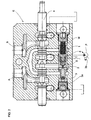
- figure 2 shows a sectional view through a section of the directional control valve object of the present invention.
- With reference to figure 1, the hydraulic circuit of a directional control valve (V) is shown, in which P designates a variable displacement pump that is hydraulically controlled and driven by means of the pressurised oil coming from line C.
- The directional control valve is specifically composed of three sections E1, E2, E3, each one of which is connected to respective workports through the connections A1-B1, A2-B2, A3-B3.
- Each section is equipped with a six-way, three-position spool 4, a
pressure compensator 3 and apiston 5. - The pump P supplies each spool 4.
- The
pressure compensator 3 is characterised in having inside it a pressure signal selector S with sphere. - This selector S is kept mechanically open by a
piston 5 when the pressure conditions so allow. - According to what is stated, the
piston 5 is inserted in the same bore containing thepressure compensator 3. Moreover, a spring M with negligible force operates on thepiston 5. - The load sensing signal is taken off through holes inside the
pressure compensator 3 itself and not in the body of the directional control valve E. - Through the above holes, the pressure signal arrives to both sides of the
pressure compensator 3. - On
side 3a, where the resulting action is the opening of the orifice by means of thepressure compensator 3 itself, the signal directly arrives, taken off frompoint 2 upstream of the pressure compensator 3 (namely betweenpressure compensator 3 and spool 4), while on the other side the signal, still taken off frompoint 2, must pass through the selector S. - In practice, the selector S would not allow the passage of pressure incoming from
point 2 if it were not been kept mechanically open by thepiston 5 that is pressed against thepressure compensator 3 by the workport pressure taken off frompoint 1. - Supposing to actuate the spool 4 of the section E1, the pressure of the respective workport, taken off from
point 1, arrives on the spring M side, namely arrives to operate on thepiston 5 that in such a way presses against thepressure compensator 3 and keeps the selector S open by connectingpoint 2 to line C of the load sensing signal. - The
piston 5 pushed against thepressure compensator 3 makes the group composed ofpressure compensator 3 andpiston 5 operate as a check valve. - Through the line C the pressure in
point 2, namely between spool 4 andpressure compensator 3, arrives to the pump pressure compensator 3P, or alternatively, in case of fixed displacement pump, to the pressure compensator in the inlet cover, and is inserted betweenpressure compensator 3 andpiston 5 of the other sections E2 and E3. - In the described configuration, the
piston 5 of each section E2 and E3 is detached from thecorresponding pressure compensator 3, so that thepressure compensator 3 finds itself with the load sensing signal at one end and the pressure upstream of thepressure compensator 3 itself at theother end 3a, with the result of operating as pressure compensator. - In this arrangement, in
point 2 of sections E2 and E3 the pressure compensator imposes the same pressure inpoint 2 of the section with higher pressure E1 and the selector S inside thepressure compensators 3 of the sections E2 and E3 closes the connection betweenpoints 2 and line C of the load sensing signal. - A second section E2, with a lower workport pressure, is now assumed to be actuated: this pressure, taken off from
point 1, arrives to the spring side of itsown piston 5 that, being by hypothesis lower, does not move thepiston 5 and the situation remains unchanged as previously stated. - On the contrary, it is now assumed to actuate an section E3 with higher pressure: a transient occurs in which the pressure in
point 1 is greater than the pump delivery pressure with the risk of an undesired load dipping. - However, in section E3, the pressure in 1 moves its
own piston 5 against itsown pressure compensator 3 closing the orifice by means of thepressure compensator 3 itself towards the workport, thereby operating as check valve and preventing the load dipping. - Being no flow through the
pressure compensator 3, the pressure in 2 reaches the pump delivery pressure, namely a pressure that is higher than the load sensing signal pressure of line C by an amount equal to the stand-by value, so that the selector S sphere opens till it joins the piston allowing such pressure to arrive at line C and to "short-circuit" towards the pump P itself, generating a pressure increase. - Only when the pressure in 2 exceeds the workport pressure, will the orifice towards the workport itself be opened again, confirming the behaviour as check valve.
- At the same time, the load sensing signal of line C, being increased, detaches the
piston 5 from thepressure compensator 3 in the section E1 that was previously at higher pressure, the selector S closes and thepressure compensator 3 detects the load sensing signal at one end and the pressure in point 2 (namely between spool 4 and pressure compensator 3) on theother end 3a, thereby operating as pressure compensator. - Due to what has been stated above, it must be summarised that in the directional control valve V of the invention, the section with higher pressure has its
pressure compensator 3 that remains joined to thepiston 5 in order to operate as check valve, while for the remaining sections, at lower pressures, thepressure compensator 3 is detached from itscorresponding piston 5, by means of the load sensing signal arriving from line C, thereby operating as pressure compensator. - With reference to figure 2, a sectional view through a section E of the directional control valve V of the invention is shown, in which the previously-described components can be found.
- In particular it is possible to note the arrangement of spool 4,
pressure compensator 3 with selector S obtained (of which the sphere of said selector S is shown) andpiston 5 with spring M beside. - From this, the evident constructive advantage of the directional control valve V of the invention can be observed, since this simple circuit has only two bores where in one bore the spool 4 is inserted and in the other
bore pressure compensator 3 with its related selector S andpiston 5 are inserted.
Claims (7)
- Anti-saturation directional control valve(V) composed of two or more sections with pressure selector compensator; each section (E1, E2, E3) is composed of a six-way, two-position spool (4) of a proportional type, a compensator (3) that performs the function of pressure compensator, characterised in that the pressure compensator (3) comprises therein a pressure signal selector (S), kept mechanically open or not by a piston (5) with spring (M), with a negligible force, depending on the pressure on the workports.
- Anti-saturation directional control valve(V) according to claim 1, characterised in that the workport pressure of its own section operates on piston (5), namely on the spring (M) side, such pressure being taken off from point 1, namely between pressure compensator (3) and workport, the pressure upstream of the pressure compensator (3) operates on the side 3a of the pressure compensator (3) itself, such pressure being taken off from point 2, namely between spool (4) and pressure compensator (3), while the load sensing signal pressure operates between piston (5) and pressure compensator (3).
- Anti-saturation directional control valve(V) according to claim 1 and 2, characterised in that the piston (5) presses against the selector (S) of the pressure compensator (3) in the section with higher pressure and the group composed of pressure compensator (3) and piston (5) operates as check valve.
- Anti-saturation directional control valve(V) according to claim 1, 2 and 3, characterised in that the selector (S), kept open by the piston (5), connects the pressure signal in point 2, between spool (4) and pressure compensator (3), to the line (C) of the load sensing signal; said signal arrives to the pump pressure compensator 3P or alternatively, in case of fixed displacement pump, to the pressure compensator in the inlet cover, and acts between pressure compensator (3) and piston (5) of the lower pressure sections (E) of the directional control valve(V).
- Anti-saturation directional control valve (V) according to any one of claims 1 to 4, characterised in that the piston (5) is detached from the pressure compensator (3) in the sections of the directional control valve (V) that are at a lower pressure; in such a way, the selector (S) closes and the pressure compensator (3) performs its own function of pressure compensator.
- Anti-saturation directional control valve (V) according to anyone of claims 1 to 5, characterised in that the pressure compensator (3), the related selector (S) with sphere, the piston (5) and the spring (M) are inserted in the same bore of the pressure compensator (3).
- Anti-saturation directional control valve (V) according to anyone of claims 1 to 6, characterised in that the spring (M) operates on the piston (5) and is arranged as in a check valve.
Applications Claiming Priority (1)
| Application Number | Priority Date | Filing Date | Title |
|---|---|---|---|
| US10/919,346 US7182097B2 (en) | 2004-08-17 | 2004-08-17 | Anti-saturation directional control valve composed of two or more sections with pressure selector compensators |
Publications (2)
| Publication Number | Publication Date |
|---|---|
| EP1628018A1 true EP1628018A1 (en) | 2006-02-22 |
| EP1628018B1 EP1628018B1 (en) | 2007-08-22 |
Family
ID=35295745
Family Applications (1)
| Application Number | Title | Priority Date | Filing Date |
|---|---|---|---|
| EP20050013972 Expired - Lifetime EP1628018B1 (en) | 2004-08-17 | 2005-06-28 | Anti-saturation directional control valve composed of two or more sections with pressure selector compensators |
Country Status (5)
| Country | Link |
|---|---|
| US (1) | US7182097B2 (en) |
| EP (1) | EP1628018B1 (en) |
| AT (1) | ATE371116T1 (en) |
| DE (1) | DE602005002097T2 (en) |
| ES (1) | ES2292009T3 (en) |
Cited By (7)
| Publication number | Priority date | Publication date | Assignee | Title |
|---|---|---|---|---|
| WO2009001377A1 (en) * | 2007-06-26 | 2008-12-31 | Walvoil S.P.A. | Load sensing directional control valve with an element having priority under saturation conditions |
| WO2011026947A1 (en) | 2009-09-03 | 2011-03-10 | Brevini Fluid Power S.P.A. | Distribution valve |
| EP2522860A1 (en) | 2011-05-13 | 2012-11-14 | Walvoil S.p.A. | Hydraulic distributor having a connection parallel to the recesses adjusting the flow rate of the slide and to the local compensator |
| EP2918853A1 (en) * | 2014-03-11 | 2015-09-16 | Bucher Hydraulics S.p.A. | Hydraulic section for load sensing applications and multiple hydraulic distributor |
| EP2980416A1 (en) * | 2014-07-31 | 2016-02-03 | Bucher Hydraulics S.p.A. | Hydraulic section for load sensing applications and multiple hydraulic distributor |
| EP3076028A1 (en) | 2015-04-02 | 2016-10-05 | Walvoil S.p.A. | Hydraulic valve device with multiple working sections |
| CN114911165A (en) * | 2022-05-09 | 2022-08-16 | 北京航空航天大学 | An anti-saturation control method and device for an aero propulsion system test bench |
Families Citing this family (10)
| Publication number | Priority date | Publication date | Assignee | Title |
|---|---|---|---|---|
| US7168250B2 (en) * | 2005-04-21 | 2007-01-30 | International Engine Intellectual Property Company, Llc | Engine valve system and method |
| ITPR20060036A1 (en) | 2006-04-12 | 2007-10-13 | Walvoil Spa | PRESSURE COMPENSATOR WITH DIFFERENTIAL AREAS PILOTED AND ITS PILOT SYSTEM. |
| US7854115B2 (en) * | 2008-04-25 | 2010-12-21 | Husco International, Inc. | Post-pressure compensated hydraulic control valve with load sense pressure limiting |
| KR101852529B1 (en) | 2010-03-17 | 2018-04-27 | 파커-한니핀 코포레이션 | Hydraulic valve with pressure limiter |
| JP6425500B2 (en) * | 2014-11-07 | 2018-11-21 | Kyb株式会社 | Load sensing valve device |
| US10989232B2 (en) | 2015-09-18 | 2021-04-27 | Rost Innovation LLC | Control valve compensation system |
| US10385884B2 (en) | 2015-09-18 | 2019-08-20 | Rost Innovation LLC | Control valve compensation system |
| DE102018202148B3 (en) * | 2018-02-12 | 2019-03-07 | Hawe Hydraulik Se | Hydraulic valve assembly with forced switching and mobile hydraulic system |
| IT202100009830A1 (en) * | 2021-04-19 | 2022-10-19 | Walvoil Spa | HYDRAULIC DISTRIBUTOR WITH COMPENSATING DEVICE FOR DIRECTIONAL VALVES |
| CN114439790A (en) * | 2022-03-09 | 2022-05-06 | 中信机电制造公司科研设计院 | Hydraulic system for winch operation of rescue vehicle |
Citations (4)
| Publication number | Priority date | Publication date | Assignee | Title |
|---|---|---|---|---|
| DE4234037A1 (en) * | 1992-10-09 | 1994-04-14 | Rexroth Mannesmann Gmbh | Hydraulic valve system for mobile equipment - has monoblock construction with pair of parallel spools one of which is used for load and second as regulating stage |
| US5890362A (en) * | 1997-10-23 | 1999-04-06 | Husco International, Inc. | Hydraulic control valve system with non-shuttle pressure compensator |
| US6532989B1 (en) * | 1998-12-09 | 2003-03-18 | Mannesmann Rexroth S.A. | Hydraulic distributor |
| US20040040294A1 (en) * | 2000-09-29 | 2004-03-04 | Toyoaki Sagawa | Hydraulic controller |
Family Cites Families (7)
| Publication number | Priority date | Publication date | Assignee | Title |
|---|---|---|---|---|
| DE4005967C2 (en) * | 1990-02-26 | 1996-05-09 | Rexroth Mannesmann Gmbh | Control arrangement for several hydraulic consumers |
| FR2694606B1 (en) * | 1992-08-04 | 1994-11-04 | Bennes Marrel | Control assembly for a plurality of hydraulic receivers. |
| FR2744497B1 (en) * | 1996-02-07 | 1998-04-03 | Rexroth Sigma | MULTIPLE HYDRAULIC DISTRIBUTION DEVICE |
| DE19646445A1 (en) * | 1996-11-11 | 1998-05-14 | Rexroth Mannesmann Gmbh | Valve arrangement |
| US5715865A (en) * | 1996-11-13 | 1998-02-10 | Husco International, Inc. | Pressure compensating hydraulic control valve system |
| US5715862A (en) * | 1996-11-25 | 1998-02-10 | Carrier Corporation | Bidirectional flow control device |
| US5857488A (en) * | 1997-06-26 | 1999-01-12 | Kobelt; Jacob | Multi-mode selector valve assembly for marine steering system |
-
2004
- 2004-08-17 US US10/919,346 patent/US7182097B2/en not_active Expired - Lifetime
-
2005
- 2005-06-28 DE DE200560002097 patent/DE602005002097T2/en not_active Expired - Lifetime
- 2005-06-28 ES ES05013972T patent/ES2292009T3/en not_active Expired - Lifetime
- 2005-06-28 AT AT05013972T patent/ATE371116T1/en not_active IP Right Cessation
- 2005-06-28 EP EP20050013972 patent/EP1628018B1/en not_active Expired - Lifetime
Patent Citations (4)
| Publication number | Priority date | Publication date | Assignee | Title |
|---|---|---|---|---|
| DE4234037A1 (en) * | 1992-10-09 | 1994-04-14 | Rexroth Mannesmann Gmbh | Hydraulic valve system for mobile equipment - has monoblock construction with pair of parallel spools one of which is used for load and second as regulating stage |
| US5890362A (en) * | 1997-10-23 | 1999-04-06 | Husco International, Inc. | Hydraulic control valve system with non-shuttle pressure compensator |
| US6532989B1 (en) * | 1998-12-09 | 2003-03-18 | Mannesmann Rexroth S.A. | Hydraulic distributor |
| US20040040294A1 (en) * | 2000-09-29 | 2004-03-04 | Toyoaki Sagawa | Hydraulic controller |
Cited By (10)
| Publication number | Priority date | Publication date | Assignee | Title |
|---|---|---|---|---|
| WO2009001377A1 (en) * | 2007-06-26 | 2008-12-31 | Walvoil S.P.A. | Load sensing directional control valve with an element having priority under saturation conditions |
| US8375975B2 (en) | 2007-06-26 | 2013-02-19 | Walvoil S.P.A. | Load sensing directional control valve with an element having priority under saturation conditions |
| WO2011026947A1 (en) | 2009-09-03 | 2011-03-10 | Brevini Fluid Power S.P.A. | Distribution valve |
| EP2522860A1 (en) | 2011-05-13 | 2012-11-14 | Walvoil S.p.A. | Hydraulic distributor having a connection parallel to the recesses adjusting the flow rate of the slide and to the local compensator |
| EP2918853A1 (en) * | 2014-03-11 | 2015-09-16 | Bucher Hydraulics S.p.A. | Hydraulic section for load sensing applications and multiple hydraulic distributor |
| US10100496B2 (en) | 2014-03-11 | 2018-10-16 | Bucher Hydraulics S.P.A. | Hydraulic section for load sensing applications and multiple hydraulic distributor |
| EP2980416A1 (en) * | 2014-07-31 | 2016-02-03 | Bucher Hydraulics S.p.A. | Hydraulic section for load sensing applications and multiple hydraulic distributor |
| EP3076028A1 (en) | 2015-04-02 | 2016-10-05 | Walvoil S.p.A. | Hydraulic valve device with multiple working sections |
| CN114911165A (en) * | 2022-05-09 | 2022-08-16 | 北京航空航天大学 | An anti-saturation control method and device for an aero propulsion system test bench |
| CN114911165B (en) * | 2022-05-09 | 2024-06-04 | 北京航空航天大学 | Anti-saturation control method and device for test bed of aviation propulsion system |
Also Published As
| Publication number | Publication date |
|---|---|
| DE602005002097D1 (en) | 2007-10-04 |
| ATE371116T1 (en) | 2007-09-15 |
| DE602005002097T2 (en) | 2008-05-15 |
| US7182097B2 (en) | 2007-02-27 |
| EP1628018B1 (en) | 2007-08-22 |
| ES2292009T3 (en) | 2008-03-01 |
| US20060037649A1 (en) | 2006-02-23 |
Similar Documents
| Publication | Publication Date | Title |
|---|---|---|
| EP1628018B1 (en) | Anti-saturation directional control valve composed of two or more sections with pressure selector compensators | |
| US7752842B2 (en) | Circuit for controlling a double-action hydraulic drive cylinder | |
| US5138837A (en) | Load independent valve control for a plurality of hydraulic users | |
| EP2078868B1 (en) | Hydraulic control valve system with isolated pressure compensation | |
| CN111033056B (en) | Hydraulic circuit | |
| US10590962B2 (en) | Directional control valve | |
| US10473125B2 (en) | Hydraulic actuator control circuit | |
| US6782697B2 (en) | Pressure-compensating valve with load check | |
| CA2241248A1 (en) | Pressure compensating hydraulic control valve system | |
| US11280354B2 (en) | Hydraulic valve with pressure limiter function | |
| US20180282974A1 (en) | Fluid pressure control device | |
| JP2744004B2 (en) | Hydraulic pressure control device | |
| US5592967A (en) | Control valve with variable priority function | |
| JP2000055002A (en) | Hydrostatic drive system | |
| JPH04248004A (en) | Valve system for controlling liquid pressure independent of load exerted by a plurality of liquid pressure actuator | |
| KR100652871B1 (en) | Flow control device for construction equipment | |
| CN116771741B (en) | Hydraulic system | |
| DE102007035971A1 (en) | Control arrangement and method for controlling at least two hydraulic consumers | |
| US7219593B2 (en) | Saturation-proof hydraulic control device that is composed of two or more elements | |
| US7249554B2 (en) | Hydraulic control arrangement | |
| EP2005006B1 (en) | Pilot-operated differential-area pressure compensator and control system for piloting same | |
| US20120205563A1 (en) | Valve arrangement for actuating a load | |
| CN216642613U (en) | Hydraulic logic valve block | |
| US12565903B2 (en) | Fluid pressure control device | |
| JP2537219B2 (en) | Hydraulic cylinder hydraulic control device |
Legal Events
| Date | Code | Title | Description |
|---|---|---|---|
| PUAI | Public reference made under article 153(3) epc to a published international application that has entered the european phase |
Free format text: ORIGINAL CODE: 0009012 |
|
| AK | Designated contracting states |
Kind code of ref document: A1 Designated state(s): AT BE BG CH CY CZ DE DK EE ES FI FR GB GR HU IE IS IT LI LT LU MC NL PL PT RO SE SI SK TR |
|
| AX | Request for extension of the european patent |
Extension state: AL BA HR LV MK YU |
|
| 17P | Request for examination filed |
Effective date: 20060517 |
|
| 17Q | First examination report despatched |
Effective date: 20060627 |
|
| AKX | Designation fees paid |
Designated state(s): AT BE BG CH CY CZ DE DK EE ES FI FR GB GR HU IE IS IT LI LT LU MC NL PL PT RO SE SI SK TR |
|
| GRAP | Despatch of communication of intention to grant a patent |
Free format text: ORIGINAL CODE: EPIDOSNIGR1 |
|
| GRAS | Grant fee paid |
Free format text: ORIGINAL CODE: EPIDOSNIGR3 |
|
| GRAA | (expected) grant |
Free format text: ORIGINAL CODE: 0009210 |
|
| AK | Designated contracting states |
Kind code of ref document: B1 Designated state(s): AT BE BG CH CY CZ DE DK EE ES FI FR GB GR HU IE IS IT LI LT LU MC NL PL PT RO SE SI SK TR |
|
| REG | Reference to a national code |
Ref country code: GB Ref legal event code: FG4D |
|
| REG | Reference to a national code |
Ref country code: CH Ref legal event code: EP |
|
| REG | Reference to a national code |
Ref country code: IE Ref legal event code: FG4D |
|
| REF | Corresponds to: |
Ref document number: 602005002097 Country of ref document: DE Date of ref document: 20071004 Kind code of ref document: P |
|
| REG | Reference to a national code |
Ref country code: DE Ref legal event code: R096 Ref document number: 602005002097 Country of ref document: DE Effective date: 20071004 |
|
| ET | Fr: translation filed | ||
| PG25 | Lapsed in a contracting state [announced via postgrant information from national office to epo] |
Ref country code: LT Free format text: LAPSE BECAUSE OF FAILURE TO SUBMIT A TRANSLATION OF THE DESCRIPTION OR TO PAY THE FEE WITHIN THE PRESCRIBED TIME-LIMIT Effective date: 20070822 Ref country code: NL Free format text: LAPSE BECAUSE OF FAILURE TO SUBMIT A TRANSLATION OF THE DESCRIPTION OR TO PAY THE FEE WITHIN THE PRESCRIBED TIME-LIMIT Effective date: 20070822 Ref country code: IS Free format text: LAPSE BECAUSE OF FAILURE TO SUBMIT A TRANSLATION OF THE DESCRIPTION OR TO PAY THE FEE WITHIN THE PRESCRIBED TIME-LIMIT Effective date: 20071222 Ref country code: FI Free format text: LAPSE BECAUSE OF FAILURE TO SUBMIT A TRANSLATION OF THE DESCRIPTION OR TO PAY THE FEE WITHIN THE PRESCRIBED TIME-LIMIT Effective date: 20070822 Ref country code: BG Free format text: LAPSE BECAUSE OF FAILURE TO SUBMIT A TRANSLATION OF THE DESCRIPTION OR TO PAY THE FEE WITHIN THE PRESCRIBED TIME-LIMIT Effective date: 20071122 |
|
| NLV1 | Nl: lapsed or annulled due to failure to fulfill the requirements of art. 29p and 29m of the patents act | ||
| PG25 | Lapsed in a contracting state [announced via postgrant information from national office to epo] |
Ref country code: CH Free format text: LAPSE BECAUSE OF FAILURE TO SUBMIT A TRANSLATION OF THE DESCRIPTION OR TO PAY THE FEE WITHIN THE PRESCRIBED TIME-LIMIT Effective date: 20070822 Ref country code: LI Free format text: LAPSE BECAUSE OF FAILURE TO SUBMIT A TRANSLATION OF THE DESCRIPTION OR TO PAY THE FEE WITHIN THE PRESCRIBED TIME-LIMIT Effective date: 20070822 Ref country code: AT Free format text: LAPSE BECAUSE OF FAILURE TO SUBMIT A TRANSLATION OF THE DESCRIPTION OR TO PAY THE FEE WITHIN THE PRESCRIBED TIME-LIMIT Effective date: 20070822 Ref country code: PL Free format text: LAPSE BECAUSE OF FAILURE TO SUBMIT A TRANSLATION OF THE DESCRIPTION OR TO PAY THE FEE WITHIN THE PRESCRIBED TIME-LIMIT Effective date: 20070822 |
|
| REG | Reference to a national code |
Ref country code: CH Ref legal event code: PL |
|
| REG | Reference to a national code |
Ref country code: ES Ref legal event code: FG2A Ref document number: 2292009 Country of ref document: ES Kind code of ref document: T3 |
|
| PG25 | Lapsed in a contracting state [announced via postgrant information from national office to epo] |
Ref country code: BE Free format text: LAPSE BECAUSE OF FAILURE TO SUBMIT A TRANSLATION OF THE DESCRIPTION OR TO PAY THE FEE WITHIN THE PRESCRIBED TIME-LIMIT Effective date: 20070822 |
|
| PG25 | Lapsed in a contracting state [announced via postgrant information from national office to epo] |
Ref country code: GR Free format text: LAPSE BECAUSE OF FAILURE TO SUBMIT A TRANSLATION OF THE DESCRIPTION OR TO PAY THE FEE WITHIN THE PRESCRIBED TIME-LIMIT Effective date: 20071123 Ref country code: DK Free format text: LAPSE BECAUSE OF FAILURE TO SUBMIT A TRANSLATION OF THE DESCRIPTION OR TO PAY THE FEE WITHIN THE PRESCRIBED TIME-LIMIT Effective date: 20070822 |
|
| PG25 | Lapsed in a contracting state [announced via postgrant information from national office to epo] |
Ref country code: SK Free format text: LAPSE BECAUSE OF FAILURE TO SUBMIT A TRANSLATION OF THE DESCRIPTION OR TO PAY THE FEE WITHIN THE PRESCRIBED TIME-LIMIT Effective date: 20070822 Ref country code: CZ Free format text: LAPSE BECAUSE OF FAILURE TO SUBMIT A TRANSLATION OF THE DESCRIPTION OR TO PAY THE FEE WITHIN THE PRESCRIBED TIME-LIMIT Effective date: 20070822 Ref country code: PT Free format text: LAPSE BECAUSE OF FAILURE TO SUBMIT A TRANSLATION OF THE DESCRIPTION OR TO PAY THE FEE WITHIN THE PRESCRIBED TIME-LIMIT Effective date: 20080122 |
|
| PLBE | No opposition filed within time limit |
Free format text: ORIGINAL CODE: 0009261 |
|
| STAA | Information on the status of an ep patent application or granted ep patent |
Free format text: STATUS: NO OPPOSITION FILED WITHIN TIME LIMIT |
|
| PG25 | Lapsed in a contracting state [announced via postgrant information from national office to epo] |
Ref country code: RO Free format text: LAPSE BECAUSE OF FAILURE TO SUBMIT A TRANSLATION OF THE DESCRIPTION OR TO PAY THE FEE WITHIN THE PRESCRIBED TIME-LIMIT Effective date: 20070822 Ref country code: SE Free format text: LAPSE BECAUSE OF FAILURE TO SUBMIT A TRANSLATION OF THE DESCRIPTION OR TO PAY THE FEE WITHIN THE PRESCRIBED TIME-LIMIT Effective date: 20071122 |
|
| 26N | No opposition filed |
Effective date: 20080526 |
|
| REG | Reference to a national code |
Ref country code: DE Ref legal event code: R097 Ref document number: 602005002097 Country of ref document: DE Effective date: 20080526 |
|
| PG25 | Lapsed in a contracting state [announced via postgrant information from national office to epo] |
Ref country code: MC Free format text: LAPSE BECAUSE OF NON-PAYMENT OF DUE FEES Effective date: 20080630 |
|
| PG25 | Lapsed in a contracting state [announced via postgrant information from national office to epo] |
Ref country code: IE Free format text: LAPSE BECAUSE OF NON-PAYMENT OF DUE FEES Effective date: 20080630 Ref country code: EE Free format text: LAPSE BECAUSE OF FAILURE TO SUBMIT A TRANSLATION OF THE DESCRIPTION OR TO PAY THE FEE WITHIN THE PRESCRIBED TIME-LIMIT Effective date: 20070822 |
|
| PG25 | Lapsed in a contracting state [announced via postgrant information from national office to epo] |
Ref country code: SI Free format text: LAPSE BECAUSE OF FAILURE TO SUBMIT A TRANSLATION OF THE DESCRIPTION OR TO PAY THE FEE WITHIN THE PRESCRIBED TIME-LIMIT Effective date: 20070822 |
|
| PG25 | Lapsed in a contracting state [announced via postgrant information from national office to epo] |
Ref country code: CY Free format text: LAPSE BECAUSE OF FAILURE TO SUBMIT A TRANSLATION OF THE DESCRIPTION OR TO PAY THE FEE WITHIN THE PRESCRIBED TIME-LIMIT Effective date: 20070822 |
|
| PGFP | Annual fee paid to national office [announced via postgrant information from national office to epo] |
Ref country code: ES Payment date: 20090623 Year of fee payment: 5 |
|
| PG25 | Lapsed in a contracting state [announced via postgrant information from national office to epo] |
Ref country code: HU Free format text: LAPSE BECAUSE OF FAILURE TO SUBMIT A TRANSLATION OF THE DESCRIPTION OR TO PAY THE FEE WITHIN THE PRESCRIBED TIME-LIMIT Effective date: 20080223 Ref country code: LU Free format text: LAPSE BECAUSE OF NON-PAYMENT OF DUE FEES Effective date: 20080628 |
|
| REG | Reference to a national code |
Ref country code: ES Ref legal event code: FD2A Effective date: 20110715 |
|
| PG25 | Lapsed in a contracting state [announced via postgrant information from national office to epo] |
Ref country code: ES Free format text: LAPSE BECAUSE OF NON-PAYMENT OF DUE FEES Effective date: 20110705 |
|
| PG25 | Lapsed in a contracting state [announced via postgrant information from national office to epo] |
Ref country code: ES Free format text: LAPSE BECAUSE OF NON-PAYMENT OF DUE FEES Effective date: 20100629 |
|
| REG | Reference to a national code |
Ref country code: FR Ref legal event code: PLFP Year of fee payment: 12 |
|
| REG | Reference to a national code |
Ref country code: DE Ref legal event code: R082 Ref document number: 602005002097 Country of ref document: DE Representative=s name: GLAWE DELFS MOLL PARTNERSCHAFT MBB VON PATENT-, DE Ref country code: DE Ref legal event code: R082 Ref document number: 602005002097 Country of ref document: DE Representative=s name: RAIBLE, DEISSLER, LEHMANN PATENTANWAELTE PARTG, DE Ref country code: DE Ref legal event code: R082 Ref document number: 602005002097 Country of ref document: DE Representative=s name: RDL PATENTANWAELTE PARTG MBB, DE |
|
| REG | Reference to a national code |
Ref country code: DE Ref legal event code: R082 Ref document number: 602005002097 Country of ref document: DE Representative=s name: RAIBLE, DEISSLER, LEHMANN PATENTANWAELTE PARTG, DE Ref country code: DE Ref legal event code: R082 Ref document number: 602005002097 Country of ref document: DE Representative=s name: RDL PATENTANWAELTE PARTG MBB, DE |
|
| REG | Reference to a national code |
Ref country code: FR Ref legal event code: PLFP Year of fee payment: 13 |
|
| REG | Reference to a national code |
Ref country code: FR Ref legal event code: PLFP Year of fee payment: 14 |
|
| P01 | Opt-out of the competence of the unified patent court (upc) registered |
Effective date: 20230622 |
|
| PGFP | Annual fee paid to national office [announced via postgrant information from national office to epo] |
Ref country code: GB Payment date: 20240619 Year of fee payment: 20 |
|
| PGFP | Annual fee paid to national office [announced via postgrant information from national office to epo] |
Ref country code: DE Payment date: 20240619 Year of fee payment: 20 |
|
| PGFP | Annual fee paid to national office [announced via postgrant information from national office to epo] |
Ref country code: FR Payment date: 20240628 Year of fee payment: 20 |
|
| PGFP | Annual fee paid to national office [announced via postgrant information from national office to epo] |
Ref country code: TR Payment date: 20240621 Year of fee payment: 20 |
|
| PGFP | Annual fee paid to national office [announced via postgrant information from national office to epo] |
Ref country code: IT Payment date: 20240625 Year of fee payment: 20 |
|
| REG | Reference to a national code |
Ref country code: DE Ref legal event code: R071 Ref document number: 602005002097 Country of ref document: DE |
|
| PG25 | Lapsed in a contracting state [announced via postgrant information from national office to epo] |
Ref country code: GB Free format text: LAPSE BECAUSE OF EXPIRATION OF PROTECTION Effective date: 20250627 |
|
| REG | Reference to a national code |
Ref country code: GB Ref legal event code: PE20 Expiry date: 20250627 |