EP2201176B1 - Bohle für einen deckenfertiger - Google Patents
Bohle für einen deckenfertiger Download PDFInfo
- Publication number
- EP2201176B1 EP2201176B1 EP07818213.6A EP07818213A EP2201176B1 EP 2201176 B1 EP2201176 B1 EP 2201176B1 EP 07818213 A EP07818213 A EP 07818213A EP 2201176 B1 EP2201176 B1 EP 2201176B1
- Authority
- EP
- European Patent Office
- Prior art keywords
- sectors
- extendible
- screed
- central
- sector
- Prior art date
- Legal status (The legal status is an assumption and is not a legal conclusion. Google has not performed a legal analysis and makes no representation as to the accuracy of the status listed.)
- Not-in-force
Links
- 239000000463 material Substances 0.000 claims description 34
- 239000007787 solid Substances 0.000 claims description 5
- 238000007667 floating Methods 0.000 claims description 3
- 238000010438 heat treatment Methods 0.000 claims description 2
- 230000008878 coupling Effects 0.000 description 2
- 238000010168 coupling process Methods 0.000 description 2
- 238000005859 coupling reaction Methods 0.000 description 2
- 238000006073 displacement reaction Methods 0.000 description 2
- 238000000465 moulding Methods 0.000 description 2
- 239000010426 asphalt Substances 0.000 description 1
- 238000005516 engineering process Methods 0.000 description 1
- 238000000034 method Methods 0.000 description 1
- 230000000717 retained effect Effects 0.000 description 1
- 230000001360 synchronised effect Effects 0.000 description 1
- 238000011144 upstream manufacturing Methods 0.000 description 1
Images


Classifications
-
- E—FIXED CONSTRUCTIONS
- E01—CONSTRUCTION OF ROADS, RAILWAYS, OR BRIDGES
- E01C—CONSTRUCTION OF, OR SURFACES FOR, ROADS, SPORTS GROUNDS, OR THE LIKE; MACHINES OR AUXILIARY TOOLS FOR CONSTRUCTION OR REPAIR
- E01C19/00—Machines, tools or auxiliary devices for preparing or distributing paving materials, for working the placed materials, or for forming, consolidating, or finishing the paving
- E01C19/48—Machines, tools or auxiliary devices for preparing or distributing paving materials, for working the placed materials, or for forming, consolidating, or finishing the paving for laying-down the materials and consolidating them, or finishing the surface, e.g. slip forms therefor, forming kerbs or gutters in a continuous operation in situ
-
- E—FIXED CONSTRUCTIONS
- E01—CONSTRUCTION OF ROADS, RAILWAYS, OR BRIDGES
- E01C—CONSTRUCTION OF, OR SURFACES FOR, ROADS, SPORTS GROUNDS, OR THE LIKE; MACHINES OR AUXILIARY TOOLS FOR CONSTRUCTION OR REPAIR
- E01C2301/00—Machine characteristics, parts or accessories not otherwise provided for
- E01C2301/14—Extendable screeds
- E01C2301/16—Laterally slidable screeds
Definitions
- the present invention refers to a screed of a paver finisher according to the main claim.
- the paver finisher with such a screed also being part of the present invention.
- An extendible screed generally consists of a central fixed section, which determines the basic laying width, and of at least two sections which move perpendicularly to the centre line of the machine, sliding on a guide set, integral with the central section.
- An extendible screed generally consists of a central fixed section, which determines the basic laying width, and of at least two sections which move perpendicularly to the centre line of the machine, sliding on a guide set, integral with the central section.
- the maximum laying width that can be achieved by an extendible screed, as described above and without the application of additional extensions, is equal to or less than twice its basic width.
- the scope of the present invention is to avoid such disadvantages, realising an improved apparatus and machine.
- the invention is characterised by the main claim, whose combined features allow all the problems described above to be solved.
- the present invention applying one ahead the other two extension screeds (1c,1d) ahead of a central screed (1 a, 1 b), and behind auger means with respective extensions (Sc1,Sc2), completely eliminates the aforementioned problems and allows a compact machine to be made that is capable of extending the laying width of a road pavement up to a maximum of 2.5 times the basic width of its screed avoiding all the drawbacks of both previous solutions.
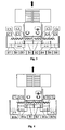
- a paver finisher ( Fig.1 ) is a machine of known technology which always consists of two main units:
- the overall transport width of the machine must comply with the limits allowed by the different countries, whilst the paving width must be advantageously wider to cover at least a road lane in a single pass.
- the screed must therefore be engineered so as to adjust its width to that more conveniently required by the work specifications.
- the extendible screeds consist of a central fixed sector, in turn consisting of two hinged sectors (B1) and (B2), connected to the tractor by two tow arms (A1) and (A2), and by two sectors (B3) and (B4) mobile in the direction of the laying width.
- the central sectors can be located ahead of the mobile sectors ( Fig. 1 ), or behind them ( Fig. 2 ) respectively.
- Each tow arm is rigidly connected to the central section of the screed, whilst the connection to the tractor is made through a ball joint which can be moved vertically.
- This type of constraint gives the screed a floating movement.
- the movement of the tractor (in the direction of the arrow) forces the screed to climb over the material with an angle of attack " ⁇ ", which is determined by the balance of the forces acting on the screed: tow force, screed weight, material resistance, material carrying capacity.
- the extendible sectors (B3) and (B4) generally move with respect to the central section by means of hydraulic cylinders, or by other known systems.
- the most common screeds can extend their basic width (L) up to twice (2L). Wider laying widths can be obtained by fitting individual extensions (B5, B6, B7, B8, ...) and the relevant necessary auger sectors (C5, C6, C7, C8, .).
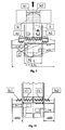
- the invention as substantially shown in Fig. 6 , use an opposite solution compared to the solutions of the prior art and particularly to the solution claimed in the patent US 659571 , by eliminating the disadvantages and the complexity of an intermediate moulding board and locating the extendible sectors ahead of the central fixed sector, with reference to the paving direction of progress.
- the screed of the present invention can be applied indifferently to any paver finisher, of the known art, equipped with:
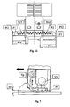
- the preferential solution ( Fig. 6 ) provides that the augers consist of two main elements (C1) and (C2) and of two auxiliary extendible side elements (2c) and (2d), where the function of said auxiliary elements can be replaced by an alternative less advantageous solution, consisting of sectors (Sc1) and (Sc2) to be applied only when needed, according to the know art, as shown in Fig. 10 .
- the screed (B) ( Fig. 5 ) comprises a central fixed section, with a central hinge (Ac) ( Fig. 6 ) on the centre line of the machine to constitute two sections (1 a) and (1 b), connected to the tow arms (A1) and (A2) respectively, plus two said mobile sectors (1 c) and (1 d) which can be extended in the direction perpendicular to the machine centre line, i.e. in the direction of the pavement width.
- an actuator of the known art by means of the hinge (Ac) can make an angle between the screed bottom plates of left sections (1 a + 1c) and of right sections (1 b + 1d) so as to make linear, convex, or concave ( Fig. 6a ) pavement section profiles.
- the mobile sectors (1c) and (1d) are located ahead of the central fixed sectors (1a) and (1b); sector (1c) is in turn located ahead of sector (1d).
- the positions of sectors (1c) and (1d) can be interchanged, giving a totally equivalent functional solution.
- the screed end plates (3a) and (3b) are connected to the mobile sectors (1c) and (1d) respectively.
- the mobile sectors (1c) and (1d) each have a length about equal to that of the central sector (1 a + 1 b), of basic paving width "L", it is therefore possible to extend the overall paving width up to a value equal to or wider than 2.5 times the basic paving width "L".
- Fig. 7 The characteristic items of a screed sector are schematically shown in Fig. 7 .
- the material, spread by the augers in front of the screed is forced by the tow action of the tractor to flow under the screed bottom plate (Pl), the flow being made easier by the alternate vertical movement of a tamper bar (Tp) which slightly extends underneath the leading edge of the screed bottom plate.
- Tp tamper bar
- Some screed versions do not include the tamper bar, and the flow of the material under the screed bottom plate is simply facilitated by the inclination " ⁇ " that is maintained by the plate with reference to the laying plane.
- Angle " ⁇ " (angle of attack) is characteristic of any screed and represents the inclination assumed by the screed plate when all forces are balanced (traction, screed weight, resistance of material in front of the screed, friction between screed plate and material, material carrying force).
- Fig. 8 schematically shows how the sliding system of a mobile sector, with reference to the fixed sector, is preferably arranged, in this case sector (1 c) of Fig. 6 .
- Sector (1 c) slides perpendicularly to the machine centre line, guided by a pair of supports (Sa) and (Sb), properly constrained to the support arm (4a).
- Sector (1 d) slides as the above, being properly constrained to the support arm (4b).
- the support arms (4a) and (4b) being rigidly connected to the side ends of the central sectors (1a) and (1b) respectively.
- the core of the mobile screed sector ( Fig. 7 ), which includes the screed plate (PI), the tamper bar (Tp), the vibrators (Vb) and the screed plate heating equipment, is properly connected to the side walls (Wa) and (Wb) of the supporting frame (Ts).
- Said supporting frame comprises the guide (Gm) and an anti-rotation unit (Ar), sliding on bushings within the support (Sb), with wall (Wb) sliding on bushings along the external surface of the guide (Gf).
- the support (Sa) is connected to the support arm (4a), but it can move vertically with respect to the latter (see Fig. 9 ).
- the support (Sb) moves vertically along with the support (Sa), but it is possible to modify its angular position with respect to it around a rotation axis, coinciding with the centre line of the guide (Gf).
- the cylindrical guide (Gf) is rigidly connected to the support (Sa): the hydraulic cylinder (P) being rigidly connected to said guide (Gf) and with the centre line of said cylinder (P) coinciding with the centre line of said guide (Gf).
- the mobile guide (Gm) operated by the cylinder (P), slides on bushings inside the guide (Gf) and along its centre line.
- the section view A-A is shown in Fig. 9 .
- the mobile screed sectors are not aligned crosswise with the central fixed screed sector, therefore it is necessary to adjust their vertical position independently so as to bring the trailed edges (Ua), (Ub), (Uc) of all screed bottom plates (Pl) to lean upon the same plane, as shown in Fig. 9 .
- the support (Sa) can move vertically along guides (Gv) with respect to the support arm (4a), the vertical movement being operated through a screw/nut-screw coupling by the actuator (Rc), or by other known systems with the same function.
- the coupling of the tow arms (A1) and (A2) with the central screed sector is generally made as schematically shown in Fig. 9 .
- a pin (Pn) on each side allows the inclination of the whole screed to be changed with respect to the tow arms (A1) and (A2) and to keep it locked in position by means of the turnbuckles (Tr) (one on each side).
- the support (Sb) can rotate around the centre line of the guide (Gf), dragging in the rotation the lower part of the relevant extendible sector.
- the adjustment is carried out by the screw adjuster (Rg) and by known locking devices (e.g.: bolts) to keep the position.
- known locking devices e.g.: bolts
- mouldboards (Rc) and (Rl) have been provided in order to limit the thickness of the material fed to the central screed sectors (1 a) and (1 b) and to the most backward mobile screed sector (1d).
- the vertical displacement of the mouldboard (Rc) is operated by hydraulic cylinders, or by other known devices (not shown).
- the horizontal guide (Go) is fixed to the mouldboard (Rc); the side mouldboard (Rl) can slide within said guide (Go); said mouldboard (Rl) being moved by the mobile sector (1d) in a direction perpendicular to the machine centre line; on the end plate (3b) of said sector (1d) a constraint is provided which does not hinder the reciprocal movements of the mouldboard (Rl) and the end plate (3b).
- the vertical movements of the mouldboards (Rc) and (Rl) are managed by an automatic control system of the thickness of the material being supplied by the augers to the screed sectors (1a), (1b) and (1d).
- the invention previously schematically shown in Fig. 6 , solves the problem in a very advantageous way compared to the prior solutions.
- the cross beam (5) supporting the auger set (C1) and (C2), is connected to the tractor in such a way as to be moved in a vertical direction.
- Two guides (Gc) are fixed to the cross beam (5); within said guides the support arms (2a) and (2b), of the auxiliary auger sectors (2c) and (2d) respectively, can slide in a direction perpendicular to the machine centre line; said auxiliary auger sectors (2c) and (2d) being located just behind the main augers (C1) and (C2) in the direction of the paving work progress.
- the support arms (2a) and (2b) are independently operated by hydraulic cylinders, or by other known systems.
- the solution allows the auxiliary auger sets to move vertically along with the main augers, whilst the cross movements of the support arms (2a) and (2b) are operated in synchronisation with the movements of the relevant screed mobile sectors whenever they are extended more than a preset value (about 800 mm), or return below said value in the closing phase.
- Fig. 12 compares a solution similar to that of the invention, but with evident disadvantages:
- a screed for a paver finisher ( Fig. 6 ) of the type comprising sectors (1 c) and (1d), independently extendible and retractable, substantially sliding on guides connected to the support arms (4a) and (4b) respectively, in turn solid with the central screed fixed sectors (1 a) and (1 b) respectively.
- Said extendible sectors (1 c) and (1 d) being located one behind the other and ahead of the central fixed screed sectors, in the direction of the paving work progress.
- Said extendible sectors (1 c) and (1 d) therefore being able to have a length similar to that of the whole central sector (1 a + 1 b), having a basic laying width "L".
- Said solution being suitable for obtaining a maximum laying width of at least 2.5 times the basic laying width "L”.
- Said screed ( Fig. 6 ) consisting of:
- a screed as above, where said extendible sectors (1 c), (1 d) are connected to the support arms (4a) e (4b) respectively, which are part of the central section, by means of height adjusting devices (Rc), (Gv) Fig. 9 .; said height adjustment being necessary to obtain the co-planarity of the trailed edges (Uc), (Ud) of the screed bottom plates of the extendible sectors (1c), (1d) respectively with the relevant trailed edges of the bottom plates (Ua) and (Ub) of the central sectors (1 a) and (1 b) respectively.
- each extendible sector is equipped with devices (Sb), (Rg) ( Fig. 9 ) for the fine adjustment of the relevant angle of attack, with respect to the angle of attack " ⁇ ", assumed by the central section.
- Said mouldboard (Rl) being mobile in a vertical direction, solid with the first mouldboard (Rc), and crosswise along with the movement of the extendible section (1d); said mouldboard (Rl) being connected to the end plate (3b).
- Said auxiliary augers (2c) and (2d) being operated together with the main auger sectors (C1) and (C2) respectively and said auxiliary augers being extendible crosswise, in a direction perpendicular to the machine centre line, with movements controlled by the extension, or closing of the relevant mobile screed sectors (1c) and (1d).
- auxiliary augers (2c) and (2d) being supported by arms (2a) and (2b) respectively, sliding within guides (Gc) by means of known devices, where said guides (Gc) are fixed to the crossbeam (5), supporting the main augers (C1) and (C2).
Landscapes
- Engineering & Computer Science (AREA)
- Architecture (AREA)
- Civil Engineering (AREA)
- Structural Engineering (AREA)
- Road Paving Machines (AREA)
Claims (2)
- Abgleichbohle für einen Deckenfertiger mit Sektoren (1c; 1d), die unabhängig voneinander ein- und ausziehbar sind, im wesentlichen auf Führungen gleitend, die mit Stützarmen (4a; 4b) verbunden sind bzw. fest mit den festen Sektoren (1a bzw. 1 b) der zentralen Abgleichbohle verbunden; wobei die ausziehbaren Sektoren (1c; 1 d) hintereinander liegen und vor den zentralen festen Sektoren, in Richtung des Arbeitsfortschritts, wobei die ausziehbaren Sektoren (1c; 1d) in der Lage sind, eine Länge ähnlich der des gesamten zentralen Sektors (1a + 1b) einzunehmen, mit einer Grund-Verlegebreite "L", wobei besagte Lösung zum Erhalten einer maximalen Verlegebreite mindestens 2,5mal so groß wie die Grund-Verlegebreite "L" geeignet ist,
wobei besagte Abgleichbohle des weiteren aus folgendem besteht:- einem zentralen festen Abschnitt mit einer gewissen Grundlänge "L", mit einem zentralen Gelenk (Ac), parallel zur Maschinen-Mittellinie, der zwei gelenkige Einheiten (1a und 1b) bildet, um ein lineares, konvexes oder konkaves Profil des Mattenquerschnitts zu ergeben; besagte Einheiten (1a und 1 b) sind an ihren äußeren Enden mit den Stützarmen (4a; 4b) der ausziehbaren Sektoren (1 c, 1 d, bzw.) versehen; besagte ausziehbare Sektoren (1 c, 1 d) sind mit Zugarmen (A1 bzw. A2) verbunden;- einem ersten ausziehbaren Sektor (1 d), mit einer Länge ungefähr gleich der des gesamten zentralen Sektors (1a + 1 b) und vor diesem in Richtung des Arbeitsfortschritts gelegen;- einem zweiten ausziehbaren Sektor (1c), mit einer Länge ungefähr gleich der des gesamten zentralen Sektors (1a + 1b) und vor dem ersten ausziehbaren Sektor (1 d) in Richtung des Arbeitsfortschritts gelegen;- besagte ausziehbare Sektoren (1c; 1 d) sind unabhängig voneinander gegenüber dem zentralen Sektor (1a + 1b) in Richtung der Verlegebreite und in senkrechter Richtung beweglich;- besagte Abgleichbohlen umfassen eine Abgleichbohlengrundplatte (Pl), eine senkrecht bewegliche Tamperleiste (Tp), die sich etwas unterhalb der Vorderkante des Bodenglättblechs (Pl) erstreckt, Vibratormittel (Vb) und Glättblech-Heizung,- der erste und der zweite ausziehbare Sektor sind mit Seitenwänden (Wa; Wb) eines Tragrahmens (Ts) verbunden;- besagter Tragrahmen umfasst eine erste Führung (Gm) und einen Verdrehschutz (Ar), der auf Laufbuchsen innerhalb einer Stütze (Sb) gleitet, mit einer Wand (Wb), die auf Laufbuchsen entlang der Außenfläche einer zweiten Führung (Gf) gleitet;und wobei besagte ausziehbare Sektoren (1c; 1d) mit den Stützarmen (4a bzw. 4b) verbunden sind, die Teil des Mittelabschnitts sind, mittels Höheneinstellungsvorrichtungen (Rc; Gv), wobei die Höheneinstellung vorgesehen ist, um die Komplanarität der geschleiften Ränder (Uc; Ud) der Bodenplatten der ausziehbaren Sektoren (1c bzw. 1 d) mit denen der Bodenplatten (Ua; Ub) der zentralen Sektoren (1 a bzw. 1 b) zu erhalten;- jeder ausziehbare Sektor ist mit Vorrichtungen (Sb; Rg) zur Feineinstellung des betreffenden Ansatzwinkels ausgestattet, in bezug auf den Ansatzwinkel "ω", den der Mittelabschnitt einnimmt;- besagte ausziehbare Sektoren (1c; 1d) tragen an ihren äußeren Enden Endplatten (3a bzw. 3b), um das Material festzuhalten, das von den Bohrern geliefert wird; wobei die Endplatten in Kontakt mit der zu pflasternden Fläche sind und in senkrechter Richtung frei treiben;und wobei die Höhe der von den Bohrern zum Mittelabschnitt gelieferten Materialschicht von einer Abstreichplatte (Rc) eingestellt wird; besagte Abstreichplatte (Rc) gleitet in senkrechter Richtung in Führungen (Gv), die an Zugarmen (A1, A2) befestigt sind und von hydraulischen Zylindern bewegt werden, oder von gleichwertigen funktionalen Vorrichtungen; besagte Abstreichplatte (Rc) ist mit einer waagrechten Führung (Go) ausgestattet, um eine weitere Abstreichplatte (Rl) abzustützen, so dass die Höhe der von den Bohrern zum hintersten ausziehbaren Sektor (1 d) gelieferten Materialschicht begrenzt wird, in Richtung des Arbeitsfortschritts, besagte Abstreichplatte (Rl) ist in senkrechter Richtung beweglich, einstückig mit der ersten Abstreichplatte (Rc), und quer zu der Bewegung des ausziehbaren Querschnitts (1 d); wobei die Abstreichplatte (Rl) mit der Endplatte (3b) verbunden ist;
wobei besagte Bohrer zwei Hauptsektoren von Bohrern (C1, C2) und ein Satz Hilfsbohrer (2c, 2d) sind; wobei die Hilfsbohrer hinter den Hauptbohrern positioniert sind und von Armen (2a bzw. 2b) gestützt werden, die in Führungen (Gc) gleiten,
die einstückig mit dem Querbalken (5) sind; die Hilfsbohrer (2c; 2d) werden zusammen mit den Hauptbohrersektoren (C1, C2) betrieben und sind mit ihnen zusammen senkrecht beweglich; wobei die Hilfsbohrer unabhängig voneinander kreuzweise ausziehbar sind, mittels bekannter Vorrichtungen, in einer Richtung senkrecht zur Maschinen-Mittellinie, und mit der Bewegung des ausziehbaren Sektor koordiniert sind, um eine gleichmäßige Verteilung des Materials über die volle Arbeitsbreite der Abgleichbohle bis zu den Endplatten (3a; 3b) zu gestatten, die mit den äußeren Enden der ausziehbaren Sektoren (1c; 1 d) der Abgleichbohle verbunden sind, deren Mittelteil in der Mitte (Ac) gelenkig ist, um zwei Abschnitte (1 a; 1b) zu bilden, die zueinander geneigt werden können, um ein lineares, konvexes oder konkaves Mattenquerschnittprofil zu erhalten. - Deckenfertiger ausgestattet mit einer Abgleichbohle nach dem vorherigen Anspruch.
Applications Claiming Priority (1)
| Application Number | Priority Date | Filing Date | Title |
|---|---|---|---|
| PCT/EP2007/008111 WO2009036779A1 (en) | 2007-09-18 | 2007-09-18 | Screed for a paver finisher |
Publications (2)
| Publication Number | Publication Date |
|---|---|
| EP2201176A1 EP2201176A1 (de) | 2010-06-30 |
| EP2201176B1 true EP2201176B1 (de) | 2013-08-21 |
Family
ID=39467233
Family Applications (1)
| Application Number | Title | Priority Date | Filing Date |
|---|---|---|---|
| EP07818213.6A Not-in-force EP2201176B1 (de) | 2007-09-18 | 2007-09-18 | Bohle für einen deckenfertiger |
Country Status (2)
| Country | Link |
|---|---|
| EP (1) | EP2201176B1 (de) |
| WO (1) | WO2009036779A1 (de) |
Cited By (2)
| Publication number | Priority date | Publication date | Assignee | Title |
|---|---|---|---|---|
| EP4144916A1 (de) | 2021-09-03 | 2023-03-08 | Joseph Vögele AG | Bohlenanordnung für einen strassenfertiger |
| EP4450707A1 (de) * | 2023-04-18 | 2024-10-23 | Joseph Vögele AG | Einbaubohlenanordnung mit funktioneller kopplung zwischen einer höhenverstelleinrichtung und einer kippeinrichtung |
Families Citing this family (3)
| Publication number | Priority date | Publication date | Assignee | Title |
|---|---|---|---|---|
| US11105048B2 (en) | 2018-10-17 | 2021-08-31 | Caterpillar Paving Products Inc. | Screed dual carriage extender tube orientation |
| US11255057B2 (en) | 2020-03-07 | 2022-02-22 | Brian Gallagher | Screed assembly for road paving machines, and a method for repaving road surfaces |
| CN113152223B (zh) * | 2021-04-26 | 2023-02-28 | 湖北金五环体育设施有限公司 | 一种塑料跑道摊铺装置 |
Family Cites Families (5)
| Publication number | Priority date | Publication date | Assignee | Title |
|---|---|---|---|---|
| US659571A (en) | 1899-05-26 | 1900-10-09 | John L Lockwood Jr | Cigarette-roller. |
| US4749304A (en) * | 1986-09-15 | 1988-06-07 | White Consolidated Industries, Inc. | Variable width material distribution system for asphalt pavers and the like |
| JP2656210B2 (ja) | 1993-10-08 | 1997-09-24 | 新キャタピラー三菱株式会社 | 舗装機械等のスクリード装置 |
| JP3383908B2 (ja) | 1999-06-15 | 2003-03-10 | 住友建機製造株式会社 | アスファルトフィニッシャ等の道路舗設車両のスクリード装置 |
| DE602004009416T2 (de) | 2003-03-07 | 2008-07-03 | Blaw-Knox Construction Equipment Corp., Mattoon | Ausziehbohle für strassenfertiger |
-
2007
- 2007-09-18 EP EP07818213.6A patent/EP2201176B1/de not_active Not-in-force
- 2007-09-18 WO PCT/EP2007/008111 patent/WO2009036779A1/en not_active Ceased
Cited By (3)
| Publication number | Priority date | Publication date | Assignee | Title |
|---|---|---|---|---|
| EP4144916A1 (de) | 2021-09-03 | 2023-03-08 | Joseph Vögele AG | Bohlenanordnung für einen strassenfertiger |
| EP4450707A1 (de) * | 2023-04-18 | 2024-10-23 | Joseph Vögele AG | Einbaubohlenanordnung mit funktioneller kopplung zwischen einer höhenverstelleinrichtung und einer kippeinrichtung |
| AU2024202493B2 (en) * | 2023-04-18 | 2025-10-23 | Joseph Vögele AG | Screed assembly with functional coupling between a height adjustment device for a screed plate carrier and a tilting device for a secondary screed plate attached to the screed plate carrier |
Also Published As
| Publication number | Publication date |
|---|---|
| EP2201176A1 (de) | 2010-06-30 |
| WO2009036779A1 (en) | 2009-03-26 |
Similar Documents
| Publication | Publication Date | Title |
|---|---|---|
| US7753619B2 (en) | Strike-off beam and spreader plow assembly for placer/spreader | |
| US4702642A (en) | Extensible screed assembly for a bituminous paver | |
| US5344254A (en) | Pivoting screed edger | |
| US6582152B2 (en) | Zero clearance variable width concrete paving machine | |
| EP2201176B1 (de) | Bohle für einen deckenfertiger | |
| JP3383908B2 (ja) | アスファルトフィニッシャ等の道路舗設車両のスクリード装置 | |
| US9481966B2 (en) | Hopper assembly for paving machines | |
| US5046889A (en) | Rolling screed spreader box | |
| US8657527B2 (en) | Screed arrangement for a road finisher | |
| WO2018033516A1 (de) | Böschungsfertiger | |
| US4778305A (en) | Slip-form paver with laterally moveable paving tool | |
| US11162233B2 (en) | Adjustable width mold | |
| PL199223B1 (pl) | Układarka | |
| US20230071527A1 (en) | Screed arrangement for a road paver | |
| CN103603256A (zh) | 侧挡板机构、熨平板及摊铺机 | |
| US20250003160A1 (en) | Multifunctionnal spreading device | |
| US3288041A (en) | Multiple-use paver | |
| JP4985988B2 (ja) | アスファルトフィニッシャにおけるレーン引きユニットの取付装置 | |
| US3301151A (en) | Concrete distributor | |
| JP5160606B2 (ja) | アスファルトフィニッシャのコンベア搬送幅規制構造 | |
| CN219342763U (zh) | 一种水泥摊铺设备 | |
| US8256986B2 (en) | Machine for paving concrete paths | |
| US20060275079A1 (en) | Method and device for levelling of a surface | |
| US3228311A (en) | Spreader | |
| EP1873313A2 (de) | Strassenfertiger und Verfahren zum Herstellen eines Banketts in Rückwärtsfahrt |
Legal Events
| Date | Code | Title | Description |
|---|---|---|---|
| PUAI | Public reference made under article 153(3) epc to a published international application that has entered the european phase |
Free format text: ORIGINAL CODE: 0009012 |
|
| 17P | Request for examination filed |
Effective date: 20100419 |
|
| AK | Designated contracting states |
Kind code of ref document: A1 Designated state(s): AT BE BG CH CY CZ DE DK EE ES FI FR GB GR HU IE IS IT LI LT LU LV MC MT NL PL PT RO SE SI SK TR |
|
| AX | Request for extension of the european patent |
Extension state: AL BA HR MK RS |
|
| DAX | Request for extension of the european patent (deleted) | ||
| GRAP | Despatch of communication of intention to grant a patent |
Free format text: ORIGINAL CODE: EPIDOSNIGR1 |
|
| GRAS | Grant fee paid |
Free format text: ORIGINAL CODE: EPIDOSNIGR3 |
|
| GRAA | (expected) grant |
Free format text: ORIGINAL CODE: 0009210 |
|
| AK | Designated contracting states |
Kind code of ref document: B1 Designated state(s): AT BE BG CH CY CZ DE DK EE ES FI FR GB GR HU IE IS IT LI LT LU LV MC MT NL PL PT RO SE SI SK TR |
|
| REG | Reference to a national code |
Ref country code: GB Ref legal event code: FG4D |
|
| REG | Reference to a national code |
Ref country code: CH Ref legal event code: EP |
|
| REG | Reference to a national code |
Ref country code: AT Ref legal event code: REF Ref document number: 628200 Country of ref document: AT Kind code of ref document: T Effective date: 20130915 |
|
| REG | Reference to a national code |
Ref country code: IE Ref legal event code: FG4D |
|
| REG | Reference to a national code |
Ref country code: DE Ref legal event code: R096 Ref document number: 602007032440 Country of ref document: DE Effective date: 20131010 |
|
| REG | Reference to a national code |
Ref country code: CH Ref legal event code: NV Representative=s name: LEMAN CONSULTING S.A., CH |
|
| REG | Reference to a national code |
Ref country code: NL Ref legal event code: VDEP Effective date: 20130821 Ref country code: AT Ref legal event code: MK05 Ref document number: 628200 Country of ref document: AT Kind code of ref document: T Effective date: 20130821 |
|
| REG | Reference to a national code |
Ref country code: LT Ref legal event code: MG4D |
|
| PG25 | Lapsed in a contracting state [announced via postgrant information from national office to epo] |
Ref country code: AT Free format text: LAPSE BECAUSE OF FAILURE TO SUBMIT A TRANSLATION OF THE DESCRIPTION OR TO PAY THE FEE WITHIN THE PRESCRIBED TIME-LIMIT Effective date: 20130821 Ref country code: PT Free format text: LAPSE BECAUSE OF FAILURE TO SUBMIT A TRANSLATION OF THE DESCRIPTION OR TO PAY THE FEE WITHIN THE PRESCRIBED TIME-LIMIT Effective date: 20131223 Ref country code: CY Free format text: LAPSE BECAUSE OF FAILURE TO SUBMIT A TRANSLATION OF THE DESCRIPTION OR TO PAY THE FEE WITHIN THE PRESCRIBED TIME-LIMIT Effective date: 20130828 Ref country code: LT Free format text: LAPSE BECAUSE OF FAILURE TO SUBMIT A TRANSLATION OF THE DESCRIPTION OR TO PAY THE FEE WITHIN THE PRESCRIBED TIME-LIMIT Effective date: 20130821 Ref country code: IS Free format text: LAPSE BECAUSE OF FAILURE TO SUBMIT A TRANSLATION OF THE DESCRIPTION OR TO PAY THE FEE WITHIN THE PRESCRIBED TIME-LIMIT Effective date: 20131221 Ref country code: SE Free format text: LAPSE BECAUSE OF FAILURE TO SUBMIT A TRANSLATION OF THE DESCRIPTION OR TO PAY THE FEE WITHIN THE PRESCRIBED TIME-LIMIT Effective date: 20130821 |
|
| PG25 | Lapsed in a contracting state [announced via postgrant information from national office to epo] |
Ref country code: LV Free format text: LAPSE BECAUSE OF FAILURE TO SUBMIT A TRANSLATION OF THE DESCRIPTION OR TO PAY THE FEE WITHIN THE PRESCRIBED TIME-LIMIT Effective date: 20130821 Ref country code: SI Free format text: LAPSE BECAUSE OF FAILURE TO SUBMIT A TRANSLATION OF THE DESCRIPTION OR TO PAY THE FEE WITHIN THE PRESCRIBED TIME-LIMIT Effective date: 20130821 Ref country code: PL Free format text: LAPSE BECAUSE OF FAILURE TO SUBMIT A TRANSLATION OF THE DESCRIPTION OR TO PAY THE FEE WITHIN THE PRESCRIBED TIME-LIMIT Effective date: 20130821 Ref country code: FI Free format text: LAPSE BECAUSE OF FAILURE TO SUBMIT A TRANSLATION OF THE DESCRIPTION OR TO PAY THE FEE WITHIN THE PRESCRIBED TIME-LIMIT Effective date: 20130821 Ref country code: BE Free format text: LAPSE BECAUSE OF FAILURE TO SUBMIT A TRANSLATION OF THE DESCRIPTION OR TO PAY THE FEE WITHIN THE PRESCRIBED TIME-LIMIT Effective date: 20130821 Ref country code: GR Free format text: LAPSE BECAUSE OF FAILURE TO SUBMIT A TRANSLATION OF THE DESCRIPTION OR TO PAY THE FEE WITHIN THE PRESCRIBED TIME-LIMIT Effective date: 20131122 |
|
| PG25 | Lapsed in a contracting state [announced via postgrant information from national office to epo] |
Ref country code: CY Free format text: LAPSE BECAUSE OF FAILURE TO SUBMIT A TRANSLATION OF THE DESCRIPTION OR TO PAY THE FEE WITHIN THE PRESCRIBED TIME-LIMIT Effective date: 20130821 |
|
| PG25 | Lapsed in a contracting state [announced via postgrant information from national office to epo] |
Ref country code: NL Free format text: LAPSE BECAUSE OF FAILURE TO SUBMIT A TRANSLATION OF THE DESCRIPTION OR TO PAY THE FEE WITHIN THE PRESCRIBED TIME-LIMIT Effective date: 20130821 Ref country code: DK Free format text: LAPSE BECAUSE OF FAILURE TO SUBMIT A TRANSLATION OF THE DESCRIPTION OR TO PAY THE FEE WITHIN THE PRESCRIBED TIME-LIMIT Effective date: 20130821 Ref country code: EE Free format text: LAPSE BECAUSE OF FAILURE TO SUBMIT A TRANSLATION OF THE DESCRIPTION OR TO PAY THE FEE WITHIN THE PRESCRIBED TIME-LIMIT Effective date: 20130821 Ref country code: RO Free format text: LAPSE BECAUSE OF FAILURE TO SUBMIT A TRANSLATION OF THE DESCRIPTION OR TO PAY THE FEE WITHIN THE PRESCRIBED TIME-LIMIT Effective date: 20130821 Ref country code: SK Free format text: LAPSE BECAUSE OF FAILURE TO SUBMIT A TRANSLATION OF THE DESCRIPTION OR TO PAY THE FEE WITHIN THE PRESCRIBED TIME-LIMIT Effective date: 20130821 Ref country code: CZ Free format text: LAPSE BECAUSE OF FAILURE TO SUBMIT A TRANSLATION OF THE DESCRIPTION OR TO PAY THE FEE WITHIN THE PRESCRIBED TIME-LIMIT Effective date: 20130821 |
|
| PG25 | Lapsed in a contracting state [announced via postgrant information from national office to epo] |
Ref country code: ES Free format text: LAPSE BECAUSE OF FAILURE TO SUBMIT A TRANSLATION OF THE DESCRIPTION OR TO PAY THE FEE WITHIN THE PRESCRIBED TIME-LIMIT Effective date: 20130821 Ref country code: MC Free format text: LAPSE BECAUSE OF FAILURE TO SUBMIT A TRANSLATION OF THE DESCRIPTION OR TO PAY THE FEE WITHIN THE PRESCRIBED TIME-LIMIT Effective date: 20130821 |
|
| PLBE | No opposition filed within time limit |
Free format text: ORIGINAL CODE: 0009261 |
|
| REG | Reference to a national code |
Ref country code: FR Ref legal event code: ST Effective date: 20140530 |
|
| STAA | Information on the status of an ep patent application or granted ep patent |
Free format text: STATUS: NO OPPOSITION FILED WITHIN TIME LIMIT |
|
| REG | Reference to a national code |
Ref country code: IE Ref legal event code: MM4A |
|
| GBPC | Gb: european patent ceased through non-payment of renewal fee |
Effective date: 20131121 |
|
| 26N | No opposition filed |
Effective date: 20140522 |
|
| PG25 | Lapsed in a contracting state [announced via postgrant information from national office to epo] |
Ref country code: IE Free format text: LAPSE BECAUSE OF NON-PAYMENT OF DUE FEES Effective date: 20130918 |
|
| PG25 | Lapsed in a contracting state [announced via postgrant information from national office to epo] |
Ref country code: FR Free format text: LAPSE BECAUSE OF NON-PAYMENT OF DUE FEES Effective date: 20131021 |
|
| REG | Reference to a national code |
Ref country code: DE Ref legal event code: R097 Ref document number: 602007032440 Country of ref document: DE Effective date: 20140522 |
|
| PG25 | Lapsed in a contracting state [announced via postgrant information from national office to epo] |
Ref country code: GB Free format text: LAPSE BECAUSE OF NON-PAYMENT OF DUE FEES Effective date: 20131121 |
|
| PG25 | Lapsed in a contracting state [announced via postgrant information from national office to epo] |
Ref country code: TR Free format text: LAPSE BECAUSE OF FAILURE TO SUBMIT A TRANSLATION OF THE DESCRIPTION OR TO PAY THE FEE WITHIN THE PRESCRIBED TIME-LIMIT Effective date: 20130821 Ref country code: MT Free format text: LAPSE BECAUSE OF FAILURE TO SUBMIT A TRANSLATION OF THE DESCRIPTION OR TO PAY THE FEE WITHIN THE PRESCRIBED TIME-LIMIT Effective date: 20130821 |
|
| PG25 | Lapsed in a contracting state [announced via postgrant information from national office to epo] |
Ref country code: LU Free format text: LAPSE BECAUSE OF NON-PAYMENT OF DUE FEES Effective date: 20130918 Ref country code: HU Free format text: LAPSE BECAUSE OF FAILURE TO SUBMIT A TRANSLATION OF THE DESCRIPTION OR TO PAY THE FEE WITHIN THE PRESCRIBED TIME-LIMIT; INVALID AB INITIO Effective date: 20070918 Ref country code: BG Free format text: LAPSE BECAUSE OF FAILURE TO SUBMIT A TRANSLATION OF THE DESCRIPTION OR TO PAY THE FEE WITHIN THE PRESCRIBED TIME-LIMIT Effective date: 20130821 |
|
| PGFP | Annual fee paid to national office [announced via postgrant information from national office to epo] |
Ref country code: CH Payment date: 20150918 Year of fee payment: 9 |
|
| PGFP | Annual fee paid to national office [announced via postgrant information from national office to epo] |
Ref country code: IT Payment date: 20150813 Year of fee payment: 9 |
|
| REG | Reference to a national code |
Ref country code: CH Ref legal event code: PL |
|
| PG25 | Lapsed in a contracting state [announced via postgrant information from national office to epo] |
Ref country code: CH Free format text: LAPSE BECAUSE OF NON-PAYMENT OF DUE FEES Effective date: 20160930 Ref country code: LI Free format text: LAPSE BECAUSE OF NON-PAYMENT OF DUE FEES Effective date: 20160930 |
|
| PG25 | Lapsed in a contracting state [announced via postgrant information from national office to epo] |
Ref country code: IT Free format text: LAPSE BECAUSE OF NON-PAYMENT OF DUE FEES Effective date: 20160918 |
|
| PGFP | Annual fee paid to national office [announced via postgrant information from national office to epo] |
Ref country code: DE Payment date: 20190930 Year of fee payment: 13 |
|
| REG | Reference to a national code |
Ref country code: DE Ref legal event code: R119 Ref document number: 602007032440 Country of ref document: DE |
|
| PG25 | Lapsed in a contracting state [announced via postgrant information from national office to epo] |
Ref country code: DE Free format text: LAPSE BECAUSE OF NON-PAYMENT OF DUE FEES Effective date: 20210401 |
|
| P01 | Opt-out of the competence of the unified patent court (upc) registered |
Effective date: 20230517 |