EP2201165B1 - System and method for forming artificial/synthetic sports turf fabrics - Google Patents
System and method for forming artificial/synthetic sports turf fabrics Download PDFInfo
- Publication number
- EP2201165B1 EP2201165B1 EP20080828602 EP08828602A EP2201165B1 EP 2201165 B1 EP2201165 B1 EP 2201165B1 EP 20080828602 EP20080828602 EP 20080828602 EP 08828602 A EP08828602 A EP 08828602A EP 2201165 B1 EP2201165 B1 EP 2201165B1
- Authority
- EP
- European Patent Office
- Prior art keywords
- needles
- row
- hooks
- loopers
- backing
- Prior art date
- Legal status (The legal status is an assumption and is not a legal conclusion. Google has not performed a legal analysis and makes no representation as to the accuracy of the status listed.)
- Not-in-force
Links
Images


Classifications
-
- D—TEXTILES; PAPER
- D05—SEWING; EMBROIDERING; TUFTING
- D05C—EMBROIDERING; TUFTING
- D05C15/00—Making pile fabrics or articles having similar surface features by inserting loops into a base material
- D05C15/04—Tufting
- D05C15/08—Tufting machines
- D05C15/10—Tufting machines operating with a plurality of needles, e.g. in one row
- D05C15/12—Tufting machines operating with a plurality of needles, e.g. in one row in more than one row
-
- Y—GENERAL TAGGING OF NEW TECHNOLOGICAL DEVELOPMENTS; GENERAL TAGGING OF CROSS-SECTIONAL TECHNOLOGIES SPANNING OVER SEVERAL SECTIONS OF THE IPC; TECHNICAL SUBJECTS COVERED BY FORMER USPC CROSS-REFERENCE ART COLLECTIONS [XRACs] AND DIGESTS
- Y10—TECHNICAL SUBJECTS COVERED BY FORMER USPC
- Y10T—TECHNICAL SUBJECTS COVERED BY FORMER US CLASSIFICATION
- Y10T428/00—Stock material or miscellaneous articles
- Y10T428/23907—Pile or nap type surface or component
- Y10T428/23921—With particles
Definitions
- the tufting machine generally will include two spaced rows of needles 17 and 18, although only one needle 17, 18 of each row is shown in Figs. 1-2 for clarity.
- the first or forwardmost/upstream row of needles 17 generally can comprise cut pile needles for inserting yarns for forming cut pile tufts into the backing 11, while the second or rear row of needles 18 can comprise loop pile needles for inserting yarns for forming loop pile tufts into the backing material 11 as show in Fig. 1 .
- Each needle 17 or 18 includes a pickup or takeoff area or portion 19 adjacent their lower end or point 21 and a channel 22 along which a yarn 13 is received.
- each cut pile hook assembly 32 further includes a knife assembly 61 that is mounted adjacent the throat portion 56 of its associated cut pile hook 50.
- Each knife assembly 61 includes a cutting blade or knife 62 mounted in a holder 63 ( Fig. 1 ) and having a cutting edge 64.
- Each of the cutting blades 62 are reciprocated about a cutting path along the throat portion 56 of its associated cut pile hook 50, so as to engage and sever the loops of yarn formed along the throat portion of each cut pile hook in order to form the cut pile tufts 16 in the backing material 11.
Abstract
Description
- The present invention generally relates to tufted fabrics or products and in particular to a method and system for forming artificial/synthetic sports grass or turf fabrics or products.
- Artificial/Synthetic grass or turf products have been growing in popularity and demand in recent years, especially for use in indoor stadiums and in areas where grass fields are difficult to maintain due to weather conditions. Such synthetic turf products are increasingly typically formed as tufted products with synthetic turf yarns or filaments that simulate blades of grass tufted into a backing material, and with a fill material, such as ground up tires, sand, and/or other particulate matter, generally being applied between the tufts of the synthetic grass filaments to help support the tufts and cushion the turf. During formation, such tufted turf products typically are produced in multiple tufting passes through multiple different tufting machines, such as by first running a backing material through a loop pile tufting machine, in which a series of loop pile tufts are formed in the backing, after which the initially tufted turf product is wound onto a roll and transferred to a cut pile machine for forming cut pile tufts during a second tufting pass of the material. Such an operation is not only very time consuming and results in over-tufting of the fabric, but can be very difficult and cumbersome to perform, especially after the heavier, dense, loop pile tufts are formed in the backing material, which generally must be moved by a crane, lift, or other heavy equipment to transfer it to the cut pile machine. Additionally, since the backing material has already gone through one tufting pass, there can be problems with accurately controlling the feeding and stretch of the backing material as it is run in a second pass through the cut pile tufting machine so as to accurately form the cut pile tufts therein. Still further International Application
WO 2006/075241 A1 discloses a tufting machine wherein pairs of spaced rows of needles and cut pile hooks are provided, with the hooks spaced longitudinally and at different heights from each other to form tufts of different heights. - The resultant synthetic turf or grass fabric further generally must meet desired standards for cushioning, support, ball bounce, ball roll, and the amount of fill, especially where it is installed in sanctioned athletic fields, such as for professional, college, and high school sports facilities. For example, FIFA, the governing body for international soccer has very specific standards for the amount of cushioning and support to be provided by the synthetic turf material when used for its fields, as well as for ball bounce and the amount of fill that can be used in such synthetic turf fields. There is further a continuing need to try to improve the cushioning, support and playability of synthetic turf fields, as well as a need to reduce as much as possible the amount of fill or particulate matter needed to support the synthetic turf or grass filaments, which particulate matter often gets in players eyes, etc., as it is disturbed during play, in order to improve the players' comfort and help reduce injuries as much as possible.
- Accordingly, it can be seen that a need exists for a system and method for forming artificial/synthetic grass or sports turf products that address the foregoing and other related and unrelated problems in the art.
- Briefly described, the present invention generally relates to a system and method for forming tufted fabrics utilizing loop pile and/or cut pile tufts formed from synthetic grass or turf type filaments or yarns inserted into a backing material to form artificial/synthetic grass or turf products. The present invention generally is adapted be utilized in a tufting machine including a first row of needles positioned along an upstream side of a tufting zone of the tufting machine, and a second row of needles spaced transversely across the tufting zone from the first row of needles. Each of the needles generally includes a pick up area and carries a synthetic grass filament or yarn for introduction of the yarns into a backing material as the backing material is moved through the tufting zone. The needles further can be mounted at different elevations or heights, or can be of varying lengths, with the needles of the upstream or first row needles being of a different length or positioned at a different height than the downstream or second row of needles.
- A gauging element assembly is located below the tufting zone. The gauging element assembly generally includes a series of loopers mounted on the upstream or first side of the tufting zone and arranged so as to pass between gaps formed between each of the needles of the first row of needles as the first row of needles penetrate the backing material. A series of cut pile hooks can be positioned along the downstream side of the tufting zone opposite the loop pile loopers. The cut pile hooks further can be located at a different elevation from the loopers and generally will be movable between gaps formed between the needles of the second row of needles, and possibly through gaps between the loopers, so as to engage and pick up yarns from corresponding ones of the first row of needles. The loopers likewise generally will be aligned with gaps defined between needles of the first row of needles and the cut pile hooks.
- As the needles penetrate the backing material, the loop pile loopers and cut pile hooks are reciprocated toward the needles and each other, with the loop pile loopers generally passing between the upstream or first row of needles so as to engage the downstream or second row of needles, while the cut pile hooks generally pass beneath and/or through gaps defined between the needles of the second or downstream row of needles so as to engage the needles of the first or upstream row of needles. The loop pile loopers and/or cut pile hooks pick and pull the synthetic grass filaments/yam from their respective needles perform and cut in the loop pile tufts and the backing material, with the cut and loop pile tufts being at different elevations. As a result, the lower tufts tend to fill in and provide additional density and support for the higher tufts, with all of the tufts generally being formed in substantially one pass of the backing material through the tufting machine, without necessarily requiring over-tufting of the tufted material to achieve any desired density. Additionally, it is possible to utilize various configurations of gauging elements, including use of loop pile loopers, cut pile hooks and/or additional gauging elements, such as level cut loop loopers, alone or in combination on one or both sides of the tufting zone.
- Various features, advantages and benefits of the present invention will become apparent to those skilled in the art upon a review of the following detailed description, when taken in conjunction with accompanying drawings.
-
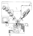
Fig. 1 is a side elevational view illustrating a tufting machine with cut pile hooks and loop pile loopers arranged in opposed, vertically spaced rows according to the present invention. -
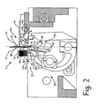
Fig. 2 is a side elevational view illustrating the engagement of the cut pile hooks and loop pile loopers with their associated needles in the tufting machine ofFig. 1 . -
Fig. 3 is a schematic illustration of the movement of the loop pile loopers and cut pile hooks between one another into engagement with the opposed rows of needles according to the present invention. -
Fig. 4A is a schematic illustration showing the movement of the loop pile loopers and cut/loop loopers or hooks between one another into engagement with the opposed rows of needles according to another possible embodiment of the present invention. -
Fig. 4B is a schematic illustration showing an additional alternative embodiment of the present invention. -
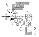
Fig. 5A is a side elevational view of a tufting machine incorporating another alternative embodiment of the present invention with cut pile hooks and loop pile loopers being arranged in opposed, vertically spaced rows in alignment with the needles of an inline needle bar. -
Fig. 5B is a side elevational view illustrating the engagement of the cut pile hooks and loop pile loopers through their associated needles in the tufting machine ofFig. 5A . -
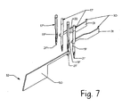
Fig. 6 is a schematic illustration of the engagement of the inline needles by their respective loop pile loopers and cut pile hooks. -
Fig. 7 is a schematic illustration showing the engagement of the inline needles of the tufting machines ofFigs. 5A and5B with their respective loop pile loopers and cut pile hooks. - Referring now in greater detail to the drawings in which like numerals indicate like parts throughout the several views, the present invention generally relates to a method and system for forming tufted fabrics having loop pile and cut pile tufts of synthetic grass filaments or yarns formed therein for forming various artificial/synthetic grass or turf products. As illustrated in
Fig. 1 , a tufting machine T utilizing the present invention generally will include atufting zone 10 through which abacking material 11 is fed into a feed direction, generally indicated byarrow 12 for the introduction of yarns (shown by dashed lines 13) into the backing material. - As indicated in
Fig. 1 , the tufting machine T generally will comprise a tufting machine such as disclosed inU.S. Patent Nos. 5,979,344 ,7,096,806 and/or7,359,761 ;
The tufting machine T generally will include aframe 5 on which is supported a machine drive, including a main drive shaft that reciprocally drives one or more reciprocating needle bars, 6A/6B each carrying a row of spacedneedles tufting zone 10 through which thebacking material 11 is fed by upstream and downstream backing rolls 7. While twoneedle bars 6A/6B are shown in the present embodiment, it will also be possible to utilize a single needle bar with in-line or staggered rows of needles as illustrated inFigs. 5A-7 and discussed below. A series of yarns, indicated by 13, are fed from one or more yarn feed mechanisms or devices 8 through pairs ofpuller rolls 9A and 9B to each of theneedles yarns 13 to the needles as the needles penetrate thebacking 11 and are engaged by gaugingelement assembly 25 of the tufting machine in order to form varying height loop and/or cut pile tufts of yarns within the backing material as indicated inFigs. 1-2 . - The
yarns 13 used to form the tufted turf fabric according to the present invention generally are synthetic grass filaments or yarns as commonly used for such turf fabrics. The yarns generally are fed to theneedles 17/18 from one or more yarn feed mechanisms 8 or sources and are inserted into thebacking material 11 to formloop pile tufts 14 and cutpile tufts 16, respectively, in the backing material. The yarn feed mechanism(s) can include scroll, roll, servo-scroll, single-end yarn feed, double-end yarn feed and/or other types of pattern and non-pattern yarn feed devices, such as an Infinity ™, Infinity IIE™ or Yarntronics™ yarn feed system or mechanism as manufactured by Card-Monroe Corp. for controlling feeding of the yarns to form various pattern effects in the finished tufted turf fabrics. - As indicated in
Figs. 1-3 , the tufting machine generally will include two spaced rows ofneedles needle Figs. 1-2 for clarity. The first or forwardmost/upstream row ofneedles 17 generally can comprise cut pile needles for inserting yarns for forming cut pile tufts into thebacking 11, while the second or rear row ofneedles 18 can comprise loop pile needles for inserting yarns for forming loop pile tufts into thebacking material 11 as show inFig. 1 . Eachneedle portion 19 adjacent their lower end orpoint 21 and achannel 22 along which ayarn 13 is received. The needles can be mounted in transversely spaced series along a single needle bar or along a pair of reciprocatingneedle bars 6A 6B that are driven by the operation of the main shaft of the tufting machine so as to move the needles through their reciprocating path into and out of thebacking material 11 for delivering theyarns 13 thereto. The needle bar or bars further can be dual shiftable needle bars shifted by a shift mechanism (not shown), such as an electric, hydraulic or servo-motor controlled shifter. - Additionally, as shown in
Figs. 1 - 2 , the needles of each row generally are vertically spaced with respect to each other, with the points of the needles of the first or upstream row ofneedles 17 located at a first elevation so as to project or extend to a first penetration depth or elevation that generally is below thepoints 21 of theneedles 18 of the second row of needles by a pre-set or predetermined vertical spacing. Theneedles 18 of the second rows of needles are mounted at a second elevation or level that generally is different from the first elevation of the first row ofneedles 17 so as to penetrate the backing to a second penetration depth that is at a second elevation or level that generally is different from the first elevation of the first row ofneedles 17 so that their points penetrate the backing at a different penetration depth with respect toneedles 17. Theneedles 17 can be of an increased length relative to theneedles 18 to help provide the desired spacing and penetration depth differences through the backing material for each needle stroke. Alternatively, theneedles Fig. 1 ) of the tufting machine to help avoid excess yarn bunching or being caught above the backing material. - Mounted beneath the
tufting zone 10 is a gaugingelement assembly 25, which can include a series of loopers, hooks, level cut loop looper, etc., and/or combinations thereof. In the presently illustrated embodiment, alooper assembly 30 is illustrated inFig. 1 on one side of the tufting zone. Thelooper assembly 30 generally includes a series of loop pileloopers 31 mounted in spaced series beneath the cut pile needles 17 at an elevation approximately corresponding to the second penetration depth of theneedles 18, arranged along an upstream or first side of atufting zone 10, and facing in thefeed direction 12 of thebacking material 11, and a series of transversely spaced cutpile hook assemblies 32 positioned along the downstream side of the tufting zone, and facing in an opposite direction from the loopers. The cut pile hook assemblies additionally are located at an elevation generally corresponding to the first penetration depth of theneedles 17, facing in an opposite direction from theloopers 31. The cut pile hook assemblies also will be located at an elevation generally corresponding to the first penetration depth of theneedles 17, arranged below the loop pile needles 18 and spaced vertically from the loop pile loopers by a predetermined spacing or distance. It will be understood by those skilled in the art that while only a single loop pile looper and cut pile hook assembly has been illustrated in the drawings for clarity, in practice, a number of loop pile loopers and cut pile hook assemblies will be provided in spaced series extending across the width of the tufting machine, with the number of loopers and cut pile hook assemblies being dependant upon the size of the tufting machine and number of needles thereof. - The system and method of forming artificial/synthetic sports grass or turf fabrics according to the present invention generally can utilize a "Velv-a-Loop" or other, similar tufting machine configuration such as indicated in
Fig. 4B , and preferably a Velv-a-Loop cross-over tufting zone configuration, as shown in the drawings such as inFigs. 1-2 , with free lengths of yarns fed from the yarn feed device(s) being controlled to accommodate the engagement and pulling of yarns from the needles by the corresponding loopers/hooks without excess yarns being accumulated above the backing material. Additionally, other systems such as level cut loop looper arrangements with air cylinder driven clips and other cross over arrangements can be used, such as shown inU.S. Patent No. 6,834,602 , the disclosure of which is incorporated herein by-reference as if set forth in its entirety. - As shown in
Fig. 3 , theloopers 31 are spaced transversely apart so as to definegaps 33 therebetween, while the cut pile hook assemblies are transversely spaced and definegaps 34 therebetween. The loop pile loopers are aligned with thegaps 34 between each of the cut pile hook assemblies. Conversely, the cutpile hook assemblies 32 are each aligned with thegaps 33 between theloopers 31. Similarly, the cut pile needles 17 will be positioned so as to travel through thegaps 33 between the loopers, while the loop pile needles 18 are positioned to reciprocate through thegaps 34 between the cutpile hook assemblies 32. In operation, the loopers and cut pile hook assemblies generally will pass between gaps defined between each of the cut pile and loop pile needles, respectively, in an intermeshing type of movement to engage their respective needles on the opposite side of the tufting zone as indicated inFig. 2 . - As illustrated in
Fig. 1 , eachloop pile looper 31 of thelooper assembly 30 generally includes ashank portion 41 that is mounted in a holder or block 42; and a forward body orthroat portion 43 that terminates in a tapered bill orforward end 44. During operation of the tufting machine, the loop pile loopers are rocked toward their respective needles as indicated byarrow 46 so that thebill portion 44 of eachloop pile looper 31 passes into the gap 34 (Fig. 3 ) between an opposed pair of cutpile hook assemblies 32 and engages thetakeoff portion 19 of its associatedloop pile needle 18, so as to pick up and pull a loop of yarn away from theloop pile needle 18. As eachlooper 31 is reciprocated rearwardly in the direction of arrow 46' and the loop pile needles 18 are reciprocated vertically back to their initial, raised position above the backing material, the loopers pick up and pull theyarns 13 away from theneedles 18. As a result, a series of loops of yarns will be formed along the bill portion of each looper for forming theloop pile tufts 14 in the backing material. - As illustrated in
Figs 1 and3 , each of the cutpile hook assemblies 32 comprises acut pile hook 50 that includes ashank 51 portion mounted within a holder or support 52 (Fig. 1 ) that carries the hook about a reciprocal motion indicated byarrows 53 and 53', toward and away from engagement with acut pile needle 17 as illustrated inFigs. 1 and2 . The hooks 50 (Figs. 1 and 3A) each further include abody portion 54 that extends upwardly and away from the shank, and atapered throat portion 56 that terminates in a hooked forward ordistal end 57 and can be level as well as unleveled. The hooks each further include a pickup side 58 (Fig. 3 ) that generally is of an opposite hand to the take off or pickup of the cut pile needles 17. In similar fashion to the loopers 31 (Figs. 1 - 2 ), as the hooks are reciprocated toward and away from their associated cut pile needles 17 in the direction ofarrow 53, their barbedfront portions 57 pass between adjacent loop pileloopers 31 and engage thetakeoff portion 19 of an associatedcut pile needle 17 on the opposite side of thetufting zone 10, as theneedles 17 are reciprocated to their lowered, engaging position, penetrating in the backing material. As the hooked or barbedfront portions 57 of thehooks 50 engagetakeoff portions 19 of their associatedneedles 17 and pick up and pull the yarns away from the cut pile needles 17, the needles are turned or reciprocated upwardly and thehooks 50 are moved in the direction of arrow 53'. As a result, a series of loops of yarn are formed along thethroat portions 56 of thehooks 50. - As generally illustrated in
Figs. 1 and2 , the cutpile hook assemblies 32 generally are spaced vertically below theloop pile loopers 31 by a distance that generally corresponds approximately to the vertical spacing of thefront needles 17 with respect to therear needles 18 of the tufting machine. This spacing generally can vary with the pile height of the loop and cut piles being formed, as well as upon the differences between the loop and cut pile tufts to be formed in the resultant turf fabric. For example, for a pile height of 7,6 - 15,2cm (3 - 6 inches), a spacing of approximately 6,35 - 10,2 cm (2.5 - 4 inches) can be used, depending upon the desired pile height of the resultant tufted fabric, although greater or lesser spacings between the cut pile hooks and the loop pile loopers also can be used as needed. The vertical spacing or elevation of the respective loopers and cut pile hooks further can be varied depending upon the gauge or spacing between the tufts of yarns being formed so as to enable tufts of yarn being formed in the tufted turf fabric. Such closer spacing of the cut and loop pile tufts can provide more support to the cut pile tufts of the tuft fabric, which in turn can provide increased or enhanced support with less fill-in of particulate material being required. - Alternatively, the cut pile hooks and loop pile loopers can be positioned with their
throats 56/43 at substantially the same depth or elevation. In such an arrangement, the cut pile hooks and/or loop pile loopers generally will be positioned at the lowest level for the deepest pile height tufts being formed. Once the loops of yarns are released from the loop pile loopers, the yarn feed system or mechanism can be controlled to pull back or back-rob the yarns to establish the desired pile height differential, for example, pulling back yarn from the released loop pile loopers by as much as 50% or more to achieve the desired pile height differential. The cut pile hooks and loop pile loopers further can be arranged to pass between each other or to simply engage their respective needles without reaching through the gaps between the opposed cut pile hooks or loop pile loopers, respectively. Still further, the cut pile hooks and loopers can be arranged or spaced so as to engage selected ones of theneedles 17/18, for example, having the loopers engage only a portion of theneedles 18, with the cut pile hooks engaging the rest, or with the cut pile hooks engaging only selectedneedles 17 while the loopers engage the rest, depending on the density and other features needed or desired for the artificial/synthetic grass or turf product being formed. - As further illustrated in
Figs. 1 - 2 , each cutpile hook assembly 32 further includes aknife assembly 61 that is mounted adjacent thethroat portion 56 of its associatedcut pile hook 50. Eachknife assembly 61 includes a cutting blade orknife 62 mounted in a holder 63 (Fig. 1 ) and having a cuttingedge 64. Each of thecutting blades 62 are reciprocated about a cutting path along thethroat portion 56 of its associatedcut pile hook 50, so as to engage and sever the loops of yarn formed along the throat portion of each cut pile hook in order to form thecut pile tufts 16 in thebacking material 11. - The knife can be of the same "hand" cutting as the hook, i.e., a right hand cutting blade for a right hand takeoff hook, or a left hand cutting blade for a left hand takeoff hook, and generally will be positioned on the opposite side of the takeoff or pickup region of the looper. Alternatively, as illustrated in
Fig. 3 , with the cutpile hook assembly 32 of the present invention, theknives 62 are of an opposite hand cutting to the pickup of their associatedhooks 50; for example, if the hook is a left hand pickup hook, a right hand cutting blade or knife is used, and conversely, for a hook having a right hand pickup hook, a left hand cutting knife will be used. Theknives 62 further are mounted along the pickup side of their hooks as indicated inFig. 3 . As a result, the knives are further aligned with, and thus are on the same side of the hooks as their respective cut pile needles as the needles are engaged by their associated hooks, instead of the needles being positioned on the opposite side of the hooks from the knives. In addition, a J-cut chamfer can be formed on the opposite side of eachhook 50 from itspickup side 58. - As the loopers and hooks 31/50 of the looper and
hook assemblies 30 and 32 (Fig. 1 ) are reciprocated in the direction ofarrows cut pile tufts 16. At the same time, the loops of yarn held on the bills of the loop pile loopers are simply pulled off the loopers as the backing material is moved along its path oftravel 12, leaving theloop pile tufts 14 of yarn in thebacking material 11, as shown inFig. 1 . Thus, the backing fabric will have cut pile and loop pile tufts of yarns in a single pass through the tufting machine formed therein. - In a further alternative embodiment of the invention, as indicated in
Fig. 4A , a series of cut/loop loopers or hooks 101 can be substituted for the cut pile hooks positioned along the downstream side of the tufting machine opposite theloop pile loopers 31 for forming the cut pile tufts. As shown inFig. 4A , theloop pile loopers 31 are spaced from each other so as to definegaps 33 therebetween, while the cut/loop loopers or hooks 101 are spaced transversely so as definegaps 102 therebetween. The loop pileloopers 31 are aligned with thegaps 102 between each of the cut/looper or hooks, while the cut/loop loopers or hooks are each aligned with agap 33 formed between each of theloop pile loopers 31. In addition, the cut pile needles 17 positioned along the upstream side of the tufting zone will pass through thegap 33 between theloop pile loopers 31 for engagement therewith by the cut/loop loopers or hooks, while the loop pile needles 18, positioned along the downstream side of the tufting zone, will pass through thegaps 102 between each of the cut/loop loopers or hooks for engagement by thebill portions 44 of theloop pile loopers 31 as the loop pile loopers are rocked forwardly during a stroke or cycle of the tufting machine. - Each cut/loop looper or hook 101 (
Fig. 4A ) generally includes abody 103 with a rear orshank portion 104 mounted within a holder that carries the cut/loop looper or hook about a reciprocating motion into and out of engagement with acut pile needle 17, and further includes a bill orforward portion 108 that terminates in a pointed or tapered front end orforward end 109. Aclip 111 generally is attached to theshank portion 104 of each cut/loop looper orhook 101. Eachclip 111 typically is formed from a metal material such as spring steel or other similar, resilient material that can be attached to itslooper body 103 by a fastener such as a rivet, bolt, welding or other similar fastening mechanisms as will be understood in the art. The clip includes a forwardly extending front body section having an engagingportion 114 that bears against theforward end 109 of its attached cut/loop looper orhook 101, and terminates in a front orproximal end 116. Theforward end 116 is angled slightly outwardly, as is shown inFig. 4A , such that as theforward end 109 of each cut/loop looper or hook strikes its respective cut pileneedle 17, the clip can be urged away from the bill portion of the cut/loop looper or hook to allow the passage of the needle therebetween as the yarn is picked up or taken off itsneedle 17 to form a loop of yarn along thebill 108 of the cut/loop looper or hook. As the cut pile needles 17 are retracted from engagement with their cut/loop loopers or hooks, the clips will be returned to their tight bearing engagement with the forward end or bill portions of their respective cut/loop loopers or hooks so as to retain the loops of yarn formed therealong for cutting by their associatedknives 62. - Another alternative embodiment of the invention for forming synthetic or artificial grass/turf products without necessarily requiring multiple passes of the product through a tufting machine is schematically illustrated in
Fig. 4B . In this embodiment, thehooks 50 of the cutpile hook assemblies 32 are located along the downstream side of the tufting zone, aligned with a first or downstream series or group ofneedles 18 at an elevation corresponding to a first penetration depth to which thedownstream needles 18 extend or penetrate through thebacking material 11. Theloopers 31 oflooper assemblies 30 are generally located on the upstream side of the tufting zone T, below and aligned with theneedles 17 of a second or upstream row of needles. AsFig. 4B indicates, theloopers 31 are arranged at an elevation substantially corresponding to a second penetration depth to which theupstream needles 17 extend or penetrate through the backing material. During a tufting operation, thehooks 50 andloopers 31 will engage theneedles Fig. 4B . The loopers and hooks will pick and pull loops of yarns from their needles, with the loops formed by the hooks being cut byknives 62 to form cutpile tufts 16 interspersed with theloop pile tufts 14 and having a greater length or pile height. - in still another alternative embodiment of the invention, shown in
Figs. 5A - 7 , the tufting machine T can include a single inline needle bar, as noted above, having first and second groups ofneedles points 21' and 21" extend or project to different elevations or penetration depths. Theneedles Figs. 5A-6 , or can be staggered along the needle bar, and generally will be engaged from opposite sides by cut pile hooks 50 and loop pileloopers 31 as indicated inFigs. 6 and7 . The needle bar also can be shiftable by a shift mechanism (not shown), or can be controlled so as to be oscillated or moved in a positive stitch placement type fashion, while running substantially straight rows or tufts, to avoid corn-row type effects in the finished tufted tuft fabrics. As further indicated inFigs. 5A - 7 , the first and second groups or series ofinline needles needles 17', as shown inFig. 7 . Alternatively, theneedles needles 17'/17" are different elevations, or can include level elevation needles; hooks and loopers. - As illustrated in
Figs. 6 and7 , the take-off areas orportions needle respective needles Fig. 7 , for each pair ofneedles portions 19'/19" will be oriented so as to face in opposite directions, which can enable closer spacings or gauges for the cut and loop pile tufts of yarns being formed. The hooks and loopers further can be arranged so as to engage alternate ones of the needles, for example, the loopers can engage every even needle 17' and the hooks everyodd needle 17." Alternatively, the loopers and hooks can be arranged so as to engage selectedneedles 17' and/or 17", such as having the loopers engage every third, fourth, etc., needle while the hooks engage the remaining needles, or the hooks can be arranged to engage every third, fourth, etc., needle, for forming more or fewer cut/loop pile tufts as needed to achieve a desired density and/or other pattern effects in the resultant artificial turf/grass product. Other alternative arrangements also can be utilized as needed or desired. - In operation, as indicated in
Figs. 5B-7 , theloopers 31 and hooks 50 will move toward each other, into an intermeshing arrangement to engage the first and second groups or series ofneedles Figs. 6 and7 for forming the cut end loop pile tufts having different lengths or pile heights. It further will be understood that there additionally can be other alternative arrangements of loop pile loopers and cut pile hooks that can be utilized with the inline needle bar(s), including the use of level cut loopers or hooks, or the use of loop pile loopers or cut pile hooks on both sides of the tufting zone to form level cut loop pile tufts, all loop pile tufts or all cut pile tufts. - The artificial/synthetic sports grass or turf fabric formed according to the present invention additionally can be formed with two levels of cut pile or loop pile tufts, while generally being run in a single pass through the tufting machine, rather than requiring multiple tufting passes and overtufting of the tufted fabric. In such a system or arrangement, two rows of cut pile hooks or two rows of loop pile loopers can be provided, with a first or upstream row of cut pile hooks generally being vertically spaced from the downstream or second row of cut pile hooks/loop pile loopers. Additionally, two different length needles typically can be used, although it is also possible to use needles of substantially the same length mounted on separate needle bars, with the needles being staggered in terms of their elevation or depth to enable different penetration levels. Still further, the needles can be mounted on a single needle bar in a staggered needle configuration or spacing, or with the needles arranged in-line along the needle bar, and the stroke of the needle bar can be based upon the stroke or penetration depth required for the longest needle to penetrate and be engaged by its corresponding cut pile hooks. Additionally, the cut pile hooks can be spaced in pairs to enable sufficient spacing between each of the pairs for penetration of the needles therebetween the slotting of the needle plates without undue weakening of the needle plates in order to ensure accurate engagement and pickup of the loops of yarn on the needles as the hooks or loopers pass therebetween, especially as the gauges for the tufting machine are narrowed.
- Still further, it also will be understood that in addition to various pattern mechanisms or systems such as mechanisms or devices to control the feeding of the yarns to the needles and shifting of the needle bar(s) to prevent excess yarn from being pulled and left on top of the backing material, systems/attachments for forming various pattern effects, such as sculptured or textured pile effects, or the formation of logos or other designs using various different colors and shades of yarn, including backing feed shifters and other pattern systems, also can be used. For example, the present system can utilize a backing control system such as Card-Monroe Corp.'s Virtual Weave ™ to control the shifting of the backing material. Such a backing feed control further can be used in conjunction with shifting needle bars, as well as a pattern yarn feed mechanisms to provide further enhanced patterning and formation of desired visual effects. Still further, positive stitch placement also can be utilized, whereby the needle bar(s) are incrementally shifted laterally back and forth across the backing material as they are reciprocated to form tufts in the backing material, in addition to being shifted in steps for pattern formation, in order to tighten and substantially eliminate rowing effects for the tufts so as to create a stronger, more natural looking and denser tufted feel. This can help reduce the amount of fill needed for supporting the tufts, as well as providing better control of the yarn feed to allow for lower weights to the yarns to be used and reduced pile heights of the tufts in order to get the desired density required for enhanced player comfort, support, and ball bounce.
- Accordingly, utilizing the principles of the present invention, artificial/synthetic sports grass or turf fabrics or products can be formed utilizing a single pass tufting operation or production, without requiring over-tufting, whereby the backing material is run in a first pass through the first tufting machine (i.e., loop pile machine) and then the initially tufted material taken to and run through a second tufting machine in a second pass or operation. In addition, loop pile tufts can be formed with sufficient density, height, and spacing, to provide enhanced support for the cut pile tufts that generally are of higher pile heights, with the loop pile tufts being formed by operation of the loopers reaching through the front row of needles to the rear row of needles for making tufts that will substantially eliminate sew through of the loop pile tufts by the cut pile needles. Still further, the cut pile tufts can be formed by the hooks reaching through the rear row of needles to the front rows of needles to form the cut pile tufts in the fabric, without further requiring over-sewing of the loop pile tufts.
- As a result, the finished tufted turf fabric can be formed with enhanced rigidity, with the loop pile tufts supporting the cut pile tufts so as to make such tufts in the resultant turf fabric stronger and more resistant to bending over due to loads such as crushing forces during play. Still further, the use of various pattern devices as discussed above can enable variable pile heights for the cut and loop pile tufts so as to vary the characteristics of the tufted turf fabric to meet various desired standards for cushioning, support, ball roll, and ball bounce, all while helping to reduce the amount of fill with particulate matter required for support of the tufts, and further enable various designs or pattern effect to also be formed in the resultant tufted turf fabrics.
- The present invention further enables the passing of the loopers and hooks through the gaps defined therebetween with the incidents of previously sewn loops of yarn being engaged by the cut pile hooks during the production of finer or smaller gauge (i.e., 5/32 - 1/16 gauge) carpets being minimized, while still further enabling the stagger between the rows of needles to be reduced to as short as approximately 1,27 cm (1/2 inch) - approximately 0,625 cm (1/4 inch) or less without the knives engaging the previously sewn loops or otherwise engaging and interfering with the operation of the loopers. As a result, given the reduction in the stagger, the problems of side matching, i.e., matching of the left and right seam of a carpet, are minimized since the stagger can be reduced, which correspondingly reduces the stretching and/or necking of the backing material as the backing material passes passing through the tufting zone.
Claims (15)
- A tufting machine (T) for forming an artificial/synthetic sports turf, comprising:a first row of needles (17) positioned adjacent an upstream side of a tufting zone (10) of the tufting machine (T), each needle (17) having a pickup area (19) formed therealong and carrying a synthetic grass yarn (13) for introduction into a backing (11) moving through the tufting zone (10);a second row of needles (18) spaced transversely across the tufting zone (10) from said first row of needles (17), said second row of needles (18) each having a pickup area (19) and carrying synthetic grass yarns (13) for introduction into a the backing (11);a series of hooks (50) positioned for an engagement with said needles (17) of said first row of needles (17) to pickup the yarns (13) therefrom;a series of knives (62) each positioned along a pickup side (58) of one of said hooks (50) and adapted to engage the yarns (13) picked up by the hooks (50) for forming cut pile tufts (16) in the backing (11);characterized bya series of loopers (31) moveable between said needles (17) of said first row of needles (17) into engagement with said needles (18) of said second row of needles (18) so as to engage and pickup the yarns (13) therefrom to form the loop pile tufts (14) in the backing (11); andsaid series of hooks (50) positioned opposite said loopers (31) and at a different elevation from said loopers (31), said hooks (50) moveable between said needles (18) of said second row of needles (18) into engagement with said needles (17) of said first row of needles (17) to pickup the yarns (13) therefrom.
- The tufting machine (T) of claim 1 and wherein said knives (62) are of an opposite hand cutting to the pickup (58) of said hooks (50).
- The tufting machine (T) of claim 2 and wherein said knives (62) are right hand cut and said hooks (50) are left hand pickup.
- The tufting machine (T) of claim 2 and wherein said knives (62) are left hand cut and said hooks (50) are right hand pickup.
- The tufting machine (T) of claim 2 and wherein said knives (62) are generally aligned with said needles (17) of said first row of needles (17).
- The tufting machine (T) of claim 1 and wherein said hooks (50) are located at an elevation corresponding to a first penetration depth of said needles of said first row of needles (17), and said loopers (31) are located at an elevation corresponding to a second penetration depth of said needles of said second row of needles (18) and pass between said needles of said first row of needles (17) to engage said second row of needles (18).
- The tufting machine (T) of claim 6 and wherein said first penetration depth extends to an elevation lower than said second penetration depth.
- The tufting machine (T) of claim 1, further comprising a pair of needle bars (6A/6B), and wherein said first row of needles (17) are mounted to an upstream one of said needle bars (6B) and said needles of said second row of needles (18) are mounted to a downstream one of said needle bars (6B).
- The tufting machine (T) of claim 1 and wherein said needles of said first and second rows of needles (17.18) are mounted in-line along a single needle bar.
- A method of forming an artificial/synthetic turf, comprising:moving a backing (11) along a path of travel through a tufting zone (10);engaging the backing (11) with a first row of spaced needles (17) carrying a plurality of yarns (13) through the backing (11) to a first penetration depth;engaging the backing (11) with a second row of spaced needles (18), transversely spaced from the first row of needles (17) across the tufting zone (10) and carrying a second plurality of yarns (13) through the backing (11) to a second penetration depth;characterized by:moving a plurality of hooks (50) across the tufting zone (10) between the needles (18) of the second row of needles (18) and into engagement with the yarns (13) carried by the needles (17) of the first row of needles (17) through the backing (11) to a first penetration depth;reciprocating a series of knives (62) into contact with the yarns (13) engaged by the hooks (50) to form cut pile tufts (16) in the backing (11); andmoving a series of loopers (31) across the tufting zone (10) between the needles (17) of the first row of needles (17) and into engagement with the yarns (13) carried by the needles (18) of the second row of needles (18) through the backing (11) to the second penetration depth to form the loop pile tufts (14) in the backing (11).
- The method of claim 10 and wherein providing the knives (62) along the pickup side of each hook (50) comprises aligning each knife (62) with one of the needles of the needle of the first row of needles (17).
- The method of claim 10 and further comprising cutting a series of yarns (13) engaged on the hooks (50) with the knives (62) to form the cut pile tufts (16).
- The method of claim 10 and further comprising shifting the needles (17, 18) laterally with respect to the backing (11).
- The method of claim 10 and wherein the first penetration depth extends to a lower elevation than the second penetration depth.
- The method of claim 10 and further comprising locating the hooks (50) at an elevation approximately corresponding to the first penetration depth and locating the loopers (31) at an elevation corresponding to the second penetration depth.
Applications Claiming Priority (4)
| Application Number | Priority Date | Filing Date | Title |
|---|---|---|---|
| US95784207P | 2007-08-24 | 2007-08-24 | |
| US97608907P | 2007-09-28 | 2007-09-28 | |
| US98154607P | 2007-10-22 | 2007-10-22 | |
| PCT/US2008/074222 WO2009029581A1 (en) | 2007-08-24 | 2008-08-25 | System and method for forming artificial/synthetic sports turf fabrics |
Publications (2)
| Publication Number | Publication Date |
|---|---|
| EP2201165A1 EP2201165A1 (en) | 2010-06-30 |
| EP2201165B1 true EP2201165B1 (en) | 2011-06-01 |
Family
ID=40202970
Family Applications (1)
| Application Number | Title | Priority Date | Filing Date |
|---|---|---|---|
| EP20080828602 Not-in-force EP2201165B1 (en) | 2007-08-24 | 2008-08-25 | System and method for forming artificial/synthetic sports turf fabrics |
Country Status (5)
| Country | Link |
|---|---|
| US (1) | US7946233B2 (en) |
| EP (1) | EP2201165B1 (en) |
| CN (1) | CN101835931B (en) |
| AT (1) | ATE511564T1 (en) |
| WO (1) | WO2009029581A1 (en) |
Families Citing this family (24)
| Publication number | Priority date | Publication date | Assignee | Title |
|---|---|---|---|---|
| SI1579076T1 (en) * | 2002-12-19 | 2011-09-30 | Greenfields B V | Artificial turf mat and method for manufacturing thereof |
| US8186454B2 (en) * | 2004-08-20 | 2012-05-29 | Sdg, Llc | Apparatus and method for electrocrushing rock |
| BE1017560A3 (en) * | 2007-04-18 | 2008-12-02 | Wiele Michel Van De Nv | WOVEN ART GRASS MAT WITH FINE POOL DIVISION. |
| NL1036870C2 (en) * | 2009-04-17 | 2010-10-19 | Ten Cate Itex B V | DEVICE FOR MANUFACTURING A FIBER MAT BY WEAVING. |
| US9051672B2 (en) * | 2010-12-17 | 2015-06-09 | John H. Bearden | Tufting machine for producing a precise graphic design |
| US8347800B1 (en) | 2011-07-26 | 2013-01-08 | Interface, Inc. | Methods for tufting a carpet product |
| CN102697199A (en) * | 2012-06-25 | 2012-10-03 | 太仓协大申泰羊毛衫有限公司 | Method for manufacturing woolen sweater with tufting |
| US8997668B1 (en) * | 2013-02-06 | 2015-04-07 | Robert S. Weiner | Overtufting station |
| US8915202B2 (en) | 2013-03-01 | 2014-12-23 | Card-Monroe Corp. | Looper module for tufting chain-stitch fabrics |
| EP2997187B1 (en) | 2013-05-13 | 2018-08-29 | Card-Monroe Corporation | System and method for forming patterned artificial/synthetic sports turf fabrics |
| US20150147492A1 (en) * | 2013-11-26 | 2015-05-28 | German Aello Garcia | Process of Manufacturing Artificial Turf |
| US9909254B2 (en) | 2013-12-05 | 2018-03-06 | Card-Monroe Corp. | System and method for formation of woven style tufted cut/loop fabrics |
| US9476152B2 (en) * | 2014-01-28 | 2016-10-25 | Card-Monroe Corp. | Tufting system with mini-staggered needles |
| US9290874B2 (en) | 2014-04-09 | 2016-03-22 | Card-Monroe Corp. | Backing material shifter for tufting machine |
| US20160032510A1 (en) * | 2014-08-01 | 2016-02-04 | Card-Monroe Corp. | Method and apparatus for forming variable cut and/or loop pile tufts over level cut loop tufts |
| EP3277875A4 (en) * | 2015-04-01 | 2018-11-07 | Card-Monroe Corporation | Tufted fabric with pile height differential |
| US9657419B2 (en) | 2015-10-01 | 2017-05-23 | Card-Monroe Corp. | System and method for tufting sculptured and multiple pile height patterned articles |
| US11193225B2 (en) | 2016-03-17 | 2021-12-07 | Card-Monroe Corp. | Tufting machine and method of tufting |
| US10233578B2 (en) * | 2016-03-17 | 2019-03-19 | Card-Monroe Corp. | Tufting machine and method of tufting |
| CN112189068A (en) * | 2018-05-09 | 2021-01-05 | 马尔项目公司 | Infill material for synthetic turfs and synthetic turfs obtained therefrom |
| CN110080061B (en) * | 2019-05-21 | 2022-01-11 | 常州市首佳人造草坪科技有限公司 | Manufacturing method of high-low grass filament warp-knitted artificial lawn |
| KR102167720B1 (en) * | 2019-09-17 | 2020-10-19 | 주식회사 세주 | Planting device for artificial turf pile |
| CN112981760B (en) * | 2021-01-23 | 2022-05-10 | 山东容润丰地毯有限公司 | Asynchronous needling tufting machine for hard filaments and soft filaments |
| US11585029B2 (en) | 2021-02-16 | 2023-02-21 | Card-Monroe Corp. | Tufting maching and method of tufting |
Family Cites Families (77)
| Publication number | Priority date | Publication date | Assignee | Title |
|---|---|---|---|---|
| US2990792A (en) * | 1958-03-12 | 1961-07-04 | Lees & Sons Co James | Industrial apparatus |
| US3203379A (en) * | 1961-08-07 | 1965-08-31 | George D Dedmon | Tufting machine with retractable loopers |
| US3084645A (en) * | 1962-07-26 | 1963-04-09 | Singer Cobble Inc | Method and apparatus for tufting cut pile and loop pile in the same row of stitching |
| US3577943A (en) * | 1969-04-03 | 1971-05-11 | Singer Co | Dense pile tufting machines |
| US3618542A (en) * | 1970-03-20 | 1971-11-09 | Singer Co | Multineedle unit |
| US3662697A (en) * | 1970-10-09 | 1972-05-16 | William Erby Passons | Method and apparatus for tufting uniform cut pile |
| US4048930A (en) * | 1971-03-16 | 1977-09-20 | Card & Co. Inc. | Method and apparatus for forming J-tuft pile |
| US3709173A (en) * | 1971-07-01 | 1973-01-09 | Jorges Carpet Mills Inc | Modular tufting unit |
| US3835797A (en) * | 1971-11-11 | 1974-09-17 | A Franks | Pattern control for tufting machines |
| US3780678A (en) * | 1972-01-10 | 1973-12-25 | Doering Milliken Research Corp | Process and apparatus for the production of tufted pile fabrics |
| US3908570A (en) * | 1972-05-26 | 1975-09-30 | Fieldcrest Mills Inc | Patterned tufted fabrics and method of making same |
| US3847098A (en) * | 1973-07-23 | 1974-11-12 | Card & Co Inc | Yarn feed module for tufting machine |
| US3919953A (en) * | 1974-10-16 | 1975-11-18 | Card & Co Inc | Apparatus for tufting spaced rows of loop pile and cut pile |
| US4103629A (en) * | 1977-06-21 | 1978-08-01 | Card & Co., Inc. | Looper apparatus for forming cut pile and loop pile in the same row of stitching in a narrow gauge tufting machine |
| GB2002040B (en) | 1977-08-05 | 1982-01-06 | Pickering Ltd E | Tufting machines |
| US4134347A (en) * | 1978-01-31 | 1979-01-16 | Spencer Wright Industries, Inc. | Method and apparatus for tufting even level cut pile and loop pile in the same row of stitching |
| US4226196A (en) * | 1978-04-14 | 1980-10-07 | Firth Carpets Limited | Tufting machines |
| US4155319A (en) * | 1978-06-08 | 1979-05-22 | Tuftco Corporation | Looper apparatus for forming cut pile and loop pile in the same row of stitching |
| US4185569A (en) * | 1979-01-29 | 1980-01-29 | Spencer Wright Industries, Inc. | Method and apparatus for tufting even level cut pile and loop pile in the same row of stitching |
| US4217837A (en) * | 1979-04-30 | 1980-08-19 | Tuftco Corporation | Fine gauge looper apparatus for in-line tufting machine |
| MX150994A (en) | 1979-05-30 | 1984-09-06 | Hunter Douglas International | IMPROVEMENTS IN TILT ROLL ADAPTED TO MOVE ON A ROTATING TILT ROD OF A VENETIAN BLIND |
| US4366761A (en) * | 1980-12-02 | 1983-01-04 | Tuftco Corporation | Dual shiftable needle bars for tufting machine |
| US4398479A (en) * | 1981-06-26 | 1983-08-16 | Fieldcrest Mills, Inc. | Tufting machine with shiftable and indexing needle bars and method of tufting |
| US4419944A (en) * | 1981-11-09 | 1983-12-13 | Passons William E | Multiple stroke looper mechanism for stitching machine |
| US4353317A (en) * | 1982-02-04 | 1982-10-12 | Spencer Wright Industries, Inc. | Method and apparatus for tufting high and low pile in the same row of stitching |
| DE3303206C2 (en) | 1982-02-12 | 1985-07-04 | Haniisuchiiru Co. Ltd., Osaka | Tufting machine |
| US4440102A (en) * | 1983-05-19 | 1984-04-03 | Card Roy T | Tufting machine and method of tufting for producing multiple rows of tufts with single lengths of yarn |
| US4619212A (en) * | 1983-05-19 | 1986-10-28 | Card Roy T | Tufting machine and method of tufting for producing multiple rows of tufts with single lengths of yarn |
| US4630558A (en) * | 1983-05-19 | 1986-12-23 | Card Roy T | Tufting machine and method of tufting for producing multiple rows of tufts with single lengths of yarn |
| US4557209A (en) * | 1984-07-13 | 1985-12-10 | Tuftco Corporation | Sculptured high-low cut pile tufting method and apparatus |
| US4557208A (en) * | 1984-09-24 | 1985-12-10 | Spencer Wright Industries, Inc. | Method and apparatus for tufting patterned fabric |
| GB8425937D0 (en) | 1984-10-13 | 1984-11-21 | Thomson Shepherd Carpets Ltd | Tufted patterned carpet |
| JPS63203861A (en) * | 1987-02-16 | 1988-08-23 | 株式会社 中川製作所 | Pile yarn feeder in tufting machine |
| US4754718A (en) * | 1987-06-16 | 1988-07-05 | Tuftco Corporation | Double needle bar tufting apparatus for the formation of loop pile and cut pile |
| US4903625A (en) * | 1988-01-12 | 1990-02-27 | Card-Monroe Corporation | Apparatus and method for producing a cut loop overlay of a loop pile base fabric in a single pass of the base fabric through the tufting machine |
| US4903624A (en) * | 1988-01-12 | 1990-02-27 | Card-Monroe Corporation | Cut loop over cut pile fabric and apparatus for and method of producing the same |
| US4836118A (en) * | 1988-01-12 | 1989-06-06 | Card-Monroe Corporation | Apparatus and method for producing a cut loop overlay of a loop pile base fabric in a single pass of the base fabric through the tufting machine |
| US4815403A (en) * | 1988-01-12 | 1989-03-28 | Card-Monroe Corporation | Cut loop over cut pile fabric and apparatus for and method of producing the same |
| US4800828A (en) * | 1988-02-01 | 1989-01-31 | Tuftco Corporation | Double needle bar loop pile tufting apparatus |
| JPH0515914Y2 (en) * | 1988-07-15 | 1993-04-26 | ||
| US4864846A (en) * | 1988-10-17 | 1989-09-12 | Western Atlas International, Inc. | Self-cleaning poppet valve for a core testing apparatus |
| US4864946A (en) | 1988-11-18 | 1989-09-12 | Tuftco Corporation | Yarn feed split roll apparatus for tufting machine |
| US5058518A (en) * | 1989-01-13 | 1991-10-22 | Card-Monroe Corporation | Method and apparatus for producing enhanced graphic appearances in a tufted product and a product produced therefrom |
| US4860674A (en) * | 1989-02-03 | 1989-08-29 | Spencer Wright Industries, Inc. | Tufting machine and method for producing level cut and loop pile |
| US5094178A (en) * | 1990-03-22 | 1992-03-10 | Tuftco Corporation | Method and apparatus for tufting accent yarns in patterned pile fabric |
| GB9014635D0 (en) | 1990-06-30 | 1990-08-22 | Cobble Blackburn Ltd | Improvements in tufting machines |
| US5224434A (en) * | 1991-02-11 | 1993-07-06 | Card Roy T | Method and apparatus for producing tufts from different yarns in longitudinal lines |
| US5295450A (en) * | 1992-05-01 | 1994-03-22 | Card-Monroe Corp. | Tufting machine with self-aligning gauging modules |
| US6228460B1 (en) * | 1993-06-01 | 2001-05-08 | Interface, Inc. | Tufted articles and related processes |
| US5575228A (en) * | 1993-08-25 | 1996-11-19 | Tuftco, Inc. | Variable gauge tufting apparatus |
| US5544605A (en) * | 1994-03-10 | 1996-08-13 | Tuftco Corporation | Auxiliary yarn feed module for tufting machine with pattern control yarn feed mechanism |
| GB2290560B (en) * | 1994-06-17 | 1998-12-30 | Cobble Blackburn Ltd | Improvements in or relating to tufting machines |
| US5743201A (en) * | 1995-01-23 | 1998-04-28 | Card-Monroe Corp. | Tufting machine pattern yarn feed mechanism |
| US5622126A (en) * | 1995-01-23 | 1997-04-22 | Card-Monroe Corporation | Tufting machine yarn feed mechanism |
| US6009818A (en) * | 1995-01-23 | 2000-01-04 | Card-Monroe Corp. | Tufting machine pattern yarn feed device |
| GB2331109B (en) * | 1995-05-31 | 1999-12-08 | Tuftco Corp | Improved fine gauge tufting machine |
| US6244203B1 (en) * | 1996-11-27 | 2001-06-12 | Tuftco Corp. | Independent servo motor controlled scroll-type pattern attachment for tufting machine and computerized design system |
| US6283053B1 (en) * | 1996-11-27 | 2001-09-04 | Tuftco Corporation | Independent single end servo motor driven scroll-type pattern attachment for tufting machine |
| GB9625881D0 (en) * | 1996-12-12 | 1997-01-29 | Cobble Blackburn Ltd | Improved yarn feed system for a tufting machine |
| US5983815A (en) * | 1997-03-11 | 1999-11-16 | Card-Monroe Corp. | Tufting machine with pattern yarn feed and distribution device |
| US5896821A (en) * | 1997-07-18 | 1999-04-27 | Card-Monroe Corp. | Tufting machine gauging element configuration |
| US6279497B1 (en) * | 1998-10-29 | 2001-08-28 | Tuftco Corporation | Method of manufacturing textured carpet patterns and improved tufting machine configuration |
| GB2357301A (en) * | 1999-12-16 | 2001-06-20 | Cobble Blackburn Ltd | Tufting machine with independent control of the needle bars |
| US6155187A (en) * | 2000-01-21 | 2000-12-05 | Spencer Wright Industries, Inc. | Tufting of level cut pile and loop pile in the same row of stitching |
| US6213036B1 (en) * | 2000-03-27 | 2001-04-10 | Spencer Wright Industries, Inc. | Tufting machine yarn feed pattern control |
| GB0028891D0 (en) * | 2000-11-27 | 2001-01-10 | Cobble Blackburn Ltd | A yarn feed for assembly for a tufting machine |
| GB2398791B (en) * | 2001-11-02 | 2004-10-13 | John Thomas Liddy | Improved block paving sand |
| US6807917B1 (en) * | 2002-07-03 | 2004-10-26 | Card-Monroe Corp. | Yarn feed system for tufting machines |
| US6834601B2 (en) * | 2002-07-03 | 2004-12-28 | Card-Monroe Corp. | Yarn feed system for tufting machines |
| US6758154B2 (en) * | 2002-07-05 | 2004-07-06 | Kendall Johnston | Tufting machine |
| US6550407B1 (en) * | 2002-08-23 | 2003-04-22 | Tuftco Corporation | Double end servo scroll pattern attachment for tufting machine |
| SI1579076T1 (en) * | 2002-12-19 | 2011-09-30 | Greenfields B V | Artificial turf mat and method for manufacturing thereof |
| US7007617B2 (en) * | 2003-11-26 | 2006-03-07 | Card-Monroe Corp. | Gate assembly for tufting machine |
| US6834602B1 (en) | 2004-01-20 | 2004-12-28 | Card-Monroe Corp. | Method and apparatus for forming cut and loop pile tufts |
| US7216598B1 (en) * | 2004-09-21 | 2007-05-15 | Card-Monroe Corp. | System and method for pre-tensioning backing material |
| ITMI20050037A1 (en) * | 2005-01-14 | 2006-07-15 | Italgreen S P A | CARPET IN PARTICULAR FOR SYNTHETIC HERBOSIAN COATS STRUCTURE OF SYNTHETIC HERBAL COAT INCLUDING THE CARPET AND METHOD AND MANUFACTURING EQUIPMENT FOR THE CARPET |
| US7490566B2 (en) * | 2007-03-02 | 2009-02-17 | Card-Monroe Corp. | Method and apparatus for forming variable loop pile over level cut loop pile tufts |
-
2008
- 2008-08-25 CN CN2008801129879A patent/CN101835931B/en not_active Expired - Fee Related
- 2008-08-25 EP EP20080828602 patent/EP2201165B1/en not_active Not-in-force
- 2008-08-25 AT AT08828602T patent/ATE511564T1/en not_active IP Right Cessation
- 2008-08-25 WO PCT/US2008/074222 patent/WO2009029581A1/en active Application Filing
- 2008-08-25 US US12/197,673 patent/US7946233B2/en active Active
Also Published As
| Publication number | Publication date |
|---|---|
| WO2009029581A1 (en) | 2009-03-05 |
| US7946233B2 (en) | 2011-05-24 |
| ATE511564T1 (en) | 2011-06-15 |
| CN101835931A (en) | 2010-09-15 |
| US20090050037A1 (en) | 2009-02-26 |
| EP2201165A1 (en) | 2010-06-30 |
| CN101835931B (en) | 2013-04-03 |
Similar Documents
| Publication | Publication Date | Title |
|---|---|---|
| EP2201165B1 (en) | System and method for forming artificial/synthetic sports turf fabrics | |
| US11214905B2 (en) | System and method for forming patterned artificial/synthetic sports turf fabrics | |
| US10995441B2 (en) | Yarn color placement system | |
| US10995442B2 (en) | Tufted fabric with pile height differential | |
| US7739970B2 (en) | Method and apparatus for forming variable loop pile over level cut loop pile tufts | |
| US6834602B1 (en) | Method and apparatus for forming cut and loop pile tufts | |
| EP3722478A1 (en) | System and method for tufting sculptured and multiple pile height patterned articles | |
| US20130180440A1 (en) | System and Method for Forming Artificial Turf Products with a Woven Appearance | |
| US20160032510A1 (en) | Method and apparatus for forming variable cut and/or loop pile tufts over level cut loop tufts | |
| US6279497B1 (en) | Method of manufacturing textured carpet patterns and improved tufting machine configuration | |
| US20020170477A1 (en) | Tufting needle assembly |
Legal Events
| Date | Code | Title | Description |
|---|---|---|---|
| PUAI | Public reference made under article 153(3) epc to a published international application that has entered the european phase |
Free format text: ORIGINAL CODE: 0009012 |
|
| 17P | Request for examination filed |
Effective date: 20100322 |
|
| AK | Designated contracting states |
Kind code of ref document: A1 Designated state(s): AT BE BG CH CY CZ DE DK EE ES FI FR GB GR HR HU IE IS IT LI LT LU LV MC MT NL NO PL PT RO SE SI SK TR |
|
| AX | Request for extension of the european patent |
Extension state: AL BA MK RS |
|
| DAX | Request for extension of the european patent (deleted) | ||
| RIN1 | Information on inventor provided before grant (corrected) |
Inventor name: GODFREY, CODY Inventor name: HALL, WILTON Inventor name: NEELY, ALLEN |
|
| GRAP | Despatch of communication of intention to grant a patent |
Free format text: ORIGINAL CODE: EPIDOSNIGR1 |
|
| GRAS | Grant fee paid |
Free format text: ORIGINAL CODE: EPIDOSNIGR3 |
|
| GRAA | (expected) grant |
Free format text: ORIGINAL CODE: 0009210 |
|
| AK | Designated contracting states |
Kind code of ref document: B1 Designated state(s): AT BE BG CH CY CZ DE DK EE ES FI FR GB GR HR HU IE IS IT LI LT LU LV MC MT NL NO PL PT RO SE SI SK TR |
|
| REG | Reference to a national code |
Ref country code: GB Ref legal event code: FG4D |
|
| REG | Reference to a national code |
Ref country code: CH Ref legal event code: EP |
|
| REG | Reference to a national code |
Ref country code: IE Ref legal event code: FG4D |
|
| REG | Reference to a national code |
Ref country code: DE Ref legal event code: R096 Ref document number: 602008007354 Country of ref document: DE Effective date: 20110714 |
|
| REG | Reference to a national code |
Ref country code: NL Ref legal event code: VDEP Effective date: 20110601 |
|
| PG25 | Lapsed in a contracting state [announced via postgrant information from national office to epo] |
Ref country code: HR Free format text: LAPSE BECAUSE OF FAILURE TO SUBMIT A TRANSLATION OF THE DESCRIPTION OR TO PAY THE FEE WITHIN THE PRESCRIBED TIME-LIMIT Effective date: 20110601 Ref country code: LT Free format text: LAPSE BECAUSE OF FAILURE TO SUBMIT A TRANSLATION OF THE DESCRIPTION OR TO PAY THE FEE WITHIN THE PRESCRIBED TIME-LIMIT Effective date: 20110601 Ref country code: SE Free format text: LAPSE BECAUSE OF FAILURE TO SUBMIT A TRANSLATION OF THE DESCRIPTION OR TO PAY THE FEE WITHIN THE PRESCRIBED TIME-LIMIT Effective date: 20110601 Ref country code: NO Free format text: LAPSE BECAUSE OF FAILURE TO SUBMIT A TRANSLATION OF THE DESCRIPTION OR TO PAY THE FEE WITHIN THE PRESCRIBED TIME-LIMIT Effective date: 20110901 |
|
| PG25 | Lapsed in a contracting state [announced via postgrant information from national office to epo] |
Ref country code: FI Free format text: LAPSE BECAUSE OF FAILURE TO SUBMIT A TRANSLATION OF THE DESCRIPTION OR TO PAY THE FEE WITHIN THE PRESCRIBED TIME-LIMIT Effective date: 20110601 Ref country code: ES Free format text: LAPSE BECAUSE OF FAILURE TO SUBMIT A TRANSLATION OF THE DESCRIPTION OR TO PAY THE FEE WITHIN THE PRESCRIBED TIME-LIMIT Effective date: 20110912 Ref country code: AT Free format text: LAPSE BECAUSE OF FAILURE TO SUBMIT A TRANSLATION OF THE DESCRIPTION OR TO PAY THE FEE WITHIN THE PRESCRIBED TIME-LIMIT Effective date: 20110601 Ref country code: GR Free format text: LAPSE BECAUSE OF FAILURE TO SUBMIT A TRANSLATION OF THE DESCRIPTION OR TO PAY THE FEE WITHIN THE PRESCRIBED TIME-LIMIT Effective date: 20110902 Ref country code: SI Free format text: LAPSE BECAUSE OF FAILURE TO SUBMIT A TRANSLATION OF THE DESCRIPTION OR TO PAY THE FEE WITHIN THE PRESCRIBED TIME-LIMIT Effective date: 20110601 Ref country code: LV Free format text: LAPSE BECAUSE OF FAILURE TO SUBMIT A TRANSLATION OF THE DESCRIPTION OR TO PAY THE FEE WITHIN THE PRESCRIBED TIME-LIMIT Effective date: 20110601 Ref country code: CY Free format text: LAPSE BECAUSE OF FAILURE TO SUBMIT A TRANSLATION OF THE DESCRIPTION OR TO PAY THE FEE WITHIN THE PRESCRIBED TIME-LIMIT Effective date: 20110601 |
|
| PG25 | Lapsed in a contracting state [announced via postgrant information from national office to epo] |
Ref country code: NL Free format text: LAPSE BECAUSE OF FAILURE TO SUBMIT A TRANSLATION OF THE DESCRIPTION OR TO PAY THE FEE WITHIN THE PRESCRIBED TIME-LIMIT Effective date: 20110601 Ref country code: MT Free format text: LAPSE BECAUSE OF FAILURE TO SUBMIT A TRANSLATION OF THE DESCRIPTION OR TO PAY THE FEE WITHIN THE PRESCRIBED TIME-LIMIT Effective date: 20110601 Ref country code: BE Free format text: LAPSE BECAUSE OF FAILURE TO SUBMIT A TRANSLATION OF THE DESCRIPTION OR TO PAY THE FEE WITHIN THE PRESCRIBED TIME-LIMIT Effective date: 20110601 |
|
| PG25 | Lapsed in a contracting state [announced via postgrant information from national office to epo] |
Ref country code: CZ Free format text: LAPSE BECAUSE OF FAILURE TO SUBMIT A TRANSLATION OF THE DESCRIPTION OR TO PAY THE FEE WITHIN THE PRESCRIBED TIME-LIMIT Effective date: 20110601 Ref country code: IS Free format text: LAPSE BECAUSE OF FAILURE TO SUBMIT A TRANSLATION OF THE DESCRIPTION OR TO PAY THE FEE WITHIN THE PRESCRIBED TIME-LIMIT Effective date: 20111001 Ref country code: EE Free format text: LAPSE BECAUSE OF FAILURE TO SUBMIT A TRANSLATION OF THE DESCRIPTION OR TO PAY THE FEE WITHIN THE PRESCRIBED TIME-LIMIT Effective date: 20110601 Ref country code: PT Free format text: LAPSE BECAUSE OF FAILURE TO SUBMIT A TRANSLATION OF THE DESCRIPTION OR TO PAY THE FEE WITHIN THE PRESCRIBED TIME-LIMIT Effective date: 20111003 |
|
| PG25 | Lapsed in a contracting state [announced via postgrant information from national office to epo] |
Ref country code: SK Free format text: LAPSE BECAUSE OF FAILURE TO SUBMIT A TRANSLATION OF THE DESCRIPTION OR TO PAY THE FEE WITHIN THE PRESCRIBED TIME-LIMIT Effective date: 20110601 Ref country code: PL Free format text: LAPSE BECAUSE OF FAILURE TO SUBMIT A TRANSLATION OF THE DESCRIPTION OR TO PAY THE FEE WITHIN THE PRESCRIBED TIME-LIMIT Effective date: 20110601 Ref country code: RO Free format text: LAPSE BECAUSE OF FAILURE TO SUBMIT A TRANSLATION OF THE DESCRIPTION OR TO PAY THE FEE WITHIN THE PRESCRIBED TIME-LIMIT Effective date: 20110601 |
|
| PG25 | Lapsed in a contracting state [announced via postgrant information from national office to epo] |
Ref country code: MC Free format text: LAPSE BECAUSE OF NON-PAYMENT OF DUE FEES Effective date: 20110831 |
|
| PLBE | No opposition filed within time limit |
Free format text: ORIGINAL CODE: 0009261 |
|
| STAA | Information on the status of an ep patent application or granted ep patent |
Free format text: STATUS: NO OPPOSITION FILED WITHIN TIME LIMIT |
|
| 26N | No opposition filed |
Effective date: 20120302 |
|
| REG | Reference to a national code |
Ref country code: FR Ref legal event code: ST Effective date: 20120430 |
|
| REG | Reference to a national code |
Ref country code: IE Ref legal event code: MM4A |
|
| PG25 | Lapsed in a contracting state [announced via postgrant information from national office to epo] |
Ref country code: IT Free format text: LAPSE BECAUSE OF FAILURE TO SUBMIT A TRANSLATION OF THE DESCRIPTION OR TO PAY THE FEE WITHIN THE PRESCRIBED TIME-LIMIT Effective date: 20110601 |
|
| REG | Reference to a national code |
Ref country code: DE Ref legal event code: R097 Ref document number: 602008007354 Country of ref document: DE Effective date: 20120302 |
|
| PG25 | Lapsed in a contracting state [announced via postgrant information from national office to epo] |
Ref country code: DK Free format text: LAPSE BECAUSE OF FAILURE TO SUBMIT A TRANSLATION OF THE DESCRIPTION OR TO PAY THE FEE WITHIN THE PRESCRIBED TIME-LIMIT Effective date: 20110601 |
|
| PG25 | Lapsed in a contracting state [announced via postgrant information from national office to epo] |
Ref country code: IE Free format text: LAPSE BECAUSE OF NON-PAYMENT OF DUE FEES Effective date: 20110825 |
|
| PG25 | Lapsed in a contracting state [announced via postgrant information from national office to epo] |
Ref country code: FR Free format text: LAPSE BECAUSE OF NON-PAYMENT OF DUE FEES Effective date: 20110831 |
|
| REG | Reference to a national code |
Ref country code: CH Ref legal event code: PL |
|
| PG25 | Lapsed in a contracting state [announced via postgrant information from national office to epo] |
Ref country code: CH Free format text: LAPSE BECAUSE OF NON-PAYMENT OF DUE FEES Effective date: 20120831 Ref country code: LI Free format text: LAPSE BECAUSE OF NON-PAYMENT OF DUE FEES Effective date: 20120831 |
|
| PG25 | Lapsed in a contracting state [announced via postgrant information from national office to epo] |
Ref country code: LU Free format text: LAPSE BECAUSE OF NON-PAYMENT OF DUE FEES Effective date: 20110825 |
|
| PG25 | Lapsed in a contracting state [announced via postgrant information from national office to epo] |
Ref country code: BG Free format text: LAPSE BECAUSE OF FAILURE TO SUBMIT A TRANSLATION OF THE DESCRIPTION OR TO PAY THE FEE WITHIN THE PRESCRIBED TIME-LIMIT Effective date: 20110901 |
|
| PG25 | Lapsed in a contracting state [announced via postgrant information from national office to epo] |
Ref country code: TR Free format text: LAPSE BECAUSE OF FAILURE TO SUBMIT A TRANSLATION OF THE DESCRIPTION OR TO PAY THE FEE WITHIN THE PRESCRIBED TIME-LIMIT Effective date: 20110601 |
|
| PG25 | Lapsed in a contracting state [announced via postgrant information from national office to epo] |
Ref country code: HU Free format text: LAPSE BECAUSE OF FAILURE TO SUBMIT A TRANSLATION OF THE DESCRIPTION OR TO PAY THE FEE WITHIN THE PRESCRIBED TIME-LIMIT Effective date: 20110601 |
|
| PGFP | Annual fee paid to national office [announced via postgrant information from national office to epo] |
Ref country code: DE Payment date: 20190828 Year of fee payment: 12 |
|
| PGFP | Annual fee paid to national office [announced via postgrant information from national office to epo] |
Ref country code: GB Payment date: 20190827 Year of fee payment: 12 |
|
| REG | Reference to a national code |
Ref country code: DE Ref legal event code: R119 Ref document number: 602008007354 Country of ref document: DE |
|
| GBPC | Gb: european patent ceased through non-payment of renewal fee |
Effective date: 20200825 |
|
| PG25 | Lapsed in a contracting state [announced via postgrant information from national office to epo] |
Ref country code: DE Free format text: LAPSE BECAUSE OF NON-PAYMENT OF DUE FEES Effective date: 20210302 |
|
| PG25 | Lapsed in a contracting state [announced via postgrant information from national office to epo] |
Ref country code: GB Free format text: LAPSE BECAUSE OF NON-PAYMENT OF DUE FEES Effective date: 20200825 |
|
| P01 | Opt-out of the competence of the unified patent court (upc) registered |
Effective date: 20230515 |