EP2200687B1 - Hyperthermic humidification system - Google Patents
Hyperthermic humidification system Download PDFInfo
- Publication number
- EP2200687B1 EP2200687B1 EP07839331.1A EP07839331A EP2200687B1 EP 2200687 B1 EP2200687 B1 EP 2200687B1 EP 07839331 A EP07839331 A EP 07839331A EP 2200687 B1 EP2200687 B1 EP 2200687B1
- Authority
- EP
- European Patent Office
- Prior art keywords
- gas
- base unit
- vapor transfer
- liquid
- transfer unit
- Prior art date
- Legal status (The legal status is an assumption and is not a legal conclusion. Google has not performed a legal analysis and makes no representation as to the accuracy of the status listed.)
- Active
Links
- 230000002977 hyperthermial effect Effects 0.000 title 1
- 239000007789 gas Substances 0.000 claims description 298
- 238000012546 transfer Methods 0.000 claims description 135
- 239000007788 liquid Substances 0.000 claims description 125
- 230000029058 respiratory gaseous exchange Effects 0.000 claims description 55
- 238000002156 mixing Methods 0.000 claims description 48
- 238000005086 pumping Methods 0.000 claims 1
- 239000012530 fluid Substances 0.000 description 158
- 230000037361 pathway Effects 0.000 description 151
- XLYOFNOQVPJJNP-UHFFFAOYSA-N water Substances O XLYOFNOQVPJJNP-UHFFFAOYSA-N 0.000 description 72
- QVGXLLKOCUKJST-UHFFFAOYSA-N atomic oxygen Chemical compound [O] QVGXLLKOCUKJST-UHFFFAOYSA-N 0.000 description 31
- 239000001301 oxygen Substances 0.000 description 31
- 229910052760 oxygen Inorganic materials 0.000 description 31
- 102100036321 5-hydroxytryptamine receptor 2A Human genes 0.000 description 14
- 101000783617 Homo sapiens 5-hydroxytryptamine receptor 2A Proteins 0.000 description 14
- 101150017422 HTR1 gene Proteins 0.000 description 13
- 101100024116 Saccharomyces cerevisiae (strain ATCC 204508 / S288c) MPT5 gene Proteins 0.000 description 13
- 101100161473 Arabidopsis thaliana ABCB25 gene Proteins 0.000 description 11
- 101100096893 Mus musculus Sult2a1 gene Proteins 0.000 description 11
- 101150081243 STA1 gene Proteins 0.000 description 11
- 102100031509 Fibrillin-1 Human genes 0.000 description 10
- 101000846893 Homo sapiens Fibrillin-1 Proteins 0.000 description 10
- 101000712669 Homo sapiens TGF-beta receptor type-2 Proteins 0.000 description 10
- 208000001826 Marfan syndrome Diseases 0.000 description 10
- 208000031903 Marfan syndrome type 1 Diseases 0.000 description 10
- 208000004436 Marfan syndrome type 2 Diseases 0.000 description 10
- 102100033455 TGF-beta receptor type-2 Human genes 0.000 description 10
- 101001099381 Homo sapiens Peroxisomal biogenesis factor 19 Proteins 0.000 description 9
- 102100038883 Peroxisomal biogenesis factor 19 Human genes 0.000 description 9
- MYMOFIZGZYHOMD-UHFFFAOYSA-N Dioxygen Chemical compound O=O MYMOFIZGZYHOMD-UHFFFAOYSA-N 0.000 description 7
- 238000011109 contamination Methods 0.000 description 6
- 229910001882 dioxygen Inorganic materials 0.000 description 6
- 238000000034 method Methods 0.000 description 5
- 230000000241 respiratory effect Effects 0.000 description 5
- 230000000007 visual effect Effects 0.000 description 5
- 230000001580 bacterial effect Effects 0.000 description 4
- 230000015572 biosynthetic process Effects 0.000 description 4
- 239000000203 mixture Substances 0.000 description 4
- 230000003287 optical effect Effects 0.000 description 4
- 238000012360 testing method Methods 0.000 description 4
- 238000002560 therapeutic procedure Methods 0.000 description 4
- 238000004891 communication Methods 0.000 description 3
- 238000001514 detection method Methods 0.000 description 3
- 239000011521 glass Substances 0.000 description 3
- 238000010438 heat treatment Methods 0.000 description 3
- 238000009434 installation Methods 0.000 description 3
- 238000003032 molecular docking Methods 0.000 description 3
- 210000002345 respiratory system Anatomy 0.000 description 3
- CURLTUGMZLYLDI-UHFFFAOYSA-N Carbon dioxide Chemical compound O=C=O CURLTUGMZLYLDI-UHFFFAOYSA-N 0.000 description 2
- MWUXSHHQAYIFBG-UHFFFAOYSA-N Nitric oxide Chemical compound O=[N] MWUXSHHQAYIFBG-UHFFFAOYSA-N 0.000 description 2
- 230000009977 dual effect Effects 0.000 description 2
- 230000005484 gravity Effects 0.000 description 2
- 239000012528 membrane Substances 0.000 description 2
- 238000012544 monitoring process Methods 0.000 description 2
- 230000008569 process Effects 0.000 description 2
- 239000008223 sterile water Substances 0.000 description 2
- 230000007704 transition Effects 0.000 description 2
- 238000011144 upstream manufacturing Methods 0.000 description 2
- 101100045633 Arabidopsis thaliana TCX3 gene Proteins 0.000 description 1
- 240000001829 Catharanthus roseus Species 0.000 description 1
- 101150037491 SOL1 gene Proteins 0.000 description 1
- 230000001133 acceleration Effects 0.000 description 1
- 230000004913 activation Effects 0.000 description 1
- 229910002092 carbon dioxide Inorganic materials 0.000 description 1
- 239000001569 carbon dioxide Substances 0.000 description 1
- 230000000295 complement effect Effects 0.000 description 1
- 238000009833 condensation Methods 0.000 description 1
- 230000005494 condensation Effects 0.000 description 1
- 230000009849 deactivation Effects 0.000 description 1
- 230000003247 decreasing effect Effects 0.000 description 1
- 238000003745 diagnosis Methods 0.000 description 1
- 238000010586 diagram Methods 0.000 description 1
- -1 for example Substances 0.000 description 1
- 239000001307 helium Substances 0.000 description 1
- 229910052734 helium Inorganic materials 0.000 description 1
- SWQJXJOGLNCZEY-UHFFFAOYSA-N helium atom Chemical compound [He] SWQJXJOGLNCZEY-UHFFFAOYSA-N 0.000 description 1
- 239000012510 hollow fiber Substances 0.000 description 1
- 239000004973 liquid crystal related substance Substances 0.000 description 1
- 230000007246 mechanism Effects 0.000 description 1
- 238000012986 modification Methods 0.000 description 1
- 230000004048 modification Effects 0.000 description 1
- 238000013021 overheating Methods 0.000 description 1
- 238000004659 sterilization and disinfection Methods 0.000 description 1
- 230000009466 transformation Effects 0.000 description 1
- 238000011282 treatment Methods 0.000 description 1
- 238000010792 warming Methods 0.000 description 1
Images


Classifications
-
- A—HUMAN NECESSITIES
- A61—MEDICAL OR VETERINARY SCIENCE; HYGIENE
- A61M—DEVICES FOR INTRODUCING MEDIA INTO, OR ONTO, THE BODY; DEVICES FOR TRANSDUCING BODY MEDIA OR FOR TAKING MEDIA FROM THE BODY; DEVICES FOR PRODUCING OR ENDING SLEEP OR STUPOR
- A61M16/00—Devices for influencing the respiratory system of patients by gas treatment, e.g. mouth-to-mouth respiration; Tracheal tubes
- A61M16/10—Preparation of respiratory gases or vapours
- A61M16/1045—Devices for humidifying or heating the inspired gas by using recovered moisture or heat from the expired gas
-
- A—HUMAN NECESSITIES
- A61—MEDICAL OR VETERINARY SCIENCE; HYGIENE
- A61M—DEVICES FOR INTRODUCING MEDIA INTO, OR ONTO, THE BODY; DEVICES FOR TRANSDUCING BODY MEDIA OR FOR TAKING MEDIA FROM THE BODY; DEVICES FOR PRODUCING OR ENDING SLEEP OR STUPOR
- A61M16/00—Devices for influencing the respiratory system of patients by gas treatment, e.g. mouth-to-mouth respiration; Tracheal tubes
- A61M16/0051—Devices for influencing the respiratory system of patients by gas treatment, e.g. mouth-to-mouth respiration; Tracheal tubes with alarm devices
-
- A—HUMAN NECESSITIES
- A61—MEDICAL OR VETERINARY SCIENCE; HYGIENE
- A61M—DEVICES FOR INTRODUCING MEDIA INTO, OR ONTO, THE BODY; DEVICES FOR TRANSDUCING BODY MEDIA OR FOR TAKING MEDIA FROM THE BODY; DEVICES FOR PRODUCING OR ENDING SLEEP OR STUPOR
- A61M16/00—Devices for influencing the respiratory system of patients by gas treatment, e.g. mouth-to-mouth respiration; Tracheal tubes
- A61M16/10—Preparation of respiratory gases or vapours
- A61M16/14—Preparation of respiratory gases or vapours by mixing different fluids, one of them being in a liquid phase
- A61M16/16—Devices to humidify the respiration air
-
- A—HUMAN NECESSITIES
- A61—MEDICAL OR VETERINARY SCIENCE; HYGIENE
- A61M—DEVICES FOR INTRODUCING MEDIA INTO, OR ONTO, THE BODY; DEVICES FOR TRANSDUCING BODY MEDIA OR FOR TAKING MEDIA FROM THE BODY; DEVICES FOR PRODUCING OR ENDING SLEEP OR STUPOR
- A61M16/00—Devices for influencing the respiratory system of patients by gas treatment, e.g. mouth-to-mouth respiration; Tracheal tubes
- A61M16/10—Preparation of respiratory gases or vapours
- A61M16/105—Filters
- A61M16/106—Filters in a path
- A61M16/107—Filters in a path in the inspiratory path
-
- A—HUMAN NECESSITIES
- A61—MEDICAL OR VETERINARY SCIENCE; HYGIENE
- A61M—DEVICES FOR INTRODUCING MEDIA INTO, OR ONTO, THE BODY; DEVICES FOR TRANSDUCING BODY MEDIA OR FOR TAKING MEDIA FROM THE BODY; DEVICES FOR PRODUCING OR ENDING SLEEP OR STUPOR
- A61M16/00—Devices for influencing the respiratory system of patients by gas treatment, e.g. mouth-to-mouth respiration; Tracheal tubes
- A61M16/10—Preparation of respiratory gases or vapours
- A61M16/14—Preparation of respiratory gases or vapours by mixing different fluids, one of them being in a liquid phase
- A61M16/142—Preparation of respiratory gases or vapours by mixing different fluids, one of them being in a liquid phase with semi-permeable walls separating the liquid from the respiratory gas
- A61M16/145—Preparation of respiratory gases or vapours by mixing different fluids, one of them being in a liquid phase with semi-permeable walls separating the liquid from the respiratory gas using hollow fibres
-
- A—HUMAN NECESSITIES
- A61—MEDICAL OR VETERINARY SCIENCE; HYGIENE
- A61M—DEVICES FOR INTRODUCING MEDIA INTO, OR ONTO, THE BODY; DEVICES FOR TRANSDUCING BODY MEDIA OR FOR TAKING MEDIA FROM THE BODY; DEVICES FOR PRODUCING OR ENDING SLEEP OR STUPOR
- A61M2205/00—General characteristics of the apparatus
- A61M2205/12—General characteristics of the apparatus with interchangeable cassettes forming partially or totally the fluid circuit
Definitions
- This invention relates to apparatus and methods for respiratory tract therapy. More particularly, this invention relates to an apparatus configured to deliver heated and humidified breathing gas to a patient.
- Respiratory airway therapies are recognized medical treatments that enhance breathing by delivering breathing gas to the respiratory tract of patients.
- Respiratory devices such as humidifier/ventilator systems, however, include parts that may be at risk of contamination due to contact with water or water vapor. While disinfection protocols have been developed to minimize and control bacterial growth, there remains a need for an improved apparatus for respiratory tract therapy that can be used in various settings including clinical and hospital settings that reduces the risk of bacterial contamination. There also remains a need for improved methods of respiratory airway therapy.
- US 4,430,994 describes respiratory gas heating and humidifying methods and apparatus, wherein respiratory gas is delivered to a patient enclosure past a variably heated surface over which a film of water migrates and whose wetness is visible through a transparent cover which is recessed at the water film side to define water inlet, gas flow, and excess water removal paths.
- WO 2007/038152 A2 discloses a modular pressure support system which comprises a patient circuit, a docking assembly, and a tank.
- the patient circuit delivers a pressurized flow of breathable gas to a patient.
- the docking assembly has an inlet and an outlet that is adapted to receive the pressurized flow of breathable gas, and is also adapted to be connected with the patient circuit.
- the tank is constructed and arranged to be removably connected with the docking assembly, and enables the pressurized flow of breathable gas to pass therethrough.
- the tank is also adapted to contain a liquid such that a humidity level of the pressurized flow of breathable gas is elevated as the pressurized flow of breathable gas passes therethrough.
- the invention provides a humidification system configured to deliver humidified breathing gas to a patient.
- the humidification system includes a vapor transfer unit and a base unit.
- the vapor transfer unit includes a liquid passage, a breathing gas passage, and a vapor transfer device positioned to transfer vapor to the breathing gas passage from the liquid passage.
- the system includes a base unit that releasably engages the vapor transfer unit to enable reuse of the base unit and selective disposal of the vapor transfer unit.
- the liquid passage is not coupled to the base unit for liquid flow therebetween when the vapor transfer unit is received by the base unit.
- the vapor transfer unit includes a liquid passage, a breathing gas passage, and a vapor transfer device positioned to transfer vapor to the breathing gas passage from the liquid passage.
- the base unit releasably engages the vapor transfer unit.
- the base unit has at least one sensor positioned to sense a parameter in the liquid passage of the vapor transfer device.
- the humidification system configured to deliver humidified breathing gas to a patient includes a vapor transfer unit and a base unit.
- the vapor transfer unit has a liquid passage and a first pump portion positioned to advance liquid through the liquid passage.
- the base unit releasably engages with the vapor transfer unit.
- the base unit has a second pump portion adapted to operationally mate with the first pump portion to advance liquid through the liquid passage of the vapor transfer unit when the base unit engages the vapor transfer unit.
- the humidification system is configured to deliver heated and humidified breathing gas to a patient and includes a vapor transfer unit and a base unit.
- the vapor transfer unit has a liquid passage and a first heater portion positioned to heat liquid in the liquid passage.
- the base unit releasably engages the vapor transfer unit to enable reuse of the base unit and selective disposal of the vapor transfer unit.
- the liquid passage is not coupled to the base unit for liquid flow therebetween when the vapor transfer unit is received by the base unit.
- the base unit has a second heater portion adapted to conduct heat to the first heater portion to heat liquid in the liquid passage of vapor transfer unit.
- the invention provides a vapor transfer unit for use with a base unit of a humidification system for delivering heated and humidified breathing gas to a patient.
- the vapor transfer unit is configured to be releasably mounted to base unit to accommodate reuse of base unit and selective disposal of vapor transfer unit.
- the vapor transfer unit includes liquid and breathing gas passages and a vapor transfer device is positioned to transfer vapor to the breathing gas passage from the liquid passage.
- An impeller is positioned to advance liquid through the liquid passage and a sensor is positioned to sense a level of liquid in the liquid passage.
- Humidification system 100 provides a humidification system 100 to deliver heated and humidified breathing gas 80 to a patient.
- Humidification system 100 includes a base unit 110 and a vapor transfer unit, or fluid pathway module, 120.
- Base unit 110 may include controls for operating humidification system 100 and is configured to operate without liquid flowing through base unit 110 or being exchanged with fluid pathway module 120.
- Fluid pathway module 120 is releasably mounted to base unit 110 and is configured to operate with liquid 70, such as water, flowing through fluid pathway module 120 (but not base unit 110) to allow reuse of base unit 110 and selective disposal of fluid pathway module 120.
- cost savings and lowered contamination risk for humidification system 100 can be realized through reuse of base unit 110 and by periodically changing fluid pathway module (e.g., for each patient and/or at a determined time interval), which is the component that contacts the water and water vapor, and therefore more prone to bacterial contamination.
- FIG. 1 illustrates a schematic representation of humidification system 100.
- Humidification system 100 manages the delivery of heated and humidified breathing gas 80 to the patient and includes base unit 110 and fluid pathway module 120.
- the illustrated base unit 110 includes the controls for operating humidification system 100 and is configured to receive breathing gas 50a, 50b, such as medical air and oxygen, respectively. Alternatively, the controls may be remote to base unit 110.
- other gases such as, for example, helium, nitric oxide (INO), carbon dioxide, and/or other gases, may be used.
- base unit 110 may need to be recalibrated for the specific gases being used.
- gases 50a, 50b may be blended by gas blending device 84, to form blended gas 60, which is delivered to fluid pathway module 120. While two different gases may be used with system 100, those skilled in the art will recognize that system 100 may be used with only one gas, such as, for example pure oxygen or air, in which case gas blending device 84 may be omitted.
- Fluid pathway module 120 is releasably mounted to base unit 110 and is configured to receive gas 60 from base unit 110 and liquid 70 from an external water source.
- liquid 70 received by fluid pathway module 120 is contained in a reservoir 32 to minimize potential contamination of base unit 110 and to prime a pump used to circulate liquid 70.
- Liquid 70 contained in reservoir 32 may be heated by heat conduction 62 from base unit 110.
- Vapor transfer device 99 releasably mounted to fluid pathway module 120 combines liquid 70 from reservoir 32 and blended gas 60 to supply heated and humidified breathing gas 80 to a patient.
- Humidification system 100 includes base unit 110, which contains the controls that operate humidification system 100 and is configured to operate without liquid flowing internally through base unit 110 or being exchanged with fluid pathway module 120.
- base unit 110 is completely dry so that potential damage to electronics that control humidification system 100 and bacterial contamination of base unit 110 is minimized.
- Base unit 110 is mountable to a stand 90, such as an IV pole, via mounting mechanism 95, shown in FIG. 4 .
- rear panel 102 of base unit 110 includes a bracket 95b and a knob 95a that manipulates bracket 95b to releasably secure base unit 110 to stand 90.
- knob 95a When knob 95a is rotated, for example, bracket 95b may be tightened or loosened on stand 90, thereby securing or loosening humidification system 100 with respect to stand 90.
- the rear of base unit 110 further includes gas inlet ports with filters 101a, 101b that are configured to connect to gas supply lines (not shown).
- the gas supply lines supply gas (such as medical air and oxygen) from a portable tank, compressor, or wall outlet into base unit 110.
- gas supplied to base unit 110 may be filtered and blended to provide a contaminant-free gas mixture.
- a gas blending device (not shown in FIGS. 2-4 ), for example, may be installed within base unit 110 to blend the gas being supplied into base unit 110. Additional aspects of the gas blending device and gas blending operation will be described in further detail below.
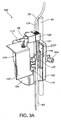
- the side of base unit 110 includes a door 103 that may be slid open or closed to expose or cover a component receiving portion 119 of base unit 110. As shown in FIGS. 2 and 4 , door 103 may be slid completely closed to cover the component receiving portion 119 from view. As illustrated in FIGS. 3A and 3B , door 103 is slid open to expose component receiving portion 119 of base unit 110. When door 103 is open, fluid pathway module 120 can be releasably mounted or removed from component receiving portion 119, e.g., using a handle 121. A guide 144 extends from the side of component receiving portion 119 to align and secure fluid pathway module 120 to base unit 110.
- FIG. 3A shows fluid pathway module 120 partially installed on base unit 110 and FIG. 3B shows fluid pathway module 120 fully installed on base unit 110.
- fluid pathway module 120 when fluid pathway module 120 is mounted to base unit 110, fluid pathway module 120 is positioned to receive gas from base unit 110.
- fluid pathway module 120 is also configured to receive liquid from a liquid supply line 75 via liquid inlet 124. Liquid may be supplied to fluid pathway module 120, for example, via a sterile water bag (not shown) that is suspended above humidification system 100.
- the sterile water bag may be punctured by a tube spike (not shown), with water being gravity fed from the water bag into fluid pathway module 120 via liquid supply line 75.
- a tube spike is disclosed in U.S. Patent Application Serial No. 10/918,515 owned by the Assignee of the present invention.
- liquid is stored within reservoir 32 (shown schematically in FIG. 1 ) in fluid pathway module 120 that is provided to receive humidification fluid from the water bag as well as recirculated humidification fluid.
- the circulated humidification fluid/liquid in fluid pathway module 120 liquid does not flow through base unit 110.
- Liquid contained in fluid pathway module 120 is vaporized in vapor transfer device 99 and combined with gas from base unit 110 to generate humidified breathing gas.
- a delivery tube 85 is releasably coupled to a breathing gas outlet 125 of fluid pathway module 120 to deliver humidified breathing gas to the patient.
- rear panel 102 of base unit 110 includes a pressure relief valve 91 that vents excess gas from base unit 110 if gas pressure supplied to base unit 110 from gas inlet ports 101a, 101b is too high.
- Base unit 110 also includes a service access cover 92 which is coupled to the rear panel 102 of base unit 110. Service access cover 92 may be removed from base unit 110 to provide access to internal components within base unit 110.
- an electrical cord 65 is coupled to base unit 110 to power humidification system 100.
- an internal battery (not shown) within base unit 110 may provide DC power to humidification system 100.
- Humidification system 100 may operate on DC power, for instance, when a patient is being transported from one location to another or during power interruptions, thus providing humidification system 100 portability and continued operations.
- the heater (not shown) that heats the fluid in fluid pathway module 120 does not operate in battery mode.
- humidification system 100 has a front panel 104 that includes a display panel 105, such as a liquid crystal display (LCD) or light emitting diode (LED) display that provides visual indication of user settings and status conditions of humidification system 100.
- the user settings may include user adjustable settings such as temperature 106a, flow rate 106b, and oxygen saturation level 106c of the breathing gas to be delivered to the patient.
- User settings may be adjusted, for example, via user interface 107.
- User interface 107 includes buttons 108a, 108b, LEDs 109a, 109b, and knob 111 to adjust and monitor operating conditions of humidification system 100. Additional aspects of the display panel 105 and user interface 107 will be described in further detail below according to aspects of humidification system 100 operation.
- FIG. 5 a detailed schematic diagram of humidification system 100 showing gas and fluid flow paths is illustrated. Schematic representations of base unit 110, fluid pathway module 120, and vapor transfer device 99 are shown. Fluid pathway module 120 is configured to be releasably mounted to base unit 110, and vapor transfer device 99 is configured to be releasably mounted to fluid pathway module 120.
- Base unit 110 includes controls for operation of humidification system 100 and has inlet ports configured to receive gas 50a, 50b, such as medical air and oxygen.
- Gas input into base unit 110 is controlled by two proportional solenoids PSOL1, PSOL2 that regulate the flow of gas 50a, 50b, respectively, into base unit 110.
- Proportional solenoids PSOL1, PSOL2 respectively, to regulate gas input flow into base unit 110.
- Gas pressure sensors PS1, PS2 monitor gas pressure upstream of solenoids PSOL1, PSOL2, respectively.
- Check valves 51a, 51b direct gas flow into gas blending device 84 and prevent reverse flow of gas 50a, 50b.
- gas flow rate of air 50a and oxygen gas 50b are monitored by mass flow sensor MFS1, MFS2, respectively, positioned on gas blending device 84.
- Air 50a and oxygen gas 50b are blended in gas blending device 84 and blended gas pressure is monitored by gas pressure sensor PS4.
- An oxygen sensor OS1 is coupled to a three-way solenoid valve SOL1 and monitors the oxygen saturation level of the blended gas. If the oxygen saturation level of the blended gas is below a user setpoint, proportional solenoid valve PSOL1 feeds additional oxygen gas 50b into the blended gas. Likewise, if oxygen saturation level of the blended gas is above a user setpoint, proportional solenoid valve PSOL1 reduces the amount of oxygen gas 50b into the blended gas.
- Gas pressure sensor PS4 is coupled to a microcontroller (not shown) and monitors the pressure of the blended gas. If the blended gas pressure exceeds a certain safety threshold, humidification system 100 emits an audible and a visual alarm. Additionally, when gas pressure sensor PS4 senses a low pressure, gas flow is limited by system 100.
- blended gas 60 is delivered to vapor transfer device 99, which is mounted to fluid pathway module 120.
- Sensors CS1, CS2 positioned within a base unit interface, such as component receiving portion 119, shown in FIG. 3 , of base unit 110 detect the presence of vapor transfer device 99 coupled to fluid pathway module 120.
- sensors CS1, CS2 may read a barcode or optically detect an indicator on vapor transfer device 99 when fluid pathway module 120 is mounted to base unit 110.
- Fluid pathway module 120 receives water, e.g. from a water bag 33, into reservoir 32.
- Two water level sensors LS1, LS2 on base unit 110 monitor water level within reservoir 32. For example, water level may be monitored by optical detection, as will be described in further detail below.
- Pump portion PMP1 is operationally coupled to a stator STA1 of base unit 110 to pump water from reservoir 32 to a heater HTR1.
- Heater HTR1 receives thermal energy from base unit heater HTR2 to heat water to a user specified temperature.
- a temperature switch controls heater HTR2 on base unit 110 to provide a safety backup to prevent water in fluid pathway module 120 from overheating.
- Heated water is pumped to a closed double lumen of a patient delivery tube 85 that is coupled to fluid pathway module 120. Heated water is recycled from delivery tube 85 into vapor transfer device 99.
- heated water is supplied through patient delivery tube 85 to minimize water condensation of breathing gas 80 and to maintain the temperature of breathing gas 80 as it makes its way to the patient.
- Infrared temperature sensors IR1, IR2 monitor the temperature of the water being delivered to and returned from delivery tube 85 and provide feedback to system controller (not shown) in order to maintain a desired temperature of the breathing gas at the outlet of delivery tube 85. Additional aspects of exemplary delivery tube 85 and vapor transfer device 99 are described in U.S. Patent Application Publication No. 2003/0209246 and U.S. Patent Application Publication No. 2004/0245658 .
- Blended gas from base unit 110 is combined with heated water vapor in vapor transfer device 99 to generate heated and humidified breathing gas 80.
- the heated and humidified breathing gas 80 is delivered to a breathing gas lumen of the patient delivery tube 85. Excess heated water delivered to vapor transfer device 99 may be recycled into water reservoir 32.
- Bubble sensor BS1 monitors air bubbles in reservoir 32 and bubble sensor BS2 monitors the presence of water droplets in the breathing gas 80 to determine when vapor transfer device 99 and/or fluid pathway module 120 should be replaced.
- fluid pathway module 120 has a continuous duty life of about 720 hours and about a 1000 hour test life.
- Gas blending device 84 may be constructed from a first, generally planar portion 71 ( FIGS. 6A , 6B , 6C ) and a second generally planar portion 81 ( FIGS. 7A , 7B ).
- Planar portions 71, 81 each include complementary channels such that when planar portions 71, 81 are assembled together, flow passages are formed within gas blending device 84.
- First portion 71 is configured to mate with second portion 81 shown in FIGS. 7A-7B to provide a fully assembled gas blending device 84.
- first portion 71 is secured to second opposing portion 81, edges 72a, 72b of first portion 71 form an air tight seal with edges 82a, 82b of second portion 81 to prevent gas leakage and provide efficient gas blending operation.
- Gas blending device 84 is configured to be installed internally within base unit 110.
- Pilot holes 77a-c and pins 78a-c are positioned on first portion 71 of gas blending device 84 to align and secure the first portion 71 to the second opposing portion 81 shown in FIGS. 7A-7B .
- pilot holes 77a-c and pins 78a-c provide additional connection surface area and mechanical strength to the gas blending device 84.
- Pilot holes 87a-c and pin inserts 88a-c are positioned on the body of second portion 81 and are configured to mate with pilot holes 77a-c and pins 78a-c of the first portion 71.
- First portion 71 of gas blending device 84 includes two channels 73a, 73b that are each configured to receive gas through inlets 74a, 74b, respectively. Channels 73a, 73b direct gas to blending channel 73c. Blending channel 73c leads to main terminal channel 73d where blended gas may exit through second portion 81 and flow to a gas outlet, shown as gas outlet 649 in FIG. 8C , of base unit 110. Upstream of main terminal channel 73d is a pressure relief outlet 74c that functions as a secondary gas exit if gas pressure exceeds a predetermined value.
- pressure relief outlet 74c is part of a pressure relief valve system, which may open or close pressure relief valve 91 (shown schematically in FIG. 5 ), depending on gas pressure within gas blending device 84.
- Passage 73e provides for gas flow to oxygen sensor OS1 (shown schematically in FIG. 5 ).
- Second portion 81 of gas blending device 84 is configured to mate with the first portion 71 shown in FIGS. 6A-6C .
- Second portion 81 includes channels 83a, 83b having fins 66a, 66b within each channel 83a, 83b. Fins 66a, 66b promote laminar flow across mass flow sensors MFS1, MFS2 (shown schematically in FIG. 5 ) installed through openings 76a, 76b of the first portion 71 ( FIG. 7B ) of gas blending device 84.
- Walls 69a, 69b define channel 83a such that when gas blending portion 71 ( FIG. 6B ) mates with the second opposing portion 81 ( FIG. 7B ), air tight channels are formed.
- Channels 83a, 83b direct gas to a blending channel 83c that includes a tortuous path 67 to efficiently mix gas together prior to reaching terminal channel 83d.
- Channel 83e mates with channel 73e to form a passage to oxygen sensor OS1 (shown schematically in FIG. 5 ).
- gas metering operation of humidification system 100 determines the precise flow rate of gas within each channel 73a, 83a to obtain a blended gas mixture having an oxygen saturation level between 21% and 100% O 2 .
- Oxygen saturation level of blended gas mixture 60 shown in FIG. 1 may be monitored by oxygen sensor OS1, which is shown in FIG. 5 .
- first portion 71 of gas blending device 84 includes sensor openings 76a, 76b which open into either end of passage 76c. Passage 76c is in fluid communication with mass flow sensor MFS1 (not shown in FIGS. 6A-6C ), which monitors gas flow rate in channel 73a to control the gas metering operation of humidification system 100.
- FIG. 6C illustrates an exterior view of first portion 71 of gas blending device 84.
- First portion 71 includes threaded inserts 79a, 79b to mount mass flow sensor MFS1.
- channel 83b of second portion 81 includes sensor openings 86a, 86b which open into either end of passage 86c. Passage 86c is in fluid communication with mass flow sensor MFS2 (not shown in FIGS. 7A-7B ), which monitors gas flow rate in channel 83a to control the gas metering operation of humidification system 100.
- FIG. 7E illustrates an exterior view of second portion 81 of gas blending device 84. Second portion 81 includes threaded inserts 89a, 89b to mount mass flow sensor MFS2 through openings 86a, 86b. Main gas outlet 68 provides an exit for blended gas to flow to gas outlet 649, shown in FIG. 8C , of base unit 110.
- the gas flow rate detected by mass flow sensor MFS1, MFS2 in channel 73a may be sent to a microcontroller that controls proportional solenoid valves PSOL1, PSOL2.
- Proportional solenoid valve PSOL1 or PSOL2 may vary gas input flow in channel 73a by increasing or decreasing gas flow through the inlet 74a.
- an adequate ratio of gas flow may be supplied to channel 73a to obtain a desired blended oxygen saturation level.
- oxygen sensor OS1 which may be positioned in oxygen sensor opening 74d, is calibrated to 100% O 2 during a system power up sequence. Once calibrated, the oxygen sensor OS1 measures oxygen content of blended gas to ensure that blended gas is within 98% to 102% of a selected oxygen percentage setpoint.
- the microcontroller may adjust proportional solenoid valves PSOL1, PSOL2 to increase the flow of oxygen gas 50b and/or decrease the flow of air 50a.
- the microcontroller may adjust proportional solenoid valves PSOL1, PSOL2 to decrease the flow of oxygen gas 50b and/or increase the flow of air 50a through inlet 74b or 74a.
- Base unit chassis 640 contains the interfaces with fluid pathway module 120. References to these figures also include references to sensors BS1, BS2, electronic readers CS1, CS2, water level sensors LS1, LS2, temperature sensors IR1, IR2, pump stator STA1, and heater HTR2, which are shown schematically in FIG. 5 and with reference to base unit 110 in FIG. 8G . It will be appreciated that base unit chassis 640 houses the electronic components of humidification system 100 and is configured such that liquid does not flow internally through base unit 110.
- base unit chassis 640 includes a front portion 640a into which display panel 105 may be installed. Threaded inserts 641a-d are provided on front portion 640a of chassis 640 to secure display panel 105 to base unit chassis 640. When display panel 105 is secured, front panel 104 may be fitted over a front edge 642 of base unit chassis 640 to prevent access to the electrical connections of display panel 105. After installation of front panel 104, slidable door 103 as shown in FIG. 3 , may be secured to base unit chassis 640 via threaded inserts 643a, 643b located on the top and side of base unit chassis 640.
- base unit chassis 640 includes a component receiving portion 619 configured to receive fluid pathway module 120.
- a guide 644a extends along the side of the component receiving portion 619 to align and secure fluid pathway module 120 to base unit 100.
- Base unit chassis 640 has a seat 645 to support fluid pathway module 120 and a seat opening 646 in which a pump portion such as stator STA1 may be installed via threaded inserts 647a-c.
- stator STA1 shown schematically in FIG. 5
- pump portion PMP1 shown schematically in FIG. 5
- stator STA1 may drive pump portion PMP1 which may be an impeller that is magnetically driven by stator STA1 to advance liquid through a liquid passage of fluid pathway module 120.
- pump portion PMP1 may be an impeller that is magnetically driven by stator STA1 to advance liquid through a liquid passage of fluid pathway module 120.
- An exemplary embodiment of a pump having a separate pump portion PMP1 and a separate stator portion STA1 is manufactured by Laing Thermotech, Inc., located in Chula Vista, California.
- the entire pump portion may be provided only on base unit 110 to provide a low cost, disposable fluid pathway module 120.
- the entire pump portion may be provided only on fluid pathway module 120
- Base unit chassis 640 includes a recessed portion 648 that has a gas outlet 649.
- recessed portion 648 aligns with and supports a gas receiving portion 130, shown in FIG. 10B , of fluid pathway module 120.
- the gas receiving portion of fluid pathway module 120 includes a gas inlet which is configured to couple to the gas outlet 649 of base unit 110 to provide an air tight seal through which gas may be transferred from base unit 110 to the gas passage of fluid pathway module 120.
- the component receiving portion 619 of base unit chassis 640 has a rectangular opening 651 into which heater HTR2, shown in FIG. 5 , such as a heat conduction plate may be installed.
- heater HTR2 of base unit 110 contacts heater HTR1, FIG. 5 , of fluid pathway module 120, FIG. 3 .
- Heater HTR1 of fluid pathway module 120 may also be a heat conduction plate HTR2 such that when electrical current is supplied to the heat conduction plate of base unit 110, energy is transferred to heat conduction plate HTR1 of fluid pathway module 120. Thermal energy received by heat conduction plate HTR1 of fluid pathway module 120 is used to heat the liquid contained within fluid pathway module 120 for delivery to the patient at a temperature specified by the user.
- the user may adjust the temperature setting of humidification system in 1°C steps to a maximum temperature of 43° C and a minimum temperature of 33° C.
- a temperature sensor opening 652a in base unit chassis 640 is configured to receive temperature sensor IR1 to monitor the temperature of the liquid that is supplied to delivery tube 85.
- Base unit chassis 640 also includes a bubble sensor opening 653a adjacent temperature sensor opening 652a.
- Bubble sensor opening 653a is configured to receive bubble sensor BS1 that monitors the formation of air bubbles in liquid reservoir 32 of fluid pathway module. Additional aspects of bubble sensor BS1 will be described in further detail below.
- two water level sensor openings 654a, 654b are positioned on base unit chassis 640.
- Water level sensor openings 654a, 654b are each configured to receive a water level sensor LS1, LS2 to monitor the water level within liquid reservoir 32 of fluid pathway module 120.
- optical water level sensors LS1, LS2 are aimed at reflectors 128a, 128b, shown in FIG. 10A , located at the top and bottom of liquid reservoir 32 to determine when the liquid reservoir 32 is full, low, or empty. Additional aspects of water level sensors LS1, LS2, shown in FIG. 5 , will be described in further detail below.
- FIG. 8B illustrates a rear view of base unit chassis 640 in which water level sensors LS1, LS2 may be installed.
- water level sensor openings 654a, 654b are each configured to receive a water level sensor LS1, LS2, respectively.
- Water level sensors LS1, LS2 may be mounted to base unit chassis 640 via threaded inserts 655a-d.
- Rear panel 102 shown in FIG. 4 , may be fitted over rear edge 656 of base unit chassis 640 to restrict access to the electrical connections of water level sensors LS1, LS2.
- FIG. 8C illustrates a side view of base unit chassis 640 in which fluid pathway module 120, shown in FIG. 3 , may be releasably mounted.
- An electronic reader opening 657 on base unit chassis 640 is configured to receive electronic reader CS1, CS2 that detects the type of vapor transfer device 99 coupled to fluid pathway module 120.
- Vapor transfer device 99 may be, for example, a disposable, cartridge that is labeled with an indicator 194 such as a sticker or barcode.
- a high flow vapor transfer device 99 is labeled with an all-reflective sticker while a low flow vapor transfer device 99 is labeled with a portion reflective/portion non-reflective sticker.
- Electronic reader CS1, CS2 may monitor the optical properties of the sticker to identify the type of vapor transfer device 99 installed in humidification system 100.
- indicator 194 is read by electronic reader CS1, CS2
- a signal is sent to a microprocessor (not shown) to control the gas metering operation of humidification system 100.
- the microcontroller may limit the flow rate of the breathing gas being delivered to a setpoint between 0.5 LPM (liters per minute) and 8 LPM. If a high flow rate vapor transfer device 99 is installed, the microcontroller may limit the flow rate between 8 LPM and 40 LPM.
- humidification system 100 when a user attempts to adjust the flow rate setpoint beyond the limits defined by the microcontroller, humidification system 100 generates an auditory warning and prevents the setpoint from deviating beyond the maximum and minimum flow rate limits of a high flow or low flow vapor transfer device 99.
- a temperature sensor opening 652a of base unit chassis 640 is configured to receive infrared temperature sensor IR1 that detects the temperature of liquid in fluid pathway module 120.
- a second temperature sensor opening 652b is configured to receive second infrared temperature sensor IR2 that detects the temperature of liquid returning back to fluid pathway module 120 from delivery tube 85.
- monitoring of the two temperatures allows humidification system 100 to efficiently operate heater HTR2, which is mounted through heater opening 651 of base unit chassis 640.
- activation and deactivation of HTR2 may be controlled by a PID (proportional-integral-derivative) feedback controller to maintain a consistent temperature of the breathing gas being delivered to a patient.
- PID proportional-integral-derivative
- Adjacent the temperature sensor openings 652a, 652b of base unit chassis 640 are bubble sensor openings 653a, 653b that are each configured to receive a bubble sensor BS1, BS2, respectively.
- air bubbles may be detected in liquid reservoir 32 of fluid pathway module 120 due to air permeating under pressure through the exchange media in vapor transfer device 99 of fluid pathway module 120.
- the water and gas passages of fluid pathway module 120 are connected to vapor transfer device where a portion of the liquid is transferred to the gas. Over time, as gas and liquid flow internally through vapor transfer device, the core of vapor transfer device may begin to degrade such that the mixing interface between the gas and liquid passages erodes.
- Bubble sensors BS1, BS2 that are mounted in bubble sensor openings 653a, 653b of base unit chassis 640 detect these conditions and send appropriate signals to the microcontroller to warn a user of when either or both conditions exist.
- bubble sensor BS1 shown in FIG. 5 , of humidification system 100 detects the rate at which air bubbles are formed in liquid reservoir 32 of fluid pathway module 120. If the bubble formation rate rises above a predetermined level, an auditory warning may be generated and vapor transfer device fault icon 112c, shown in FIG. 13 , may illuminate on display panel 105 to indicate that vapor transfer device 99 should be replaced with a new cartridge.
- second bubble sensor BS2 detects the rate at which liquid droplets form in the gas passage of vapor transfer device 99. If the droplet formation rate exceeds a predetermined level, the gas metering and warming operations of humidification system 100 may be suspended. An auditory warning may be generated and fluid pathway module 120 icon 115, shown in FIG. 13 , may illuminate on display panel 105, shown in FIG. 13 , to indicate that fluid pathway module 120 should be replaced.
- FIG. 8D illustrates a side view of base unit chassis 640 in which electronic reader CS1, CS2, temperatures sensors IR1, IR2, bubble sensors BS1, BS2, and heater HTR2 may be installed.
- electronic reader opening 657 is configured to receive electronic reader CS1, CS2 which may be installed on base unit chassis 640 via threaded inserts 658a, 658b.
- Temperature sensor openings 652a, 652b are each configured to receive temperature sensor IR1, IR2, which may be mounted to base unit chassis 640 via threaded inserts 659a, 659b and bubble sensors BS1, BS2 may be mounted to bubble sensor openings 653a, 653b via threaded inserts 661a-c.
- Heater HTR2 such as a heat conduction plate may be mounted to the heat conduction plate opening 651 via threaded inserts 663a-d.
- a side panel (not shown) may be fitted over the rear edge 664 of base unit chassis 640 to restrict access to the electrical connections of electronic components, such as readers CS1, CS2, bubble sensors BS1, BS2 ( FIG. 5 ), temperature sensors IR1, IR2, and heater HTR1, which are all shown schematically in FIG. 5 .
- FIG. 8E illustrates a cross-sectional view of base unit chassis 640 along the 8E-8E line shown in FIG. 8D .
- base unit chassis 640 includes a recessed portion 648 configured to receive a gas receiving portion of fluid pathway module 120.
- Gas outlet 649 of recessed portion 648 is configured to receive a gas inlet of fluid pathway module 120 to supply gas into the gas passage of fluid pathway module 120.
- Water level sensor openings 654a, 654b are disposed along the top and bottom of the component receiving portion 619 and are configured to receive water level sensors LS1, LS2 to detect water level in fluid pathway module 120.
- Guide 644a extends from the side of the component receiving portion 619 to align and secure fluid pathway module 120 to base unit 110.
- FIG. 8F illustrates a top view of base unit chassis 640.
- base unit chassis 640 includes a component receiving portion 619 having a seat 645 that is configured to seat fluid pathway module 120.
- a seat opening 646 is provided to receive pump portion STA1 of base unit 110 which may be secured to base unit 110 via threaded inserts 647a-c.
- Guides 644a, 644b extend from the side of the component receiving portion 619 to align and secure fluid pathway module 120 to base unit 110.
- a recessed portion 648 of base unit chassis 640 includes a gas outlet 649 which receives gas inlet of fluid pathway module 120. Opening 651 is positioned on base unit chassis 640 to receive heater HTR2.
- Pump portion 96 is configured to mount to seat opening 646, shown in FIG. 8A , of base unit chassis 640 via openings 97a-d on pump portion 96.
- Installation bracket 99 facilitates alignment and installation of pump portion 96
- Pump portion 96 such as stator STA1 shown in FIG. 5 , is configured to operationally mate with pump portion PMP1 of fluid pathway module 120 to advance liquid through the liquid passage of fluid pathway module 120.
- pump portion PMP1 of fluid pathway module 120 is a rotatable impeller 98 that magnetically couples to pump portion 96. When impeller 98 is operationally mated with pup portion 96, rotation of impeller 98 drives the rotation of pump portion PMP1, thereby increasing pressure and liquid flow within fluid pathway module 120.
- Fluid pathway module 120 is configured to be releasably mounted to base unit 110 to accommodate reuse of base unit 110 and selective disposal of fluid pathway module 120.
- Fluid pathway module 120 includes handle 121 that may be used to insert and remove fluid pathway module 120 from base unit 110.
- heater HTR1 contacts heater HTR2.
- Pump portion STA1 of base unit 110 engages pump portion PMP1 of fluid pathway module 120.
- fluid pathway module 120 includes liquid inlet 124 and gas outlet 125. Liquid inlet 124 receives liquid from supply line 75 and gas outlet 125 delivers heated and humidified breathing gas to a patient via delivery tube 85.
- liquid such as water
- a sight glass 126 on the side of fluid pathway module 120 provides visual indication of liquid amount in reservoir 32 via a plastic ball 127 floating within reservoir 32.
- Two reflectors 128a, 128b are visible through the sight glass 126 and are positioned to align with water level sensors LS1, LS2.
- Water level sensors LS1, LS2 of base unit 110 optically sense water level in fluid pathway module 120 by monitoring light reflection off reflectors 128a, 128b. For example, when reservoir 32 is full, light reflection from reflector 128a is blocked by plastic ball 127 and the humidification system microcontroller (not shown) determines that water level in fluid pathway module 120 is full.
- FIG. 10B illustrates a side view of fluid pathway module 120.
- Fluid pathway module 120 includes heater HTR1 in the form of heat conduction plate 122 that heats liquid stored in fluid pathway module 120 by receiving thermal energy from heater HTR1.
- Adjacent heat conduction plate 122 are two temperature reflectors 129a, 129b that are positioned to align with two infrared temperature sensors IR1, IR2.
- temperature sensor IR1, aligned with temperature reflector 129a monitors the temperature of liquid heated by heat conduction plate 122 and temperature sensor IR2, aligned with temperature sensor reflector 129b, monitors the temperature of liquid returning to fluid pathway module 120 from delivery tube 85.
- Fluid pathway module 120 includes gas inlet 130 which is configured to receive gas from base unit 110.
- gas inlet 130 When fluid pathway module 120 is mounted to base unit 110, as shown in FIG. 3 , an air tight seal is formed between gas inlet 130 and gas outlet 649 of base unit chassis 640, shown in FIG. 8C .
- gas received through gas inlet 130 and liquid stored in reservoir 32 flow through passages within fluid pathway module 120 into vapor transfer device 99.
- vapor transfer device 99 contains an infuser with a membrane, such as a vapor transfer cartridge including a plurality of porous hollow fibers, having a liquid side and a breathing gas side.
- Liquid from humidification reservoir 32 is introduced from reservoir 32 into breathing gas by passing liquid vapor across a porous membrane in vapor transfer device 99 to humidify the breathing gas.
- Vapor transfer device 99 is mounted to fluid pathway module 120 to form a vapor transfer assembly. Vapor transfer device 99 combines water vapor and gas received from fluid pathway module 120 to form heated and humidified breathing gas. Heated and humidified breathing gas flows from vapor transfer device 99 through outlet 125, shown in FIG. 10A of fluid pathway module 120, and to the patient via delivery tube 85.
- Indicator 194 such as a barcode or sticker, is positioned on vapor transfer device 99 such that when vapor transfer device 99 is coupled to fluid pathway module 120 and mounted on base unit 110 ( FIG. 3 ), an electronic reader CS1, CS2 aligns with indicator 194.
- the type of vapor transfer device 99 installed on fluid pathway module 120 such as a low flow or high flow cartridge, described above, may be determined by a microcontroller (not shown) of humidification system 100.
- the internal core of vapor transfer device 99 may degrade, resulting in the mixing of gas and water vapor within vapor transfer device 199 becoming less efficient.
- gas pockets may enter the liquid passage of fluid pathway module 120 so that air bubbles form in liquid reservoir 32.
- droplets of liquid may enter the gas passage.
- Bubble sensors BS1, BS2 align with bubble reflectors 131a, 131b on fluid pathway module 120.
- bubble sensor BS1 aligned with bubble reflector 131a monitors air bubble formation within liquid reservoir 32 and bubble sensor BS2 aligned with bubble reflector 131b monitors liquid droplets in the gas passage.
- signals may be sent to humidification system microcontroller to generate auditory warnings and illuminate fault icons 115, 112c on display panel 105, shown in FIG. 13 , to warn a user of these conditions. Additional aspects of warnings and fault icons will be described in further detail below.
- FIGS. 11A and 11B illustrate exploded views of a portion of fluid pathway module 120 shown in FIGS. 10A and 10B .
- main body 120a of fluid pathway module 120 includes liquid reservoir 32 to store liquid received through liquid inlet 124.
- a water level sensor plate 133 having upper reflector 128a and lower reflector 128b is configured to be positioned within the reservoir 32 and is visible through sight glass 126.
- a non-reflective level ball 127 is configured to be positioned within the reservoir 32 such that it floats within reservoir 32 as previously described.
- Optical water level sensors LS1, LS2 monitor the light reflection from reflectors 128a, 128b, thereby determining the water level within reservoir 32.
- Main body 120a of fluid pathway module 120 includes heater HTR1 in the form of a heat conduction plate. Throughout device 100, heat is transferred from heater HTR2, located in base unit 110, to heater HTR1, located in fluid pathway module 120, via conduction. Heat is then transferred by conduction from heater HTR1 to liquid in reservoir 32 when fluid pathway module 120 is mounted to base unit 110.
- a temperature and bubble sensor plate 135 is adjacent heater portion 134 and is configured to couple with temperature reflectors 129a, 129b and bubble reflectors 131a, 131b.
- temperature and bubble sensor plate 135 is configured to fit over temperature reflector portions 129a, 129b and bubble reflector portions 131a, 131b.
- Main body 120a includes handle 121 which may be used to insert or remove fluid pathway module 120 from base unit 110.
- Tubular support structures 136a-e extend from the side of main body 120a.
- Tubular support structures 136a-e are configured to mate with vapor transfer device adapter 120b, shown in FIG. 12 .
- vapor transfer device 99 is configured to couple to support structures 136a-c such that passages defined by support structures 136a-c connect with passages of vapor transfer device 99.
- Liquid and gas may be exchanged through the passages to generate heated and humidified breathing gas in vapor transfer device 99.
- Heated and humidified breathing gas for example, may be supplied to gas outlet 125 of fluid pathway module 120, shown in FIG. 10A , through the passage defined by support structure 136a.
- heated liquid may be supplied to vapor transfer device 99 through the passage defined by support structure 136c and recycled through the passage defined by support structure 136b.
- vapor transfer device adapter 120b is configured to couple to main body 120a to fully assemble fluid pathway module 120.
- Vapor transfer device adapter 120b includes passages 137a-e that are configured to mate with support structures 136a-e of main body 120a.
- vapor transfer device adapter 120b includes gas inlet portion 130a configured to mate with reciprocal gas inlet portion 130b to form gas inlet 130.
- Gas inlet 130 receives gas from base unit 110 and channels gas to gas opening 138.
- Gas opening 138 is configured to connect to a gas passage of vapor transfer device 99 and supply gas into vapor transfer device 99.
- Gas from gas opening 138 and heated water from passage 137c are used in vapor transfer device 99 to generate heated and humidified breathing gas.
- heated and humidified breathing gas exits vapor transfer device 99 through passage 137a and is delivered to breathing gas outlet 125 of fluid pathway module 120.
- excess water in vapor transfer device 99 from passage 137c is recycled back into liquid reservoir 32 through passage 137b.
- gas inlet 130 includes an air port ball 139a that is configured to be contained within cap 130b.
- An O-ring 139c is positioned at a distal end of cap 139b and provides a circumferential seal around a distal opening of the cap 139b.
- Cap cover 139d is positioned distally from O-ring 139c and is configured to seat O-ring 139c when cap cover 139d is secured around a portion of cap 139b.
- the air port ball 130a moves freely between O-ring 139c and distal opening 193a, 193b of gas inlet portions 130a, 130b.
- gas flow into gas inlet 130 causes air port ball 139a to move in a direction opposing gravity.
- air port ball 139a When gas flow through gas inlet 130 exceeds gravitational pull on air port ball 139a, air port ball 139a will "float”.
- air port ball 130a when gas is not supplied to gas inlet 130, air port ball 130a will contact and seal O-ring 139c to prevent air flow into gas outlet 649 ( FIG. 8C ) of base unit chassis 640 ( FIG. 8C ).
- air port ball 139a Under normal operating conditions, air port ball 139a will "float” between distal opening 193a, 193b and O-ring 139c, thereby providing gas flow through gas opening 138.
- gas only flows in one direction from base unit 110 into fluid pathway module 120.
- a flexible lip 139e is positioned between gas inlet portions 130a, 130b and adjacent gas opening 138.
- lip 139e when vapor transfer device 99 is coupled to fluid pathway module 120, lip 139e is deformably opened such that gas may flow into vapor transfer device 99.
- lip 139e is deformably sealed to prevent air from flowing in a direction from gas opening 138 into the gas outlet 130.
- Vapor transfer device 99 is releasably mounted to fluid pathway module 120 such that liquid and gas communication is provided between vapor transfer device 99 and fluid pathway module 120 (STEP 510).
- Fluid pathway module 120 is releasably mounted to base unit 110 such that breathing gas 50a, 50b supplied into base unit 110 flows into fluid pathway module 120 and through vapor transfer device 99 (STEP 520). Breathing gases 50a, 50b are blended inside a gas blending device 84 to form a blended gas 60 (STEP 530).
- Thermal energy is transferred from base unit 110 to fluid pathway module 120, thereby heating liquid 70 in a liquid passage of fluid pathway module 120 (STEP 540).
- Liquid 70 is heated in fluid pathway module 120 and is used to heat and humidify blended gas 60 and maintain a desired temperature of breathing gas 80 (STEP 550).
- Heated liquid 70 and blended gas 60 are passed through vapor transfer device 99, thereby forming heated and humidified breathing gas 80, which is then delivered to a patient (STEP 560), e.g., via a nasal cannula (not shown).
- Front panel 104 of base unit 110 includes display panel 105 that provides visual indication of the operating conditions of humidification system 100.
- battery icon 113 may illuminate on display panel 105 to indicate that an internal battery (not shown) is charging. Battery icon 113 may flash to indicate that the battery backup time is reduced in the event that AC power is lost during charging. When the battery is fully charged, battery icon 113 automatically switches off.
- fluid pathway module fault icon 115 is illuminated.
- fluid pathway module fault icon 115 is switched off and water level sensors LS1, LS2 in base unit 110 are activated to detect water level in fluid pathway module 120. If the water level is low, a low water icon 116 flashes on/off and an audible alarm sounds to indicate that reservoir 32 of fluid pathway module 120 should be refilled by providing additional water through water supply line 75. If the water is empty, low water icon 116 in constantly illuminated an audible alarm sounds.
- an electronic reader CS1, CS2 is activated to detect the presence of vapor transfer device 99. If vapor transfer device 99 is not detected on fluid pathway module 120 or if bubble sensors BS1, BS2 detect that vapor transfer device 99 is worn, vapor transfer device fault icon 112c is illuminated.
- the type of vapor transfer device 99 installed is determined by electronic reader CS1, CS2. For example, if a high flow vapor transfer device 99 is detected, a high flow icon 112a is illuminated on the display panel 105. If a low flow vapor transfer device is detected 99, a low flow icon 112b is illuminated.
- detection of fluid pathway module 120 and vapor transfer device 99 is performed concurrently such that when vapor transfer device 99 is detected, the system automatically determines that fluid pathway module 120 is installed on base unit 110.
- Gas flow to the patient is a metered blending of the two input gases, such as medical air and oxygen.
- a closed feedback control loop exists between the proportional solenoids PSOL1, PSOL2 that control the flow of each gas, and mass flow MFS1, MFS2 sensors that measure the gas flow.
- a gas blending algorithm controls the gas blending process.
- a gas blending algorithm suitable to control the gas blending process will be understood by one having ordinary skill in the art from the description herein.
- Mass flow sensors MFS1, MFS2 measure the flow rates of medical air and oxygen gases.
- Proportional solenoids PSOL1, PSOL2 control the flow rates of the gases.
- Each valve PSOL1, PSOL2 is controlled by a digital to analog converter (DAC), not shown.
- DAC digital to analog converter
- SLPM Standard Liters Per Minute
- the lookup table includes 201 entries that are defined for each of mass flow sensors MFS1, MFS2.
- the lookup table is indexed by engineering units in 0.25 SLPM increments, and returns values corresponding to the output of mass-flow sensors MFS1, MFS2 in raw 12-bit A/D counts. Fractional indices may be resolved through linear interpolation between table entries.
- oxygen saturation level 106c is set for 21% for air and 100% for oxygen.
- An audible alarm sounds if the user attempts to edit or otherwise adjust the value for oxygen saturation level 106c.
- the user attaches an air or an oxygen supply to one of gas inlet ports 101a, 101b while system 100 is in standby mode.
- the user attaches gas supply lines to each of gas inlet ports 101a, 101b while system 100 is in standby mode. If either gas supply loses pressure while system 100 is in dual gas operation, an audible alarm sounds.
- auditory warning alarms may be generated.
- auditory tones and alarms may be generated concurrently when warning indicators are displayed on display panel 105.
- alarms may be programmed with unique auditory patterns depending of the priority of the warning. For example, a low priority auditory warning may sound briefly to indicate the occurrence of an event that does not require immediate user attention, whereas a higher priority auditory warning may sound continuously to indicate that immediate attention is required.
- Warning alarms may be muted by pressing the mute button 108a of the user interface 107.
- pressing the mute button 108a illuminates LED 109a to provide visual indication that warning alarms are muted.
- pressing alarm button 108a mutes low priority auditory warnings, while higher priority auditory warnings may remain auditory.
- alarm button 108a function may be programmed with additional user adjustable settings such as controlling the brightness of display panel 105. For example, pressing alarm button 108a for a period of time may adjust the brightness of display panel 105.
- pressing encoder knob 111 cycles through user settings that can be adjusted. Pressing the encoder knob 111 once, for example, may activate the temperature adjustment setting and pressing encoder knob 111 in succession may cycle through additional user settings that can be adjusted. In an exemplary embodiment, pressing encoder knob 111 causes the user setting that is activated to blink on display panel 105, thus indicating the specific user setting that may be adjusted. In an exemplary embodiment, rotating encoder knob 111 while in an activated user setting allows the current user setting setpoint to be adjusted.
- encoder knob 111 may increase the setpoint and rotating knob 111 counterclockwise may decrease the setpoint.
- encoder knob 111 has an acceleration feature, in which turning knob 111 faster causes the setpoint to increase or decrease in larger steps.
- pressing "Standby/Run” button 108b transitions humidification system from “standby” mode to "run” mode.
- status LED 109b may be illuminated to indicate that the gas metering and heating operations of the system are activated to deliver heated and humidified gas to the patient.
- Base unit 110 includes gas pressure sensors to detect if the breathing gas delivery tube 85 is blocked and if gas supply into base unit 110 is too low or too high.
- a tube fault icon 117 may be lit on display panel 105 when base unit senses a pressure indicating that the breathing gas delivery tube 85 is kinked or blocked.
- Gas supply fault icon 118 may be displayed when a gas supply problem, such as low or high gas pressure is input to humidification system 100.
Landscapes
- Health & Medical Sciences (AREA)
- Emergency Medicine (AREA)
- Pulmonology (AREA)
- Engineering & Computer Science (AREA)
- Anesthesiology (AREA)
- Biomedical Technology (AREA)
- Heart & Thoracic Surgery (AREA)
- Hematology (AREA)
- Life Sciences & Earth Sciences (AREA)
- Animal Behavior & Ethology (AREA)
- General Health & Medical Sciences (AREA)
- Public Health (AREA)
- Veterinary Medicine (AREA)
- Air Humidification (AREA)
- Accommodation For Nursing Or Treatment Tables (AREA)
Description
- This invention relates to apparatus and methods for respiratory tract therapy. More particularly, this invention relates to an apparatus configured to deliver heated and humidified breathing gas to a patient.
- Respiratory airway therapies are recognized medical treatments that enhance breathing by delivering breathing gas to the respiratory tract of patients. Respiratory devices such as humidifier/ventilator systems, however, include parts that may be at risk of contamination due to contact with water or water vapor. While disinfection protocols have been developed to minimize and control bacterial growth, there remains a need for an improved apparatus for respiratory tract therapy that can be used in various settings including clinical and hospital settings that reduces the risk of bacterial contamination. There also remains a need for improved methods of respiratory airway therapy.
-
US 4,430,994 describes respiratory gas heating and humidifying methods and apparatus, wherein respiratory gas is delivered to a patient enclosure past a variably heated surface over which a film of water migrates and whose wetness is visible through a transparent cover which is recessed at the water film side to define water inlet, gas flow, and excess water removal paths. -
WO 2007/038152 A2 discloses a modular pressure support system which comprises a patient circuit, a docking assembly, and a tank. The patient circuit delivers a pressurized flow of breathable gas to a patient. The docking assembly has an inlet and an outlet that is adapted to receive the pressurized flow of breathable gas, and is also adapted to be connected with the patient circuit. The tank is constructed and arranged to be removably connected with the docking assembly, and enables the pressurized flow of breathable gas to pass therethrough. The tank is also adapted to contain a liquid such that a humidity level of the pressurized flow of breathable gas is elevated as the pressurized flow of breathable gas passes therethrough. - In one aspect, the invention provides a humidification system configured to deliver humidified breathing gas to a patient. The humidification system includes a vapor transfer unit and a base unit. The vapor transfer unit includes a liquid passage, a breathing gas passage, and a vapor transfer device positioned to transfer vapor to the breathing gas passage from the liquid passage. The system includes a base unit that releasably engages the vapor transfer unit to enable reuse of the base unit and selective disposal of the vapor transfer unit. The liquid passage is not coupled to the base unit for liquid flow therebetween when the vapor transfer unit is received by the base unit.
- In another aspect, the humidification system configured to deliver humidified breathing gas to a patient includes a vapor transfer unit and a base unit. The vapor transfer unit includes a liquid passage, a breathing gas passage, and a vapor transfer device positioned to transfer vapor to the breathing gas passage from the liquid passage. The base unit releasably engages the vapor transfer unit. The base unit has at least one sensor positioned to sense a parameter in the liquid passage of the vapor transfer device.
- In yet another aspect, the humidification system configured to deliver humidified breathing gas to a patient includes a vapor transfer unit and a base unit. The vapor transfer unit has a liquid passage and a first pump portion positioned to advance liquid through the liquid passage. The base unit releasably engages with the vapor transfer unit. The base unit has a second pump portion adapted to operationally mate with the first pump portion to advance liquid through the liquid passage of the vapor transfer unit when the base unit engages the vapor transfer unit.
- In still another aspect, the humidification system is configured to deliver heated and humidified breathing gas to a patient and includes a vapor transfer unit and a base unit. The vapor transfer unit has a liquid passage and a first heater portion positioned to heat liquid in the liquid passage. The base unit releasably engages the vapor transfer unit to enable reuse of the base unit and selective disposal of the vapor transfer unit. The liquid passage is not coupled to the base unit for liquid flow therebetween when the vapor transfer unit is received by the base unit. The base unit has a second heater portion adapted to conduct heat to the first heater portion to heat liquid in the liquid passage of vapor transfer unit.
- In still yet another aspect, the invention provides a vapor transfer unit for use with a base unit of a humidification system for delivering heated and humidified breathing gas to a patient. The vapor transfer unit is configured to be releasably mounted to base unit to accommodate reuse of base unit and selective disposal of vapor transfer unit. The vapor transfer unit includes liquid and breathing gas passages and a vapor transfer device is positioned to transfer vapor to the breathing gas passage from the liquid passage. An impeller is positioned to advance liquid through the liquid passage and a sensor is positioned to sense a level of liquid in the liquid passage.
- The invention is best understood from the following detailed description when read in connection with the accompanying drawings, with like elements having the same reference numerals. This emphasizes that according to common practice, the various features of the drawings are not drawn to scale. On the contrary, the dimensions of the various features are arbitrarily expanded or reduced for clarity. Included in the drawings are the following figures:
-
FIG. 1 is a schematic representation of a humidification system according to an exemplary aspect of this invention; -
FIG. 2 is a front perspective view of an exemplary embodiment of the humidification system in accordance with the present invention; -
FIG. 3A is a side perspective view of the humidification system shown inFIG. 2 , with a vapor transfer cartridge partially inserted into a base unit; -
FIG. 3B is a side perspective view of the humidification system shown inFIG. 2 , with the vapor transfer cartridge fully inserted into the base unit; -
FIG. 4 is rear perspective view of the humidification system shown inFIG. 2 ; -
FIG. 5 is a schematic representation of the humidification system shown inFIGS. 2 ,3 , and4 according to aspects of the invention; -
FIG. 6A is a perspective view of a first portion of a gas blending device according to an aspect of the invention; -
FIG. 6B is an interior view of the first portion of the gas blending device shown inFIG. 6A ; -
FIG. 6C is an exterior view of the first portion of the gas blending device shown inFIG. 6B ; -
FIG. 7A is a perspective view of a second portion of the gas blending device configured to mate with the first portion shown inFIG. 6A ; -
FIG. 7B is an interior view of the second portion of the gas blending device shown inFIG. 7A ; -
FIG. 7C is an enlarged view of laminar fins shown inFIG. 7B ; -
FIG. 7D is a cross-sectional view of the laminar fins, taken along lines 7D-7D ofFIG. 7C ; -
FIG. 7E is an exterior view of the second portion of the gas blending device shown inFIG. 7B ; -
FIG. 8A is a front perspective view of a chassis of the humidification system; -
FIG. 8B is a rear elevation view of the chassis shown inFIG. 8A ; -
FIG. 8C is an exterior side elevation view of the chassis shown inFIG. 8A ; -
FIG. 8D is an interior side elevation view of the chassis shown inFIG. 8C ; -
FIG. 8E is a cross-sectional view of the chassis, taken alonglines 8E-8E ofFIG. 8D ; -
FIG. 8F is a top view of the chassis shown inFIG. 8A ; -
FIG. 8G is a top perspective view of an exemplary base unit that may be used with an embodiment of a humidification system according to the present invention; -
FIG. 9 is a perspective view of a pump portion the humidification system according to an aspect of the invention; -
FIG. 10A is front perspective view of a fluid pathway module of the humidification system shown inFIG. 3 ; -
FIG. 10B is rear perspective view of the fluid pathway module shown inFIG. 10A ; -
FIG. 11A is an exploded view of the fluid pathway module shown in FIGS.
10A and 10B; -
FIG. 11B is another exploded view of the fluid pathway module shown inFIGS. 10A and10B ; -
FIG. 12 is an exploded view of the fluid pathway module shown inFIG. 11B ; -
FIG. 13 is a front elevation view of the humidification system according to aspects of the invention; and -
FIG. 14 is a flowchart showing operation of an exemplary embodiment of a humidification system according to the present invention. - Aspects of the invention will now be described with reference to the figures. Such figures are intended to be illustrative rather than limiting and are included herewith to facilitate the explanation of the present invention.
- Referring generally to the figures (
FIGS. 1-14 ), in accordance with an exemplary embodiment, the invention provides ahumidification system 100 to deliver heated and humidifiedbreathing gas 80 to a patient.Humidification system 100 includes abase unit 110 and a vapor transfer unit, or fluid pathway module, 120.Base unit 110 may include controls for operatinghumidification system 100 and is configured to operate without liquid flowing throughbase unit 110 or being exchanged withfluid pathway module 120.Fluid pathway module 120 is releasably mounted tobase unit 110 and is configured to operate withliquid 70, such as water, flowing through fluid pathway module 120 (but not base unit 110) to allow reuse ofbase unit 110 and selective disposal offluid pathway module 120. Thus, cost savings and lowered contamination risk forhumidification system 100 can be realized through reuse ofbase unit 110 and by periodically changing fluid pathway module (e.g., for each patient and/or at a determined time interval), which is the component that contacts the water and water vapor, and therefore more prone to bacterial contamination. - Referring now to the individual figures in detail,
FIG. 1 illustrates a schematic representation ofhumidification system 100.Humidification system 100 manages the delivery of heated and humidifiedbreathing gas 80 to the patient and includesbase unit 110 andfluid pathway module 120. The illustratedbase unit 110 includes the controls for operatinghumidification system 100 and is configured to receivebreathing gas base unit 110. In addition, other gases, such as, for example, helium, nitric oxide (INO), carbon dioxide, and/or other gases, may be used. For gases other than air and oxygen,base unit 110 may need to be recalibrated for the specific gases being used. When different types of gas are received throughbase unit 110,gases gas blending device 84, to form blendedgas 60, which is delivered tofluid pathway module 120. While two different gases may be used withsystem 100, those skilled in the art will recognize thatsystem 100 may be used with only one gas, such as, for example pure oxygen or air, in which casegas blending device 84 may be omitted. -
Fluid pathway module 120 is releasably mounted tobase unit 110 and is configured to receivegas 60 frombase unit 110 and liquid 70 from an external water source. In an exemplary embodiment, liquid 70 received byfluid pathway module 120 is contained in areservoir 32 to minimize potential contamination ofbase unit 110 and to prime a pump used to circulateliquid 70.Liquid 70 contained inreservoir 32 may be heated byheat conduction 62 frombase unit 110.Vapor transfer device 99 releasably mounted tofluid pathway module 120 combines liquid 70 fromreservoir 32 and blendedgas 60 to supply heated and humidifiedbreathing gas 80 to a patient. - Referring now to
FIGS. 2 ,3A ,3B , and4 , an exemplary embodiment ofhumidification system 100 according to the present invention is illustrated.Humidification system 100 includesbase unit 110, which contains the controls that operatehumidification system 100 and is configured to operate without liquid flowing internally throughbase unit 110 or being exchanged withfluid pathway module 120. In the exemplary embodiment,base unit 110 is completely dry so that potential damage to electronics that controlhumidification system 100 and bacterial contamination ofbase unit 110 is minimized. -
Base unit 110 is mountable to astand 90, such as an IV pole, via mountingmechanism 95, shown inFIG. 4 . In an exemplary embodiment,rear panel 102 ofbase unit 110 includes abracket 95b and aknob 95a that manipulatesbracket 95b to releasablysecure base unit 110 to stand 90. Whenknob 95a is rotated, for example,bracket 95b may be tightened or loosened onstand 90, thereby securing or looseninghumidification system 100 with respect to stand 90. - The rear of
base unit 110, best illustrated inFIG. 4 , further includes gas inlet ports withfilters base unit 110. In an exemplary embodiment, gas supplied tobase unit 110 may be filtered and blended to provide a contaminant-free gas mixture. A gas blending device (not shown inFIGS. 2-4 ), for example, may be installed withinbase unit 110 to blend the gas being supplied intobase unit 110. Additional aspects of the gas blending device and gas blending operation will be described in further detail below. - The side of
base unit 110, best illustrated inFIGS. 2-4 , includes adoor 103 that may be slid open or closed to expose or cover acomponent receiving portion 119 ofbase unit 110. As shown inFIGS. 2 and4 ,door 103 may be slid completely closed to cover thecomponent receiving portion 119 from view. As illustrated inFIGS. 3A and3B ,door 103 is slid open to exposecomponent receiving portion 119 ofbase unit 110. Whendoor 103 is open,fluid pathway module 120 can be releasably mounted or removed fromcomponent receiving portion 119, e.g., using ahandle 121. Aguide 144 extends from the side ofcomponent receiving portion 119 to align and securefluid pathway module 120 tobase unit 110.FIG. 3A showsfluid pathway module 120 partially installed onbase unit 110 andFIG. 3B showsfluid pathway module 120 fully installed onbase unit 110. - In an exemplary embodiment, when
fluid pathway module 120 is mounted tobase unit 110,fluid pathway module 120 is positioned to receive gas frombase unit 110. A gas outlet (not shown inFIGS. 2-4 ) ofbase unit 110 engages a gas inlet (not shown inFIGS. 2-4 ) offluid pathway module 120 to form an airtight channel through which gas, received throughinlet port 101a, may be transferred tofluid pathway module 120. As shown inFIGS. 2-4 ,fluid pathway module 120 is also configured to receive liquid from aliquid supply line 75 vialiquid inlet 124. Liquid may be supplied tofluid pathway module 120, for example, via a sterile water bag (not shown) that is suspended abovehumidification system 100. The sterile water bag may be punctured by a tube spike (not shown), with water being gravity fed from the water bag intofluid pathway module 120 vialiquid supply line 75. An exemplary tube spike is disclosed inU.S. Patent Application Serial No. 10/918,515 owned by the Assignee of the present invention. In an exemplary embodiment, liquid is stored within reservoir 32 (shown schematically inFIG. 1 ) influid pathway module 120 that is provided to receive humidification fluid from the water bag as well as recirculated humidification fluid. The circulated humidification fluid/liquid influid pathway module 120 liquid does not flow throughbase unit 110. Liquid contained influid pathway module 120 is vaporized invapor transfer device 99 and combined with gas frombase unit 110 to generate humidified breathing gas. As shown inFIG. 3A , adelivery tube 85 is releasably coupled to abreathing gas outlet 125 offluid pathway module 120 to deliver humidified breathing gas to the patient. - As illustrated in
FIG. 4 ,rear panel 102 ofbase unit 110 includes apressure relief valve 91 that vents excess gas frombase unit 110 if gas pressure supplied tobase unit 110 fromgas inlet ports Base unit 110 also includes a service access cover 92 which is coupled to therear panel 102 ofbase unit 110. Service access cover 92 may be removed frombase unit 110 to provide access to internal components withinbase unit 110. - As shown in
FIG. 4 , anelectrical cord 65 is coupled tobase unit 110 topower humidification system 100. Whenelectrical cord 65 is removed or AC power is temporarily unavailable, an internal battery (not shown) withinbase unit 110 may provide DC power tohumidification system 100.Humidification system 100 may operate on DC power, for instance, when a patient is being transported from one location to another or during power interruptions, thus providinghumidification system 100 portability and continued operations. In order to conserve battery power, the heater (not shown) that heats the fluid influid pathway module 120 does not operate in battery mode. - As further illustrated in
FIG. 2 ,humidification system 100 has afront panel 104 that includes adisplay panel 105, such as a liquid crystal display (LCD) or light emitting diode (LED) display that provides visual indication of user settings and status conditions ofhumidification system 100. In an exemplary embodiment, the user settings may include user adjustable settings such astemperature 106a,flow rate 106b, andoxygen saturation level 106c of the breathing gas to be delivered to the patient. User settings may be adjusted, for example, viauser interface 107.User interface 107 includesbuttons LEDs knob 111 to adjust and monitor operating conditions ofhumidification system 100. Additional aspects of thedisplay panel 105 anduser interface 107 will be described in further detail below according to aspects ofhumidification system 100 operation. - Referring now to
FIG. 5 , a detailed schematic diagram ofhumidification system 100 showing gas and fluid flow paths is illustrated. Schematic representations ofbase unit 110,fluid pathway module 120, andvapor transfer device 99 are shown.Fluid pathway module 120 is configured to be releasably mounted tobase unit 110, andvapor transfer device 99 is configured to be releasably mounted tofluid pathway module 120. -
Base unit 110 includes controls for operation ofhumidification system 100 and has inlet ports configured to receivegas base unit 110 is controlled by two proportional solenoids PSOL1, PSOL2 that regulate the flow ofgas base unit 110. Proportional solenoids PSOL1, PSOL2 , respectively, to regulate gas input flow intobase unit 110. Gas pressure sensors PS1, PS2 monitor gas pressure upstream of solenoids PSOL1, PSOL2, respectively. Check valves 51a, 51b direct gas flow intogas blending device 84 and prevent reverse flow ofgas - In an exemplary embodiment, gas flow rate of
air 50a andoxygen gas 50b are monitored by mass flow sensor MFS1, MFS2, respectively, positioned ongas blending device 84.Air 50a andoxygen gas 50b are blended ingas blending device 84 and blended gas pressure is monitored by gas pressure sensor PS4. An oxygen sensor OS1 is coupled to a three-way solenoid valve SOL1 and monitors the oxygen saturation level of the blended gas. If the oxygen saturation level of the blended gas is below a user setpoint, proportional solenoid valve PSOL1 feedsadditional oxygen gas 50b into the blended gas. Likewise, if oxygen saturation level of the blended gas is above a user setpoint, proportional solenoid valve PSOL1 reduces the amount ofoxygen gas 50b into the blended gas. Gas pressure sensor PS4 is coupled to a microcontroller (not shown) and monitors the pressure of the blended gas. If the blended gas pressure exceeds a certain safety threshold,humidification system 100 emits an audible and a visual alarm. Additionally, when gas pressure sensor PS4 senses a low pressure, gas flow is limited bysystem 100. - As shown schematically in
FIGS. 1 and5 , blendedgas 60 is delivered tovapor transfer device 99, which is mounted tofluid pathway module 120. Sensors CS1, CS2 positioned within a base unit interface, such ascomponent receiving portion 119, shown inFIG. 3 , ofbase unit 110 detect the presence ofvapor transfer device 99 coupled tofluid pathway module 120. For example, sensors CS1, CS2 may read a barcode or optically detect an indicator onvapor transfer device 99 whenfluid pathway module 120 is mounted tobase unit 110. -
Fluid pathway module 120 receives water, e.g. from a water bag 33, intoreservoir 32. Two water level sensors LS1, LS2 onbase unit 110 monitor water level withinreservoir 32. For example, water level may be monitored by optical detection, as will be described in further detail below. Whenfluid pathway module 120 is mounted tobase unit 110, water fromreservoir 32 is pumped by a pump portion PMP1 offluid pathway module 120. Pump portion PMP1 is operationally coupled to a stator STA1 ofbase unit 110 to pump water fromreservoir 32 to a heater HTR1. Heater HTR1 receives thermal energy from base unit heater HTR2 to heat water to a user specified temperature. A temperature switch (OVERTEMP SWITCH) controls heater HTR2 onbase unit 110 to provide a safety backup to prevent water influid pathway module 120 from overheating. Heated water is pumped to a closed double lumen of apatient delivery tube 85 that is coupled tofluid pathway module 120. Heated water is recycled fromdelivery tube 85 intovapor transfer device 99. In an exemplary embodiment, heated water is supplied throughpatient delivery tube 85 to minimize water condensation of breathinggas 80 and to maintain the temperature of breathinggas 80 as it makes its way to the patient. Infrared temperature sensors IR1, IR2 monitor the temperature of the water being delivered to and returned fromdelivery tube 85 and provide feedback to system controller (not shown) in order to maintain a desired temperature of the breathing gas at the outlet ofdelivery tube 85. Additional aspects ofexemplary delivery tube 85 andvapor transfer device 99 are described inU.S. Patent Application Publication No. 2003/0209246 andU.S. Patent Application Publication No. 2004/0245658 . - Blended gas from
base unit 110 is combined with heated water vapor invapor transfer device 99 to generate heated and humidifiedbreathing gas 80. The heated and humidifiedbreathing gas 80 is delivered to a breathing gas lumen of thepatient delivery tube 85. Excess heated water delivered tovapor transfer device 99 may be recycled intowater reservoir 32. Bubble sensor BS1 monitors air bubbles inreservoir 32 and bubble sensor BS2 monitors the presence of water droplets in thebreathing gas 80 to determine whenvapor transfer device 99 and/orfluid pathway module 120 should be replaced. In an exemplary embodiment,fluid pathway module 120 has a continuous duty life of about 720 hours and about a 1000 hour test life. - Referring now to
FIGS. 6A ,6B ,6C ,7A and7B ,gas blending device 84 is illustrated. Reference to these figures also includes references to sensors represented inFIG. 5 .Gas blending device 84 may be constructed from a first, generally planar portion 71 (FIGS. 6A ,6B ,6C ) and a second generally planar portion 81 (FIGS. 7A ,7B ).Planar portions planar portions gas blending device 84. For example,channels channels channels First portion 71 is configured to mate withsecond portion 81 shown inFIGS. 7A-7B to provide a fully assembledgas blending device 84. Whenfirst portion 71 is secured to second opposingportion 81,edges first portion 71 form an air tight seal withedges second portion 81 to prevent gas leakage and provide efficient gas blending operation.Gas blending device 84 is configured to be installed internally withinbase unit 110. -
Pilot holes 77a-c and pins 78a-c, shown inFIGS. 6A-6C , are positioned onfirst portion 71 ofgas blending device 84 to align and secure thefirst portion 71 to the second opposingportion 81 shown inFIGS. 7A-7B . In an exemplary embodiment,pilot holes 77a-c and pins 78a-c provide additional connection surface area and mechanical strength to thegas blending device 84.Pilot holes 87a-c and pin inserts 88a-c are positioned on the body ofsecond portion 81 and are configured to mate withpilot holes 77a-c and pins 78a-c of thefirst portion 71. - An interior view of the
first portion 71 ofgas blending device 84 is illustrated inFIGS. 6A and6B .First portion 71 ofgas blending device 84 includes twochannels inlets Channels channel 73c. Blendingchannel 73c leads to mainterminal channel 73d where blended gas may exit throughsecond portion 81 and flow to a gas outlet, shown asgas outlet 649 inFIG. 8C , ofbase unit 110. Upstream of mainterminal channel 73d is apressure relief outlet 74c that functions as a secondary gas exit if gas pressure exceeds a predetermined value. In an exemplary embodiment,pressure relief outlet 74c is part of a pressure relief valve system, which may open or close pressure relief valve 91 (shown schematically inFIG. 5 ), depending on gas pressure withingas blending device 84.Passage 73e provides for gas flow to oxygen sensor OS1 (shown schematically inFIG. 5 ). - Referring now to
FIGS. 7A and7B an interior view ofsecond portion 81 ofgas blending device 84 is shown.Second portion 81 ofgas blending device 84 is configured to mate with thefirst portion 71 shown inFIGS. 6A-6C .Second portion 81 includeschannels 83b having fins channel Fins FIG. 5 ) installed throughopenings FIG. 7B ) ofgas blending device 84.Walls channel 83a such that when gas blending portion 71 (FIG. 6B ) mates with the second opposing portion 81 (FIG. 7B ), air tight channels are formed. -
Channels channel 83c that includes atortuous path 67 to efficiently mix gas together prior to reachingterminal channel 83d.Channel 83e mates withchannel 73e to form a passage to oxygen sensor OS1 (shown schematically inFIG. 5 ). - In an exemplary embodiment, gas metering operation of
humidification system 100 determines the precise flow rate of gas within eachchannel gas mixture 60 shown inFIG. 1 may be monitored by oxygen sensor OS1, which is shown inFIG. 5 . - As shown in
FIGS. 6A-6C ,first portion 71 ofgas blending device 84 includessensor openings passage 76c.Passage 76c is in fluid communication with mass flow sensor MFS1 (not shown inFIGS. 6A-6C ), which monitors gas flow rate inchannel 73a to control the gas metering operation ofhumidification system 100.FIG. 6C illustrates an exterior view offirst portion 71 ofgas blending device 84.First portion 71 includes threadedinserts - As shown in
FIG. 7B ,channel 83b ofsecond portion 81 includessensor openings passage 86c.Passage 86c is in fluid communication with mass flow sensor MFS2 (not shown inFIGS. 7A-7B ), which monitors gas flow rate inchannel 83a to control the gas metering operation ofhumidification system 100.FIG. 7E illustrates an exterior view ofsecond portion 81 ofgas blending device 84.Second portion 81 includes threadedinserts openings Main gas outlet 68 provides an exit for blended gas to flow togas outlet 649, shown inFIG. 8C , ofbase unit 110. - The gas flow rate detected by mass flow sensor MFS1, MFS2 in
channel 73a may be sent to a microcontroller that controls proportional solenoid valves PSOL1, PSOL2. Proportional solenoid valve PSOL1 or PSOL2 may vary gas input flow inchannel 73a by increasing or decreasing gas flow through theinlet 74a. Thus, an adequate ratio of gas flow may be supplied tochannel 73a to obtain a desired blended oxygen saturation level. In an exemplary embodiment, oxygen sensor OS1, which may be positioned inoxygen sensor opening 74d, is calibrated to 100% O2 during a system power up sequence. Once calibrated, the oxygen sensor OS1 measures oxygen content of blended gas to ensure that blended gas is within 98% to 102% of a selected oxygen percentage setpoint. If detected oxygen content falls below 98% of the selected oxygen level, the microcontroller may adjust proportional solenoid valves PSOL1, PSOL2 to increase the flow ofoxygen gas 50b and/or decrease the flow ofair 50a. Alternatively, if detected oxygen content is above 102% of the selected oxygen level, the microcontroller may adjust proportional solenoid valves PSOL1, PSOL2 to decrease the flow ofoxygen gas 50b and/or increase the flow ofair 50a throughinlet - Referring now to
FIGS. 8A-8G , an exemplary embodiment of abase unit chassis 640 is illustrated.Base unit chassis 640 contains the interfaces withfluid pathway module 120. References to these figures also include references to sensors BS1, BS2, electronic readers CS1, CS2, water level sensors LS1, LS2, temperature sensors IR1, IR2, pump stator STA1, and heater HTR2, which are shown schematically inFIG. 5 and with reference tobase unit 110 inFIG. 8G . It will be appreciated thatbase unit chassis 640 houses the electronic components ofhumidification system 100 and is configured such that liquid does not flow internally throughbase unit 110. - As shown in
FIGS. 2 and8A ,base unit chassis 640 includes afront portion 640a into whichdisplay panel 105 may be installed. Threadedinserts 641a-d are provided onfront portion 640a ofchassis 640 to securedisplay panel 105 tobase unit chassis 640. Whendisplay panel 105 is secured,front panel 104 may be fitted over afront edge 642 ofbase unit chassis 640 to prevent access to the electrical connections ofdisplay panel 105. After installation offront panel 104,slidable door 103 as shown inFIG. 3 , may be secured tobase unit chassis 640 via threadedinserts base unit chassis 640. - As shown in
FIGS. 3A ,3B , and8A ,base unit chassis 640 includes acomponent receiving portion 619 configured to receivefluid pathway module 120. Aguide 644a extends along the side of thecomponent receiving portion 619 to align and securefluid pathway module 120 tobase unit 100.Base unit chassis 640 has aseat 645 to supportfluid pathway module 120 and aseat opening 646 in which a pump portion such as stator STA1 may be installed via threadedinserts 647a-c. Whenfluid pathway module 120 is seated incomponent receiving portion 619, stator STA1 (shown schematically inFIG. 5 ) ofbase unit 110 operationally mates with pump portion PMP1 (shown schematically inFIG. 5 ) offluid pathway module 120. In an exemplary embodiment, stator STA1 may drive pump portion PMP1 which may be an impeller that is magnetically driven by stator STA1 to advance liquid through a liquid passage offluid pathway module 120. An exemplary embodiment of a pump having a separate pump portion PMP1 and a separate stator portion STA1 is manufactured by Laing Thermotech, Inc., located in Chula Vista, California. In yet another embodiment (not shown), the entire pump portion may be provided only onbase unit 110 to provide a low cost, disposablefluid pathway module 120. Alternatively, the entire pump portion may be provided only onfluid pathway module 120 -
Base unit chassis 640 includes a recessedportion 648 that has agas outlet 649. Whenfluid pathway module 120 is inserted onbase unit 110, recessedportion 648 aligns with and supports agas receiving portion 130, shown inFIG. 10B , offluid pathway module 120. The gas receiving portion offluid pathway module 120 includes a gas inlet which is configured to couple to thegas outlet 649 ofbase unit 110 to provide an air tight seal through which gas may be transferred frombase unit 110 to the gas passage offluid pathway module 120. - The
component receiving portion 619 ofbase unit chassis 640 has arectangular opening 651 into which heater HTR2, shown inFIG. 5 , such as a heat conduction plate may be installed. Whenfluid pathway module 120 is releasably mounted tobase unit 110, heater HTR2 ofbase unit 110 contacts heater HTR1,FIG. 5 , offluid pathway module 120,FIG. 3 . Heater HTR1 offluid pathway module 120 may also be a heat conduction plate HTR2 such that when electrical current is supplied to the heat conduction plate ofbase unit 110, energy is transferred to heat conduction plate HTR1 offluid pathway module 120. Thermal energy received by heat conduction plate HTR1 offluid pathway module 120 is used to heat the liquid contained withinfluid pathway module 120 for delivery to the patient at a temperature specified by the user. In an exemplary embodiment, the user may adjust the temperature setting of humidification system in 1°C steps to a maximum temperature of 43° C and a minimum temperature of 33° C. Atemperature sensor opening 652a inbase unit chassis 640 is configured to receive temperature sensor IR1 to monitor the temperature of the liquid that is supplied todelivery tube 85. -
Base unit chassis 640 also includes abubble sensor opening 653a adjacenttemperature sensor opening 652a.Bubble sensor opening 653a is configured to receive bubble sensor BS1 that monitors the formation of air bubbles inliquid reservoir 32 of fluid pathway module. Additional aspects of bubble sensor BS1 will be described in further detail below. - Referring to
FIGS. 5 and8A , two waterlevel sensor openings base unit chassis 640. Waterlevel sensor openings liquid reservoir 32 offluid pathway module 120. In an exemplary embodiment, optical water level sensors LS1, LS2 are aimed atreflectors 128a, 128b, shown inFIG. 10A , located at the top and bottom ofliquid reservoir 32 to determine when theliquid reservoir 32 is full, low, or empty. Additional aspects of water level sensors LS1, LS2, shown inFIG. 5 , will be described in further detail below. -
FIG. 8B illustrates a rear view ofbase unit chassis 640 in which water level sensors LS1, LS2 may be installed. As described above, waterlevel sensor openings base unit chassis 640 via threadedinserts 655a-d.Rear panel 102, shown inFIG. 4 , may be fitted overrear edge 656 ofbase unit chassis 640 to restrict access to the electrical connections of water level sensors LS1, LS2. -
FIG. 8C illustrates a side view ofbase unit chassis 640 in whichfluid pathway module 120, shown inFIG. 3 , may be releasably mounted. An electronic reader opening 657 onbase unit chassis 640 is configured to receive electronic reader CS1, CS2 that detects the type ofvapor transfer device 99 coupled tofluid pathway module 120.Vapor transfer device 99 may be, for example, a disposable, cartridge that is labeled with an indicator 194 such as a sticker or barcode. In an exemplary embodiment, a high flowvapor transfer device 99 is labeled with an all-reflective sticker while a low flowvapor transfer device 99 is labeled with a portion reflective/portion non-reflective sticker. Electronic reader CS1, CS2 may monitor the optical properties of the sticker to identify the type ofvapor transfer device 99 installed inhumidification system 100. When indicator 194 is read by electronic reader CS1, CS2, a signal is sent to a microprocessor (not shown) to control the gas metering operation ofhumidification system 100. For example, when a low flow ratevapor transfer device 99 is installed, the microcontroller may limit the flow rate of the breathing gas being delivered to a setpoint between 0.5 LPM (liters per minute) and 8 LPM. If a high flow ratevapor transfer device 99 is installed, the microcontroller may limit the flow rate between 8 LPM and 40 LPM. In an exemplary embodiment, when a user attempts to adjust the flow rate setpoint beyond the limits defined by the microcontroller,humidification system 100 generates an auditory warning and prevents the setpoint from deviating beyond the maximum and minimum flow rate limits of a high flow or low flowvapor transfer device 99. - Referring to
FIGS. 5 and8C , atemperature sensor opening 652a ofbase unit chassis 640 is configured to receive infrared temperature sensor IR1 that detects the temperature of liquid influid pathway module 120. A secondtemperature sensor opening 652b is configured to receive second infrared temperature sensor IR2 that detects the temperature of liquid returning back tofluid pathway module 120 fromdelivery tube 85. In an exemplary embodiment, monitoring of the two temperatures allowshumidification system 100 to efficiently operate heater HTR2, which is mounted throughheater opening 651 ofbase unit chassis 640. For example, activation and deactivation of HTR2 may be controlled by a PID (proportional-integral-derivative) feedback controller to maintain a consistent temperature of the breathing gas being delivered to a patient. - Adjacent the
temperature sensor openings base unit chassis 640 arebubble sensor openings liquid reservoir 32 offluid pathway module 120 due to air permeating under pressure through the exchange media invapor transfer device 99 offluid pathway module 120. Under normal operating conditions, the water and gas passages offluid pathway module 120 are connected to vapor transfer device where a portion of the liquid is transferred to the gas. Over time, as gas and liquid flow internally through vapor transfer device, the core of vapor transfer device may begin to degrade such that the mixing interface between the gas and liquid passages erodes. As the interface degrades, gas from the gas passage may pass into the liquid passage such that air bubbles begin to form inliquid reservoir 32 offluid pathway module 120. Conversely, liquid from the liquid passage may pass into the gas passage such that liquid droplets are mixed into the gas flow. Bubble sensors BS1, BS2 that are mounted inbubble sensor openings base unit chassis 640 detect these conditions and send appropriate signals to the microcontroller to warn a user of when either or both conditions exist. - In an exemplary embodiment, bubble sensor BS1, shown in
FIG. 5 , ofhumidification system 100 detects the rate at which air bubbles are formed inliquid reservoir 32 offluid pathway module 120. If the bubble formation rate rises above a predetermined level, an auditory warning may be generated and vapor transferdevice fault icon 112c, shown inFIG. 13 , may illuminate ondisplay panel 105 to indicate thatvapor transfer device 99 should be replaced with a new cartridge. Alternatively, second bubble sensor BS2 detects the rate at which liquid droplets form in the gas passage ofvapor transfer device 99. If the droplet formation rate exceeds a predetermined level, the gas metering and warming operations ofhumidification system 100 may be suspended. An auditory warning may be generated andfluid pathway module 120icon 115, shown inFIG. 13 , may illuminate ondisplay panel 105, shown inFIG. 13 , to indicate thatfluid pathway module 120 should be replaced. -
FIG. 8D illustrates a side view ofbase unit chassis 640 in which electronic reader CS1, CS2, temperatures sensors IR1, IR2, bubble sensors BS1, BS2, and heater HTR2 may be installed. As described above,electronic reader opening 657 is configured to receive electronic reader CS1, CS2 which may be installed onbase unit chassis 640 via threadedinserts Temperature sensor openings base unit chassis 640 via threadedinserts bubble sensor openings inserts 661a-c. Heater HTR2 such as a heat conduction plate may be mounted to the heat conduction plate opening 651 via threadedinserts 663a-d. A side panel (not shown) may be fitted over therear edge 664 ofbase unit chassis 640 to restrict access to the electrical connections of electronic components, such as readers CS1, CS2, bubble sensors BS1, BS2 (FIG. 5 ), temperature sensors IR1, IR2, and heater HTR1, which are all shown schematically inFIG. 5 . -
FIG. 8E illustrates a cross-sectional view ofbase unit chassis 640 along the 8E-8E line shown inFIG. 8D . As shown inFIG. 8E ,base unit chassis 640 includes a recessedportion 648 configured to receive a gas receiving portion offluid pathway module 120.Gas outlet 649 of recessedportion 648 is configured to receive a gas inlet offluid pathway module 120 to supply gas into the gas passage offluid pathway module 120. Waterlevel sensor openings component receiving portion 619 and are configured to receive water level sensors LS1, LS2 to detect water level influid pathway module 120.Guide 644a extends from the side of thecomponent receiving portion 619 to align and securefluid pathway module 120 tobase unit 110. -
FIG. 8F illustrates a top view ofbase unit chassis 640. As described above,base unit chassis 640 includes acomponent receiving portion 619 having aseat 645 that is configured to seatfluid pathway module 120. Aseat opening 646 is provided to receive pump portion STA1 ofbase unit 110 which may be secured tobase unit 110 via threadedinserts 647a-c.Guides component receiving portion 619 to align and securefluid pathway module 120 tobase unit 110. A recessedportion 648 ofbase unit chassis 640 includes agas outlet 649 which receives gas inlet offluid pathway module 120.Opening 651 is positioned onbase unit chassis 640 to receive heater HTR2. - Referring now to
FIG. 9 , apump portion 96 ofbase unit 110 is illustrated.Pump portion 96 is configured to mount toseat opening 646, shown inFIG. 8A , ofbase unit chassis 640 viaopenings 97a-d onpump portion 96.Installation bracket 99 facilitates alignment and installation ofpump portion 96Pump portion 96, such as stator STA1 shown inFIG. 5 , is configured to operationally mate with pump portion PMP1 offluid pathway module 120 to advance liquid through the liquid passage offluid pathway module 120. In an exemplary embodiment, pump portion PMP1 offluid pathway module 120 is arotatable impeller 98 that magnetically couples to pumpportion 96. Whenimpeller 98 is operationally mated withpup portion 96, rotation ofimpeller 98 drives the rotation of pump portion PMP1, thereby increasing pressure and liquid flow withinfluid pathway module 120. - Referring now to
FIGS. 3A ,3B ,10A and10B , an exemplary embodiment offluid pathway module 120 shown inFIG. 3 is illustrated.Fluid pathway module 120 is configured to be releasably mounted tobase unit 110 to accommodate reuse ofbase unit 110 and selective disposal offluid pathway module 120. - Referring to
FIGS. 3A ,5 , and10A , features and sensors offluid pathway module 120 are discussed.Fluid pathway module 120 includes handle 121 that may be used to insert and removefluid pathway module 120 frombase unit 110. Whenfluid pathway module 120 is mounted tobase unit 110, heater HTR1 contacts heater HTR2. Pump portion STA1 ofbase unit 110 engages pump portion PMP1 offluid pathway module 120. As shown inFIG. 10A ,fluid pathway module 120 includesliquid inlet 124 andgas outlet 125.Liquid inlet 124 receives liquid fromsupply line 75 andgas outlet 125 delivers heated and humidified breathing gas to a patient viadelivery tube 85. - When liquid (such as water) is supplied to
liquid inlet 124, liquid is stored withinreservoir 32 offluid pathway module 120. Asight glass 126 on the side offluid pathway module 120 provides visual indication of liquid amount inreservoir 32 via a plastic ball 127 floating withinreservoir 32. Tworeflectors 128a, 128b are visible through thesight glass 126 and are positioned to align with water level sensors LS1, LS2. Water level sensors LS1, LS2 ofbase unit 110 optically sense water level influid pathway module 120 by monitoring light reflection offreflectors 128a, 128b. For example, whenreservoir 32 is full, light reflection fromreflector 128a is blocked by plastic ball 127 and the humidification system microcontroller (not shown) determines that water level influid pathway module 120 is full. Whenreservoir 32 is empty, light reflection from reflector 128b is blocked by plastic ball 127 andhumidification system 100 may cease operation until water is added. If light is reflected from bothreflectors 128a, 128b, plastic ball 127 is floating betweenreflectors 128a, 128b and microcontroller (not shown) may illuminate a low water icon 116, shown inFIG. 13 , ondisplay panel 105, shown inFIG. 3 , ofbase unit 110 to indicate a low water condition. - Referring to
FIGS. 5 , and10B , features and sensors offluid pathway module 120 are discussed.FIG. 10B illustrates a side view offluid pathway module 120.Fluid pathway module 120 includes heater HTR1 in the form ofheat conduction plate 122 that heats liquid stored influid pathway module 120 by receiving thermal energy from heater HTR1. Adjacentheat conduction plate 122 are two temperature reflectors 129a, 129b that are positioned to align with two infrared temperature sensors IR1, IR2. In an exemplary embodiment, temperature sensor IR1, aligned with temperature reflector 129a, monitors the temperature of liquid heated byheat conduction plate 122 and temperature sensor IR2, aligned with temperature sensor reflector 129b, monitors the temperature of liquid returning tofluid pathway module 120 fromdelivery tube 85. -
Fluid pathway module 120 includesgas inlet 130 which is configured to receive gas frombase unit 110. Whenfluid pathway module 120 is mounted tobase unit 110, as shown inFIG. 3 , an air tight seal is formed betweengas inlet 130 andgas outlet 649 ofbase unit chassis 640, shown inFIG. 8C . As shown inFIGS. 5 and10B , gas received throughgas inlet 130 and liquid stored inreservoir 32 flow through passages withinfluid pathway module 120 intovapor transfer device 99. In an exemplary embodiment,vapor transfer device 99 contains an infuser with a membrane, such as a vapor transfer cartridge including a plurality of porous hollow fibers, having a liquid side and a breathing gas side. Liquid fromhumidification reservoir 32 is introduced fromreservoir 32 into breathing gas by passing liquid vapor across a porous membrane invapor transfer device 99 to humidify the breathing gas.Vapor transfer device 99 is mounted tofluid pathway module 120 to form a vapor transfer assembly.Vapor transfer device 99 combines water vapor and gas received fromfluid pathway module 120 to form heated and humidified breathing gas. Heated and humidified breathing gas flows fromvapor transfer device 99 throughoutlet 125, shown inFIG. 10A offluid pathway module 120, and to the patient viadelivery tube 85. - Indicator 194, such as a barcode or sticker, is positioned on
vapor transfer device 99 such that whenvapor transfer device 99 is coupled tofluid pathway module 120 and mounted on base unit 110 (FIG. 3 ), an electronic reader CS1, CS2 aligns with indicator 194. Thus, the type ofvapor transfer device 99 installed onfluid pathway module 120 such as a low flow or high flow cartridge, described above, may be determined by a microcontroller (not shown) ofhumidification system 100. - During operation of
humidification system 100, the internal core ofvapor transfer device 99 may degrade, resulting in the mixing of gas and water vapor within vapor transfer device 199 becoming less efficient. In this instance, gas pockets may enter the liquid passage offluid pathway module 120 so that air bubbles form inliquid reservoir 32. In another instance, droplets of liquid may enter the gas passage. These conditions are monitored by bubble sensors BS1, BS2. Bubble sensors BS1, BS2 align withbubble reflectors 131a, 131b onfluid pathway module 120. In an exemplary embodiment, bubble sensor BS1 aligned withbubble reflector 131a monitors air bubble formation withinliquid reservoir 32 and bubble sensor BS2 aligned with bubble reflector 131b monitors liquid droplets in the gas passage. When the rate at which air bubbles or liquid droplets are detected exceed predefined detection rates, signals may be sent to humidification system microcontroller to generate auditory warnings and illuminatefault icons display panel 105, shown inFIG. 13 , to warn a user of these conditions. Additional aspects of warnings and fault icons will be described in further detail below. -
FIGS. 11A and11B illustrate exploded views of a portion offluid pathway module 120 shown inFIGS. 10A and10B . As shown inFIG. 11A ,main body 120a offluid pathway module 120 includesliquid reservoir 32 to store liquid received throughliquid inlet 124. A waterlevel sensor plate 133 havingupper reflector 128a and lower reflector 128b is configured to be positioned within thereservoir 32 and is visible throughsight glass 126. A non-reflective level ball 127 is configured to be positioned within thereservoir 32 such that it floats withinreservoir 32 as previously described. Optical water level sensors LS1, LS2 monitor the light reflection fromreflectors 128a, 128b, thereby determining the water level withinreservoir 32. -
Main body 120a offluid pathway module 120 includes heater HTR1 in the form of a heat conduction plate. Throughoutdevice 100, heat is transferred from heater HTR2, located inbase unit 110, to heater HTR1, located influid pathway module 120, via conduction. Heat is then transferred by conduction from heater HTR1 to liquid inreservoir 32 whenfluid pathway module 120 is mounted tobase unit 110. A temperature andbubble sensor plate 135 isadjacent heater portion 134 and is configured to couple with temperature reflectors 129a, 129b andbubble reflectors 131a, 131b. - As shown in
FIG. 11B , temperature andbubble sensor plate 135 is configured to fit over temperature reflector portions 129a, 129b andbubble reflector portions 131a, 131b.Main body 120a includes handle 121 which may be used to insert or removefluid pathway module 120 frombase unit 110. Tubular support structures 136a-e extend from the side ofmain body 120a. Tubular support structures 136a-e are configured to mate with vapor transfer device adapter 120b, shown inFIG. 12 . In an exemplary embodiment,vapor transfer device 99 is configured to couple to support structures 136a-c such that passages defined by support structures 136a-c connect with passages ofvapor transfer device 99. Liquid and gas may be exchanged through the passages to generate heated and humidified breathing gas invapor transfer device 99. Heated and humidified breathing gas, for example, may be supplied togas outlet 125 offluid pathway module 120, shown inFIG. 10A , through the passage defined by support structure 136a. In an exemplary embodiment, heated liquid may be supplied tovapor transfer device 99 through the passage defined by support structure 136c and recycled through the passage defined by support structure 136b. - Referring now to
FIGS. 11A and12 , vapor transfer device adapter 120b is configured to couple tomain body 120a to fully assemblefluid pathway module 120. Vapor transfer device adapter 120b includespassages 137a-e that are configured to mate with support structures 136a-e ofmain body 120a. - Referring now also to
FIGS. 10A and10B , vapor transfer device adapter 120b includes gas inlet portion 130a configured to mate with reciprocal gas inlet portion 130b to formgas inlet 130.Gas inlet 130 receives gas frombase unit 110 and channels gas to gas opening 138. Gas opening 138 is configured to connect to a gas passage ofvapor transfer device 99 and supply gas intovapor transfer device 99. Gas from gas opening 138 and heated water from passage 137c are used invapor transfer device 99 to generate heated and humidified breathing gas. In an exemplary embodiment, heated and humidified breathing gas exitsvapor transfer device 99 throughpassage 137a and is delivered to breathinggas outlet 125 offluid pathway module 120. As further shown inFIGS. 5 and12 , excess water invapor transfer device 99 from passage 137c is recycled back intoliquid reservoir 32 through passage 137b. - In an exemplary embodiment,
gas inlet 130 includes an air port ball 139a that is configured to be contained within cap 130b. An O-ring 139c is positioned at a distal end of cap 139b and provides a circumferential seal around a distal opening of the cap 139b. Cap cover 139d is positioned distally from O-ring 139c and is configured to seat O-ring 139c when cap cover 139d is secured around a portion of cap 139b. In an embodiment of the present invention, when gas inlet portions 130a, 130b are mated together and coupled to cap 139b and cap cover 139d, the air port ball 130a moves freely between O-ring 139c anddistal opening 193a, 193b of gas inlet portions 130a, 130b. In one embodiment, gas flow intogas inlet 130 causes air port ball 139a to move in a direction opposing gravity. When gas flow throughgas inlet 130 exceeds gravitational pull on air port ball 139a, air port ball 139a will "float". In another embodiment, when gas is not supplied togas inlet 130, air port ball 130a will contact and seal O-ring 139c to prevent air flow into gas outlet 649 (FIG. 8C ) of base unit chassis 640 (FIG. 8C ). Under normal operating conditions, air port ball 139a will "float" betweendistal opening 193a, 193b and O-ring 139c, thereby providing gas flow through gas opening 138. Thus, as shown inFIGS. 1 and5 , gas only flows in one direction frombase unit 110 intofluid pathway module 120. - Referring now to
FIGS. 10B andFIG. 12 , a flexible lip 139e is positioned between gas inlet portions 130a, 130b and adjacent gas opening 138. In one embodiment, whenvapor transfer device 99 is coupled tofluid pathway module 120, lip 139e is deformably opened such that gas may flow intovapor transfer device 99. Whenvapor transfer device 99 is removed fromfluid pathway module 120, lip 139e is deformably sealed to prevent air from flowing in a direction from gas opening 138 into thegas outlet 130. - Referring now to
FIGS. 13 and14 , exemplary aspects of operational modes, warning indicators and a flow chart of the operation of humidification system is 100 are illustrated.Vapor transfer device 99 is releasably mounted tofluid pathway module 120 such that liquid and gas communication is provided betweenvapor transfer device 99 and fluid pathway module 120 (STEP 510).Fluid pathway module 120 is releasably mounted tobase unit 110 such thatbreathing gas base unit 110 flows intofluid pathway module 120 and through vapor transfer device 99 (STEP 520). Breathinggases gas blending device 84 to form a blended gas 60 (STEP 530). Thermal energy is transferred frombase unit 110 tofluid pathway module 120, thereby heatingliquid 70 in a liquid passage of fluid pathway module 120 (STEP 540).Liquid 70 is heated influid pathway module 120 and is used to heat and humidify blendedgas 60 and maintain a desired temperature of breathing gas 80 (STEP 550).Heated liquid 70 and blendedgas 60 are passed throughvapor transfer device 99, thereby forming heated and humidifiedbreathing gas 80, which is then delivered to a patient (STEP 560), e.g., via a nasal cannula (not shown). -
Front panel 104 ofbase unit 110 includesdisplay panel 105 that provides visual indication of the operating conditions ofhumidification system 100. In an exemplary embodiment, when AC power is supplied tohumidification system 100 throughelectrical cord 65,battery icon 113 may illuminate ondisplay panel 105 to indicate that an internal battery (not shown) is charging.Battery icon 113 may flash to indicate that the battery backup time is reduced in the event that AC power is lost during charging. When the battery is fully charged,battery icon 113 automatically switches off. - When
humidification system 100 is powered on andelectrical cord 65 is disconnected frombase unit 110,battery icon 113 may illuminate to indicate that DC power is being used. When a loss of AC power occurs in RUN mode,system 100 automatically enters BATTERY mode. In BATTERY mode, heater HTR2 and pump stator STA1 are turned off to conserve battery power. Gas flow control and delivery continues unabated. When AC power is reestablished,system 100 automatically returns to RUN mode. In BATTERY mode, pressing the Run button causessystem 100 to enter POWER_OFF mode. If battery capacity is exhausted,system 100 will enter POWER OFF mode. - When
humidification system 100 is powered off, pressing the "Standby/Run"button 108b activates an initial boot-up stage that performs a series of self-tests to verify the proper function of subsystems, sensors, and actuators contained inbase unit 110. During system boot-up, if any self-test diagnosis fails, asystem fault icon 114 is illuminated ondisplay panel 105, and operation ofhumidification system 100 is disabled. If all self-tests pass,humidification system 100 transitions to "standby" mode and sensors inbase unit 110 are activated to detect the presence offluid pathway module 120 inbase unit 110. Iffluid pathway module 120 is not detected onbase unit 110 or if bubble sensors BS1, BS2 detect thatfluid pathway module 120 needs to be replaced, fluid pathwaymodule fault icon 115 is illuminated. In an embodiment of the present invention, whenfluid pathway module 120 is mounted tobase unit 110, fluid pathwaymodule fault icon 115 is switched off and water level sensors LS1, LS2 inbase unit 110 are activated to detect water level influid pathway module 120. If the water level is low, a low water icon 116 flashes on/off and an audible alarm sounds to indicate thatreservoir 32 offluid pathway module 120 should be refilled by providing additional water throughwater supply line 75. If the water is empty, low water icon 116 in constantly illuminated an audible alarm sounds. - When
fluid pathway module 120 is mounted tobase unit 110, an electronic reader CS1, CS2 is activated to detect the presence ofvapor transfer device 99. Ifvapor transfer device 99 is not detected onfluid pathway module 120 or if bubble sensors BS1, BS2 detect thatvapor transfer device 99 is worn, vapor transferdevice fault icon 112c is illuminated. In an exemplary embodiment, whenvapor transfer device 99 is coupled tofluid pathway module 120 and installed inbase unit 110, the type ofvapor transfer device 99 installed is determined by electronic reader CS1, CS2. For example, if a high flowvapor transfer device 99 is detected, a high flow icon 112a is illuminated on thedisplay panel 105. If a low flow vapor transfer device is detected 99, a low flow icon 112b is illuminated. In yet another embodiment, detection offluid pathway module 120 andvapor transfer device 99 is performed concurrently such that whenvapor transfer device 99 is detected, the system automatically determines thatfluid pathway module 120 is installed onbase unit 110. - Gas flow to the patient is a metered blending of the two input gases, such as medical air and oxygen. A closed feedback control loop exists between the proportional solenoids PSOL1, PSOL2 that control the flow of each gas, and mass flow MFS1, MFS2 sensors that measure the gas flow.
- A gas blending algorithm controls the gas blending process. A gas blending algorithm suitable to control the gas blending process will be understood by one having ordinary skill in the art from the description herein. Mass flow sensors MFS1, MFS2 measure the flow rates of medical air and oxygen gases. Proportional solenoids PSOL1, PSOL2 control the flow rates of the gases. Each valve PSOL1, PSOL2 is controlled by a digital to analog converter (DAC), not shown.
- A non-linear relationship exists between the output of gas flow sensors MFS1, MFS2 and the corresponding representation in engineering units, such as Standard Liters Per Minute (SLPM). In order to maximize the accuracy of operation and to compensate for part tolerances, a suitable lookup table is provided in the system microprocessor to implement a non-linear transformation function. In one embodiment, the lookup table includes 201 entries that are defined for each of mass flow sensors MFS1, MFS2. The lookup table is indexed by engineering units in 0.25 SLPM increments, and returns values corresponding to the output of mass-flow sensors MFS1, MFS2 in raw 12-bit A/D counts. Fractional indices may be resolved through linear interpolation between table entries.
- When
system 100 is configured for single gas operation,oxygen saturation level 106c is set for 21% for air and 100% for oxygen. An audible alarm sounds if the user attempts to edit or otherwise adjust the value foroxygen saturation level 106c. To select single gas operation, the user attaches an air or an oxygen supply to one ofgas inlet ports system 100 is in standby mode. - To select dual gas operation, the user attaches gas supply lines to each of
gas inlet ports system 100 is in standby mode. If either gas supply loses pressure whilesystem 100 is in dual gas operation, an audible alarm sounds. - It is further contemplated that when any
humidification system 100 fault condition exists, auditory warning alarms may be generated. For example, auditory tones and alarms may be generated concurrently when warning indicators are displayed ondisplay panel 105. In another embodiment, alarms may be programmed with unique auditory patterns depending of the priority of the warning. For example, a low priority auditory warning may sound briefly to indicate the occurrence of an event that does not require immediate user attention, whereas a higher priority auditory warning may sound continuously to indicate that immediate attention is required. - Warning alarms may be muted by pressing the
mute button 108a of theuser interface 107. In one embodiment, pressing themute button 108a illuminatesLED 109a to provide visual indication that warning alarms are muted. In another embodiment, pressingalarm button 108a mutes low priority auditory warnings, while higher priority auditory warnings may remain auditory. In yet another embodiment,alarm button 108a function may be programmed with additional user adjustable settings such as controlling the brightness ofdisplay panel 105. For example, pressingalarm button 108a for a period of time may adjust the brightness ofdisplay panel 105. - When
humidification system 100 is in "standby" mode, user settings such as thetemperature 106a,flow rate 106b, andoxygen saturation level 106c of the breathing gas may be adjusted usingencoder knob 111 ofuser interface 107. In exemplary embodiment, pressingencoder knob 111 cycles through user settings that can be adjusted. Pressing theencoder knob 111 once, for example, may activate the temperature adjustment setting andpressing encoder knob 111 in succession may cycle through additional user settings that can be adjusted. In an exemplary embodiment, pressingencoder knob 111 causes the user setting that is activated to blink ondisplay panel 105, thus indicating the specific user setting that may be adjusted. In an exemplary embodiment, rotatingencoder knob 111 while in an activated user setting allows the current user setting setpoint to be adjusted. For example, clockwise rotation ofencoder knob 111 may increase the setpoint androtating knob 111 counterclockwise may decrease the setpoint. In another embodiment,encoder knob 111 has an acceleration feature, in whichturning knob 111 faster causes the setpoint to increase or decrease in larger steps. - According to one embodiment, after the desired user setting has been set, pressing "Standby/Run"
button 108b transitions humidification system from "standby" mode to "run" mode. When the system is in "run" mode,status LED 109b may be illuminated to indicate that the gas metering and heating operations of the system are activated to deliver heated and humidified gas to the patient.Base unit 110 includes gas pressure sensors to detect if the breathinggas delivery tube 85 is blocked and if gas supply intobase unit 110 is too low or too high. A tube fault icon 117 may be lit ondisplay panel 105 when base unit senses a pressure indicating that the breathinggas delivery tube 85 is kinked or blocked. Gassupply fault icon 118 may be displayed when a gas supply problem, such as low or high gas pressure is input tohumidification system 100. - Although the invention is illustrated and described herein with reference to specific embodiments, the invention is not intended to be limited to the details shown. Rather, various modifications may be made in the details within the scope of the claims and without departing from the invention as claimed.
Claims (14)
- A vapor transfer unit for use with a base unit (110) of an apparatus for delivering heated and humidified breathing gas to a patient, the vapor transfer unit (120) configured to be releasably mounted to the base unit (110) to accommodate reuse of the base unit (110) and selective disposal of the vapor transfer unit (120), the vapor transfer unit comprising:a liquid passage;a breathing gas passage configured to receive breathing gas from a gas passage of the base unit (110) when the vapor transfer unit (120) is releasably mounted to the base unit (110);a vapor transfer device (99) positioned to transfer vapor to the breathing gas passage from the liquid passage;characterized in that
the vapor transfer unit further comprises a first pump portion (PMP1), in the absence of a second pump portion (96), the first pump portion (PMP1) being positioned to advance liquid through the liquid passage. - The vapor transfer unit according to claim 1, further comprising a level indicator positioned to indicate a level of liquid in the liquid passage.
- The vapor transfer unit according to claim 1, further comprising a heat conduction plate (122) adapted to accept heat from an outside source and to transmit heat to liquid in the liquid passage.
- An apparatus for delivering humidified breathing gas to a patient, the apparatus comprising:a vapor transfer unit (120) according to any one of claims 1 to 3; anda base unit (110) that releasably engages the vapor transfer unit (120) to enable reuse of the base unit (110) and selective disposal of the vapor transfer unit (120), the base unit (110) including a gas passage and the second pump portion (96) adapted to operationally mate with the first pump portion (PMP1) to advance liquid through the liquid passage of the vapor transfer unit (120) when the base unit (110) engages the vapor transfer unit (120),wherein when the vapor transfer unit (120) is received by the base unit (110), the gas passage of the base unit (110) is coupled to the breathing gas passage of the vapor transfer unit (120) for gas flow therebetween and the liquid passage is not coupled to the base unit (110) for liquid flow therebetween.
- The apparatus of claim 4, wherein the vapor transfer unit (120) comprises a liquid inlet and a reservoir (32) coupled to the liquid passage, the liquid inlet being configured to transmit liquid from a liquid source into the reservoir and the liquid passage, and wherein the vapor transfer device (99) is releasably mounted to the vapor transfer unit (120) and positioned to receive liquid and gas from the vapor transfer unit (120) to form said vapor in the vapor transfer device (99).
- The apparatus of claim 4, wherein the base unit (110) comprises at least two gas inlets (101 a, 101b), each gas inlet being configured to receive a gas from respective gas sources and to transmit said gases into a gas blending device to form a blended gas, and the gas passage is coupled to the gas blending device to transfer gases to the vapor transfer unit (120) via a gas outlet when the vapor transfer unit is releasably mounted to the base unit (110).
- The apparatus of claim 6, wherein at least one of the gas inlets (101 a, 101 b) comprises gas blending fins configured to promote laminar gas flow and the apparatus further comprises a plurality of baffles operatively disposed downstream of the gas blending fins to mix gases from each of the two gas inlets (101a, 101b).
- The apparatus of claim 4, wherein the base unit (110) includes at least one sensor positioned to sense a parameter in the liquid passage of the vapor transfer device (120).
- The apparatus of claim 8, wherein the at least one sensor includes at least one bubble sensor (BS1, BS2) and the vapor transfer unit (120) comprises at least one bubble sensor reflector positioned to align with the at least one bubble sensor (BS1, BS2) in the base unit (110).
- The apparatus of claim 8, wherein the at least one sensor includes at least one temperature sensor (IR1, IR2) and the vapor transfer unit (120) comprises a temperature sensor reflector positioned to align with the at least one temperature sensor (IR1, IR2) in the base unit (110).
- The apparatus of claim 8, wherein the at least one sensor includes at least one cartridge reader (CS1, CS2) and the vapor transfer device (99) comprises an indicator positioned to align with the at least one cartridge reader.
- The apparatus of claim 8, wherein the at least one sensor comprises a liquid level sensor (LS1, LS2).
- The apparatus of claim 4, wherein the first pump portion (PMP1) and the second pump portion (96) are magnetically coupled such that the second pump portion (96) controls pumping of the first pump portion (PMP1).
- The apparatus of claim 4, wherein:the vapor transfer unit includes a first heater portion (HTR1) positioned to heat liquid in the liquid passage; andthe base unit includes a second heater portion (HTR2) adapted to conduct heat to the first heater portion (HTR1) to heat liquid in the liquid passage of the vapor transfer unit (120).
Applications Claiming Priority (1)
| Application Number | Priority Date | Filing Date | Title |
|---|---|---|---|
| PCT/US2007/021469 WO2009045198A1 (en) | 2007-10-05 | 2007-10-05 | Hyperthermic humidification system |
Publications (2)
| Publication Number | Publication Date |
|---|---|
| EP2200687A1 EP2200687A1 (en) | 2010-06-30 |
| EP2200687B1 true EP2200687B1 (en) | 2015-06-17 |
Family
ID=39522351
Family Applications (1)
| Application Number | Title | Priority Date | Filing Date |
|---|---|---|---|
| EP07839331.1A Active EP2200687B1 (en) | 2007-10-05 | 2007-10-05 | Hyperthermic humidification system |
Country Status (2)
| Country | Link |
|---|---|
| EP (1) | EP2200687B1 (en) |
| WO (1) | WO2009045198A1 (en) |
Cited By (3)
| Publication number | Priority date | Publication date | Assignee | Title |
|---|---|---|---|---|
| EP3102267A1 (en) * | 2014-01-07 | 2016-12-14 | Alcmair Partners BV | Line system for an apparatus for the respirating of patients |
| US11433210B2 (en) | 2014-05-27 | 2022-09-06 | Fisher & Paykel Healthcare Limited | Gases mixing and measuring for a medical device |
| US11666720B2 (en) | 2015-12-02 | 2023-06-06 | Fisher & Paykel Healthcare Limited | Flow path sensing for flow therapy apparatus |
Families Citing this family (8)
| Publication number | Priority date | Publication date | Assignee | Title |
|---|---|---|---|---|
| GB2567075B (en) | 2012-04-05 | 2019-08-21 | Fisher & Paykel Healthcare Ltd | Respiratory assistance apparatus |
| GB2502055A (en) | 2012-05-14 | 2013-11-20 | Nicoventures Holdings Ltd | Modular electronic smoking device |
| GB2507104A (en) | 2012-10-19 | 2014-04-23 | Nicoventures Holdings Ltd | Electronic inhalation device |
| GB2507103A (en) | 2012-10-19 | 2014-04-23 | Nicoventures Holdings Ltd | Electronic inhalation device |
| GB2540135B (en) | 2015-07-01 | 2021-03-03 | Nicoventures Holdings Ltd | Electronic aerosol provision system |
| AU2016316947B2 (en) * | 2015-08-31 | 2021-04-01 | Vapotherm, Inc. | High flow therapy with built-in oxygen concentrator |
| US11273282B2 (en) | 2016-10-20 | 2022-03-15 | Vapotherm, Inc. | Vapor transfer cartridge |
| USD833004S1 (en) | 2016-10-20 | 2018-11-06 | Vapotherm, Inc. | Vapor transfer cartridge for use in a respiratory therapy system |
Citations (1)
| Publication number | Priority date | Publication date | Assignee | Title |
|---|---|---|---|---|
| WO2009011907A1 (en) * | 2007-07-18 | 2009-01-22 | Vapotherm, Inc. | System and method for delivering a heated and humidified gas |
Family Cites Families (12)
| Publication number | Priority date | Publication date | Assignee | Title |
|---|---|---|---|---|
| GB1448473A (en) * | 1972-09-13 | 1976-09-08 | Grant G C | Vapour saturated gas delivery |
| US4098853A (en) * | 1974-03-25 | 1978-07-04 | Chemetron Corporation | Humidifier and automatic control system therefor |
| DE2843756C3 (en) * | 1978-10-06 | 1988-05-26 | Klarhorst, Günter, 4800 Bielefeld | Device for generating an aerosol |
| US4430994A (en) | 1981-05-11 | 1984-02-14 | Clawson Burrell E | Respiratory gas heating and humidifying methods and apparatus |
| AUPP240198A0 (en) * | 1998-03-17 | 1998-04-09 | Resmed Limited | An apparatus for supplying breathable gas |
| DE20022730U1 (en) * | 1999-08-05 | 2002-11-21 | MAP Medizin-Technologie GmbH, 82152 Planegg | Device for supplying a breathing gas, humidification device, breathing gas hose and connection device therefor |
| AUPQ339099A0 (en) * | 1999-10-13 | 1999-11-04 | Resmed Limited | A humidifier |
| DE10151397C1 (en) * | 2001-10-18 | 2002-10-02 | Heptec Gmbh | Atomizer or evaporator for increasing relative humidity of breathing air has container for water and heater for water released from container |
| JP2003159332A (en) * | 2001-11-27 | 2003-06-03 | Omron Corp | Nebulizer, server, nebulizer system, method for medicine distinction in nebulizer, method for detecting medicine quantity, method for managing information in nebulizer system, program for managing nebulizer information, and recording medium for recording program |
| DE10317268B4 (en) * | 2003-03-31 | 2006-06-14 | Infineon Technologies Ag | Method for error-free media input in semiconductor manufacturing processes |
| US7654975B2 (en) * | 2003-04-24 | 2010-02-02 | Northgate Technologies, Inc. | Mixed-gas insufflation system |
| US7677246B2 (en) | 2005-09-23 | 2010-03-16 | Ric Investments, Llc | Modular pressure support system |
-
2007
- 2007-10-05 EP EP07839331.1A patent/EP2200687B1/en active Active
- 2007-10-05 WO PCT/US2007/021469 patent/WO2009045198A1/en active Application Filing
Patent Citations (1)
| Publication number | Priority date | Publication date | Assignee | Title |
|---|---|---|---|---|
| WO2009011907A1 (en) * | 2007-07-18 | 2009-01-22 | Vapotherm, Inc. | System and method for delivering a heated and humidified gas |
Cited By (4)
| Publication number | Priority date | Publication date | Assignee | Title |
|---|---|---|---|---|
| EP3102267A1 (en) * | 2014-01-07 | 2016-12-14 | Alcmair Partners BV | Line system for an apparatus for the respirating of patients |
| EP3102267B1 (en) * | 2014-01-07 | 2022-06-08 | Löwenstein Medical Technology S.A. | Line system for an apparatus for the respirating of patients |
| US11433210B2 (en) | 2014-05-27 | 2022-09-06 | Fisher & Paykel Healthcare Limited | Gases mixing and measuring for a medical device |
| US11666720B2 (en) | 2015-12-02 | 2023-06-06 | Fisher & Paykel Healthcare Limited | Flow path sensing for flow therapy apparatus |
Also Published As
| Publication number | Publication date |
|---|---|
| WO2009045198A1 (en) | 2009-04-09 |
| EP2200687A1 (en) | 2010-06-30 |
Similar Documents
| Publication | Publication Date | Title |
|---|---|---|
| US20210069453A1 (en) | Hyperthermic humidification system | |
| EP2200687B1 (en) | Hyperthermic humidification system | |
| US20210146078A1 (en) | Anesthesia machine and system | |
| EP2340073B1 (en) | Porting block for a medical ventilator | |
| US20220265953A1 (en) | Systems and methods for high velocity nasal insufflation | |
| EP2334359B1 (en) | Volume control in a medical ventilator | |
| EP2334360B1 (en) | Inlet airflow assembly in a medical ventilator | |
| EP2445082A1 (en) | Medical ventilator comprising detachable battery pack | |
| KR20010108202A (en) | Mobile heart-lung machine | |
| JP2024113184A (en) | Control or Regulating Device | |
| US20240075239A1 (en) | Respiratory device with a pneumatic conveying line |
Legal Events
| Date | Code | Title | Description |
|---|---|---|---|
| PUAI | Public reference made under article 153(3) epc to a published international application that has entered the european phase |
Free format text: ORIGINAL CODE: 0009012 |
|
| 17P | Request for examination filed |
Effective date: 20100414 |
|
| AK | Designated contracting states |
Kind code of ref document: A1 Designated state(s): AT BE BG CH CY CZ DE DK EE ES FI FR GB GR HU IE IS IT LI LT LU LV MC MT NL PL PT RO SE SI SK TR |
|
| AX | Request for extension of the european patent |
Extension state: AL BA HR MK RS |
|
| DAX | Request for extension of the european patent (deleted) | ||
| 17Q | First examination report despatched |
Effective date: 20130131 |
|
| GRAP | Despatch of communication of intention to grant a patent |
Free format text: ORIGINAL CODE: EPIDOSNIGR1 |
|
| INTG | Intention to grant announced |
Effective date: 20141208 |
|
| GRAS | Grant fee paid |
Free format text: ORIGINAL CODE: EPIDOSNIGR3 |
|
| RAP1 | Party data changed (applicant data changed or rights of an application transferred) |
Owner name: VAPOTHERM, INC. |
|
| GRAA | (expected) grant |
Free format text: ORIGINAL CODE: 0009210 |
|
| AK | Designated contracting states |
Kind code of ref document: B1 Designated state(s): AT BE BG CH CY CZ DE DK EE ES FI FR GB GR HU IE IS IT LI LT LU LV MC MT NL PL PT RO SE SI SK TR |
|
| REG | Reference to a national code |
Ref country code: GB Ref legal event code: FG4D |
|
| REG | Reference to a national code |
Ref country code: CH Ref legal event code: EP |
|
| REG | Reference to a national code |
Ref country code: AT Ref legal event code: REF Ref document number: 731553 Country of ref document: AT Kind code of ref document: T Effective date: 20150715 |
|
| REG | Reference to a national code |
Ref country code: IE Ref legal event code: FG4D |
|
| REG | Reference to a national code |
Ref country code: DE Ref legal event code: R096 Ref document number: 602007041821 Country of ref document: DE |
|
| PG25 | Lapsed in a contracting state [announced via postgrant information from national office to epo] |
Ref country code: LT Free format text: LAPSE BECAUSE OF FAILURE TO SUBMIT A TRANSLATION OF THE DESCRIPTION OR TO PAY THE FEE WITHIN THE PRESCRIBED TIME-LIMIT Effective date: 20150617 Ref country code: FI Free format text: LAPSE BECAUSE OF FAILURE TO SUBMIT A TRANSLATION OF THE DESCRIPTION OR TO PAY THE FEE WITHIN THE PRESCRIBED TIME-LIMIT Effective date: 20150617 |
|
| REG | Reference to a national code |
Ref country code: AT Ref legal event code: MK05 Ref document number: 731553 Country of ref document: AT Kind code of ref document: T Effective date: 20150617 |
|
| REG | Reference to a national code |
Ref country code: LT Ref legal event code: MG4D |
|
| PG25 | Lapsed in a contracting state [announced via postgrant information from national office to epo] |
Ref country code: GR Free format text: LAPSE BECAUSE OF FAILURE TO SUBMIT A TRANSLATION OF THE DESCRIPTION OR TO PAY THE FEE WITHIN THE PRESCRIBED TIME-LIMIT Effective date: 20150918 Ref country code: BG Free format text: LAPSE BECAUSE OF FAILURE TO SUBMIT A TRANSLATION OF THE DESCRIPTION OR TO PAY THE FEE WITHIN THE PRESCRIBED TIME-LIMIT Effective date: 20150917 Ref country code: LV Free format text: LAPSE BECAUSE OF FAILURE TO SUBMIT A TRANSLATION OF THE DESCRIPTION OR TO PAY THE FEE WITHIN THE PRESCRIBED TIME-LIMIT Effective date: 20150617 |
|
| REG | Reference to a national code |
Ref country code: NL Ref legal event code: FP |
|
| REG | Reference to a national code |
Ref country code: FR Ref legal event code: PLFP Year of fee payment: 9 |
|
| PG25 | Lapsed in a contracting state [announced via postgrant information from national office to epo] |
Ref country code: EE Free format text: LAPSE BECAUSE OF FAILURE TO SUBMIT A TRANSLATION OF THE DESCRIPTION OR TO PAY THE FEE WITHIN THE PRESCRIBED TIME-LIMIT Effective date: 20150617 |
|
| PG25 | Lapsed in a contracting state [announced via postgrant information from national office to epo] |
Ref country code: ES Free format text: LAPSE BECAUSE OF FAILURE TO SUBMIT A TRANSLATION OF THE DESCRIPTION OR TO PAY THE FEE WITHIN THE PRESCRIBED TIME-LIMIT Effective date: 20150617 Ref country code: SK Free format text: LAPSE BECAUSE OF FAILURE TO SUBMIT A TRANSLATION OF THE DESCRIPTION OR TO PAY THE FEE WITHIN THE PRESCRIBED TIME-LIMIT Effective date: 20150617 Ref country code: CZ Free format text: LAPSE BECAUSE OF FAILURE TO SUBMIT A TRANSLATION OF THE DESCRIPTION OR TO PAY THE FEE WITHIN THE PRESCRIBED TIME-LIMIT Effective date: 20150617 Ref country code: IS Free format text: LAPSE BECAUSE OF FAILURE TO SUBMIT A TRANSLATION OF THE DESCRIPTION OR TO PAY THE FEE WITHIN THE PRESCRIBED TIME-LIMIT Effective date: 20151017 Ref country code: RO Free format text: LAPSE BECAUSE OF NON-PAYMENT OF DUE FEES Effective date: 20150617 Ref country code: AT Free format text: LAPSE BECAUSE OF FAILURE TO SUBMIT A TRANSLATION OF THE DESCRIPTION OR TO PAY THE FEE WITHIN THE PRESCRIBED TIME-LIMIT Effective date: 20150617 Ref country code: PT Free format text: LAPSE BECAUSE OF FAILURE TO SUBMIT A TRANSLATION OF THE DESCRIPTION OR TO PAY THE FEE WITHIN THE PRESCRIBED TIME-LIMIT Effective date: 20151019 Ref country code: PL Free format text: LAPSE BECAUSE OF FAILURE TO SUBMIT A TRANSLATION OF THE DESCRIPTION OR TO PAY THE FEE WITHIN THE PRESCRIBED TIME-LIMIT Effective date: 20150617 |
|
| REG | Reference to a national code |
Ref country code: DE Ref legal event code: R097 Ref document number: 602007041821 Country of ref document: DE |
|
| PLBE | No opposition filed within time limit |
Free format text: ORIGINAL CODE: 0009261 |
|
| STAA | Information on the status of an ep patent application or granted ep patent |
Free format text: STATUS: NO OPPOSITION FILED WITHIN TIME LIMIT |
|
| PG25 | Lapsed in a contracting state [announced via postgrant information from national office to epo] |
Ref country code: IT Free format text: LAPSE BECAUSE OF FAILURE TO SUBMIT A TRANSLATION OF THE DESCRIPTION OR TO PAY THE FEE WITHIN THE PRESCRIBED TIME-LIMIT Effective date: 20150617 Ref country code: DK Free format text: LAPSE BECAUSE OF FAILURE TO SUBMIT A TRANSLATION OF THE DESCRIPTION OR TO PAY THE FEE WITHIN THE PRESCRIBED TIME-LIMIT Effective date: 20150617 |
|
| 26N | No opposition filed |
Effective date: 20160318 |
|
| PG25 | Lapsed in a contracting state [announced via postgrant information from national office to epo] |
Ref country code: LU Free format text: LAPSE BECAUSE OF FAILURE TO SUBMIT A TRANSLATION OF THE DESCRIPTION OR TO PAY THE FEE WITHIN THE PRESCRIBED TIME-LIMIT Effective date: 20151005 |
|
| REG | Reference to a national code |
Ref country code: CH Ref legal event code: PL |
|
| PG25 | Lapsed in a contracting state [announced via postgrant information from national office to epo] |
Ref country code: MC Free format text: LAPSE BECAUSE OF FAILURE TO SUBMIT A TRANSLATION OF THE DESCRIPTION OR TO PAY THE FEE WITHIN THE PRESCRIBED TIME-LIMIT Effective date: 20150617 |
|
| REG | Reference to a national code |
Ref country code: IE Ref legal event code: MM4A |
|
| PG25 | Lapsed in a contracting state [announced via postgrant information from national office to epo] |
Ref country code: LI Free format text: LAPSE BECAUSE OF NON-PAYMENT OF DUE FEES Effective date: 20151031 Ref country code: CH Free format text: LAPSE BECAUSE OF NON-PAYMENT OF DUE FEES Effective date: 20151031 |
|
| PG25 | Lapsed in a contracting state [announced via postgrant information from national office to epo] |
Ref country code: SI Free format text: LAPSE BECAUSE OF FAILURE TO SUBMIT A TRANSLATION OF THE DESCRIPTION OR TO PAY THE FEE WITHIN THE PRESCRIBED TIME-LIMIT Effective date: 20150617 |
|
| REG | Reference to a national code |
Ref country code: FR Ref legal event code: PLFP Year of fee payment: 10 |
|
| PG25 | Lapsed in a contracting state [announced via postgrant information from national office to epo] |
Ref country code: IE Free format text: LAPSE BECAUSE OF NON-PAYMENT OF DUE FEES Effective date: 20151005 |
|
| PG25 | Lapsed in a contracting state [announced via postgrant information from national office to epo] |
Ref country code: BE Free format text: LAPSE BECAUSE OF FAILURE TO SUBMIT A TRANSLATION OF THE DESCRIPTION OR TO PAY THE FEE WITHIN THE PRESCRIBED TIME-LIMIT Effective date: 20150617 |
|
| PG25 | Lapsed in a contracting state [announced via postgrant information from national office to epo] |
Ref country code: HU Free format text: LAPSE BECAUSE OF FAILURE TO SUBMIT A TRANSLATION OF THE DESCRIPTION OR TO PAY THE FEE WITHIN THE PRESCRIBED TIME-LIMIT; INVALID AB INITIO Effective date: 20071005 |
|
| PG25 | Lapsed in a contracting state [announced via postgrant information from national office to epo] |
Ref country code: SE Free format text: LAPSE BECAUSE OF FAILURE TO SUBMIT A TRANSLATION OF THE DESCRIPTION OR TO PAY THE FEE WITHIN THE PRESCRIBED TIME-LIMIT Effective date: 20150617 Ref country code: CY Free format text: LAPSE BECAUSE OF FAILURE TO SUBMIT A TRANSLATION OF THE DESCRIPTION OR TO PAY THE FEE WITHIN THE PRESCRIBED TIME-LIMIT Effective date: 20150617 |
|
| PG25 | Lapsed in a contracting state [announced via postgrant information from national office to epo] |
Ref country code: MT Free format text: LAPSE BECAUSE OF FAILURE TO SUBMIT A TRANSLATION OF THE DESCRIPTION OR TO PAY THE FEE WITHIN THE PRESCRIBED TIME-LIMIT Effective date: 20150617 Ref country code: TR Free format text: LAPSE BECAUSE OF FAILURE TO SUBMIT A TRANSLATION OF THE DESCRIPTION OR TO PAY THE FEE WITHIN THE PRESCRIBED TIME-LIMIT Effective date: 20150617 |
|
| REG | Reference to a national code |
Ref country code: FR Ref legal event code: PLFP Year of fee payment: 11 |
|
| REG | Reference to a national code |
Ref country code: FR Ref legal event code: PLFP Year of fee payment: 12 |
|
| PGFP | Annual fee paid to national office [announced via postgrant information from national office to epo] |
Ref country code: NL Payment date: 20221026 Year of fee payment: 16 |
|
| PGFP | Annual fee paid to national office [announced via postgrant information from national office to epo] |
Ref country code: GB Payment date: 20231027 Year of fee payment: 17 |
|
| PGFP | Annual fee paid to national office [announced via postgrant information from national office to epo] |
Ref country code: FR Payment date: 20231025 Year of fee payment: 17 Ref country code: DE Payment date: 20231027 Year of fee payment: 17 |
|
| REG | Reference to a national code |
Ref country code: NL Ref legal event code: MM Effective date: 20231101 |
|
| PG25 | Lapsed in a contracting state [announced via postgrant information from national office to epo] |
Ref country code: NL Free format text: LAPSE BECAUSE OF NON-PAYMENT OF DUE FEES Effective date: 20231101 |
|
| PG25 | Lapsed in a contracting state [announced via postgrant information from national office to epo] |
Ref country code: NL Free format text: LAPSE BECAUSE OF NON-PAYMENT OF DUE FEES Effective date: 20231101 |