EP2200204A1 - Signilisation for establishing a connection in an optical network - Google Patents
Signilisation for establishing a connection in an optical network Download PDFInfo
- Publication number
- EP2200204A1 EP2200204A1 EP09178281A EP09178281A EP2200204A1 EP 2200204 A1 EP2200204 A1 EP 2200204A1 EP 09178281 A EP09178281 A EP 09178281A EP 09178281 A EP09178281 A EP 09178281A EP 2200204 A1 EP2200204 A1 EP 2200204A1
- Authority
- EP
- European Patent Office
- Prior art keywords
- node
- regeneration
- connection
- conversion
- path
- Prior art date
- Legal status (The legal status is an assumption and is not a legal conclusion. Google has not performed a legal analysis and makes no representation as to the accuracy of the status listed.)
- Granted
Links
Images


Classifications
-
- H—ELECTRICITY
- H04—ELECTRIC COMMUNICATION TECHNIQUE
- H04J—MULTIPLEX COMMUNICATION
- H04J14/00—Optical multiplex systems
- H04J14/02—Wavelength-division multiplex systems
- H04J14/0227—Operation, administration, maintenance or provisioning [OAMP] of WDM networks, e.g. media access, routing or wavelength allocation
- H04J14/0241—Wavelength allocation for communications one-to-one, e.g. unicasting wavelengths
- H04J14/0242—Wavelength allocation for communications one-to-one, e.g. unicasting wavelengths in WDM-PON
- H04J14/0245—Wavelength allocation for communications one-to-one, e.g. unicasting wavelengths in WDM-PON for downstream transmission, e.g. optical line terminal [OLT] to ONU
- H04J14/0246—Wavelength allocation for communications one-to-one, e.g. unicasting wavelengths in WDM-PON for downstream transmission, e.g. optical line terminal [OLT] to ONU using one wavelength per ONU
-
- H—ELECTRICITY
- H04—ELECTRIC COMMUNICATION TECHNIQUE
- H04J—MULTIPLEX COMMUNICATION
- H04J14/00—Optical multiplex systems
- H04J14/02—Wavelength-division multiplex systems
- H04J14/0227—Operation, administration, maintenance or provisioning [OAMP] of WDM networks, e.g. media access, routing or wavelength allocation
- H04J14/0254—Optical medium access
- H04J14/0256—Optical medium access at the optical channel layer
- H04J14/0258—Wavelength identification or labelling
-
- H—ELECTRICITY
- H04—ELECTRIC COMMUNICATION TECHNIQUE
- H04J—MULTIPLEX COMMUNICATION
- H04J14/00—Optical multiplex systems
- H04J14/02—Wavelength-division multiplex systems
- H04J14/0227—Operation, administration, maintenance or provisioning [OAMP] of WDM networks, e.g. media access, routing or wavelength allocation
- H04J14/0254—Optical medium access
- H04J14/0267—Optical signaling or routing
- H04J14/0269—Optical signaling or routing using tables for routing
-
- H—ELECTRICITY
- H04—ELECTRIC COMMUNICATION TECHNIQUE
- H04Q—SELECTING
- H04Q11/00—Selecting arrangements for multiplex systems
- H04Q11/0001—Selecting arrangements for multiplex systems using optical switching
- H04Q11/0062—Network aspects
-
- H—ELECTRICITY
- H04—ELECTRIC COMMUNICATION TECHNIQUE
- H04Q—SELECTING
- H04Q3/00—Selecting arrangements
- H04Q3/0016—Arrangements providing connection between exchanges
- H04Q3/0025—Provisions for signalling
-
- H—ELECTRICITY
- H04—ELECTRIC COMMUNICATION TECHNIQUE
- H04J—MULTIPLEX COMMUNICATION
- H04J14/00—Optical multiplex systems
- H04J14/02—Wavelength-division multiplex systems
- H04J14/0201—Add-and-drop multiplexing
- H04J14/0202—Arrangements therefor
- H04J14/021—Reconfigurable arrangements, e.g. reconfigurable optical add/drop multiplexers [ROADM] or tunable optical add/drop multiplexers [TOADM]
- H04J14/0212—Reconfigurable arrangements, e.g. reconfigurable optical add/drop multiplexers [ROADM] or tunable optical add/drop multiplexers [TOADM] using optical switches or wavelength selective switches [WSS]
-
- H—ELECTRICITY
- H04—ELECTRIC COMMUNICATION TECHNIQUE
- H04J—MULTIPLEX COMMUNICATION
- H04J14/00—Optical multiplex systems
- H04J14/02—Wavelength-division multiplex systems
- H04J14/0278—WDM optical network architectures
- H04J14/028—WDM bus architectures
-
- H—ELECTRICITY
- H04—ELECTRIC COMMUNICATION TECHNIQUE
- H04Q—SELECTING
- H04Q11/00—Selecting arrangements for multiplex systems
- H04Q11/0001—Selecting arrangements for multiplex systems using optical switching
- H04Q11/0062—Network aspects
- H04Q2011/0077—Labelling aspects, e.g. multiprotocol label switching [MPLS], G-MPLS, MPAS
-
- H—ELECTRICITY
- H04—ELECTRIC COMMUNICATION TECHNIQUE
- H04Q—SELECTING
- H04Q11/00—Selecting arrangements for multiplex systems
- H04Q11/0001—Selecting arrangements for multiplex systems using optical switching
- H04Q11/0062—Network aspects
- H04Q2011/0088—Signalling aspects
Definitions
- the invention relates to the field of optical communication networks using wavelength division multiplexing (WDM) and capable of establishing transparent or photonic connections, in particular to GMPLS control plane networks.
- WDM wavelength division multiplexing
- GMPLS Generalized Multi Protocol Label Switching
- a node on the Label Switched Path forms a wavelength allocation offering that identifies the wavelength channel (s) that the node proposes to use. allocate to the connection given his local knowledge of available channels.
- This allocation offer is passed as a LABEL SET object to the downstream neighbor node, which optionally restricts it based on its local knowledge of available channels before passing it to the downstream neighbor node.
- This method allows the downstream end node of the connection to obtain an allocation offer of one or more available channels from which this node selects the channel or channels to be allocated.
- An object of the invention is to provide methods for establishing connections in an optical network taking into account the availability of wavelength channels and physical impairments.
- the invention provides a signaling method for establishing a connection along a path in an optical network, comprising the step of receiving at a node capable of conversion-regeneration a message of signaling comprising, on the one hand, a first set of wavelength channel identifiers representing at least one wavelength channel likely to be allocated to said connection between said conversion-regeneration capable node and a node upstream neighbor and, secondly, regeneration instructions associated with at least one node of the path of the connection and intended to cause the regeneration of an optical signal of the connection by said or each associated node.
- this method may have one or more of the following additional features.
- the method further comprises the steps of detecting a need to convert-regenerate said optical signal of the connection at the node capable of conversion-regeneration according to a state of availability of said at least one wavelength channel on a downstream portion of the path of the connection, in response to said detection, determining whether there is a need to regenerate said optical signal of the connection at at least one node downstream on the connection path based on an estimated physical degradation of said connection optical signal, according to the determined need, modifying regeneration instructions associated with said at least one node located downstream, and transmitting to a downstream neighbor node a signaling message comprising, on the one hand, a second set of wavelength channel identifiers representing at least one wavelength channel likely to be allocated to said connection between said node capable of conversion-regeneration and said downstream neighboring node and, on the other hand, said modified regeneration instructions.
- the modification step comprises the deletion of a regeneration instruction associated with a downstream node for which said need is determined not to exist and / or the addition of a regeneration instruction. associated with a downstream node for which said need is determined to exist,
- the method further comprises the step of accessing a database comprising physical parameters of the links of the network to estimate said physical degradation of the optical signal at said at least one node downstream.
- the method further comprises the step of collecting said physical parameters of the links by means of a link state routing protocol.
- said received signaling message comprises a path descriptor comprising identifiers of a sequence of nodes located on the path of the connection.
- said regeneration instructions are included in said path descriptor.
- Such a representation of the regeneration instructions facilitates the association semantics between the instructions and the nodes.
- the method further comprises the steps of accessing a network topology database to determine a modified node sequence between said conversion-regeneration capable node and a destination node of the connection and transmitting a corresponding modified path descriptor in the signaling message transmitted to said downstream neighbor node.
- connection is a tag-switched path of a GMPLS network.
- signaling messages are in accordance with the RSVP-TE protocol.
- sets of wavelength channel identifiers consist of LABEL SET or UPSTREAM LABEL SET objects of said protocol.
- the invention also provides a computer program comprising instruction codes that can be read or written on a support and that can be executed by a computer to carry out all the steps of the aforementioned method.
- the invention also provides a control device for an optical switching node capable of conversion-regeneration, said control device comprising means for performing all the steps of the aforementioned method.
- said second set of wavelength channel identifiers represents at least one channel of wavelength different from said at least one least one wavelength channel represented by the first set of identifiers.
- the invention also provides a computer program comprising instruction codes that can be read or written on a support and that can be executed by a computer to carry out all the steps of the aforementioned method.
- the invention also provides a control device for an optical switching node capable of conversion-regeneration, said control device comprising means for performing all the steps of the aforementioned method.
- upstream and downstream refer to the direction of transmission of the signaling messages and are independent of any reference to the direction of the optical signals to be transported by the connection, which may be unidirectional or bidirectional.
- the invention is based on the observation that there are many architectures of optical switching nodes in which the wavelength conversion of an optical signal is carried out via an optical / electronic / optical conversion (O / I / O), namely by demodulating the signal received at a first wavelength and then modulating an optical signal at a second wavelength with the data thus obtained.
- O / I / O optical / electronic / optical conversion
- the optical signal is completely regenerated at the same time as its carrier wavelength is changed. This type of operation is called conversion-regeneration.
- there are many architectures of optical switching nodes in which the transponders provided for regenerating the optical signals are capable of transmitting a regenerated signal at a wavelength different from the received signal, thus enabling conversion-regeneration to be substantially substantially additional cost compared to a simple regeneration.
- aspects of the invention are based on the idea of controlling the use of O / E / O transponders along the path of a connection so as to synergistically perform the required wavelength conversion operations. for example because of the contention on the wavelength channels, and the regeneration operations of the required signals, for example due to physical degradations.
- An idea underlying the invention is to convey in the same signaling message a wavelength allocation offer intended to allow the nodes to determine locally whether transparent switching is possible or whether a length conversion of wave is required, and regeneration instructions to cause the regeneration of the optical signal of the connection by some nodes.
- a signaling method allows nodes to coordinately deal with wavelength allocation and signal regeneration requirements in a manner that generally favors transparent switching in the optical domain.
- an optical network 10 very schematically represented comprises switching nodes N1 to N6, for example of the optical reconfigurable type insertion-extraction (ROADM) or other type, connected by optical links 1 to 5, for example optical fibers.
- the topology of the represented network, the number, the arrangement and the degree of connectivity of the nodes are chosen arbitrarily for the needs of the illustration.
- the nodes of the optical network 10, or at least some of them, include both resources for switching signals in the optical domain ie performing transparent switching, and resources for regenerating signals via the electronic domain (O / E / O conversion) .
- O / E / O conversion In general, it is desirable to operate the network so as to maximize the use of transparent signal switching.
- O / E / O transponders can be provided in a limited quantity, to reduce the equipment cost of the network, which excludes to regenerate all the traffic carried to each node.
- LSPs Label Switched Paths
- LSP Encoding Type Lambda
- the nodes of the network 10 may be identical or different from each other.
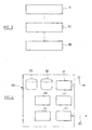
- the figure 2 is a functional representation of an exemplary architecture that can be used to realize the nodes N1 to N6.
- an optical layer here comprising a wavelength demultiplexer 12, an optical switching matrix 13 and a wavelength multiplexer 14, the optical switching matrix 13 allows to direct a wavelength channel entering either the outgoing fiber 15 to perform a transparent switching or to a regeneration-conversion unit 16, to perform regeneration or conversion-regeneration of the signal.
- the unit 16 comprises optical reception means 17 capable of operating at several wavelengths, preferably at all wavelengths of the grid used in the network, and optical transmission means 18 capable of operating at several frequencies. wavelengths, preferably at all wavelengths of the grid used in the network.
- the reception means 17 may comprise tunable filters or sets of fixed filters.
- the optical transmission means 18 may comprise wavelength tunable sources or sets of fixed sources.
- a node controller 20 controls the optical switching matrix 13 and the regeneration-conversion unit 16 according to the resources allocated to the connections. It is of course it is possible to connect more incoming fibers and / or outgoing fibers to such a node in a similar manner.
- optical layer of nodes N1 to N6 many other possibilities exist that do not need to be described here. Many other types of components may be employed, such as passive couplers, wavelength blockers, wavelength selective switches, and the like.
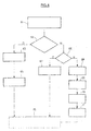
- the figure 4 is a functional representation of an embodiment of the node controller 20, usable in the nodes N1 to N6.
- a routing module 21 implements a link state routing protocol, for example OSPF-TE or IS-IS-TE, and exchanges routing messages 22 with the other nodes in accordance with this protocol, so as to disseminate messages. topology, connectivity and network link capacity information, according to the known technique.
- the node controller 20 includes a traffic engineering database 23 powered by the routing module 21 and in which this information is stored and dynamically updated.
- the node controller 20 includes a physical database 28 in which local physical parameters of the links and nodes of the network are stored.
- the physical database 28 is for example powered by the routing module 21 to update this information dynamically, for example from the measurements made by devices integrated in the nodes.
- the physical database 28 may be powered from a network management system, not shown.
- Various kinds of physical data can be provided in the database 28, so as to allow a predictive calculation of the degradation of the optical signals along a given transparent path in the network.
- parameters that can be used for this purpose are the cumulative chromatic dispersion per link, the OSNR degradation per link, the cumulative nonlinear phase per link, the link PMD, and so on.
- a signaling module 24 implements a signaling protocol, for example RSVP-TE, and exchanges signaling messages with the other nodes in accordance with this protocol, so as to manage the connections traversing the node, in particular the operations of establishing, modifying or deleting a connection.
- the traffic engineering database 23 is updated according to the connections established through the node, under the control of an admission control module 26, so as to dynamically record the state of occupying the optical interfaces of the node and the conversion-regeneration resources.
- these messages may be transported on the same links as the data traffic (" fiber ") or on dedicated dedicated links, on the same anal (“ in-band ”) or on separate dedicated channels.
- the traffic engineering database 23 permanently maintains detailed information on the state of the links adjacent to the node, ie the links connected to its incoming and outgoing optical interfaces. This detailed information notably includes the state of availability of each wavelength channel on these links. With respect to the non-adjacent links, the traffic engineering database 23 maintains less detailed status information because the routing protocol disseminates aggregated information to limit the volume of the exchanges. This aggregated information includes, for example, the bandwidth available on these links, but not the state of availability of each wavelength channel.
- the database 23 has been represented unitarily for the sake of simplicity, it is possible to structure this data in various ways, especially in the form of several interconnected data structures.
- wavelength channel can be applied absolutely or relatively.
- priority levels are allocated to connections and are used to allow or prohibit the reallocation of resources, eg. channels of wavelength, from one connection to another.
- resources eg. channels of wavelength
- the node controller 20 also has a tag management module 27 and a path calculation module 29 whose operation will be described below.
- a step of determining the spatial path 51 and a step of taking into account the physical degradations 52 are performed at least partially before a signaling step 53 used in particular to perform the allocation of wavelengths. This way of proceeding is particularly advantageous in cases where the determination of the spatial path and the taking into account of physical degradations from relatively centralized information and the allocation of wavelengths from distributed information are carried out. in the knots.
- Step 51 consists in determining a path descriptor comprising a sequence of addresses of nodes or groups of nodes to be traversed to reach the destination. This sequence can be determined strictly or partially. A partially determined sequence has at least one loose hop.
- the address sequence is represented under the form of an Explicit Route Object (ERO) object, as described in IETF RFCs 3209 and 3477.
- ERO Explicit Route Object
- other formats may be used to represent the path descriptor.
- Step 52 consists in determining the node (s) of the sequence at which a regeneration of the optical signal is necessary and, if necessary, to produce regeneration instructions associated with this or these node (s).
- the regeneration instructions associated with a node are represented as an attribute of a sub-object representing the node in question. the aforementioned PRO object. This attribute may for example be coded on one or more bits of the sub-object, for example in an Interface ID field.
- steps 51 and 52 are performed by a controller of the upstream end node of the connection made in accordance with the figure 4 .
- the path calculation module 29 performs steps 51 and 52 by exploiting the topology and physics data stored in the bases 23 and 28.
- the signaling module 24 starts the signaling step 53 by issuing a connection request comprising a descriptor of the determined connection path, the associated regeneration instructions, if any, and a wavelength allocation offer.
- the signaling phase thus triggered serves in particular to identify a wavelength channel that can be used all along the path of the new connection or wavelength channels that can be used on successive segments of said path by performing a or several conversion-regeneration operations. To determine this or these channels, the nodes implement a distributed method which will now be described.
- the signaling method is based on the RSVP-TE protocol and the wavelength allocation on the use of the LABEL SET object in accordance with the principles described in RFC 3471 of the IETF.
- the upstream end node of the connection to be established namely here N1
- generates a connection request in the form of a PATH message containing, in other objects, regeneration instructions specifying the node or nodes of the path of the connection.
- the regeneration instructions are here encoded in an ERO object specifying strictly or partially the path of the connection to be established.
- the LABEL SET object is represented by parentheses and the ERO object by a rectangular frame.
- this PATH message is transmitted from node to node to the downstream end node, namely here N6.
- the content of the PATH message can be modified by each successive node.
- the LABEL SET object is processed by the tag management module 27 so as to produce, from the SET LABEL received from the upstream neighbor node, an updated LABEL SET to be transmitted to the downstream neighbor node.
- the downstream end node selects one of the channels identified in the LABEL SET and the copy in a LABEL object, also represented by parentheses, which it retransmits upstream in a RESV message.
- the RESV message is transmitted from node to node to the upstream end node to proceed, jump by jump, to the allocation of wavelengths.
- each successive node can modify the LABEL object by restricting itself to the channels proposed in the LABEL SET that it has received.
- step 61 the PATCH message comprising in particular the ERO and LABEL SET objects is received from the upstream neighbor node and sequenced.
- step 62 the presence of a regeneration instruction associated with the node in which the process is taking place is sought. If such an instruction is present, the method proceeds to step 63, otherwise to step 66.
- step 66 a wavelength continuity condition is evaluated. For this, the content of the LABEL SET which has been received from the upstream neighbor node is read to identify the wavelength channels designated in this LABEL SET, then the database 23 is consulted to determine which channels, among the channels designated in the received SET LABEL, are available on the adjacent downstream link, ie available to carry the new connection to the downstream neighbor node in accordance with the condition of continuity. If it exists, the method proceeds to step 67 in which a new LABEL SET designating all or some of these available channels is generated for transmission to the downstream neighbor node.
- step 66 if it turns out that none of the channels designated in the received LABEL SET are available on the downstream adjacent link (s), the need is detected to perform a length conversion-regeneration. wave from one or more of the designated channels in the received LABEL SET.
- step 68 the database 23 is consulted to determine the wavelength channel (s) accessible via this conversion and available to carry the new connection towards the downstream neighbor node. The method then proceeds to step 69 in which a new LABEL SET designating all or some of these channels is generated for transmission to the downstream neighbor node. Accessible via conversion means that the node has the hardware capabilities to perform the corresponding wavelength conversion from at least one of the designated channels in the received LABEL SET.
- Step 70 consists in estimating physical impairments of the optical signal along the portion of the connection path located downstream of the node and determining accordingly whether one or more regenerations of the optical signal are required at one or more nodes. downstream and, if so, by which nodes these regenerations must be carried out.
- This step can be performed using the physical parameters stored in the physical database 28, similarly to the above-mentioned step 52.
- Step 71 is to update the regeneration instructions received from the upstream neighbor node to comply with the determinations of step 70. Accordingly, regeneration instructions may be deleted and / or added and an object Modified ERO is thus generated.
- step 63 the decision is made, according to the detected instruction, to perform wavelength conversion-regeneration from one or more of the designated channels in the received LABEL SET.
- the database 23 is consulted to determine the wavelength channel (s) accessible via this conversion and available to carry the new connection towards the downstream neighbor node.
- the process then proceeds to step 64 in which a new LABEL SET designating all or some of these channels is generated to be transmitted to the downstream neighbor node.
- step 65 the PATH message is transmitted to the downstream neighbor node with the new LABEL SET object and possibly modified ERO object, to be processed similarly by the downstream node.
- this method is implemented by nodes conforming to the figure 4 .
- Steps 61, 62 and 65 are performed by the signaling module 24.
- Steps 63, 64 and 66 to 69 are performed by the tag management module 27.
- Steps 70 and 71 are performed by the path calculation module 29.
- a centralized computing device 100 shown schematically in FIG. figure 1 may be provided to perform at least some of steps 51, 52, 70 and 71 in place of the node controllers.
- the device 100 is each time interrogated by a node in need of the information corresponding to one of these steps and transmits a response to this node.
- the centralized computing device 100 is a PCE capable of communicating with the nodes by a PCEP protocol, as described in RFC 4655 of the IETF and other documents of the PCE working group.
- the allocation of the wavelengths is finally achieved by means of a single message exchange between the two ends of the connection and with only two conversions-regenerations, which is an optimum given the assumptions made on the physical degradations. If we short-circuited the stages 70 and 71 at the node N2, it is easy to conceive that one would end up on the other hand with a total of three conversions-regenerations, namely in N2, then with the two points initially envisaged N3 and N5.
- step 62 bypassed step 62 and passed through step 66 at the N4 node, it is easy to conceive that it would lead on the other hand to achieve additional conversion-regeneration at node N5 because of the unavailability of channel L3 on link 5, a total of three conversions-regenerations in N2, N4 and N5.
- steps 62 to 64 may be provided without steps 70 and 71.
- steps 66 to 71 may be provided without steps 62 to 64.
- step 70 comprises calculating a modified spatial path between the current node and the downstream end node and determining the physical degradations along this modified path.
- the object ERO is modified to reflect the new sequence of nodes thus calculated between the current node and the downstream end node and, where appropriate, the regeneration instructions associated with these nodes.
- each node processes the object ERO to retransmit every time that the information relating to the downstream portion of the path of the connection, which limits the volume of the signaling messages.
- this restriction is not mandatory.
- each node retransmits the signaling message with also the regeneration instructions reflecting the regenerations performed on the upstream portion of the path of the connection and at the level of said node, which notably allows the downstream end node to know all regeneration points of the connection.
- wavelength conversion or simply conversion refers to the modification of the carrier wavelength used to carry a data signal.
- conversion-regeneration the following steps can be followed: reception of the incoming optical signal, electronic demodulation of the transported data signal, and use of the data signal to modulate an optical signal at a different wavelength.
- a part of the demodulated data for example corresponding to control data, may be modified during the conversion-regeneration operation.
- the transmission direction of the allocation offer corresponds to the direction of transmission of the data in the connection.
- this is not mandatory.
- the process of figure 4 can be adapted to handle a UPSTREAM LABEL SET object, which is an allocation offer for the upstream direction of a bidirectional LSP.
- wavelength allocation methods in which an allocation offer travels from node to node while being updated based on locally available information are particularly usable in any optical network where the detailed information as to the state of occupation of each link, including the identity of the free channels, is only available at a local level.
Abstract
Description
L'invention se rapporte au domaine des réseaux de communication optiques utilisant le multiplexage en longueurs d'onde (WDM) et capables d'établir des connexions transparentes ou photoniques, notamment aux réseaux à plan de contrôle GMPLS.The invention relates to the field of optical communication networks using wavelength division multiplexing (WDM) and capable of establishing transparent or photonic connections, in particular to GMPLS control plane networks.
Dans un réseau optique, réaliser la transmission d'un signal optique de manière transparente au niveau d'un noeud de commutation, c'est-à-dire sans conversion du signal de données vers le domaine électronique, permet de réduire l'utilisation des transpondeurs optiques et la consommation d'énergie. Il y a donc un avantage économique à réaliser des connexions transparentes lorsque cela est possible. Pour cela, il est nécessaire de disposer d'une méthode d'allocation de longueur d'onde qui permette de trouver un canal de longueur d'onde disponible sur le chemin de la connexion. Par ailleurs, des dégradations physiques des signaux optiques au cours de la propagation imposent des limites de portée des connexions transparentes et rendent nécessaire d'effectuer une régénération du signal optique pour qu'une connexion puisse atteindre une destination située au-delà de ces limites de portée.In an optical network, transmitting an optical signal transparently at a switching node, i.e. without converting the data signal to the electronic domain, reduces the use of optical transponders and power consumption. There is therefore an economic advantage to making transparent connections where possible. For this, it is necessary to have a wavelength allocation method which makes it possible to find an available wavelength channel on the path of the connection. Furthermore, physical impairments of the optical signals during the propagation impose limits of scope of the transparent connections and make it necessary to carry out a regeneration of the optical signal so that a connection can reach a destination situated beyond these limits. scope.
Dans le contexte des réseaux à plan de contrôle distribué de type Generalized Multi Protocol Label Switching (GMPLS), par exemple dans le document
Un but de l'invention est de proposer des méthodes pour établir des connexions dans un réseau optique en tenant compte de la disponibilité des canaux de longueur d'onde et des dégradations physiques.An object of the invention is to provide methods for establishing connections in an optical network taking into account the availability of wavelength channels and physical impairments.
Selon un mode de réalisation, l'invention fournit un procédé de signalisation pour établir une connexion le long d'un chemin dans un réseau optique, comprenant l'étape consistant à recevoir au niveau d'un noeud capable de conversion-régénération un message de signalisation comportant, d'une part, un premier ensemble d'identifiants de canaux de longueur d'onde représentant au moins un canal de longueur d'onde susceptible d'être alloué à ladite connexion entre ledit noeud capable de conversion-régénération et un noeud voisin amont et, d'autre part, des instructions de régénération associées à au moins un noeud du chemin de la connexion et destinées à provoquer la régénération d'un signal optique de la connexion par ledit ou chaque noeud associé.According to one embodiment, the invention provides a signaling method for establishing a connection along a path in an optical network, comprising the step of receiving at a node capable of conversion-regeneration a message of signaling comprising, on the one hand, a first set of wavelength channel identifiers representing at least one wavelength channel likely to be allocated to said connection between said conversion-regeneration capable node and a node upstream neighbor and, secondly, regeneration instructions associated with at least one node of the path of the connection and intended to cause the regeneration of an optical signal of the connection by said or each associated node.
Selon d'autres modes de réalisation avantageux, ce procédé peut présenter une ou plusieurs des caractéristiques additionnelles suivantes.According to other advantageous embodiments, this method may have one or more of the following additional features.
Selon un mode de réalisation particulier, le procédé comporte en outre les étapes consistant à,
détecter un besoin d'effectuer une conversion-régénération dudit signal optique de la connexion au niveau du noeud capable de conversion-régénération en fonction d'un état de disponibilité dudit au moins un canal de longueur d'onde sur une portion aval du chemin de la connexion,
en réponse à ladite détection, déterminer s'il existe un besoin d'effectuer une régénération dudit signal optique de la connexion au niveau d'au moins un noeud situé en aval sur le chemin de la connexion en fonction d'une dégradation physique estimée dudit signal optique,
en fonction du besoin déterminé, modifier des instructions de régénération associées audit au moins un noeud situé en aval, et
transmettre à un noeud voisin aval un message de signalisation comportant, d'une part, un deuxième ensemble d'identifiants de canaux de longueur d'onde représentant au moins un canal de longueur d'onde susceptible d'être alloué à ladite connexion entre ledit noeud capable de conversion-régénération et ledit noeud voisin aval et, d'autre part, lesdites instructions de régénération modifiées.According to a particular embodiment, the method further comprises the steps of
detecting a need to convert-regenerate said optical signal of the connection at the node capable of conversion-regeneration according to a state of availability of said at least one wavelength channel on a downstream portion of the path of the connection,
in response to said detection, determining whether there is a need to regenerate said optical signal of the connection at at least one node downstream on the connection path based on an estimated physical degradation of said connection optical signal,
according to the determined need, modifying regeneration instructions associated with said at least one node located downstream, and
transmitting to a downstream neighbor node a signaling message comprising, on the one hand, a second set of wavelength channel identifiers representing at least one wavelength channel likely to be allocated to said connection between said node capable of conversion-regeneration and said downstream neighboring node and, on the other hand, said modified regeneration instructions.
Selon, un mode de réalisation particulier, l'étape de modification comporte la suppression d'une instruction de régénération associée à un noeud situé en aval pour lequel ledit besoin est déterminé ne pas exister et/ou l'adjonction d'une instruction de régénération associée à un noeud situé en aval pour lequel ledit besoin est déterminé exister,According to a particular embodiment, the modification step comprises the deletion of a regeneration instruction associated with a downstream node for which said need is determined not to exist and / or the addition of a regeneration instruction. associated with a downstream node for which said need is determined to exist,
Selon un mode de réalisation particulier, le procédé comporte en outre l'étape consistant à accéder à une base de données comportant des paramètres physiques des liens du réseau pour estimer ladite dégradation physique du signal optique au niveau dudit au moins un noeud situé en aval.According to a particular embodiment, the method further comprises the step of accessing a database comprising physical parameters of the links of the network to estimate said physical degradation of the optical signal at said at least one node downstream.
Selon un mode de réalisation particulier, le procédé comporte en outre l'étape consistant à collecter lesdits paramètres physiques des liens au moyen d'un protocole de routage à état des liens.According to a particular embodiment, the method further comprises the step of collecting said physical parameters of the links by means of a link state routing protocol.
Selon un mode de réalisation particulier, ledit message de signalisation reçu comporte un descripteur de chemin comprenant des identifiants d'une séquence de noeuds situés sur le chemin de la connexion.According to a particular embodiment, said received signaling message comprises a path descriptor comprising identifiers of a sequence of nodes located on the path of the connection.
Avantageusement, lesdites instructions de régénération sont incluses dans ledit descripteur de chemin. Une telle représentation des instructions de régénération facilite la sémantique d'association entre les instructions et les noeuds. Toutefois de nombreuses autres possibilités existent quant à la représentation des instructions de régénération.Advantageously, said regeneration instructions are included in said path descriptor. Such a representation of the regeneration instructions facilitates the association semantics between the instructions and the nodes. However, many other possibilities exist for the representation of the regeneration instructions.
Selon un mode de réalisation particulier, le procédé comporte en outre les étapes consistant à accéder à une base de données de topologie du réseau pour déterminer une séquence de noeuds modifiée entre ledit noeud capable de conversion-régénération et un noeud de destination de la connexion et à transmettre un descripteur de chemin modifié de manière correspondante dans le message de signalisation transmis audit noeud voisin aval.According to a particular embodiment, the method further comprises the steps of accessing a network topology database to determine a modified node sequence between said conversion-regeneration capable node and a destination node of the connection and transmitting a corresponding modified path descriptor in the signaling message transmitted to said downstream neighbor node.
Selon un mode de réalisation préféré, la connexion est un chemin à commutation d'étiquette d'un réseau GMPLS. Selon un mode de réalisation particulier, les messages de signalisation sont conformes au protocole RSVP-TE. Selon un mode de réalisation particulier, les ensembles d'identifiants de canaux de longueur d'onde consistent en des objets LABEL SET ou UPSTREAM LABEL SET dudit protocole.According to a preferred embodiment, the connection is a tag-switched path of a GMPLS network. According to a particular embodiment, the signaling messages are in accordance with the RSVP-TE protocol. According to a particular embodiment, the sets of wavelength channel identifiers consist of LABEL SET or UPSTREAM LABEL SET objects of said protocol.
Selon un autre mode de réalisation, l'invention fournit également un programme d'ordinateur comportant des codes d'instruction aptes à être lus ou écrits sur un support et aptes à être exécutés par un ordinateur pour effectuer toutes les étapes du procédé précité.According to another embodiment, the invention also provides a computer program comprising instruction codes that can be read or written on a support and that can be executed by a computer to carry out all the steps of the aforementioned method.
Selon un autre mode de réalisation, l'invention fournit également un dispositif de commande pour un noeud de commutation optique capable de conversion-régénération, ledit dispositif de commande comportant des moyens pour effectuer toutes les étapes du procédé précité.According to another embodiment, the invention also provides a control device for an optical switching node capable of conversion-regeneration, said control device comprising means for performing all the steps of the aforementioned method.
L'invention fournit également un procédé de signalisation pour établir une connexion le long d'un chemin dans un réseau optique, comprenant les étapes consistant à :
- recevoir au niveau d'un noeud capable de conversion-régénération un message de signalisation comportant, d'une port, un premier ensemble d'identifiants de canaux de longueur d'onde représentant au moins un canal de longueur d'onde susceptible d'être alloué à ladite connexion entre ledit noeud capable de conversion-régénération et un noeud voisin amont et, d'autre part, des instructions de régénération associées à au moins un noeud du chemin de la connexion et destinées à provoquer la régénération d'un signal optique de la connexion par ledit ou chaque noeud associé, détecter des instructions de régénération associées audit noeud capable de conversion-régénération,
- en réponse à ladite détection, déterminer au moins un canal de longueur d'onde susceptible d'être produit par des moyens de conversion-régénération dudit noeud et disponible pour être alloué à ladite connexion entre ledit noeud capable de conversion-régénération et ledit noeud voisin aval,
- produire un deuxième ensemble d'identifiants de canaux de longueur d'onde, ledit deuxième ensemble d'identifiants de canaux de longueur d'onde représentant ledit au moins un canal de longueur d'onde déterminé à l'étape précédente, et
- transmettre audit noeud voisin aval un message de signalisation comportant ledit deuxième ensemble d'identifiants de canaux de longueur d'onde et lesdites instructions de régénération reçues.
- receiving at a node capable of conversion-regeneration a signaling message comprising, from a port, a first set of wavelength channel identifiers representing at least one wavelength channel likely to be allocated to said connection between said conversion-regeneration capable node and an upstream neighbor node and, on the other hand, regeneration instructions associated with at least one node of the connection path and for causing the regeneration of an optical signal the connection by said or each associated node, detecting regeneration instructions associated with said node capable of conversion-regeneration,
- in response to said detection, determining at least one wavelength channel likely to be produced by conversion-regeneration means of said node and available to be allocated to said connection between said conversion-regeneration capable node and said neighbor node downstream,
- producing a second set of wavelength channel identifiers, said second set of wavelength channel identifiers representing said at least one wavelength channel determined in the previous step, and
- transmitting to said downstream neighbor node a signaling message comprising said second set of wavelength channel identifiers and said regeneration instructions received.
De préférence, ledit deuxième ensemble d'identifiants de canaux de longueur d'onde représente au moins un canal de longueur d'onde différent dudit au moins un canal de longueur d'onde représenté par le premier ensemble d'identifiants.Preferably, said second set of wavelength channel identifiers represents at least one channel of wavelength different from said at least one least one wavelength channel represented by the first set of identifiers.
Selon un autre mode de réalisation, l'invention fournit également un programme d'ordinateur comportant des codes d'instruction aptes à être lus ou écrits sur un support et aptes à être exécutés par un ordinateur pour effectuer toutes les étapes du procédé précité.According to another embodiment, the invention also provides a computer program comprising instruction codes that can be read or written on a support and that can be executed by a computer to carry out all the steps of the aforementioned method.
Selon un autre mode de réalisation, l'invention fournit également un dispositif de commande pour un noeud de commutation optique capable de conversion-régénération, ledit dispositif de commande comportant des moyens pour effectuer toutes les étapes du procédé précité.According to another embodiment, the invention also provides a control device for an optical switching node capable of conversion-regeneration, said control device comprising means for performing all the steps of the aforementioned method.
Les termes « amont » et « aval font référence au sens de transmission des messages de signalisation et sont indépendants de toute référence au sens des signaux optiques devant être transportés par la connexion, qui peut être unidirectionnelle ou bidirectionnelle.The terms "upstream" and "downstream" refer to the direction of transmission of the signaling messages and are independent of any reference to the direction of the optical signals to be transported by the connection, which may be unidirectional or bidirectional.
L'invention part du constat qu'il existe de nombreuses architectures de noeuds de commutation optiques dans lesquelles la conversion de longueur d'onde d'un signal optique est effectuée par l'intermédiaire d'une conversion optique/électronique/optique (O/E/O), à savoir en démodulant le signal reçu à une première longueur d'onde puis en modulant un signal optique à une seconde longueur d'onde avec les données ainsi obtenues. Ainsi, dans une conversion de ce type, le signal optique est complètement régénéré en même temps que sa longueur d'onde porteuse est modifiée. On appelle conversion-régénération ce type d'opération. Réciproquement, il existe de nombreuses architectures de noeuds de commutation optiques dans lesquelles les transpondeurs prévus pour régénérer les signaux optiques sont capables de transmettre un signal régénéré à une longueur d'onde différente du signal reçu, permettant ainsi de réaliser une conversion-régénération sensiblement sans coût supplémentaire par rapport à une simple régénération. Certains aspects de l'invention sont fondés sur l'idée de contrôler l'utilisation des transpondeurs O/E/O le long du chemin d'une connexion de façon à effectuer de manière synergique les opérations de conversion de longueur d'onde requises, par exemple en raison de la contention sur les canaux de longueur d'onde, et les opérations de régénération des signaux requises, par exemple en raison des dégradations physiques.The invention is based on the observation that there are many architectures of optical switching nodes in which the wavelength conversion of an optical signal is carried out via an optical / electronic / optical conversion (O / I / O), namely by demodulating the signal received at a first wavelength and then modulating an optical signal at a second wavelength with the data thus obtained. Thus, in a conversion of this type, the optical signal is completely regenerated at the same time as its carrier wavelength is changed. This type of operation is called conversion-regeneration. Conversely, there are many architectures of optical switching nodes in which the transponders provided for regenerating the optical signals are capable of transmitting a regenerated signal at a wavelength different from the received signal, thus enabling conversion-regeneration to be substantially substantially additional cost compared to a simple regeneration. Aspects of the invention are based on the idea of controlling the use of O / E / O transponders along the path of a connection so as to synergistically perform the required wavelength conversion operations. for example because of the contention on the wavelength channels, and the regeneration operations of the required signals, for example due to physical degradations.
Une idée à la base de l'invention est de véhiculer dans un même message de signalisation une offre d'allocation de longueur d'onde destinée à permettre aux noeuds de déterminer localement si une commutation transparente est possible ou si une conversion de longueur d'onde est nécessaire, et des instructions de régénération destinées à provoquer la régénération du signal optique de la connexion par certains noeuds. Une telle méthode de signalisation permet aux noeuds de traiter de manière coordonnée l'allocation des longueurs d'onde et les besoins de régénération des signaux d'une manière qui privilégie globalement les commutations transparentes dans le domaine optique.An idea underlying the invention is to convey in the same signaling message a wavelength allocation offer intended to allow the nodes to determine locally whether transparent switching is possible or whether a length conversion of wave is required, and regeneration instructions to cause the regeneration of the optical signal of the connection by some nodes. Such a signaling method allows nodes to coordinately deal with wavelength allocation and signal regeneration requirements in a manner that generally favors transparent switching in the optical domain.
L'invention sera mieux comprise, et d'autres buts, détails, caractéristiques et avantages de celle-ci apparaîtront plus clairement au cours de la description suivante de plusieurs modes de réalisation particuliers de l'invention, donnés uniquement à titre illustratif et non limitatif, en référence aux dessins annexés. Sur ces dessins :
- La
figure 1 est une représentation schématique fonctionnelle d'un réseau optique hybride dans lequel une connexion peut être établie. - La
figure 2 est une représentation schématique fonctionnelle d'un noeud de commutation pouvant être utilisé dans le réseau de lafigure 1 . - La
figure 3 est un diagramme d'étape représentant un procécé d'établissement d'une connexion partiellement transparente pouvant être mis en oeuvre dans le réseau de lafigure 1 . - La
figure 4 est une représentation schématique fonctionnelle d'un mode de réalisation de contrôleur de noeud pouvant être utilisé dans le réseau de lafigure 1 . - La
figure 5 est un diagramme représentant un mode de réalisation d'une étape de signalisation pouvant être utilisé dans le procédé de lafigure 3 . - La
figure 6 est un diagramme d'étape représentant un procédé de traitement de la signalisation pouvant être mis en oeuvre par le contrôleur de noeud de lafigure 4 .
- The
figure 1 is a functional schematic representation of a hybrid optical network in which a connection can be established. - The
figure 2 is a functional schematic representation of a switching node that can be used in the network of thefigure 1 . - The
figure 3 is a step diagram representing a process for establishing a partially transparent connection that can be implemented in the network of thefigure 1 . - The
figure 4 is a functional schematic representation of a node controller embodiment that can be used in the network of thefigure 1 . - The
figure 5 is a diagram showing an embodiment of a signaling step that can be used in the method of thefigure 3 . - The
figure 6 is a step diagram showing a signal processing method that can be implemented by the node controller of thefigure 4 .
En référence à la
Pour contrôler le réseau 10, une pile protocolaire GMPLS est déployée au niveau de chaque noeud. Les noeuds sont donc capables d'établir des connexions sous la forme de chemins à commutation d'étiquette (LSP pour Label-switched path). En particulier, des étiquettes généralisées de type longueur d'onde (LSP Encoding Type = Lambda) sont utilisées pour signaliser des connexions photoniques à la granularité d'un canal de longueur d'onde.To control the
Les noeuds du réseau 10 peuvent être identiques ou différents les uns des autres. La
En ce qui concerne la couche optique des noeuds N1 à N6, de nombreuses autres possibilités existent qui n'ont pas besoin d'être décrites ici. De nombreux autres types de composants peuvent être employés, par exemple des coupleurs passifs, des bloqueurs de longueurs d'ondes, des commutateurs à sélection de longueur d'onde (wavelength selective switch), etc.With regard to the optical layer of nodes N1 to N6, many other possibilities exist that do not need to be described here. Many other types of components may be employed, such as passive couplers, wavelength blockers, wavelength selective switches, and the like.
La
Le contrôleur de noeud 20 comporte une base de données physiques 28 dans laquelle sont stockés des paramètres physiques locaux des liens et des noeuds du réseau. La base de données physiques 28 est par exemple alimentée par le module de routage 21 pour mettre à jour ces informations de manière dynamique, par exemple à partir des mesures effectuées par des dispositifs intégrés dans les noeuds. En variante, la base de données physiques 28 peut être alimentée à partir d'un système de gestion du réseau, non représenté. Différentes sortes de données physiques peuvent être prévues dans la base de données 28, de façon à permettre un calcul prédictif de la dégradation des signaux optiques le long d'un chemin transparent donné dans le réseau. Par exemple, des paramètres utilisables dans ce but sont la dispersion chromatique cumulée par lien, la dégradation d'OSNR par lien, la phase non-linéaire cumulée par lien, la PMD du lien, etc. Il est aussi possible de stocker des paramètres plus descriptifs du lien tels que les caractéristiques de chaque section d'amplification avec leurs contributions en bruit et leurs atténuations. Ces paramètres étant pour partie dépendants de la longueur d'onde, les voleurs relatives au paire cas peuvent être retenues, ou des valeurs moyennes, ou des tableaux de voleurs propres à choque longueur d'onde. Bien qu'on ait représenté la base de données 28 de manière unitaire par mesure de simplicité, il est possible de structurer ces données de différentes manières, notamment sous la forme de plusieurs structures de données interconnectées.The
Un module de signalisation 24 met en oeuvre un protocole de signalisation, par exemple RSVP-TE, et échange des messages de signalisation 25 avec les autres noeuds conformément à ce protocole, de manière à gérer les connexions traversant le noeud, notamment les opérations d'établissement, de modification ou de suppression d'une connexion. La base de données d'ingénierie de trafic 23 est mise à jour en fonction des connexions établies à travers le noeud, sous le contrôle d'un module de contrôle d'admission 26, de manière à enregistrer de manière dynamique l'état d'occupation des interfaces optiques du noeud et des ressources de conversion-régénération.A
Il existe plusieurs possibilités pour réaliser le transport des messages de contrôle, notamment les messages de routage 22 et messages de signalisation 25 dans le réseau 10. Par exemple, ces messages peuvent être transportés sur les mêmes liens que le trafic de données (« in-fiber ») ou sur des liens dédiés distincts, sur les mêmes anaux (« in-band ») ou sur des canaux dédiés distincts.There are several possibilities for carrying out the transport of the control messages, in particular the
Ainsi, en fonction des informations obtenues à travers le module de signalisation 24 et du module de routage 21, la base de données d'ingénierie de trafic 23 maintient en permanence des informations détaillées sur l'état des liens adjacents au noeud, i.e. les liens connectés à ses interfaces optiques entrantes et sortantes. Ces informations détaillées comportent notamment l'état de disponibilité de chaque canal de longueur d'onde sur ces liens. En ce qui concerne les liens non adjacents, la base de données d'ingénierie de trafic 23 maintient des informations d'état moins détaillées car le protocole de routage dissémine des informations agrégées afin de limiter le volume des échanges. Ces informations agrégées comportent par exemple la bande passante disponible sur ces liens, mais non l'état de disponibilité de chaque canal de longueur d'onde. Bien qu'on ait représenté la base de données 23 de manière unitaire par mesure de simplicité, il est possible de structurer ces données de différentes manières, notamment sous la forme de plusieurs structures de données interconnectées.Thus, based on the information obtained through the
La notion de disponibilité d'un canal de longueur d'onde peut être appliquée de manière absolue ou de manière relative. Dans un mode de réalisation, des niveaux de priorité sont alloués aux connexions et sont utilisés pour permettre ou interdire la réaffectation des ressources, par ex. des canaux de longueur d'onde, d'une connexion à une autre. Dans ce cas, un canal de longueur d'onde occupé par une connexion est considéré disponible pour l'établissement d'une connexion de priorité supérieure mais indisponible pour l'établissement d'une connexion de priorité inférieure ou égale.The notion of availability of a wavelength channel can be applied absolutely or relatively. In one embodiment, priority levels are allocated to connections and are used to allow or prohibit the reallocation of resources, eg. channels of wavelength, from one connection to another. In this case, a wavelength channel occupied by a connection is considered available for establishing a higher priority connection but unavailable for establishing a connection of lower or equal priority.
Le contrôleur de noeud 20 compte aussi un module de gestion des étiquettes 27 et un module de calcul de chemin 29 dont le fonctionnement sera décrit plus bas.The
Pour procéder à l'établissement d'un nouveau LSP de type Lambda entre un noeud d'extrémité amont et un noeud d'extrémité aval donnés, par exemple un LSP ayant un débit égal au débit d'un canal de longueur d'onde entre le noeud N1 et le noeud N6, il existe essentiellement trois problématiques à résoudre : la détermination d'un chemin spatial, autrement dit la détermination des noeuds et des liens qui vont être utilisés, l'allocation des longueurs d'onde, autrement dit la détermination du ou des canaux qui vont être utilisés sur ces liens, et la prise en compte des dégradations physiques du signal optique, autrement dit la détermination des éventuelles opérations de régénération nécessaires en certains points du chemin pour obtenir un signal de la qualité souhaitée au niveau de la destination.To proceed with the establishment of a new Lambda-type LSP between an upstream end node and a given downstream end node, for example an LSP having a rate equal to the throughput of a channel of wavelength between the node N1 and the node N6, there are essentially three problems to be solved: the determination of a spatial path, in other words the determination of the nodes and links that will be used, the allocation of the wavelengths, in other words the determination of the channel or channels that will be used on these links, and taking into account the physical degradation of the optical signal, in other words the determination of any necessary regeneration operations at certain points of the path to obtain a signal of the desired quality at the level of the signal. of the destination.
Dans un mode de réalisation d'un procédé d'établissement d'une connexion représenté sur la
L'étape 51 consiste à déterminer un descripteur de chemin comportant une séquence d'adresses de noeuds ou de groupes de noeuds devant être traversés pour atteindre la destination. Cette séquence peut être déterminée strictement ou partialement. Une séquence partiellement déterminée comporte au moins un saut flottant (loose hop). Dans un mode de réalisation adapté à l'utilisation d'une signalisation par le protocole RSVP-TE, la séquence d'adresse est représentée sous la forme d'un objet Explicit Route Object (ERO), tel que décrit dans les RFC 3209 et 3477 de l'IETF. En variante, d'autres formats peuvent être utilisés pour représenter le descripteur de chemin.
L'étape 52 consiste à déterminer le ou les noeud(s) de la séquence au niveau desquels une régénération du signal optique est nécessaire et, le cas échéant, à produire des instructions de régénération associées à ce ou ces noeud(s). Dans un mode de réalisation adopté à l'utilisation d'une signalisation par le protocole RSVP-TE, les instructions de régénération associées à un noeud sont représentées sous la forme d'un attribut d'un sous-objet représentant le noeud en question dans l'objet PRO précité. Cet attribut peut être par exemple codé sur un ou plusieurs bits du sous-objet, par exemple dans un champ Interface ID.
Dans un mode de réalisation, les étapes 51 et 52 sont effectuées par un contrôleur du noeud d'extrémité amont de la connexion réalisé conformément à la
Puis le module de signalisation 24 débute l'étape de signalisation 53 en émettant une requête de connexion comportant un descripteur du chemin de connexion déterminé, les instructions de régénération associées, le cas échéant, et une offre d'allocation de longueurs d'onde. La phase de signalisation ainsi déclenchée sert notamment à identifier un canal de longueur d'onde qui puisse être utilisé tout le long du chemin de la nouvelle connexion ou des canaux de longueur d'onde pouvant être utilisés sur des segments successifs dudit chemin en effectuant une ou plusieurs opérations de conversion-régénération. Pour déterminer ce ou ces canaux, les noeuds mettent en oeuvre un procédé distribué qui va maintenant être décrit.Then, the
Dans un mode de réalisation illustré par les
Dans une première phase de signalisation 30, ce message PATH est transmis de noeud en noeud vers le noeud d'extrémité aval, à savoir ici N6. Au cours de cette transmission, le contenu du message PATH peut être modifié par chaque noeud successif. En particulier, l'objet LABEL SET est traité par le module de gestion des étiquettes 27 de manière à produire, à partir du LABEL SET reçu depuis le noeud voisin amont, un LABEL SET actualisé destiné à être transmis au noeud voisin aval. Lorsque le noeud d'extrémité aval reçoit le message PATH, il sélectionne un canal parmi ceux identifiés dans le LABEL SET et le copie dans un objet LABEL, représenté également par des parenthèses, qu'il retransmet vers l'amont dans un message RESV. Dans une deuxième phase de signalisation 40, le message RESV est transmis de noeud en noeud vers le noeud d'extrémité amont pour procéder, saut par saut, à l'allocation des longueurs d'onde. Au cours de cette transmission, chaque noeud successif peut modifier l'objet LABEL en se restreignant aux canaux proposés dans le LABEL SET qu'il a reçu.In a
En référence à la
A l'étape 61, le message PATCH comportant notamment les objets ERO et LABEL SET est reçu depuis le noeud voisin amont et séquencé.In
A l'étape 62, la présence d'une instruction de régénération associée au noeud dans lequel le procédé se déroule est recherchée. Si une telle instruction est présente, le procédé passe à l'étape 63, sinon à l'étape 66.In
A l'étape 66, une condition de continuité de longueur d'onde est évaluée. Pour cela, le contenu du LABEL SET qui a été reçu depuis le noeud voisin amont est lu pour identifier les canaux de longueur d'onde désignés dans ce LABEL SET, puis la base de données 23 est consultée pour déterminer quels canaux, parmi les canaux désignés dnns le LABEL SET reçu, sont disponibles sur le lien adjacent aval, c'est-à-dire disponibles pour porter la nouvelle connexion en direction du noeud voisin aval en respectant la condition de continuité. S'il en existe, le procédé passe à l'étape 67 dans laquelle un nouveau LABEL SET désignant tous ou certains de ces canaux disponibles est généré pour être transmis au noeud voisin aval.In
A l'étape 66, s'il s'avère qu'aucun des canaux désignés dans le LABEL SET reçu n'est disponible sur le ou les liens adjacents aval, le besoin est détecté d'effectuer une conversion-régénération de longueur d'onde à partir d'un ou plusieurs des canaux désignés dans le LABEL SET reçu. A l'étape 68, la base de données 23 est consultée pour déterminer le ou les canaux de longueur d'onde accessibles via cette conversion et disponibles pour porter la nouvelle connexion en direction du noeud voisin aval. Le procédé passe alors à l'étape 69 dans laquelle un nouveau LABEL SET désignant tous ou certains de ces canaux est généré pour être transmis au noeud voisin aval. Accessible via conversion signifie que le noeud dispose des capacités matérielles pour effectuer la conversion de longueur d'onde correspondante depuis au moins un des canaux désignés dans le LABEL SET reçu.In
En conséquence de la décision d'effectuer une conversion-régénération du signal au niveau du noeud, des étapes 70 et 71 sont aussi effectuées. L'étape 70 consiste à estimer des dégradations physiques du signal optique le long de la portion du chemin de connexion située en aval du noeud et à déterminer en conséquence si une ou plusieurs régénérations du signal optique sont nécessaires au niveau d'un ou plusieurs noeuds aval et, le cas échéant, par quels noeuds ces régénérations doivent être effectuées. Cette étape peut être effectuée à l'aide des paramètres physiques stockés dans la base de données physiques 28, similairement à l'étape 52 précitée. L'étape 71 consiste à mettre à jour les instructions de régénération reçues depuis le noeud voisin amont pour les mettre en conformité avec les déterminations de l'étape 70. En conséquence, des instructions de régénération peuvent être supprimées et/ou ajoutées et un objet ERO modifié est ainsi généré.As a consequence of the decision to convert-regenerate the signal at the node, steps 70 and 71 are also performed.
A l'étape 63, la décision est prise, en application de l'instruction détectée, d'effectuer une conversion-régénération de longueur d'onde à partir d'un ou plusieurs des canaux désignés dans le LABEL SET reçu. La base de données 23 est consultée pour déterminer le ou les canaux de longueur d'onde accessibles via cette conversion et disponibles pour porter la nouvelle connexion en direction du noeud voisin aval. Le procédé passe alors à l'étape 64 dans laquelle un nouveau LABEL SET désignant tous ou certains de ces canaux est généré pour être transmis au noeud voisin aval.In
Enfin, à l'étape 65, le message PATH est transmis au noeud voisin aval avec le nouvel objet LABEL SET et l'objet ERO éventuellement modifié, pour être traité de manière similaire par le noeud aval.Finally, in
Le procédé de la
Dans un mode de réalisation, ce procédé est mis en oeuvre par des noeuds conformes à la
En variante, un dispositif de calcul centralisé 100, représenté schématiquement à la
En référence aux
- Sur la
figure 1 , on considère le réseau dans un état donné, dans lequel du trafic est déjà transporté sur les liens 1 à 5. Pour simplifier les explications, le réseau 10 est supposé fonctionner avec une grille de 4 canaux L1 à L4. Dans cet exemple, comme représenté par les flèches, un canal L1 et un canal L2 sont occupés sur lesliens 2 est 3 un canal L3 est occupé sur les tiens 1et 5 et un canal L4 est occupé sur les liens 1, 4et 5. Tous les noeuds N2 à N5 ont la capacité matérielle d'effectuer des conversions-régénérations de toutes les longueurs d'onde vers toutes les longueurs d'onde. Sur le plan des dégradations physiques, le réseau permet d'effectuer au maximum deux sauts de manière transparente.
- On the
figure 1 , the network is considered in a given state, in which traffic is already transported on the links 1 to 5. To simplify the explanations, thenetwork 10 is supposed to operate with a grid of 4 channels L1 to L4. In this example, as represented by the arrows, an L1 channel and an L2 channel are occupied on thelinks 2 and 3, an L3 channel is busy on theones 1 and 5 and an L4 channel is busy onlinks 1, 4 and 5. All nodes N2 to N5 have the hardware capability to perform conversion-regenerations of all wavelengths to all wavelengths. In terms of physical degradations, the network makes it possible to perform a maximum of two jumps in a transparent manner.
L'objet LABEL SET et l'objet ERO sont traités par les noeuds de la manière suivante :
- Initialement, l'offre d'allocation de longueurs d'onde comporte tous les canaux disponibles sur l'interface sortante du noeud N1, à savoir L1 et L2. Des instructions de régénération, qui sont représentées sur la
figure 5 par la lettre R juxtaposée aux noms des noeuds, sont initialement associées aux noeuds situés tous les deux sauts à partir du noeud N1, c'est-à-dire les noeuds N3 et N5. - Le noeud N2 détermine le besoin d'effectuer une conversion-régénération à l'étape 66. A
l'étape 69, les canaux L3 et L4 sont proposés dans le nouveau LABEL SET. Al'étape 70, le besoin d'effectuer une régénération du signal est déterminé exister au niveau des noeuds situés tous les deux sauts à partir du noeud N2, c'est-à-dire en fait uniquement au niveau du noeud N4 puisque le noeud N6 est à l'extrémité de la connexion, Al'étape 71, les instructions de régénération associées aux noeuds N3 et N5 sont supprimées et une instruction de régénération associée au noeud N4 est ajoutée. - Le noeud N3 passe
par l'étape 67 qui ne modifie ni l'offre d'allocation reçue ni les instructions de régénération. - Le noeud N4 passe
par l'étape 63 dans laquelle il détermine que les canaux L1, L2 et L3 sont disponibles en aval pour produire le signal optique régénéré. Il transmet donc le LABEL SET enrichi des canaux L1 et L2. - Le noeud N5 passe
par l'étape 67 qui élimine le canal L3 de l'offre d'allocation. - Le noeud N6 peut donc allouer à la connexion sur le lien amont l'un des deux canaux L1 et L2 désignés dans le LABEL SET reçu. On suppose que L1 est sélectionné. Le noeud N6 envoie donc le message RESV avec un objet LABEL désignant ce canal. Le noeud N5 fait de même et se configure pour effectuer une commutation transparente du canal L1.
- Le noeud N4 peut allouer à la connexion sur le lien amont l'un des deux canaux L3 et L4 désignés dans le LABEL SET reçu. On suppose que L3 est sélectionné. Le noeud N4 se configure donc pour effectuer une conversion-régénération du canal entrant L3 vers le canal sortant L1 et envoie le message RESV avec un objet LABEL désignant le canal L3. Le noeud N5 se configure pour effectuer une commutation transparente du canal L3 et transmet aussi le message RESV avec un objet LABEL désignant le canal L3.
- Enfin, le noeud N2 peut allouer à la connexion sur le lien amont l'un des deux canaux L1 et L2 désignés dans le LABEL SET reçu. On suppose que L1 est sélectionné. Le noeud N2 se configure donc pour effectuer une conversion-régénération du canal entrant L1 vers le canal sortant L3 et envoie le message RESV avec un objet LABEL désignant le canal L1.
- Initially, the wavelength allocation offer includes all available channels on the outgoing interface of node N1, namely L1 and L2. Regeneration instructions, which are represented on the
figure 5 by the letter R juxtaposed with the names of the nodes, are initially associated with the nodes located every two jumps starting from the node N1, that is to say the nodes N3 and N5. - Node N2 determines the need for conversion-regeneration in
step 66. Instep 69, channels L3 and L4 are provided in the new SET LABEL. Instep 70, the need to perform a regeneration of the signal is determined to exist at the nodes located every two jumps from the node N2, that is to say in fact only at the node N4 since the N6 node is at the end of the connection, Instep 71, the regeneration instructions associated with nodes N3 and N5 are deleted and a regeneration instruction associated with node N4 is added. - The node N3 goes through the
step 67 which does not modify the allocation offer received or the regeneration instructions. - Node N4 goes through
step 63 in which it determines that channels L1, L2 and L3 are available downstream to produce the regenerated optical signal. It therefore transmits the LABEL SET enriched channels L1 and L2. - The node N5 goes through the
step 67 which eliminates the channel L3 of the allocation offer. - The node N6 can therefore allocate to the connection on the upstream link one of the two channels L1 and L2 designated in the received LABEL SET. It is assumed that L1 is selected. The node N6 sends the RESV message with a LABEL object designating this channel. The node N5 does the same and configures itself to perform a transparent switching of the channel L1.
- The node N4 can allocate to the connection on the upstream link one of the two channels L3 and L4 designated in the received LABEL SET. We assume that L3 is selected. The node N4 is therefore configured to perform a conversion-regeneration of the incoming channel L3 to the outgoing channel L1 and sends the RESV message with a LABEL object designating the L3 channel. The node N5 is configured to perform a transparent switching of the L3 channel and also transmits the RESV message with a LABEL object designating the L3 channel.
- Finally, the node N2 can allocate to the connection on the upstream link one of the two channels L1 and L2 designated in the received LABEL SET. It is assumed that L1 is selected. The node N2 is therefore configured to perform a conversion-regeneration of the incoming channel L1 to the outgoing channel L3 and sends the RESV message with a LABEL object designating the channel L1.
Dans cet exemple, l'allocation des longueurs d'onde est finalement réalisée au moyen d'un seul échange de messages entre les deux extrémités de la connexion etavec seulement deux conversions-régénérations, ce qui est un optimum compte tenu des hypothèses faites sur les dégradations physiques. Si l'on court-circuitait les étapes 70 et 71 au niveau du noeud N2, il est aisé de concevoir que l'on aboutirait en revanche à un total de trois conversions-régénérations, à savoir en N2, puis aux deux points initialement prévus N3 et N5.In this example, the allocation of the wavelengths is finally achieved by means of a single message exchange between the two ends of the connection and with only two conversions-regenerations, which is an optimum given the assumptions made on the physical degradations. If we short-circuited the
De même, si le procédé court-circuitait l'étape 62 et passait par l'étape 66 au niveau du noeud N4, il est aisé de concevoir que l'on aboutirait en revanche à réaliser une conversion-régénération supplémentaire au niveau du noeud N5 en raison de l'indisponibilité du canal L3 sur le lien 5, soit un total de trois conversions-régénérations en N2, N4 et N5.Similarly, if the method bypassed
De nombreuses variantes de réalisation du procédé de la
Dans une variante de réalisation du procédé de la
Sur la
Le terme conversion de longueur d'onde ou simplement conversion désigne la modification de la longueur d'onde porteuse utilisée pour porter un signal de données. Pour la conversion-régénération, les étapes suivantes peuvent être suivies : réception du signal optique entrant, démodulation électronique du signal de données transporté, et utilisation du signal de données pour moduler un signal optique à une longueur d'onde différente. Dans un mode de réalisation particulier, une partie des données démodulées, par exemple correspondant à des données de contrôle, peut être modifiée au cours de l'opération de conversion-régénération.The term wavelength conversion or simply conversion refers to the modification of the carrier wavelength used to carry a data signal. For conversion-regeneration, the following steps can be followed: reception of the incoming optical signal, electronic demodulation of the transported data signal, and use of the data signal to modulate an optical signal at a different wavelength. In a particular embodiment, a part of the demodulated data, for example corresponding to control data, may be modified during the conversion-regeneration operation.
Dans le cas d'utilisation de l'objet LABEL SET, le sens de transmission de l'offre d'allocation correspond au sens de transmission des données dans la connexion. Toutefois cela n'est pas obligatoire. Par exemple, le procédé de la
Les modes de réalisation décrits ci-dessus concernent des méthodes d'allocation de longueur d'onde distribuées mises en oeuvre dans un réseau supportant une pile protocolaire GMPLS. Toutefois, des méthodes analogues peuvent être mises en oeuvre avec d'autres piles protocolaires. Indépendamment des procédés et protocoles utilisés pour transporter les informations de contrôle dans le réseau, des méthodes d'allocation de longueur d'onde dans lesquelles une offre d'allocation circule de noeud en noeud en étant mise à jour en fonction des informations disponibles localement sont notamment utilisables dans tout réseau optique où l'information détaillée quant à l'état d'occupation de chaque lien, notamment l'identité des canaux libres, n'est disponible qu'à un niveau local.The embodiments described above relate to distributed wavelength allocation methods implemented in a network supporting a GMPLS protocol stack. However, similar methods can be implemented with other protocol stacks. Regardless of the methods and protocols used to carry the control information in the network, wavelength allocation methods in which an allocation offer travels from node to node while being updated based on locally available information are particularly usable in any optical network where the detailed information as to the state of occupation of each link, including the identity of the free channels, is only available at a local level.
Certains des éléments représentés, notamment les contrôleurs de noeuds et les modules qui en font partie peuvent être réalisés sous différentes formes, de manière unitaire ou distribuée, au moyen de composants matériels et/ou logiciels, Des composants matériels utilisables sont les circuits intégrés spécifiques ASIC, les réseaux logiques programmables FPGA ou les microprocesseurs. Des composants logiciels peuvent être écrits dans différents langages de programmation, par exemple C, C++, Java ou VHDL. Cette liste n'est pas exhaustive.Some of the elements represented, including the node controllers and the modules that are part of it, can be realized in different forms, from in a unitary or distributed manner, using hardware and / or software components. Suitable hardware components are ASIC specific integrated circuits, FPGA programmable logic networks or microprocessors. Software components can be written in different programming languages, for example C, C ++, Java or VHDL. This list is not exhaustive.
Bien que l'invention ait été décrite en liaison avec plusieurs modes de réalisation particuliers, il est bien évident qu'elle n'y est nullement limitée et qu'elle comprend tous les équivalents techniques des moyens décrits ainsi que leurs combinaisons si celles-ci entrent dans le cadre de l'invention.Although the invention has been described in connection with several particular embodiments, it is obvious that it is not limited thereto and that it comprises all the technical equivalents of the means described and their combinations if they are within the scope of the invention.
L'usage du verbe « comporter », « comprendre ou « inclure » et de ses formes conjuguées n'exclut pas la présence d'autres éléments ou d'autres étapes que ceux énoncés dans une revendication. L'usage de l'article indéfini « un » ou « une » pour un élément ou une étape n'exclut pas, sauf mention contraire, la présence d'une pluralité de tels éléments ou étapes. Plusieurs moyens ou modules peuvent être représentés par un même élément matériel.The use of the verb "to include", "to understand or" to include "and its conjugated forms does not exclude the presence of other elements or steps other than those set out in a claim. The use of the indefinite article "a" or "an" for an element or a step does not exclude, unless otherwise stated, the presence of a plurality of such elements or steps. Several means or modules can be represented by the same hardware element.
Dans les revendications, tout signe de référence entre parenthèses ne saurait être interprété comme une limitation de la revendication.In the claims, any reference sign in parentheses can not be interpreted as a limitation of the claim.
Claims (14)
Applications Claiming Priority (1)
| Application Number | Priority Date | Filing Date | Title |
|---|---|---|---|
| FR0858857A FR2940564A1 (en) | 2008-12-19 | 2008-12-19 | SIGNALING TO ESTABLISH A CONNECTION IN AN OPTICAL NETWORK |
Publications (2)
| Publication Number | Publication Date |
|---|---|
| EP2200204A1 true EP2200204A1 (en) | 2010-06-23 |
| EP2200204B1 EP2200204B1 (en) | 2011-11-16 |
Family
ID=40908558
Family Applications (1)
| Application Number | Title | Priority Date | Filing Date |
|---|---|---|---|
| EP09178281A Not-in-force EP2200204B1 (en) | 2008-12-19 | 2009-12-08 | Signilisation for establishing a connection in an optical network |
Country Status (3)
| Country | Link |
|---|---|
| EP (1) | EP2200204B1 (en) |
| AT (1) | ATE534203T1 (en) |
| FR (1) | FR2940564A1 (en) |
Cited By (1)
| Publication number | Priority date | Publication date | Assignee | Title |
|---|---|---|---|---|
| WO2018096286A1 (en) * | 2016-11-25 | 2018-05-31 | Orange | Determination of regenerative relay nodes included in a transmission line of an optical network |
Families Citing this family (1)
| Publication number | Priority date | Publication date | Assignee | Title |
|---|---|---|---|---|
| AT523981A1 (en) * | 2020-07-10 | 2022-01-15 | Siemens Mobility Austria Gmbh | Method for disinfecting a passenger compartment of a means of transport |
Citations (1)
| Publication number | Priority date | Publication date | Assignee | Title |
|---|---|---|---|---|
| US20080031623A1 (en) * | 2006-08-04 | 2008-02-07 | Fujitsu Limited | Providing optical signal regeneration information at the control plane |
-
2008
- 2008-12-19 FR FR0858857A patent/FR2940564A1/en active Pending
-
2009
- 2009-12-08 EP EP09178281A patent/EP2200204B1/en not_active Not-in-force
- 2009-12-08 AT AT09178281T patent/ATE534203T1/en active
Patent Citations (1)
| Publication number | Priority date | Publication date | Assignee | Title |
|---|---|---|---|---|
| US20080031623A1 (en) * | 2006-08-04 | 2008-02-07 | Fujitsu Limited | Providing optical signal regeneration information at the control plane |
Non-Patent Citations (3)
| Title |
|---|
| CUGINI F ET AL: "GMPLS extensions to encompass shared regenerators in transparent optical networks", 33RD EUROPEAN CONFERENCE AND EXHIBITION ON OPTICAL COMMUNICATION - ECOC 2007, SEPTEMBER 16 - 20, 2007, BERLIN, GERMANY, VDE VERLAG, DE, 16 September 2007 (2007-09-16), pages 2pp, XP009121257, ISBN: 978-3-8007-3042-1 * |
| NICOLA SAMBO ET AL: "Distributing Shared Regenerator Information in GMPLS-Controlled Translucent Networks", IEEE COMMUNICATIONS LETTERS, IEEE SERVICE CENTER, PISCATAWAY, NJ, US, vol. 12, no. 6, 1 June 2008 (2008-06-01), pages 462 - 464, XP011216222, ISSN: 1089-7798 * |
| SAMBO N ET AL: "Path restoration schemes in GMPLS-controlled translucent networks", PHOTONICS IN SWITCHING, 2008. PS 2008. INTERNATIONAL CONFERENCE ON, IEEE, PISCATAWAY, NJ, USA, 4 August 2008 (2008-08-04), pages 1 - 2, XP031443961, ISBN: 978-1-4244-4326-0 * |
Cited By (2)
| Publication number | Priority date | Publication date | Assignee | Title |
|---|---|---|---|---|
| WO2018096286A1 (en) * | 2016-11-25 | 2018-05-31 | Orange | Determination of regenerative relay nodes included in a transmission line of an optical network |
| FR3059501A1 (en) * | 2016-11-25 | 2018-06-01 | Orange | METHOD FOR DETERMINING REGENERATOR RELAY NODES INCLUDED IN A TRANSMISSION LINE OF AN OPTICAL NETWORK, COMPUTER PROGRAM PRODUCT, STORAGE MEDIUM AND CORRESPONDING DEVICE |
Also Published As
| Publication number | Publication date |
|---|---|
| ATE534203T1 (en) | 2011-12-15 |
| EP2200204B1 (en) | 2011-11-16 |
| FR2940564A1 (en) | 2010-06-25 |
Similar Documents
| Publication | Publication Date | Title |
|---|---|---|
| EP2471274B1 (en) | Representation of the physical degradations in an optical communication network | |
| Zheng et al. | Optical WDM networks: concepts and design principles | |
| FR2921779A1 (en) | COMMUNICATION OF RISK INFORMATION IN A MULTI-DOMAIN NETWORK | |
| FR2836314A1 (en) | Method for protection of label switching paths in a multiprotocol label-switching network (MPLS), whereby an alternative dynamic bypass tunnel is provided with reserved network resources in case of failure of a first path element | |
| EP0863634B1 (en) | Reconfigurable optical ring transmission network with wavelength division multiplexing for semi-permanent links | |
| EP2070382B1 (en) | Method for managing connections in an optical access network, and related platform, exchange, network and computer program product | |
| WO2011039443A1 (en) | Optical packet switching device | |
| EP1349416B1 (en) | Method for dynamic data insertion in optical transmission network nodes | |
| EP2200204B1 (en) | Signilisation for establishing a connection in an optical network | |
| FR2857531A1 (en) | METHOD FOR DETERMINING A SPECTRAL ROUTE IN AN OPTICAL TELECOMMUNICATION NETWORK | |
| EP3753259B1 (en) | Control plane for an optical network for transmitting multi-carrier data bursts with dynamic adaptation of learning sequence | |
| EP2606655B1 (en) | Method for switching an optical data stream, computer program product, and corresponding storage means and node | |
| EP3545631B1 (en) | Determination of regenerative relay nodes included in a transmission line of an optical network | |
| FR2933255A1 (en) | GENERATING A WAVELENGTH ALLOCATION OFFER FOR A CONNECTION | |
| EP1193995A1 (en) | Switch for an optical WDM network | |
| EP2549773B1 (en) | Device and method for combining optical components associated with a wavelength in a combined optical component | |
| EP1545079B1 (en) | Method for establishing a virtual connexion between a start node and an end node non adjacents within a telecommunications network | |
| EP2073566B1 (en) | Method for establishing a recovery connection in an optical network | |
| Koubàa | Routing, protection and traffic engineering in WDM all-optical networks | |
| Doumith | Traffic grooming and rerouting in multi-layer WDM network | |
| FR2988542A1 (en) | Merging device for merging optical components for e.g. optical access network, has combination element to obtain blocking signal by combining duplicated optical components other than optical component for merging | |
| FR2919774A1 (en) | ESTIMATING THE QUALITY OF A TRANSMISSION IN A PHOTONIC SYSTEM | |
| FR2978314A1 (en) | Merging device for merging optical components for e.g. optical access network, has combination element to obtain blocking signal by combining duplicated optical components other than optical component for merging |
Legal Events
| Date | Code | Title | Description |
|---|---|---|---|
| PUAI | Public reference made under article 153(3) epc to a published international application that has entered the european phase |
Free format text: ORIGINAL CODE: 0009012 |
|
| AK | Designated contracting states |
Kind code of ref document: A1 Designated state(s): AT BE BG CH CY CZ DE DK EE ES FI FR GB GR HR HU IE IS IT LI LT LU LV MC MK MT NL NO PL PT RO SE SI SK SM TR |
|
| AX | Request for extension of the european patent |
Extension state: AL BA RS |
|
| 17P | Request for examination filed |
Effective date: 20101223 |
|
| GRAP | Despatch of communication of intention to grant a patent |
Free format text: ORIGINAL CODE: EPIDOSNIGR1 |
|
| RIC1 | Information provided on ipc code assigned before grant |
Ipc: H04J 14/02 20060101AFI20110323BHEP Ipc: H04Q 11/00 20060101ALI20110323BHEP |
|
| RIN1 | Information on inventor provided before grant (corrected) |
Inventor name: RONOT, M. BENOIT Inventor name: PELOSO, PIERRE |
|
| GRAS | Grant fee paid |
Free format text: ORIGINAL CODE: EPIDOSNIGR3 |
|
| GRAA | (expected) grant |
Free format text: ORIGINAL CODE: 0009210 |
|
| AK | Designated contracting states |
Kind code of ref document: B1 Designated state(s): AT BE BG CH CY CZ DE DK EE ES FI FR GB GR HR HU IE IS IT LI LT LU LV MC MK MT NL NO PL PT RO SE SI SK SM TR |
|
| REG | Reference to a national code |
Ref country code: GB Ref legal event code: FG4D Free format text: NOT ENGLISH |
|
| REG | Reference to a national code |
Ref country code: CH Ref legal event code: EP |
|
| REG | Reference to a national code |
Ref country code: IE Ref legal event code: FG4D Free format text: LANGUAGE OF EP DOCUMENT: FRENCH |
|
| RAP2 | Party data changed (patent owner data changed or rights of a patent transferred) |
Owner name: ALCATEL LUCENT |
|
| REG | Reference to a national code |
Ref country code: DE Ref legal event code: R096 Ref document number: 602009003716 Country of ref document: DE Effective date: 20120223 |
|
| REG | Reference to a national code |
Ref country code: CH Ref legal event code: PCOW Free format text: ALCATEL LUCENT;3, AVENUE OCTAVE GREARD;75007 PARIS (FR) Ref country code: NL Ref legal event code: VDEP Effective date: 20111116 |
|
| LTIE | Lt: invalidation of european patent or patent extension |
Effective date: 20111116 |
|
| PG25 | Lapsed in a contracting state [announced via postgrant information from national office to epo] |
Ref country code: NO Free format text: LAPSE BECAUSE OF FAILURE TO SUBMIT A TRANSLATION OF THE DESCRIPTION OR TO PAY THE FEE WITHIN THE PRESCRIBED TIME-LIMIT Effective date: 20120216 Ref country code: LT Free format text: LAPSE BECAUSE OF FAILURE TO SUBMIT A TRANSLATION OF THE DESCRIPTION OR TO PAY THE FEE WITHIN THE PRESCRIBED TIME-LIMIT Effective date: 20111116 Ref country code: IS Free format text: LAPSE BECAUSE OF FAILURE TO SUBMIT A TRANSLATION OF THE DESCRIPTION OR TO PAY THE FEE WITHIN THE PRESCRIBED TIME-LIMIT Effective date: 20120316 |
|
| PG25 | Lapsed in a contracting state [announced via postgrant information from national office to epo] |
Ref country code: SE Free format text: LAPSE BECAUSE OF FAILURE TO SUBMIT A TRANSLATION OF THE DESCRIPTION OR TO PAY THE FEE WITHIN THE PRESCRIBED TIME-LIMIT Effective date: 20111116 Ref country code: PL Free format text: LAPSE BECAUSE OF FAILURE TO SUBMIT A TRANSLATION OF THE DESCRIPTION OR TO PAY THE FEE WITHIN THE PRESCRIBED TIME-LIMIT Effective date: 20111116 Ref country code: PT Free format text: LAPSE BECAUSE OF FAILURE TO SUBMIT A TRANSLATION OF THE DESCRIPTION OR TO PAY THE FEE WITHIN THE PRESCRIBED TIME-LIMIT Effective date: 20120316 Ref country code: GR Free format text: LAPSE BECAUSE OF FAILURE TO SUBMIT A TRANSLATION OF THE DESCRIPTION OR TO PAY THE FEE WITHIN THE PRESCRIBED TIME-LIMIT Effective date: 20120217 Ref country code: LV Free format text: LAPSE BECAUSE OF FAILURE TO SUBMIT A TRANSLATION OF THE DESCRIPTION OR TO PAY THE FEE WITHIN THE PRESCRIBED TIME-LIMIT Effective date: 20111116 Ref country code: NL Free format text: LAPSE BECAUSE OF FAILURE TO SUBMIT A TRANSLATION OF THE DESCRIPTION OR TO PAY THE FEE WITHIN THE PRESCRIBED TIME-LIMIT Effective date: 20111116 Ref country code: SI Free format text: LAPSE BECAUSE OF FAILURE TO SUBMIT A TRANSLATION OF THE DESCRIPTION OR TO PAY THE FEE WITHIN THE PRESCRIBED TIME-LIMIT Effective date: 20111116 Ref country code: HR Free format text: LAPSE BECAUSE OF FAILURE TO SUBMIT A TRANSLATION OF THE DESCRIPTION OR TO PAY THE FEE WITHIN THE PRESCRIBED TIME-LIMIT Effective date: 20111116 |
|
| REG | Reference to a national code |
Ref country code: IE Ref legal event code: FD4D |
|
| PG25 | Lapsed in a contracting state [announced via postgrant information from national office to epo] |
Ref country code: CY Free format text: LAPSE BECAUSE OF FAILURE TO SUBMIT A TRANSLATION OF THE DESCRIPTION OR TO PAY THE FEE WITHIN THE PRESCRIBED TIME-LIMIT Effective date: 20111116 |
|
| BERE | Be: lapsed |
Owner name: ALCATEL LUCENT Effective date: 20111231 |
|
| PG25 | Lapsed in a contracting state [announced via postgrant information from national office to epo] |
Ref country code: EE Free format text: LAPSE BECAUSE OF FAILURE TO SUBMIT A TRANSLATION OF THE DESCRIPTION OR TO PAY THE FEE WITHIN THE PRESCRIBED TIME-LIMIT Effective date: 20111116 Ref country code: SK Free format text: LAPSE BECAUSE OF FAILURE TO SUBMIT A TRANSLATION OF THE DESCRIPTION OR TO PAY THE FEE WITHIN THE PRESCRIBED TIME-LIMIT Effective date: 20111116 Ref country code: BG Free format text: LAPSE BECAUSE OF FAILURE TO SUBMIT A TRANSLATION OF THE DESCRIPTION OR TO PAY THE FEE WITHIN THE PRESCRIBED TIME-LIMIT Effective date: 20120216 Ref country code: MC Free format text: LAPSE BECAUSE OF NON-PAYMENT OF DUE FEES Effective date: 20111231 Ref country code: CZ Free format text: LAPSE BECAUSE OF FAILURE TO SUBMIT A TRANSLATION OF THE DESCRIPTION OR TO PAY THE FEE WITHIN THE PRESCRIBED TIME-LIMIT Effective date: 20111116 Ref country code: DK Free format text: LAPSE BECAUSE OF FAILURE TO SUBMIT A TRANSLATION OF THE DESCRIPTION OR TO PAY THE FEE WITHIN THE PRESCRIBED TIME-LIMIT Effective date: 20111116 Ref country code: IE Free format text: LAPSE BECAUSE OF FAILURE TO SUBMIT A TRANSLATION OF THE DESCRIPTION OR TO PAY THE FEE WITHIN THE PRESCRIBED TIME-LIMIT Effective date: 20111116 |
|
| PG25 | Lapsed in a contracting state [announced via postgrant information from national office to epo] |
Ref country code: RO Free format text: LAPSE BECAUSE OF FAILURE TO SUBMIT A TRANSLATION OF THE DESCRIPTION OR TO PAY THE FEE WITHIN THE PRESCRIBED TIME-LIMIT Effective date: 20111116 Ref country code: IT Free format text: LAPSE BECAUSE OF FAILURE TO SUBMIT A TRANSLATION OF THE DESCRIPTION OR TO PAY THE FEE WITHIN THE PRESCRIBED TIME-LIMIT Effective date: 20111116 |
|
| REG | Reference to a national code |
Ref country code: AT Ref legal event code: MK05 Ref document number: 534203 Country of ref document: AT Kind code of ref document: T Effective date: 20111116 |
|
| PLBE | No opposition filed within time limit |
Free format text: ORIGINAL CODE: 0009261 |
|
| STAA | Information on the status of an ep patent application or granted ep patent |
Free format text: STATUS: NO OPPOSITION FILED WITHIN TIME LIMIT |
|
| 26N | No opposition filed |
Effective date: 20120817 |
|
| PG25 | Lapsed in a contracting state [announced via postgrant information from national office to epo] |
Ref country code: BE Free format text: LAPSE BECAUSE OF NON-PAYMENT OF DUE FEES Effective date: 20111231 |
|
| REG | Reference to a national code |
Ref country code: DE Ref legal event code: R097 Ref document number: 602009003716 Country of ref document: DE Effective date: 20120817 |
|
| PG25 | Lapsed in a contracting state [announced via postgrant information from national office to epo] |
Ref country code: AT Free format text: LAPSE BECAUSE OF FAILURE TO SUBMIT A TRANSLATION OF THE DESCRIPTION OR TO PAY THE FEE WITHIN THE PRESCRIBED TIME-LIMIT Effective date: 20111116 |
|
| PG25 | Lapsed in a contracting state [announced via postgrant information from national office to epo] |
Ref country code: MT Free format text: LAPSE BECAUSE OF FAILURE TO SUBMIT A TRANSLATION OF THE DESCRIPTION OR TO PAY THE FEE WITHIN THE PRESCRIBED TIME-LIMIT Effective date: 20111116 Ref country code: MK Free format text: LAPSE BECAUSE OF FAILURE TO SUBMIT A TRANSLATION OF THE DESCRIPTION OR TO PAY THE FEE WITHIN THE PRESCRIBED TIME-LIMIT Effective date: 20111116 |
|
| PG25 | Lapsed in a contracting state [announced via postgrant information from national office to epo] |
Ref country code: SM Free format text: LAPSE BECAUSE OF FAILURE TO SUBMIT A TRANSLATION OF THE DESCRIPTION OR TO PAY THE FEE WITHIN THE PRESCRIBED TIME-LIMIT Effective date: 20111116 Ref country code: ES Free format text: LAPSE BECAUSE OF FAILURE TO SUBMIT A TRANSLATION OF THE DESCRIPTION OR TO PAY THE FEE WITHIN THE PRESCRIBED TIME-LIMIT Effective date: 20120227 |
|
| PG25 | Lapsed in a contracting state [announced via postgrant information from national office to epo] |
Ref country code: LU Free format text: LAPSE BECAUSE OF NON-PAYMENT OF DUE FEES Effective date: 20111208 |
|
| PG25 | Lapsed in a contracting state [announced via postgrant information from national office to epo] |
Ref country code: FI Free format text: LAPSE BECAUSE OF FAILURE TO SUBMIT A TRANSLATION OF THE DESCRIPTION OR TO PAY THE FEE WITHIN THE PRESCRIBED TIME-LIMIT Effective date: 20111116 |
|
| PG25 | Lapsed in a contracting state [announced via postgrant information from national office to epo] |
Ref country code: TR Free format text: LAPSE BECAUSE OF FAILURE TO SUBMIT A TRANSLATION OF THE DESCRIPTION OR TO PAY THE FEE WITHIN THE PRESCRIBED TIME-LIMIT Effective date: 20111116 |
|
| PG25 | Lapsed in a contracting state [announced via postgrant information from national office to epo] |
Ref country code: HU Free format text: LAPSE BECAUSE OF FAILURE TO SUBMIT A TRANSLATION OF THE DESCRIPTION OR TO PAY THE FEE WITHIN THE PRESCRIBED TIME-LIMIT Effective date: 20111116 |
|
| REG | Reference to a national code |
Ref country code: FR Ref legal event code: GC Effective date: 20131018 |
|
| REG | Reference to a national code |
Ref country code: CH Ref legal event code: PL |
|
| PG25 | Lapsed in a contracting state [announced via postgrant information from national office to epo] |
Ref country code: LI Free format text: LAPSE BECAUSE OF NON-PAYMENT OF DUE FEES Effective date: 20131231 Ref country code: CH Free format text: LAPSE BECAUSE OF NON-PAYMENT OF DUE FEES Effective date: 20131231 |
|
| REG | Reference to a national code |
Ref country code: FR Ref legal event code: RG Effective date: 20141016 |
|
| REG | Reference to a national code |
Ref country code: FR Ref legal event code: PLFP Year of fee payment: 7 |
|
| REG | Reference to a national code |
Ref country code: FR Ref legal event code: PLFP Year of fee payment: 8 |
|
| REG | Reference to a national code |
Ref country code: FR Ref legal event code: PLFP Year of fee payment: 9 |
|
| PGFP | Annual fee paid to national office [announced via postgrant information from national office to epo] |
Ref country code: DE Payment date: 20181127 Year of fee payment: 10 |
|
| PGFP | Annual fee paid to national office [announced via postgrant information from national office to epo] |
Ref country code: FR Payment date: 20181120 Year of fee payment: 10 Ref country code: GB Payment date: 20181205 Year of fee payment: 10 |
|
| REG | Reference to a national code |
Ref country code: DE Ref legal event code: R119 Ref document number: 602009003716 Country of ref document: DE |
|
| GBPC | Gb: european patent ceased through non-payment of renewal fee |
Effective date: 20191208 |
|
| PG25 | Lapsed in a contracting state [announced via postgrant information from national office to epo] |
Ref country code: GB Free format text: LAPSE BECAUSE OF NON-PAYMENT OF DUE FEES Effective date: 20191208 Ref country code: DE Free format text: LAPSE BECAUSE OF NON-PAYMENT OF DUE FEES Effective date: 20200701 Ref country code: FR Free format text: LAPSE BECAUSE OF NON-PAYMENT OF DUE FEES Effective date: 20191231 |