EP2200110A1 - System for maintaining electrochemical accumulators - Google Patents
System for maintaining electrochemical accumulators Download PDFInfo
- Publication number
- EP2200110A1 EP2200110A1 EP09178761A EP09178761A EP2200110A1 EP 2200110 A1 EP2200110 A1 EP 2200110A1 EP 09178761 A EP09178761 A EP 09178761A EP 09178761 A EP09178761 A EP 09178761A EP 2200110 A1 EP2200110 A1 EP 2200110A1
- Authority
- EP
- European Patent Office
- Prior art keywords
- flange
- holding system
- cup
- electrochemical accumulator
- ring
- Prior art date
- Legal status (The legal status is an assumption and is not a legal conclusion. Google has not performed a legal analysis and makes no representation as to the accuracy of the status listed.)
- Granted
Links
- 239000012777 electrically insulating material Substances 0.000 claims abstract description 13
- 239000004020 conductor Substances 0.000 claims abstract description 12
- 210000000352 storage cell Anatomy 0.000 abstract 4
- 239000007789 gas Substances 0.000 description 6
- 239000003792 electrolyte Substances 0.000 description 5
- 238000010292 electrical insulation Methods 0.000 description 4
- 238000003754 machining Methods 0.000 description 4
- 238000012423 maintenance Methods 0.000 description 4
- 238000004519 manufacturing process Methods 0.000 description 4
- 238000002955 isolation Methods 0.000 description 2
- 239000000463 material Substances 0.000 description 2
- 239000002184 metal Substances 0.000 description 2
- 235000008612 Gnetum gnemon Nutrition 0.000 description 1
- 240000000018 Gnetum gnemon Species 0.000 description 1
- 230000002411 adverse Effects 0.000 description 1
- 238000005452 bending Methods 0.000 description 1
- 238000011109 contamination Methods 0.000 description 1
- 238000005520 cutting process Methods 0.000 description 1
- 238000007599 discharging Methods 0.000 description 1
- 230000005489 elastic deformation Effects 0.000 description 1
- 238000009760 electrical discharge machining Methods 0.000 description 1
- 230000002452 interceptive effect Effects 0.000 description 1
- 230000007257 malfunction Effects 0.000 description 1
- 238000000034 method Methods 0.000 description 1
- 238000003801 milling Methods 0.000 description 1
- 238000000465 moulding Methods 0.000 description 1
- 238000004080 punching Methods 0.000 description 1
- 238000007789 sealing Methods 0.000 description 1
- XLYOFNOQVPJJNP-UHFFFAOYSA-N water Substances O XLYOFNOQVPJJNP-UHFFFAOYSA-N 0.000 description 1
Images

Classifications
-
- H—ELECTRICITY
- H01—ELECTRIC ELEMENTS
- H01M—PROCESSES OR MEANS, e.g. BATTERIES, FOR THE DIRECT CONVERSION OF CHEMICAL ENERGY INTO ELECTRICAL ENERGY
- H01M50/00—Constructional details or processes of manufacture of the non-active parts of electrochemical cells other than fuel cells, e.g. hybrid cells
- H01M50/20—Mountings; Secondary casings or frames; Racks, modules or packs; Suspension devices; Shock absorbers; Transport or carrying devices; Holders
- H01M50/204—Racks, modules or packs for multiple batteries or multiple cells
- H01M50/207—Racks, modules or packs for multiple batteries or multiple cells characterised by their shape
- H01M50/213—Racks, modules or packs for multiple batteries or multiple cells characterised by their shape adapted for cells having curved cross-section, e.g. round or elliptic
-
- H—ELECTRICITY
- H01—ELECTRIC ELEMENTS
- H01M—PROCESSES OR MEANS, e.g. BATTERIES, FOR THE DIRECT CONVERSION OF CHEMICAL ENERGY INTO ELECTRICAL ENERGY
- H01M50/00—Constructional details or processes of manufacture of the non-active parts of electrochemical cells other than fuel cells, e.g. hybrid cells
- H01M50/20—Mountings; Secondary casings or frames; Racks, modules or packs; Suspension devices; Shock absorbers; Transport or carrying devices; Holders
- H01M50/267—Mountings; Secondary casings or frames; Racks, modules or packs; Suspension devices; Shock absorbers; Transport or carrying devices; Holders having means for adapting to batteries or cells of different types or different sizes
-
- Y—GENERAL TAGGING OF NEW TECHNOLOGICAL DEVELOPMENTS; GENERAL TAGGING OF CROSS-SECTIONAL TECHNOLOGIES SPANNING OVER SEVERAL SECTIONS OF THE IPC; TECHNICAL SUBJECTS COVERED BY FORMER USPC CROSS-REFERENCE ART COLLECTIONS [XRACs] AND DIGESTS
- Y02—TECHNOLOGIES OR APPLICATIONS FOR MITIGATION OR ADAPTATION AGAINST CLIMATE CHANGE
- Y02E—REDUCTION OF GREENHOUSE GAS [GHG] EMISSIONS, RELATED TO ENERGY GENERATION, TRANSMISSION OR DISTRIBUTION
- Y02E60/00—Enabling technologies; Technologies with a potential or indirect contribution to GHG emissions mitigation
- Y02E60/10—Energy storage using batteries
Definitions
- the present invention relates to a system for holding electrochemical accumulators constituting a battery.
- a battery generally comprises a plurality of electrochemical accumulators arranged side by side. Each accumulator includes electrical output terminals, which are connected to the electrical output terminals of adjacent accumulators. It is necessary to keep the accumulators so that they can not move once mounted in the battery.
- a battery module comprising an upper tray and a lower tray.
- the upper plate and the lower plate each have on one of their faces a plurality of housings, each housing being configured to receive an accumulator.
- the lower plate also includes a chamber configured to contain gas that would be released by one or more accumulators in case of malfunction.
- a battery module comprising two upper and lower flanges for holding electrochemical accumulators.
- the flanges comprise on one of their faces a plurality of cavities adapted to receive the electrochemical accumulators.
- the upper flange also has on its other side grooves adapted to receive electrical connections.
- the flanges are specific to a single accumulator format. For example, if the diameter of the accumulators varies or if the position of the output terminals of the accumulators varies, the flange must be changed. These flanges are not modular.
- the flanges must have a limited thickness in the area of support on the accumulator so as not to exceed the height of the electrical output terminals of the accumulators and thus not to prevent the connection between accumulators. This limitation of the thickness of the flanges adversely affects the mechanical strength of the support.
- the invention also relates to a battery comprising a plurality of electrochemical accumulators and a holding system according to the invention.
- the invention relates to a system for holding electrochemical accumulators, each accumulator having a container having a bottom and a lid provided with electrical output terminals.
- the holding system comprises a first flange provided with through openings and a plurality of cups. Each cup is adapted to be placed on the cover of an electrochemical accumulator and to be received in one of the through openings of the first end plate.
- the holding system according to the invention is modular. Indeed, the cups are adapted to the accumulators they must receive. On the other hand, the same first flange can be used with different cups. Thus, if the diameter of the accumulators varies or if the position of the output terminals of the accumulators varies, only the cups must be changed but not the flask. Similarly, if a cup is damaged, only the cup is to change and not all the flange.
- the mechanical holding area of the accumulators is moved on the body of the container and releases access to the electrical output terminals.
- the thickness of the flange may be as large as necessary to ensure good mechanical strength of the holding system once mounted.
- the holding system according to the invention is therefore more mechanically resistant than the known systems of the prior art.
- the holding system further comprises a second flange provided with through openings and a plurality of rings. Each ring is adapted to be placed on the bottom of an electrochemical accumulator and to be received in one of the through openings of the second flange.
- the holding system according to the invention is still modular with the second flange and the rings. Indeed, the rings are adapted to the accumulators they must receive. On the other hand, the same second flange can be used with different rings. Thus, if the diameter of the accumulators varies, only the rings must be changed but not the flange. Similarly, if a ring is damaged, only the ring is to change and not all the flange.
- the figure 1 is a perspective view of a holding system mounted with electrochemical accumulators 1.
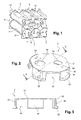
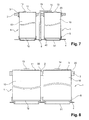
- the figure 6 represents a top view of a holding system mounted with electrochemical accumulators and the Figures 7 and 8 represent sectional views of the maintenance system of the figure 6 respectively according to AA and BB.
- Each electrochemical accumulator 1 has a container 10 comprising a cover 11 provided with terminals 13, 14 of electrical output and a bottom 12 ( Figures 7 and 8 ).
- the terminals 13, 14 of each accumulator 1 are connected to the adjacent battery terminals or to battery power terminals by means of an electrical connection 15.
- the holding system comprises a first flange 2 provided with through openings 20.
- the holding system also comprises a plurality of cups 3. Each cup 3 is adapted to be placed on the lid 3 of an electrochemical accumulator 1. Each cup 3 is also adapted to be received in one of the openings 20 through the first flange 2.
- the holding system is thus modular and mechanically resistant.
- the holding system further comprises a second flange 4.
- the second flange 4 is provided with through openings 40.
- the holding system further comprises a plurality of rings 5.
- Each ring 5 is adapted to be placed on the bottom 12 of an electrochemical accumulator 1.
- Each ring is also adapted to be received in one of the through openings 40 of the second flange 4.
- the entire second flange and the plurality of rings adds modularity and mechanical strength of the holding system.
- Accumulators 1 are intended to be arranged parallel to each other, as shown in FIG. figure 1 .
- the first and second flanges 2, 4 are intended to be arranged parallel to each other, and perpendicular to the longitudinal direction of the accumulators 1.
- the holding system comprises means 6 for clamping the first and second flanges 2, 4, for example tie rods.
- the clamping means 6 allow to bring the first and second flanges 2, 4 from one another by keeping them parallel to each other and then tighten them.
- accumulators 1 can not move, either in the direction of their longitudinal axis (holding by clamping means 6), nor in a transverse direction (holding by the flanges).
- the figure 2 represents a perspective view of a cup of a holding system of electrochemical accumulators.
- the figure 3 represents a sectional view of the cup of the figure 2 according to CC.
- Each cup 3 comprises a substantially cylindrical body 30 closed by a lid 31.
- Each cup 3 may, optionally, include cutouts 37 on its edges 30.
- the cutouts 37 may be formed along the entire height of the edges 30.
- the cuts are for example four in number.
- the lid 31 of each cup 3 has a circle shape amputated by four arcs replaced by segments.
- the segments are substantially parallel two by two.
- two accumulators can be placed closer to each other than if the lid of the cup was in the form of a complete circle. This is visible particularly in figures 1 and 6 .
- the cutouts 37 thus make it possible to increase the compactness of the battery provided with a holding system according to the invention.
- the accumulators do not touch each other at two adjacent cutouts 37. Indeed, the containers 10 accumulators are separated by a portion of the first flange. This part of the first flange between two adjacent accumulators is maximized because of the absence of edges to the cup at this point. This makes it possible to increase the rigidity of the first flange 2.
- the figure 2 also shows two holes 33, 34 on the lid 31 of each cup 3.
- Each of the holes 33, 34 is adapted to allow the passage of one of the terminals 13, 14 of the electrical output of the accumulator 1 on which the cup 3 is intended to be placed.
- the holes 33, 34 may be of different sizes, with a mark 38, 39 of electrical polarity near each of the holes.
- the smaller hole 33 corresponds to the negative terminal and is associated with the marking "-" 38 and the largest hole 34 corresponds to the positive terminal and is associated with the marking "+” 39.
- each cup 3 can not be placed only in a single way on a battery 1, which allows not to be mistaken for subsequent connections to achieve.
- the holes 33, 34 make it possible to ensure that the accumulator 1 is stopped in rotation in the cup 3.
- Each cup 3 may further comprise a lug 36 of keying, located on the body 30.
- This lug 36 is adapted to penetrate into a corresponding groove on the first flange 2. The presence of this lug allows to place in a unique way each cup 3 in a through opening 20 of the first flange. This makes it possible not to make mistakes for subsequent connections to be made.
- the presence of the lug 36 on a cup 3 also makes it possible to stop the cup 3 from rotating relative to the first flange 2.
- the figure 4 is a perspective view of a ring of a holding system of electrochemical accumulators.
- the figure 5 represents a sectional view of the ring of the figure 4 according to DD.
- Each ring 5 comprises a substantially cylindrical body 50.
- the body 50 is preferably closed by a bottom 51.
- each ring 5 serves, once the holding system mounted with accumulators, to protect the battery on which is placed the ring 5.
- the bottom 51 is preferably provided with a separable lid.
- the breakable seal is detached, allowing release of the pressure. Hot gases and / or electrolyte can then escape through the bottom 51 uncapped.
- the funds 51 non-uncapped other rings can protect other accumulators hot gases and / or electrolyte projections. This reduces the risk of contamination of batteries in good condition by electrolyte.
- each cup 3 may comprise shoulders 32 serving as a stop for the first flange 2.
- the shoulders 32 of each cup 3 are located on the body 30 opposite the lid 31.
- each ring 5 may comprise shoulders 52 serving as a stop for the second flange 4.
- the shoulders 52 of each ring 5 are located between the body 50 and the bottom 51.
- the first flange 2 is sandwiched between one end of the clamping means 6 and the shoulders 32 of the plurality of cups 3.
- the second flange 4 is sandwiched between one end clamping means 6 and the shoulders 52 of the plurality of rings 5.
- the shoulders 32, 52 of the cups 3 and rings 5 participate in the good mechanical strength of the holding system once mounted.
- the cups 3 and the rings 5 are for example of electrically insulating material, for example plastic material. Thus, electrical insulation is created by each cup 3 and each ring 5 between the accumulators 1 and the first and second flanges 2, 4.
- the covers 31 of the cups 3 and the bottoms 51 of the rings 5 isolate the accumulators and increase the distances of creepage distances, in particular for the high voltages used for the batteries, for example up to 10 000V.
- the body 30 of the cup 3 may have a height of between 1 mm and the total height of the accumulator.
- the first flange 2 rests against the body 30 of each cup 3. When the cup 3 has cutouts 37, they must have a limited width to prevent the first flange 2 can electrically contact the containers 10 accumulators 1, as this is represented in particular on the figure 8 .
- the second flange 4 rests against the body 50 of the ring 5.
- first and second flanges 2, 4 electrically conductive material for example metal
- metal flanges have the advantage of being inexpensive to manufacture. They also have the advantage of being manufactured by simple machining rather than molding, which is a longer manufacturing process and more restrictive than machining a sheet. The cost and the manufacturing time of the holding system are reduced.
- the machining of the first and second flanges can be achieved for example by cutting by stamping, punching, stamping, laser, water jet, spark erosion, milling or any other technique suitable for machining a sheet.
- the electrical isolation functions of the two terminals and mechanical support are dissociated, which allows the use of electrically conductive material flanges, which have a better mechanical strength than the electrically insulating materials.
- the cups 3 and / or the rings 5 are electrically conductive material.
- the first and / or second flanges 2, 4 are then made of electrically insulating material to ensure electrical insulation between two adjacent accumulators.
- both the cups 3, the rings 5 and the first and second flanges 2, 4 are made of electrically insulating material.
- the first and second flanges 2, 4 are preferably flat. Thus, they are easy to manufacture.
- each cup 3 may comprise at least one boss 35 retaining the first flange 2.
- the bosses 35 of each cup 3 are located on the body, near the lid 31 of the cup 3.
- each ring 5 can comprise at least one boss 55 retaining the second flange 4.
- the bosses 55 of each ring 5 are located on the body, near the bottom 51 of the ring 5.
- This allows a pre-assembly pending fixing by the clamping means 6.
- This also makes it possible to premount the plurality of cups 3 or rings 5 in the plurality of openings 20, 40 through the first flange 2 or the second flange 4 respectively to facilitate the handling of flanges equipped with cups or rings.
- each cup 3 and each ring 5 is slightly elastic, this makes it possible to plug each cup 3 / ring 5 into an opening 20, 40 through the first / second flange 2, 4 by elastic deformation before the cup 3 / ring 5 is placed on the cover 11 / bottom 12 of a battery 1.
- the openings 20, 40 through the first and second flanges 2 have an inner shape corresponding to the outer shape of the cups, respectively the rings, in particular at the edges of the cups, respectively rings.
- each cup 3 serves as a guide element to correctly position the cup 3 on the cover 11 of an accumulator and the cup 3 in a through opening 20 of the first flange.
- the body 50 of each ring 5 serves as a guide element to correctly position the ring 5 on the bottom 12 of an accumulator and the ring 5 in a through opening 40 of the second flange.
- the holding system is modular. Indeed, the same first flange 2 can be used with cups 3 having various hole sizes 33, 34 or positions of holes 33, 34 varied. Similarly, for slightly different accumulator diameters, the same first and second flanges 2, 4 can be used, with cups 3 and rings 5 of the same external shape but of various thicknesses, provided that the thickness is sufficient to provide the electrical insulation described above.
- the holding system also saves development time due to its modularity.
- the invention also relates to a battery comprising a plurality of accumulators and a holding system as described above.
Abstract
Description
La présente invention concerne un système de maintien d'accumulateurs électrochimiques constituant une batterie.The present invention relates to a system for holding electrochemical accumulators constituting a battery.
Une batterie comprend généralement une pluralité d'accumulateurs électrochimiques disposés côte à côte. Chaque accumulateur comprend des bornes de sortie électrique, qui sont reliées aux bornes de sortie électrique d'accumulateurs adjacents. Il est nécessaire de maintenir les accumulateurs afin qu'ils ne puissent pas bouger une fois montés dans la batterie.A battery generally comprises a plurality of electrochemical accumulators arranged side by side. Each accumulator includes electrical output terminals, which are connected to the electrical output terminals of adjacent accumulators. It is necessary to keep the accumulators so that they can not move once mounted in the battery.
Plusieurs solutions de maintien mécanique ont été proposées.Several mechanical maintenance solutions have been proposed.
Il est connu par le document
Il est connu par le document
Il est connu par le document
Dans l'ensemble de ces documents, les flasques sont spécifiques à un unique format d'accumulateur. Par exemple, si le diamètre des accumulateurs varie ou si la position des bornes de sortie des accumulateurs varie, le flasque doit être changé. Ces flasques ne sont donc pas modulaires.In all of these documents, the flanges are specific to a single accumulator format. For example, if the diameter of the accumulators varies or if the position of the output terminals of the accumulators varies, the flange must be changed. These flanges are not modular.
De plus, les flasques doivent présenter une épaisseur limitée au niveau de la zone d'appui sur l'accumulateur afin de ne pas dépasser la hauteur des bornes de sortie électrique des accumulateurs et ainsi ne pas empêcher la connexion entre accumulateurs. Cette limitation de l'épaisseur des flasques nuit à la tenue mécanique du maintien.In addition, the flanges must have a limited thickness in the area of support on the accumulator so as not to exceed the height of the electrical output terminals of the accumulators and thus not to prevent the connection between accumulators. This limitation of the thickness of the flanges adversely affects the mechanical strength of the support.
Il y a donc un besoin pour un système de maintien d'accumulateurs électrochimiques qui soit modulaire et résistant mécaniquement.There is therefore a need for a system for maintaining electrochemical accumulators that is modular and mechanically resistant.
Pour cela, l'invention propose un système de maintien d'accumulateurs électrochimiques, chaque accumulateur présentant un conteneur comprenant un fond et un couvercle muni de bornes de sortie électrique, le système comprenant :
- un premier flasque muni d'ouvertures traversantes ;
- une pluralité de coupelles, chaque coupelle étant adaptée pour être placée sur le couvercle d'un accumulateur électrochimique et pour être reçue dans une des ouvertures traversantes du premier flasque.
- a first flange provided with through openings;
- a plurality of cups, each cup being adapted to be placed on the cover of an electrochemical accumulator and to be received in one of the through openings of the first end plate.
Selon les modes de réalisation, le système de maintien d'accumulateurs électrochimiques selon l'invention peut comprendre une ou plusieurs des caractéristiques suivantes :
- chaque coupelle est en matériau isolant électriquement ;
- chaque premier flasque est en matériau conducteur électriquement ;
- chaque coupelle est en matériau conducteur électriquement ;
- chaque premier flasque est en matériau isolant électriquement ;
- chaque coupelle comprend un épaulement servant de butée au premier flasque ;
- chaque coupelle comprend un moins un bossage de retenue du premier flasque ;
- chaque coupelle comprend des découpes sur ses bords ;
- chaque coupelle comprend deux trous de tailles différentes et un marquage de polarité électrique, chacun des trous permettant le passage d'une des bornes de sortie électrique d'un accumulateur ;
- chaque coupelle comprend en outre un ergot de détrompage ;
- each cup is made of electrically insulating material;
- each first flange is electrically conductive material;
- each cup is electrically conductive material;
- each first flange is of electrically insulating material;
- each cup comprises a shoulder serving as an abutment to the first flange;
- each cup comprises at least one retaining boss of the first flange;
- each cup has cutouts on its edges;
- each cup comprises two holes of different sizes and an electrical polarity marking, each of the holes allowing the passage of one of the electrical output terminals of an accumulator;
- each cup further comprises a fool pin;
Le système de maintien d'accumulateurs électrochimiques selon l'invention peut comprendre en outre :
- un deuxième flasque muni d'ouvertures traversantes ;
- une pluralité de bagues, chaque bague étant adaptée à être placée sur le fond d'un accumulateur électrochimique et à être reçue dans une des ouvertures traversantes du deuxième flasque.
- a second flange provided with through openings;
- a plurality of rings, each ring being adapted to be placed on the bottom of an electrochemical accumulator and to be received in one of the through openings of the second flange.
Selon les modes de réalisation, le système de maintien d'accumulateurs électrochimiques selon l'invention peut comprendre une ou plusieurs des caractéristiques suivantes :
- chaque bague est en matériau isolant électriquement ;
- chaque deuxième flasque est en matériau conducteur électriquement ;
- chaque bague est en matériau conducteur électriquement ;
- chaque deuxième flasque est en matériau isolant électriquement ;
- chaque bague est munie d'un fond comprenant un opercule sécable ;
- chaque bague comprend un épaulement servant de butée au deuxième flasque ;
- chaque bague comprend un moins un bossage de retenue du deuxième flasque ;
- each ring is of electrically insulating material;
- each second flange is electrically conductive material;
- each ring is electrically conductive material;
- each second flange is of electrically insulating material;
- each ring is provided with a bottom comprising a breakable lid;
- each ring comprises a shoulder serving as an abutment to the second flange;
- each ring comprises at least one retaining boss of the second flange;
L'invention concerne aussi une batterie comprenant une pluralité d'accumulateurs électrochimiques et un système de maintien selon l'invention.The invention also relates to a battery comprising a plurality of electrochemical accumulators and a holding system according to the invention.
D'autres caractéristiques et avantages de l'invention apparaîtront à la lecture de la description détaillée qui suit des modes de réalisation de l'invention donnés à titre d'exemple uniquement et en référence aux dessins qui montrent :
-
figure 1 , une vue en perspective d'un système de maintien monté avec des accumulateurs électrochimiques ; -
figure 2 , une vue en perspective d'une coupelle d'un système de maintien d'accumulateurs électrochimiques ; -
figure 3 , une vue en coupe de la coupelle de lafigure 2 selon C-C ; -
figure 4 , une vue en perspective d'une bague d'un système de maintien d'accumulateurs électrochimiques ; -
figure 5 , une vue en coupe de la bague de lafigure 4 selon D-D ; -
figure 6 , une vue de dessus d'un système de maintien monté avec des accumulateurs électrochimiques ; -
figure 7 , une vue en coupe du système de maintien de lafigure 6 selon A-A ; -
figure 8 , une vue en coupe du système de maintien de lafigure 6 selon B-B.
-
figure 1 , a perspective view of a holding system mounted with electrochemical accumulators; -
figure 2 , a perspective view of a cup of a holding system of electrochemical accumulators; -
figure 3 , a sectional view of the cup of thefigure 2 according to CC; -
figure 4 , a perspective view of a ring of a holding system for electrochemical accumulators; -
figure 5 , a sectional view of the ring of thefigure 4 according to DD; -
figure 6 a top view of a holding system mounted with electrochemical accumulators; -
figure 7 , a sectional view of the maintenance system of thefigure 6 according to AA; -
figure 8 , a sectional view of the maintenance system of thefigure 6 according to BB.
Les numéros de référence qui sont identiques sur les différentes figures représentent des éléments identiques ou similaires.The reference numbers which are identical in the different figures represent identical or similar elements.
L'invention concerne un système de maintien d'accumulateurs électrochimiques, chaque accumulateur présentant un conteneur présentant un fond et un couvercle muni de bornes de sortie électrique. Le système de maintien comprend un premier flasque muni d'ouvertures traversantes et une pluralité de coupelles. Chaque coupelle est adaptée pour être placée sur le couvercle d'un accumulateur électrochimique et pour être reçue dans une des ouvertures traversantes du premier flasque.The invention relates to a system for holding electrochemical accumulators, each accumulator having a container having a bottom and a lid provided with electrical output terminals. The holding system comprises a first flange provided with through openings and a plurality of cups. Each cup is adapted to be placed on the cover of an electrochemical accumulator and to be received in one of the through openings of the first end plate.
Le système de maintien selon l'invention est modulaire. En effet, les coupelles sont adaptées aux accumulateurs qu'elles doivent recevoir. En revanche, le même premier flasque peut être utilisé avec différentes coupelles. Ainsi, si le diamètre des accumulateurs varie ou si la position des bornes de sortie des accumulateurs varie, seules les coupelles doivent être changées mais pas le flasque. De même, si une coupelle est abîmée, seule la coupelle est à changer et non tout le flasque.The holding system according to the invention is modular. Indeed, the cups are adapted to the accumulators they must receive. On the other hand, the same first flange can be used with different cups. Thus, if the diameter of the accumulators varies or if the position of the output terminals of the accumulators varies, only the cups must be changed but not the flask. Similarly, if a cup is damaged, only the cup is to change and not all the flange.
De plus, la zone de maintien mécanique des accumulateurs est déplacée sur le corps du conteneur et libère l'accès aux bornes de sortie électrique. Ainsi, l'épaisseur du flasque peut être aussi important que nécessaire pour assurer une bonne tenue mécanique du système de maintien une fois monté. Le système de maintien selon l'invention est donc plus résistant mécaniquement que les systèmes connus de l'art antérieur.In addition, the mechanical holding area of the accumulators is moved on the body of the container and releases access to the electrical output terminals. Thus, the thickness of the flange may be as large as necessary to ensure good mechanical strength of the holding system once mounted. The holding system according to the invention is therefore more mechanically resistant than the known systems of the prior art.
Le système de maintien comprend en outre un deuxième flasque muni d'ouvertures traversantes et une pluralité de bagues. Chaque bague est adaptée pour être placée sur le fond d'un accumulateur électrochimique et pour être reçue dans une des ouvertures traversantes du deuxième flasque.The holding system further comprises a second flange provided with through openings and a plurality of rings. Each ring is adapted to be placed on the bottom of an electrochemical accumulator and to be received in one of the through openings of the second flange.
Le système de maintien selon l'invention est encore modulaire avec le deuxième flasque et les bagues. En effet, les bagues sont adaptées aux accumulateurs qu'elles doivent recevoir. En revanche, le même deuxième flasque peut être utilisé avec différentes bagues. Ainsi, si le diamètre des accumulateurs varie, seules les bagues doivent être changées mais pas le flasque. De même, si une bague est abîmée, seule la bague est à changer et non tout le flasque.The holding system according to the invention is still modular with the second flange and the rings. Indeed, the rings are adapted to the accumulators they must receive. On the other hand, the same second flange can be used with different rings. Thus, if the diameter of the accumulators varies, only the rings must be changed but not the flange. Similarly, if a ring is damaged, only the ring is to change and not all the flange.
La
Chaque accumulateur 1 électrochimique présente un conteneur 10 comprenant un couvercle 11 muni de bornes 13, 14 de sortie électrique et un fond 12 (
Le système de maintien comprend un premier flasque 2 muni d'ouvertures 20 traversantes.The holding system comprises a
Le système de maintien comprend également une pluralité de coupelles 3. Chaque coupelle 3 est adaptée à être placée sur le couvercle 3 d'un accumulateur 1 électrochimique. Chaque coupelle 3 est également adaptée à être reçue dans une des ouvertures 20 traversantes du premier flasque 2.The holding system also comprises a plurality of
Comme expliqué plus haut, le système de maintien est ainsi modulaire et résistant mécaniquement.As explained above, the holding system is thus modular and mechanically resistant.
Le système de maintien comprend en outre un deuxième flasque 4. Le deuxième flasque 4 est muni d'ouvertures 40 traversantes.The holding system further comprises a
Le système de maintien comprend en outre une pluralité de bagues 5. Chaque bague 5 est adaptée à être placée sur le fond 12 d'un accumulateur 1 électrochimique. Chaque bague est également adaptée à être reçue dans une des ouvertures 40 traversantes du deuxième flasque 4.The holding system further comprises a plurality of
L'ensemble du deuxième flasque et de la pluralité de bagues ajoute en modularité et en tenue mécanique du système de maintien.The entire second flange and the plurality of rings adds modularity and mechanical strength of the holding system.
Les accumulateurs 1 sont destinés à être disposés parallèlement les uns aux autres, comme représenté sur la
Le système de maintien comprend des moyens 6 de serrage des premier et deuxième flasques 2, 4, par exemple des tirants. Les moyens 6 de serrage permettent de rapprocher les premier et deuxième flasques 2, 4 l'un de l'autre en les maintenant parallèles l'un à l'autre puis de les serrer. Ainsi, une fois le système de maintien monté, les accumulateurs 1 ne peuvent plus bouger, ni selon la direction de leur axe longitudinal (maintien par moyen 6 de serrage), ni selon une direction transversale (maintien par les flasques).The holding system comprises means 6 for clamping the first and
La
Chaque coupelle 3 comprend un corps 30 sensiblement cylindrique fermé par un couvercle 31.Each
Chaque coupelle 3 peut, de façon optionnelle, comprendre des découpes 37 sur ses bords 30. Les découpes 37 peuvent être ménagées sur toute la hauteur des bords 30. Les découpes sont par exemple au nombre de quatre. Ainsi, le couvercle 31 de chaque coupelle 3 a une forme de cercle amputé de quatre arcs de cercle remplacés par des segments. Les segments sont sensiblement parallèles deux à deux. Ainsi, deux accumulateurs peuvent être placés plus près l'un de l'autre que si le couvercle de la coupelle était en forme de cercle complet. Cela est visible en particulier sur les
Comme représenté sur la
Une fois le système de maintien monté avec des accumulateurs, la présence des découpes 37 sur une coupelle 3 permet d'assurer l'arrêt en rotation de la coupelle 3 par rapport au flasque 2.Once the holding system mounted with accumulators, the presence of the
Par ailleurs, la
Les trous 33, 34 peuvent être de tailles différentes, avec un marquage 38, 39 de polarité électrique à proximité de chacun des trous. Sur la
Chaque coupelle 3 peut en outre comprendre un ergot 36 de détrompage, situé sur le corps 30. Cet ergot 36 est adapté à pénétrer dans une rainure correspondante sur le premier flasque 2. La présence de cet ergot permet de placer d'une unique façon chaque coupelle 3 dans une ouverture 20 traversante du premier flasque. Cela permet de ne pas se tromper pour les connexions ultérieures à réaliser.Each
Une fois le système de maintien monté, la présence de l'ergot 36 sur une coupelle 3 permet également d'assurer l'arrêt en rotation de la coupelle 3 par rapport au premier flasque 2.Once the holding system has been mounted, the presence of the
La
Chaque bague 5 comprend un corps 50 sensiblement cylindrique. Le corps 50 est de préférence fermé par un fond 51.Each
Le fond 51 de chaque bague 5 sert, une fois le système de maintien monté avec des accumulateurs, à protéger l'accumulateur sur lequel est placée la bague 5. Le fond 51 est de préférence muni d'un opercule sécable. Ainsi, dans le cas où un accumulateur monté dans une batterie en fonctionnement est soumis à de fortes pressions et présente un dispositif de sécurité pour évacuer la surpression par le fond, l'opercule sécable se détache, permettant de libérer la pression. Des gaz chauds et/ou de l'électrolyte peuvent alors s'échapper par le fond 51 désoperculé. Les fonds 51 non désoperculés des autres bagues permettent de protéger les autres accumulateurs des gaz chauds et/ou des projections d'électrolyte. Cela diminue le risque de contamination des accumulateurs en bon état par de l'électrolyte.The bottom 51 of each
Ainsi, après montage du système de maintien avec des accumulateurs, un espace existe entre le fond 12 de l'accumulateur et le fond 51 de la bague 5. Cet espace peut recevoir le gaz libéré par l'accumulateur lorsque le dispositif de sécurité est activé. Si la pression reste limitée, l'opercule de la bague ne se déchirera pas. Le gaz et l'électrolyte ne se répandront pas.Thus, after mounting the holding system with accumulators, a space exists between the bottom 12 of the accumulator and the bottom 51 of the
Par ailleurs, chaque coupelle 3 peut comprendre des épaulements 32 servant de butée au premier flasque 2. Les épaulements 32 de chaque coupelle 3 sont situés sur le corps 30 à l'opposé du couvercle 31.Furthermore, each
De même, chaque bague 5 peut comprendre des épaulements 52 servant de butée au deuxième flasque 4. Les épaulements 52 de chaque bague 5 sont situés entre le corps 50 et le fond 51.Similarly, each
Ainsi, après montage du système de maintien, le premier flasque 2 est pris en sandwich entre une extrémité des moyens 6 de serrage et les épaulements 32 de la pluralité de coupelles 3. De même, le deuxième flasque 4 est pris en sandwich entre une extrémité des moyens 6 de serrage et les épaulements 52 de la pluralité de bagues 5. Les épaulements 32, 52 des coupelles 3 et des bagues 5 participent à la bonne tenue mécanique du système de maintien une fois monté.Thus, after mounting the holding system, the
Les coupelles 3 et les bagues 5 sont par exemple en matériau isolant électriquement, par exemple en matériau plastique. Ainsi, une isolation électrique est créée par chaque coupelle 3 et chaque bague 5 entre les accumulateurs 1 et les premier et deuxième flasques 2, 4.The
En particulier, les couvercles 31 des coupelles 3 et les fonds 51 des bagues 5 isolent les accumulateurs et augmentent les distances de lignes de fuite, en particulier pour les hautes tensions utilisées pour les batteries, par exemple jusqu'à 10 000V.In particular, the
Le corps 30 de la coupelle 3 peut présenter une hauteur comprise entre 1 mm et la hauteur totale de l'accumulateur.The
Le premier flasque 2 repose contre le corps 30 de chaque coupelle 3. Lorsque la coupelle 3 comporte des découpes 37, celles-ci doivent présenter une largeur limitée pour éviter que le premier flasque 2 puisse contacter électriquement les conteneurs 10 des accumulateurs 1, comme cela est représenté en particulier sur la
Le deuxième flasque 4 repose contre le corps 50 de la bague 5.The
Il est donc possible de réaliser les premier et deuxième flasques 2, 4 en matériau conducteur électriquement, par exemple en métal, puisqu'ils sont isolés des accumulateurs. Des flasques métalliques présentent l'avantage d'être peu coûteux à fabriquer. Ils présentent également l'avantage de pouvoir être fabriqués par simple usinage plutôt que par moulage, qui est un procédé de fabrication plus long et plus contraignant que l'usinage d'une tôle. Le coût et le temps de fabrication du système de maintien sont donc réduits. L'usinage des premier et deuxième flasques peut être réalisé par exemple par découpe par emboutissage, poinçonnage, matriçage, laser, jet d'eau, électroérosion, fraisage ou toute autre technique appropriée à l'usinage d'une tôle.It is therefore possible to make the first and
De plus, les fonctions d'isolation électrique des deux bornes et de maintien mécanique sont dissociées, ce qui permet d'utiliser des flasques en matériau conducteur électriquement, qui présenterait une meilleure tenue mécanique que les matériaux isolant électriquement.In addition, the electrical isolation functions of the two terminals and mechanical support are dissociated, which allows the use of electrically conductive material flanges, which have a better mechanical strength than the electrically insulating materials.
En variante, les coupelles 3 et/ou les bagues 5 sont en matériau conducteur électriquement. Les premier et/ou deuxième flasques 2, 4 sont alors en matériau isolant électriquement afin de garantir l'isolation électrique entre deux accumulateurs adjacents.Alternatively, the
Dans une autre variante, à la fois les coupelles 3, les bagues 5 et les premier et deuxième flasques 2, 4 sont en matériau isolant électriquement.In another variant, both the
Les premier et deuxième flasques 2, 4 sont de préférence plans. Ainsi, ils sont faciles à fabriquer.The first and
Des flasques plans et peu épais autorisent une déformation des flasques. Cela permet de maintenir le système de maintien monté sous charge afin d'améliorer la tenue aux vibrations sans que le fléchissement issu de la déformation induite par la charge n'interfère avec les connexions 15.Flat and thin flanges allow deformation of the flanges. This makes it possible to maintain the support system mounted under load in order to improve the vibration resistance without the bending resulting from the deformation induced by the load interfering with the
En outre, chaque coupelle 3 peut comprendre au moins un bossage 35 de retenue du premier flasque 2. Les bossages 35 de chaque coupelle 3 sont situés sur le corps, à proximité du couvercle 31 de la coupelle 3. De même, chaque bague 5 peut comprendre au moins un bossage 55 de retenue du deuxième flasque 4. Les bossages 55 de chaque bague 5 sont situés sur le corps, à proximité du fond 51 de la bague 5.In addition, each
Ainsi, lorsque chaque coupelle 3 est reçue dans une ouverture 20 traversante du premier flasque 2, le premier flasque 2 est maintenu en position entre les épaulements 32 de la coupelle 3 et les bossages 35 de la coupelle. De même, lorsque chaque bague 5 est reçue dans une ouverture 40 traversante du deuxième flasque 4, le deuxième flasque 4 est maintenu en position entre les épaulements 52 de la bague 5 et les bossages 55 de la bague 5.Thus, when each
Cela permet un pré-montage en attendant la fixation par les moyens 6 de serrage. Cela permet également de prémonter la pluralité de coupelles 3 ou de bagues 5 dans la pluralité d'ouvertures 20, 40 traversantes du premier flasque 2 ou du deuxième flasque 4 respectivement afin de faciliter la manutention de flasques équipées de coupelles ou de bagues.This allows a pre-assembly pending fixing by the clamping means 6. This also makes it possible to premount the plurality of
Dans le cas où le matériau de chaque coupelle 3 et de chaque bague 5 est légèrement élastique, cela permet d'enficher chaque coupelle 3/bague 5 dans une ouverture 20, 40 traversante du premier/deuxième flasque 2, 4 par déformation élastique avant que la coupelle 3/bague 5 soit placée sur le couvercle 11/fond 12 d'un accumulateur 1.In the case where the material of each
Les ouvertures 20, 40 traversantes des premier et deuxième flasques 2 ont une forme intérieure correspondant à la forme extérieure des coupelles, respectivement des bagues, en particulier au niveau des bords des coupelles, respectivement des bagues.The
Le corps 30 de chaque coupelle 3 sert d'élément de guidage pour positionner correctement la coupelle 3 sur le couvercle 11 d'un accumulateur puis la coupelle 3 dans une ouverture 20 traversante du premier flasque. De même, le corps 50 de chaque bague 5 sert d'élément de guidage pour positionner correctement la bague 5 sur le fond 12 d'un accumulateur puis la bague 5 dans une ouverture 40 traversante du deuxième flasque.The
Le système de maintien est modulaire. En effet, le même premier flasque 2 peut être utilisé avec des coupelles 3 ayant des tailles de trous 33, 34 variées ou des positionnements de trous 33, 34 variés. De même, pour des diamètres d'accumulateurs légèrement différents, les mêmes premier et deuxième flasques 2, 4 peuvent être utilisés, avec des coupelles 3 et des bagues 5 de même forme extérieure mais d'épaisseurs variées, à la condition que l'épaisseur soit suffisante pour assurer l'isolation électrique décrite plus haut.The holding system is modular. Indeed, the same
Le système de maintien peut donc assurer une multitude de fonctions en plus de la fixation mécanique des accumulateurs :
- l'isolation électrique des accumulateurs,
- le détrompage des accumulateurs, assuré par les trous 33, 34 de tailles différentes des coupelles 3, avec le marquage 38, 39 associé, ainsi que
par l'ergot 36 de chaque coupelle 3, - le pré-montage des accumulateurs, assuré par les bossages 35 et les épaulements 32 de chaque coupelle 3 et les bossages 55 et les épaulements 52 de chaque bague 5,
- la protection et l'étanchéité des accumulateurs aux projections de gaz chaud et/ou d'électrolyte, assurée par le fond 51 de chaque bague 5.
- electrical insulation of accumulators,
- the keying of the accumulators, ensured by the
holes cups 3, with the marking 38, 39 associated, as well as by thelug 36 of eachcup 3, - the pre-assembly of the accumulators, ensured by the
bosses 35 and theshoulders 32 of eachcup 3 and thebosses 55 and theshoulders 52 of eachring 5, - the protection and the sealing of the accumulators with projections of hot gas and / or electrolyte, ensured by the bottom 51 of each
ring 5.
Le système de maintien permet également de gagner en temps de développement du fait de sa modularité.The holding system also saves development time due to its modularity.
L'invention concerne également une batterie comprenant une pluralité d'accumulateurs et un système de maintien tel que décrit ci-dessus.The invention also relates to a battery comprising a plurality of accumulators and a holding system as described above.
Claims (19)
Applications Claiming Priority (1)
| Application Number | Priority Date | Filing Date | Title |
|---|---|---|---|
| FR0807051A FR2939969B1 (en) | 2008-12-16 | 2008-12-16 | SYSTEM FOR MAINTAINING ELECTROCHEMICAL BATTERIES |
Publications (2)
| Publication Number | Publication Date |
|---|---|
| EP2200110A1 true EP2200110A1 (en) | 2010-06-23 |
| EP2200110B1 EP2200110B1 (en) | 2014-04-16 |
Family
ID=40845718
Family Applications (1)
| Application Number | Title | Priority Date | Filing Date |
|---|---|---|---|
| EP09178761.4A Active EP2200110B1 (en) | 2008-12-16 | 2009-12-10 | System for maintaining electrochemical accumulators |
Country Status (4)
| Country | Link |
|---|---|
| US (1) | US8329332B2 (en) |
| EP (1) | EP2200110B1 (en) |
| ES (1) | ES2478818T3 (en) |
| FR (1) | FR2939969B1 (en) |
Cited By (5)
| Publication number | Priority date | Publication date | Assignee | Title |
|---|---|---|---|---|
| WO2014118199A1 (en) * | 2013-02-04 | 2014-08-07 | Robert Bosch Gmbh | Battery cell and module housing comprising positioning apparatus, and corresponding battery module comprising battery cell and module housing |
| WO2017178634A1 (en) | 2016-04-14 | 2017-10-19 | Saft | Assembly of electrochemical elements using an additive manufacturing method |
| EP2403050B1 (en) * | 2010-07-02 | 2018-07-18 | Saft | Battery of electrochemical generators including a foam as a filling material between generators |
| WO2019145652A1 (en) * | 2018-01-29 | 2019-08-01 | Commissariat A L'energie Atomique Et Aux Energies Alternatives | Electric storage cell module and battery comprising a plurality of modules |
| WO2019145653A1 (en) * | 2018-01-29 | 2019-08-01 | Commissariat A L'energie Atomique Et Aux Energies Alternatives | Electric storage cell module, and battery comprising a plurality of modules |
Families Citing this family (3)
| Publication number | Priority date | Publication date | Assignee | Title |
|---|---|---|---|---|
| WO2017034543A1 (en) | 2015-08-24 | 2017-03-02 | Elitise Llc | Battery module housing assembly |
| US10347888B2 (en) * | 2016-09-07 | 2019-07-09 | Thunder Power New Energy Vehicle Development Company Limited | Battery system housing with underside armor |
| DE202017103801U1 (en) * | 2017-06-26 | 2018-10-01 | SOLO Vertriebs- und Entwicklungs-GmbH | Retaining element for a battery cell assembly |
Citations (3)
| Publication number | Priority date | Publication date | Assignee | Title |
|---|---|---|---|---|
| EP1109237A1 (en) * | 1999-12-13 | 2001-06-20 | Alcatel | Module configuration |
| WO2008074034A1 (en) * | 2006-12-14 | 2008-06-19 | Johnson Controls - Saft Advanced Power Solutions Llc | Battery module |
| EP1953848A1 (en) | 2007-02-02 | 2008-08-06 | Samsung SDI Co., Ltd. | Welding-Type Fixing Cap and Cell Module Equipped with same |
Family Cites Families (1)
| Publication number | Priority date | Publication date | Assignee | Title |
|---|---|---|---|---|
| US20090155680A1 (en) * | 2005-03-16 | 2009-06-18 | Ford Global Technologies, Llc | Power supply system |
-
2008
- 2008-12-16 FR FR0807051A patent/FR2939969B1/en not_active Expired - Fee Related
-
2009
- 2009-12-10 EP EP09178761.4A patent/EP2200110B1/en active Active
- 2009-12-10 ES ES09178761.4T patent/ES2478818T3/en active Active
- 2009-12-15 US US12/638,282 patent/US8329332B2/en active Active
Patent Citations (3)
| Publication number | Priority date | Publication date | Assignee | Title |
|---|---|---|---|---|
| EP1109237A1 (en) * | 1999-12-13 | 2001-06-20 | Alcatel | Module configuration |
| WO2008074034A1 (en) * | 2006-12-14 | 2008-06-19 | Johnson Controls - Saft Advanced Power Solutions Llc | Battery module |
| EP1953848A1 (en) | 2007-02-02 | 2008-08-06 | Samsung SDI Co., Ltd. | Welding-Type Fixing Cap and Cell Module Equipped with same |
Cited By (8)
| Publication number | Priority date | Publication date | Assignee | Title |
|---|---|---|---|---|
| EP2403050B1 (en) * | 2010-07-02 | 2018-07-18 | Saft | Battery of electrochemical generators including a foam as a filling material between generators |
| WO2014118199A1 (en) * | 2013-02-04 | 2014-08-07 | Robert Bosch Gmbh | Battery cell and module housing comprising positioning apparatus, and corresponding battery module comprising battery cell and module housing |
| WO2017178634A1 (en) | 2016-04-14 | 2017-10-19 | Saft | Assembly of electrochemical elements using an additive manufacturing method |
| WO2019145652A1 (en) * | 2018-01-29 | 2019-08-01 | Commissariat A L'energie Atomique Et Aux Energies Alternatives | Electric storage cell module and battery comprising a plurality of modules |
| WO2019145653A1 (en) * | 2018-01-29 | 2019-08-01 | Commissariat A L'energie Atomique Et Aux Energies Alternatives | Electric storage cell module, and battery comprising a plurality of modules |
| FR3077430A1 (en) * | 2018-01-29 | 2019-08-02 | Commissariat A L'energie Atomique Et Aux Energies Alternatives | ELECTRICAL BATTERY AND BATTERY MODULE COMPRISING MULTIPLE MODULES |
| FR3077431A1 (en) * | 2018-01-29 | 2019-08-02 | Commissariat A L'energie Atomique Et Aux Energies Alternatives | ELECTRICAL BATTERY AND BATTERY MODULE COMPRISING MULTIPLE MODULES |
| CN111656561A (en) * | 2018-01-29 | 2020-09-11 | 原子能与替代能源委员会 | Electricity storage battery module and battery comprising a plurality of modules |
Also Published As
| Publication number | Publication date |
|---|---|
| FR2939969B1 (en) | 2010-12-10 |
| FR2939969A1 (en) | 2010-06-18 |
| EP2200110B1 (en) | 2014-04-16 |
| US20100151314A1 (en) | 2010-06-17 |
| US8329332B2 (en) | 2012-12-11 |
| ES2478818T3 (en) | 2014-07-23 |
Similar Documents
| Publication | Publication Date | Title |
|---|---|---|
| EP2200110B1 (en) | System for maintaining electrochemical accumulators | |
| EP2034539B1 (en) | Battery made up of a plurality of cells positioned and connected to one another without welding | |
| EP2809537B1 (en) | Housing for an electric module of a battery pack for a motor vehicle and corresponding battery pack | |
| EP2093820B1 (en) | Electric connection for current accumulator | |
| EP2845245A1 (en) | Device for supporting a power storage assembly | |
| EP0913874A1 (en) | Sealed storage battery with multilayered jacket | |
| FR2737940A1 (en) | BATTERY OF HIGH TEMPERATURE ELECTRIC ACCUMULATORS | |
| EP1221728B1 (en) | A resealable valve and electrochemical generator comprising said valve | |
| EP0209717B1 (en) | Battery compartment for an electronic watch | |
| EP3410514B1 (en) | Bushing forming a terminal for a metal-ion storage cell, including a gas release valve, associated cell | |
| EP3180790A1 (en) | Basket for transport and/or storage of radioactive materials | |
| EP2828906B1 (en) | Energy storage assembly comprising an electrically insulating elastic ring | |
| EP2751820A1 (en) | Connector arranged between two cylindrical energy storage assemblies | |
| EP4002572A1 (en) | Metal-ion accumulator provided with a degassing conduit, associated battery module or battery pack with liquid cooling | |
| WO2012168648A1 (en) | Device for cooling cylindrical electrochemical cells | |
| FR2695758A1 (en) | Electrochemical accumulator element, battery of accumulator elements and method for manufacturing this accumulator element. | |
| FR3073671A1 (en) | ENERGY BLOCK CONSISTING OF SOLDER-FREE ASSEMBLY OF A PLURALITY OF BATTERY CELLS | |
| FR2780555A1 (en) | HOLDING DEVICE FOR MONOBLOCK BATTERY | |
| FR2908740A1 (en) | Cylindrical container for e.g. lithium-ion battery, has wall with periphery part by which container rests on plane surface, and thin zone arranged on central part of wall, where thin zone is encased by over-pressure inside container | |
| EP3549186B1 (en) | Alkaline battery | |
| WO2023117952A1 (en) | Battery cell and associated manufacturing method | |
| EP3576177B1 (en) | Encapsulated microbattery having improved sealing and encapsulation process providing improved sealing | |
| EP4342018A1 (en) | Electrochemical element for a battery, and corresponding battery | |
| WO2024008641A1 (en) | Assembly and corresponding manufacturing method | |
| FR3125633A1 (en) | Electrochemical cell for electrical energy storage |
Legal Events
| Date | Code | Title | Description |
|---|---|---|---|
| PUAI | Public reference made under article 153(3) epc to a published international application that has entered the european phase |
Free format text: ORIGINAL CODE: 0009012 |
|
| AK | Designated contracting states |
Kind code of ref document: A1 Designated state(s): AT BE BG CH CY CZ DE DK EE ES FI FR GB GR HR HU IE IS IT LI LT LU LV MC MK MT NL NO PL PT RO SE SI SK SM TR |
|
| AX | Request for extension of the european patent |
Extension state: AL BA RS |
|
| 17P | Request for examination filed |
Effective date: 20101223 |
|
| 17Q | First examination report despatched |
Effective date: 20110922 |
|
| GRAP | Despatch of communication of intention to grant a patent |
Free format text: ORIGINAL CODE: EPIDOSNIGR1 |
|
| INTG | Intention to grant announced |
Effective date: 20131126 |
|
| GRAS | Grant fee paid |
Free format text: ORIGINAL CODE: EPIDOSNIGR3 |
|
| GRAA | (expected) grant |
Free format text: ORIGINAL CODE: 0009210 |
|
| AK | Designated contracting states |
Kind code of ref document: B1 Designated state(s): AT BE BG CH CY CZ DE DK EE ES FI FR GB GR HR HU IE IS IT LI LT LU LV MC MK MT NL NO PL PT RO SE SI SK SM TR |
|
| REG | Reference to a national code |
Ref country code: GB Ref legal event code: FG4D Free format text: NOT ENGLISH |
|
| REG | Reference to a national code |
Ref country code: CH Ref legal event code: EP |
|
| REG | Reference to a national code |
Ref country code: AT Ref legal event code: REF Ref document number: 663010 Country of ref document: AT Kind code of ref document: T Effective date: 20140515 |
|
| REG | Reference to a national code |
Ref country code: IE Ref legal event code: FG4D Free format text: LANGUAGE OF EP DOCUMENT: FRENCH |
|
| REG | Reference to a national code |
Ref country code: DE Ref legal event code: R096 Ref document number: 602009023249 Country of ref document: DE Effective date: 20140528 |
|
| REG | Reference to a national code |
Ref country code: ES Ref legal event code: FG2A Ref document number: 2478818 Country of ref document: ES Kind code of ref document: T3 Effective date: 20140723 |
|
| REG | Reference to a national code |
Ref country code: AT Ref legal event code: MK05 Ref document number: 663010 Country of ref document: AT Kind code of ref document: T Effective date: 20140416 |
|
| REG | Reference to a national code |
Ref country code: NL Ref legal event code: VDEP Effective date: 20140416 |
|
| REG | Reference to a national code |
Ref country code: LT Ref legal event code: MG4D |
|
| PG25 | Lapsed in a contracting state [announced via postgrant information from national office to epo] |
Ref country code: GR Free format text: LAPSE BECAUSE OF FAILURE TO SUBMIT A TRANSLATION OF THE DESCRIPTION OR TO PAY THE FEE WITHIN THE PRESCRIBED TIME-LIMIT Effective date: 20140717 Ref country code: LT Free format text: LAPSE BECAUSE OF FAILURE TO SUBMIT A TRANSLATION OF THE DESCRIPTION OR TO PAY THE FEE WITHIN THE PRESCRIBED TIME-LIMIT Effective date: 20140416 Ref country code: NO Free format text: LAPSE BECAUSE OF FAILURE TO SUBMIT A TRANSLATION OF THE DESCRIPTION OR TO PAY THE FEE WITHIN THE PRESCRIBED TIME-LIMIT Effective date: 20140716 Ref country code: NL Free format text: LAPSE BECAUSE OF FAILURE TO SUBMIT A TRANSLATION OF THE DESCRIPTION OR TO PAY THE FEE WITHIN THE PRESCRIBED TIME-LIMIT Effective date: 20140416 Ref country code: CY Free format text: LAPSE BECAUSE OF FAILURE TO SUBMIT A TRANSLATION OF THE DESCRIPTION OR TO PAY THE FEE WITHIN THE PRESCRIBED TIME-LIMIT Effective date: 20140416 Ref country code: FI Free format text: LAPSE BECAUSE OF FAILURE TO SUBMIT A TRANSLATION OF THE DESCRIPTION OR TO PAY THE FEE WITHIN THE PRESCRIBED TIME-LIMIT Effective date: 20140416 Ref country code: IS Free format text: LAPSE BECAUSE OF FAILURE TO SUBMIT A TRANSLATION OF THE DESCRIPTION OR TO PAY THE FEE WITHIN THE PRESCRIBED TIME-LIMIT Effective date: 20140816 Ref country code: BG Free format text: LAPSE BECAUSE OF FAILURE TO SUBMIT A TRANSLATION OF THE DESCRIPTION OR TO PAY THE FEE WITHIN THE PRESCRIBED TIME-LIMIT Effective date: 20140716 |
|
| PG25 | Lapsed in a contracting state [announced via postgrant information from national office to epo] |
Ref country code: PL Free format text: LAPSE BECAUSE OF FAILURE TO SUBMIT A TRANSLATION OF THE DESCRIPTION OR TO PAY THE FEE WITHIN THE PRESCRIBED TIME-LIMIT Effective date: 20140416 Ref country code: HR Free format text: LAPSE BECAUSE OF FAILURE TO SUBMIT A TRANSLATION OF THE DESCRIPTION OR TO PAY THE FEE WITHIN THE PRESCRIBED TIME-LIMIT Effective date: 20140416 Ref country code: SE Free format text: LAPSE BECAUSE OF FAILURE TO SUBMIT A TRANSLATION OF THE DESCRIPTION OR TO PAY THE FEE WITHIN THE PRESCRIBED TIME-LIMIT Effective date: 20140416 Ref country code: LV Free format text: LAPSE BECAUSE OF FAILURE TO SUBMIT A TRANSLATION OF THE DESCRIPTION OR TO PAY THE FEE WITHIN THE PRESCRIBED TIME-LIMIT Effective date: 20140416 Ref country code: AT Free format text: LAPSE BECAUSE OF FAILURE TO SUBMIT A TRANSLATION OF THE DESCRIPTION OR TO PAY THE FEE WITHIN THE PRESCRIBED TIME-LIMIT Effective date: 20140416 |
|
| PG25 | Lapsed in a contracting state [announced via postgrant information from national office to epo] |
Ref country code: PT Free format text: LAPSE BECAUSE OF FAILURE TO SUBMIT A TRANSLATION OF THE DESCRIPTION OR TO PAY THE FEE WITHIN THE PRESCRIBED TIME-LIMIT Effective date: 20140818 |
|
| REG | Reference to a national code |
Ref country code: DE Ref legal event code: R097 Ref document number: 602009023249 Country of ref document: DE |
|
| PG25 | Lapsed in a contracting state [announced via postgrant information from national office to epo] |
Ref country code: SK Free format text: LAPSE BECAUSE OF FAILURE TO SUBMIT A TRANSLATION OF THE DESCRIPTION OR TO PAY THE FEE WITHIN THE PRESCRIBED TIME-LIMIT Effective date: 20140416 Ref country code: CZ Free format text: LAPSE BECAUSE OF FAILURE TO SUBMIT A TRANSLATION OF THE DESCRIPTION OR TO PAY THE FEE WITHIN THE PRESCRIBED TIME-LIMIT Effective date: 20140416 Ref country code: DK Free format text: LAPSE BECAUSE OF FAILURE TO SUBMIT A TRANSLATION OF THE DESCRIPTION OR TO PAY THE FEE WITHIN THE PRESCRIBED TIME-LIMIT Effective date: 20140416 Ref country code: EE Free format text: LAPSE BECAUSE OF FAILURE TO SUBMIT A TRANSLATION OF THE DESCRIPTION OR TO PAY THE FEE WITHIN THE PRESCRIBED TIME-LIMIT Effective date: 20140416 Ref country code: RO Free format text: LAPSE BECAUSE OF FAILURE TO SUBMIT A TRANSLATION OF THE DESCRIPTION OR TO PAY THE FEE WITHIN THE PRESCRIBED TIME-LIMIT Effective date: 20140416 |
|
| PLBE | No opposition filed within time limit |
Free format text: ORIGINAL CODE: 0009261 |
|
| STAA | Information on the status of an ep patent application or granted ep patent |
Free format text: STATUS: NO OPPOSITION FILED WITHIN TIME LIMIT |
|
| 26N | No opposition filed |
Effective date: 20150119 |
|
| REG | Reference to a national code |
Ref country code: DE Ref legal event code: R097 Ref document number: 602009023249 Country of ref document: DE Effective date: 20150119 |
|
| PG25 | Lapsed in a contracting state [announced via postgrant information from national office to epo] |
Ref country code: BE Free format text: LAPSE BECAUSE OF NON-PAYMENT OF DUE FEES Effective date: 20141231 |
|
| PG25 | Lapsed in a contracting state [announced via postgrant information from national office to epo] |
Ref country code: LU Free format text: LAPSE BECAUSE OF FAILURE TO SUBMIT A TRANSLATION OF THE DESCRIPTION OR TO PAY THE FEE WITHIN THE PRESCRIBED TIME-LIMIT Effective date: 20141210 Ref country code: SI Free format text: LAPSE BECAUSE OF FAILURE TO SUBMIT A TRANSLATION OF THE DESCRIPTION OR TO PAY THE FEE WITHIN THE PRESCRIBED TIME-LIMIT Effective date: 20140416 |
|
| REG | Reference to a national code |
Ref country code: CH Ref legal event code: PL |
|
| REG | Reference to a national code |
Ref country code: IE Ref legal event code: MM4A |
|
| PG25 | Lapsed in a contracting state [announced via postgrant information from national office to epo] |
Ref country code: IE Free format text: LAPSE BECAUSE OF NON-PAYMENT OF DUE FEES Effective date: 20141210 Ref country code: CH Free format text: LAPSE BECAUSE OF NON-PAYMENT OF DUE FEES Effective date: 20141231 Ref country code: LI Free format text: LAPSE BECAUSE OF NON-PAYMENT OF DUE FEES Effective date: 20141231 |
|
| REG | Reference to a national code |
Ref country code: FR Ref legal event code: PLFP Year of fee payment: 7 |
|
| PG25 | Lapsed in a contracting state [announced via postgrant information from national office to epo] |
Ref country code: SM Free format text: LAPSE BECAUSE OF FAILURE TO SUBMIT A TRANSLATION OF THE DESCRIPTION OR TO PAY THE FEE WITHIN THE PRESCRIBED TIME-LIMIT Effective date: 20140416 |
|
| PG25 | Lapsed in a contracting state [announced via postgrant information from national office to epo] |
Ref country code: MC Free format text: LAPSE BECAUSE OF FAILURE TO SUBMIT A TRANSLATION OF THE DESCRIPTION OR TO PAY THE FEE WITHIN THE PRESCRIBED TIME-LIMIT Effective date: 20140416 |
|
| PG25 | Lapsed in a contracting state [announced via postgrant information from national office to epo] |
Ref country code: HU Free format text: LAPSE BECAUSE OF FAILURE TO SUBMIT A TRANSLATION OF THE DESCRIPTION OR TO PAY THE FEE WITHIN THE PRESCRIBED TIME-LIMIT; INVALID AB INITIO Effective date: 20091210 Ref country code: TR Free format text: LAPSE BECAUSE OF FAILURE TO SUBMIT A TRANSLATION OF THE DESCRIPTION OR TO PAY THE FEE WITHIN THE PRESCRIBED TIME-LIMIT Effective date: 20140416 Ref country code: MT Free format text: LAPSE BECAUSE OF FAILURE TO SUBMIT A TRANSLATION OF THE DESCRIPTION OR TO PAY THE FEE WITHIN THE PRESCRIBED TIME-LIMIT Effective date: 20140416 |
|
| REG | Reference to a national code |
Ref country code: FR Ref legal event code: PLFP Year of fee payment: 8 |
|
| REG | Reference to a national code |
Ref country code: FR Ref legal event code: PLFP Year of fee payment: 9 |
|
| PG25 | Lapsed in a contracting state [announced via postgrant information from national office to epo] |
Ref country code: MK Free format text: LAPSE BECAUSE OF FAILURE TO SUBMIT A TRANSLATION OF THE DESCRIPTION OR TO PAY THE FEE WITHIN THE PRESCRIBED TIME-LIMIT Effective date: 20140416 |
|
| REG | Reference to a national code |
Ref country code: DE Ref legal event code: R079 Ref document number: 602009023249 Country of ref document: DE Free format text: PREVIOUS MAIN CLASS: H01M0002100000 Ipc: H01M0050200000 |
|
| PGFP | Annual fee paid to national office [announced via postgrant information from national office to epo] |
Ref country code: IT Payment date: 20210212 Year of fee payment: 12 |
|
| PGFP | Annual fee paid to national office [announced via postgrant information from national office to epo] |
Ref country code: ES Payment date: 20210216 Year of fee payment: 12 |
|
| PGFP | Annual fee paid to national office [announced via postgrant information from national office to epo] |
Ref country code: GB Payment date: 20211231 Year of fee payment: 13 |
|
| PG25 | Lapsed in a contracting state [announced via postgrant information from national office to epo] |
Ref country code: IT Free format text: LAPSE BECAUSE OF NON-PAYMENT OF DUE FEES Effective date: 20211210 |
|
| PGFP | Annual fee paid to national office [announced via postgrant information from national office to epo] |
Ref country code: FR Payment date: 20221208 Year of fee payment: 14 |
|
| REG | Reference to a national code |
Ref country code: ES Ref legal event code: FD2A Effective date: 20230303 |
|
| PG25 | Lapsed in a contracting state [announced via postgrant information from national office to epo] |
Ref country code: ES Free format text: LAPSE BECAUSE OF NON-PAYMENT OF DUE FEES Effective date: 20211211 |
|
| PGFP | Annual fee paid to national office [announced via postgrant information from national office to epo] |
Ref country code: DE Payment date: 20230227 Year of fee payment: 14 |
|
| P01 | Opt-out of the competence of the unified patent court (upc) registered |
Effective date: 20230506 |
|
| GBPC | Gb: european patent ceased through non-payment of renewal fee |
Effective date: 20221210 |
|
| PG25 | Lapsed in a contracting state [announced via postgrant information from national office to epo] |
Ref country code: GB Free format text: LAPSE BECAUSE OF NON-PAYMENT OF DUE FEES Effective date: 20221210 |