EP2200072B1 - Vertical wafer boat - Google Patents
Vertical wafer boat Download PDFInfo
- Publication number
- EP2200072B1 EP2200072B1 EP08836871.7A EP08836871A EP2200072B1 EP 2200072 B1 EP2200072 B1 EP 2200072B1 EP 08836871 A EP08836871 A EP 08836871A EP 2200072 B1 EP2200072 B1 EP 2200072B1
- Authority
- EP
- European Patent Office
- Prior art keywords
- wafer
- support portions
- top plate
- boat
- vertical
- Prior art date
- Legal status (The legal status is an assumption and is not a legal conclusion. Google has not performed a legal analysis and makes no representation as to the accuracy of the status listed.)
- Active
Links
Images



Classifications
-
- H—ELECTRICITY
- H10—SEMICONDUCTOR DEVICES; ELECTRIC SOLID-STATE DEVICES NOT OTHERWISE PROVIDED FOR
- H10P—GENERIC PROCESSES OR APPARATUS FOR THE MANUFACTURE OR TREATMENT OF DEVICES COVERED BY CLASS H10
- H10P72/00—Handling or holding of wafers, substrates or devices during manufacture or treatment thereof
- H10P72/10—Handling or holding of wafers, substrates or devices during manufacture or treatment thereof using carriers specially adapted therefor, e.g. front opening unified pods [FOUP]
- H10P72/12—Vertical boat type carrier whereby the substrates are horizontally supported, e.g. comprising rod-shaped elements
- H10P72/127—Vertical boat type carrier whereby the substrates are horizontally supported, e.g. comprising rod-shaped elements characterised by the substrate support
-
- H—ELECTRICITY
- H10—SEMICONDUCTOR DEVICES; ELECTRIC SOLID-STATE DEVICES NOT OTHERWISE PROVIDED FOR
- H10P—GENERIC PROCESSES OR APPARATUS FOR THE MANUFACTURE OR TREATMENT OF DEVICES COVERED BY CLASS H10
- H10P72/00—Handling or holding of wafers, substrates or devices during manufacture or treatment thereof
- H10P72/50—Handling or holding of wafers, substrates or devices during manufacture or treatment thereof for positioning, orientation or alignment
Definitions
- the present invention relates to a vertical wafer boat used for the heat treatment of a wafer, and more particularly to a vertical wafer boat having long wafer support portions.
- a wafer used to manufacture a semiconductor device is subjected to a heat treatment, and the heat treatment is performed by accommodating a vertical wafer boat, on which a lot of wafers are placed, in a heat treatment apparatus.
- Japanese Patent Application Laid-Open Publication No. 2006-080452 proposes an invention for suppressing occurrence of slip by minimizing deformation of a wafer by supporting the wafer support portions from the outer periphery of the wafer to the position of 40 to 60% of the radius thereof.
- Fig. 8 shows the vertical wafer boat when the wafer boat is observed from above it therethrough.
- the wafer boat 100 has front support members 101 and 102, and rear support members 103 and 104 when viewed from a direction X in which a wafer is inserted, and these support members 101, 102, 103, and 104 are disposed in a vertical direction in parallel with each other.
- These support members 101, 102, 103, and 104 stand on a disk-shaped base (bottom plate), and further the upper ends of the respective support members are supported by disk-shaped upper fixed member (top plate).
- reference numeral 105 which shows an outer peripheral circle shown in Fig. 8 , shows the upper fixed member (top plate) of the wafer boat 100.
- a symbol W which is shown by a virtual line, shows a position of a wafer mounted on the wafer boat 100.
- an arrow X shows a direction in which the wafer W is inserted to the wafer boat 100.
- the respective support members 101 to 104 are composed of support column portions 101b, 102b, 103b, and 104b and a plurality of wafer support portions 101a, 102a, 103a, and 104a which are formed to horizontally project from the side surfaces of the support column portions 101b, 102b, 103b, and 104b.
- the support members 101, and 102, which are positioned forward of the wafer insertion direction, and the support members 103, and 104, which are positioned rearward of the wafer insertion direction, are disposed symmetrically with respect to a virtual line h which passes through the center O of insertion of the wafer W and extends in the insertion direction X of the wafer W.
- the horizontal cross sections including the wafer support portions of the support members 101 and 102, which are positioned forward of the wafer insertion direction, are formed in an approximately flexure shape, whereas the wafer support portions 103a and 104a extend approximately linearly from the support members 103 and 104.
- the extreme ends, which face the wafer insertion center of the wafer support portions 101a and 102a, of the support members 101 and 102 positioned forward of the wafer insertion direction and the extreme ends of the support members 103 and 104 positioned forward of the wafer insertion direction are arranged to the position of 40 to 60% of the radius of the wafer W.
- the wafer W since the wafer W is supported by the respective wafer support portions 101a, 102a, 103a, and 104a, the wafer W can be suppressed from being deformed. As a result, since stress concentration of the grooves on the wafer insertion sides to the positions forward of a wafer insertion side direction can be reduced, a slip reduction countermeasure can be employed effectively.
- the vertical wafer boat having the wafer support portions extending to the position of 40 to 60% of the radius of the wafer W described above, i.e., the vertical wafer boat having a so-called long wafer support portions is very effective to minimize deformation of a wafer
- the wafer boat has a technical problem in that it cannot securely suppress occurrence of slip of the wafer.
- the purifying process is performed by accommodating the vertical wafer boat, on which no wafer is mounted, in a heat treatment furnace and flowing a purifying gas thereto for a predetermined period of time to diffuse and remove the metal impurities from a surface layer of the vertical wafer boat.
- the vertical wafer boat having the long wafer support portions as described above is purified, since the distance between the wafer support portions disposed to the vertical wafer boat is narrow and further the wafer support portions are long, a technical problem arise in that the purifying process cannot be effectively performed in a short period of time because the purifying gas does not sufficiently reach the vicinities of support columns of the wafer support portions.
- the purifying gas is not substituted in a region where it stays, from which a technical problem arises in that the purifying process is insufficiently performed.
- the inventors examined a vertical wafer boat having wafer support portions the length of which is increased not only from a viewpoint of suppression of wafer deformation but also from a viewpoint of minimization of generation of stress caused by the deformation and a viewpoint of a gas flow in the boat.
- the inventors have conceived the present invention in that when an opening of a top plate of a vertical wafer boat has a particular shape and size and further wafer support portions have a specific disposition and structure, slip of a wafer can be securely suppressed and a purifying process can be effectively performed to the vicinities of support columns of the wafer support members the length of which is increased.
- the present invention was made in view of the above circumstances.
- US 2005/145584A1 discloses a wafer boat comprising a combination of features falling within the scope of the preamble of Claim 1. Further prior art is known from JP 11 126 755 A and JP 2007 266156A .
- a vertical wafer boat having a top plate, a plurality of support columns each having one end fixed to the top plate and the other end fixed to a bottom plate, and wafer support portions projecting from side surfaces of the support columns in a horizontal direction
- the top plate has an opening formed using the center point of a wafer to be mounted as its center and a slit portion communicating with the opening and formed to the insertion side of the wafer, and wherein the slit has a width which is 35% or more to 45% or less of the width of the top plate
- the vertical wafer boat characterized in that: the wafer support portions extend to the position of 60% or more to 75% or less of the radius of the wafer from the center of the wafer to be mounted and, further, upper surface corners of the wafer support portions are chamfered up to the position of 40% or more to 60% or less of the length of the wafer support portions from the extreme ends of the wafer support portions toward the direction of the support columns as well as the upper surface corners of the
- the area of the opening of the top plate be 30% or more to 40% or less of the area of upper surface of the top plate and that the slit width of the top plate be the same as the interval between the extreme ends of the two wafer support portions positioned forward of a wafer insertion direction.
- a vertical wafer boat which can securely suppress slip of a wafer, by which the purifying efficiency of a purifying process is improved, and which has wafer support portions the length of which is increased.
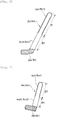
- Fig. 1 is a front view of a vertical wafer boat according to an embodiment
- Fig. 2 is a side elevational view of the vertical wafer boat shown in Fig. 1
- Fig. 3 is a plan view of a top plate of the vertical wafer boat
- Fig. 4 is a sectional view taken along line I-I of Fig. 1
- Fig. 5 is a side elevational view of the support portion of the vertical wafer boat according to the embodiment
- Fig. 6 is a plan view of a support portion forward in a wafer insertion direction
- Fig. 7 is a plan view of a support portion rearward in the wafer insertion direction.
- a vertical wafer boat 1 has front support members 2, 3 and rear support members 4, 5 when viewed from a direction X in which a wafer is inserted, and these support members 2, 3, 4, and 5 are disposed in a vertical direction in parallel with each other.
- the lower ends of the respective support members 2, 3, 4, and 5 stand on a disk-shaped bottom plate 6, and further the upper ends of the respective support members 2, 3, 4, and 5 are supported by a disk-shaped top plate 7.
- a symbol W shown by a virtual line of Fig. 4 shows a position of a wafer mounted on the vertical wafer boat 1, and an arrow X shows an insertion direction into which the wafer W is inserted into the vertical wafer boat 1.
- the respective support members 2, 3, 4, and 5 are composed of support column portions 2b, 3b, 4b, and 5b and a plurality of wafer support portions 2a, 3a, 4a, and 5a which are formed so as to horizontally extend from the side surfaces of these support column portions 2b, 3b, 4b, and 5b, respectively, and the horizontal cross sections including the wafer support portions of the respective support members 2, 3, 4, and 5 are formed in an approximately flexure shape.
- the wafer support portions 2a, 3a, 4a, and 5a in the respective support members 2, 3, 4, and 5 are formed in the number of 50 to 150 pieces in a vertical direction at a pitch of 8 mm.
- the support members 2 and 3 which are positioned forward of the wafer insertion direction, are formed line-symmetrically with respect to a virtual line h connecting the insertion direction X of the wafer W to an insertion center point O of the wafer W, and the extreme ends S2 and S3 of the wafer support portions 2a and 3a are formed in an semi-circular shape when viewed from above it.
- the support members 4 and 5 which are positioned rearward of wafer insertion direction, are formed line- symmetrically with respect to the virtual line h passing through the insertion center point O of the wafer W and extending in the insertion direction X of the wafer W.
- the support members 4 and 5 which are positioned rearward of the wafer insertion direction, are formed approximately linearly toward the insertion center point O of the wafer W, and the wafer support portions 4a and 5a extend straight from the support members 4 and 5 rearward of the wafer insertion direction.
- the extreme ends S4 and S5 of the wafer support portions 4a and 5a formed in a semi-circular shape when viewed from above it.
- the extreme ends S2 and S3 of the wafer support portions 2a and 3a and the extreme ends S4 and S5 of the wafer support portions 4a and 5a are arranged such that they are disposed to the positions of 60% or more to 75% or less of the radius of the wafer W from the center of the wafer.
- Generation of stress can be minimized by disposing the extreme ends S2, S3, S4, and S5 to the predetermined positions, respectively with a result that occurrence of slip of the wafer can be reduced.
- the positions of the extreme ends of the wafer support portions are optimum in the vertical wafer boat in which the four wafer support portions exist and more preferably located from 65% or more to 75% or less in the radius direction of the wafer from the center thereof.
- an opening 7a of the top plate 7 is formed at the center thereof to form a main flow of a gas at the center of the top plate 7 when purification is performed.
- the opening 7a is formed to have a diameter ⁇ A so that the extreme ends S2, S3, S4, and S5 of the wafer support portion 2, 3, 4, and 5 do not project inward of the opening 7a when viewed from the upper surface of the top plate 7. This arrangement is more preferable because it is possible to make it difficult for the extreme ends S2, S3, S4, and S5 of the wafer support portions 2, 3, 4, and 5 projecting in the opening 7a to cause abnormal gas disturbance on the central side of the wafer.
- the opening 7a is preferably formed in a circular shape about the center of the top plate (center of the wafer to be placed), it is not particularly limited thereto and may be formed in other shapes, for example, polygonal shapes such as a square shape, a hexagonal shape, an octagon shape, and the like, an oval shape, a star shape, and a gear shape.
- the outside shape of the top plate 7 is preferably formed in a circular shape ordinarily, it is not particularly limited thereto and may be formed in other shapes, for example, polygonal shapes such as a square shape, a hexagonal shape, an octagonal shape, and the like, an oval shape, an approximately star shape, and a gear shape.
- a slit portion 7b communicating with the opening 7a is formed to the side of the top plate 7 from which the wafer W is inserted.
- the slit portion 7b is formed so that the intermediate point of the slit portion 7b in the width direction thereof is positioned on the virtual line h connecting the insertion direction X of the wafer W to the insertion center point O of the wafer W.
- the width T of the slit portion 7b of the top plate 7 is preferably set to a size of 35% or more to 45% or less of the width of the top plate.
- the width of the top plate 7 means the length thereof in the direction orthogonal to the wafer insertion direction X, and when the top plate 7 is formed in a circular shape, the width of the top plate 7 means the diameter ⁇ D of the top plate.
- a reason why the width T of the slit portion 7b is set 45% or less of the width of the top plate resides in that when the width T exceeds 45%, the strength of the boat is made weak and is not preferable.
- the upper surface corners 2a1 and 3a1 of the wafer support portions 2a and 3a are chamfered up to a position of 40% or more to 60% or less of the length of the wafer support members 2 and 3 from the extreme ends of the wafer support portions 2a and 3a in a support column direction (in a length 11 of 40% or more to 60% or less of the length of the wafer support portions 2a and 3a).
- the upper surface corners 2a2 and 3a2 of the wafer support portions 2a and 3a are formed at an acute angle of 90° or less from the positions where the chamfering is ended to the support column portions 2b and 3b (in a length 12 of 40% or more to 60% or less of the length of the wafer support portions 2a and 3a).
- the upper surface corners 4a1 and 5a1 of the wafer support portions 4a and 5a are chamfered up to a position of 40% or more to 60% or less of the length of the wafer support portions 4a and 5a from the extreme ends of the wafer support portions 4a and 5a in the support column direction (in a length 13 of 40% or more to 60% or less of the length of the wafer support portions 4a and 5a).
- the upper surface corners 4a2 and 5a2 of the wafer support portions 4a and 5a are formed at an acute angle of 90° or less from the positions where the chamfering is ended to the support column portions 4b and 5b (in a length 14 of 40% or more to 60% or less of the length of the wafer support portions 4a and 5a).
- the chamfering of the wafer support portions 2a, 3a, 4a, and 5a is prescribed in view of the balance between suppression of occurrence of slip and the efficiency of generation of a gas turbulent flow generated in the vicinity of the support column portions 2b, 3b, 4b, and 5b of the wafer support portions 2a, 3a, 4a, and 5a.
- the above chamfering includes C chamfering and R chamfering.
- the corners having the acute angle of 90° or less are formed to the upper surfaces of the wafer support portions 2a, 3a, 4a, and 5a from the positions where the chamfering is ended to the support column portions in order to generate a turbulent flow in the vicinity of the support column portions when the gas impinges against the corners.
- sectional shape of the wafer support portions 2, 3, 4, and 5 is not particularly limited and may be a rectangular shape, a square shape, and a triangular shape, and the surfaces other than the upper surface may be a curved surface.
- the area of the opening 7a of the top plate 7 is preferably formed to have an area of 30% or more to 40% or less of the area of the upper surface of the top plate 7.
- a reason why the area of the opening is prescribed as described above is to cause the gas to sufficiently flow to the wafer support portions 2a, 3a, 4a, and 5a located below the top plate 7.
- the area of the opening 7a of the top plate 7 is less than 30% of the area of upper surface of the top plate, since it is difficult to sufficiently supply the gas to the lower portion of the boat, there is a possibility that a purifying effect cannot be sufficiently obtained.
- the area of the opening exceeds 40%, the flow of the gas which passes through the boat from above it to below it, is increased and the gas simply passes through inside of the boat without coming into contact with the support columns and the wafer support portions, there is also a possibility that the purifying effect cannot be sufficiently obtained.
- the width T of the slit portion 7b of the of the top plate 7 is more preferably the same as the interval between the extreme ends S2 and S3 of the support portions on the side where the wafer begins to be inserted.
- the edge of the slit portion 7b overlaps the extreme ends S2 and S3 of the wafer support portions 2a and 3a when viewed from the upper surface of the top plate 7, the abnormal gas disturbance on the central side of the wafer, which is caused by that the extreme ends S2 and S3 of the wafer support portions 2a and 3a project inward of the slit portion 7b, can be securely suppressed.
- a furnace used for the experiment is a ⁇ 300 mm vertical furnace which has a furnace inside diameter of ⁇ 390 mm and a furnace core tube height of 1650 mm and whose outside shape is formed such that top and bottom plate diameters of 330 mm and a boat height of 1200 mm.
- a heat treatment 10 times under the same use condition one evaluation wafer was disposed at the center of the boat (at a fiftieth groove of a groove position from the upper portion of the boat) and was subjected to a heat treatment for evaluation.
- the use condition is such that each vertical wafer boat on which 100 wafers were stacked at 600°C was put into the furnace, the temperature of the wafers was increased between 600°C and 1200°, and the wafers were taken out from the furnace after the temperature thereof was lowered to 600°C. Further, as an evaluation heat treatment, the evaluation wafer was put into the furnace at 600°C and the temperature of it was heated up to 1200°C and held for 10 hours, and thereafter the evaluation wafer was taken out from the furnace after the temperature thereof was lowered to 600°C. In any of the cases, the gas composed of a 100% argon gas was flown in the amount of 15 litters per minute.
- MCL was evaluated using a 12-inch mirror-finished silicon wafer, and the MCL of the wafer was evaluated after the evaluation heat treatment.
- the MCL evaluation was performed to an iron element by an analysis of the ICP-MS method of JIS K 0102-57.4 Standard. A surface portion of 80% of the radius from a center toward an outer peripheral direction was classified as a portion 1, a surface portion outside of the portion 1 was classified as a portion 2, and a portion of the portion 1 added with the portion 2 was classified as a total portion, and the analyzed values of the respective portions were compared with each other. Note that the analysis method was based on the method disclosed in Japanese Patent Application Laid-Open Publication No. 2002-39927 .
- the determination index of the MCL evaluation was classified to three ranks depending on the values of the analysis result, and the MCL was evaluated by the three ranks. More specifically, a portion having an MCL value of 1.0 atoms/cc or more was evaluated as ⁇ , a portion in the range of 0.5 to 1.0 atoms/cc was evaluated as ⁇ , and a portion having an MCL value which was less than 0.5 atoms/cc was evaluated as ⁇ .
- a slip evaluation was performed in such a manner that 100 mirror-finished silicon wafers of 12 inches were stacked on a boat and subjected to a heat treatment once under the use condition described above, and the in-planes of three wafers, i.e., the in-planes of a first, fiftieth, and hundredth wafers from the upper portion of the boat were measured by X-ray topography and evaluated by being compared with the largest slip length which was longest in observed slips.
- the determination index of the slip evaluation was classified to two ranks, and when a maximum slip length exceeding 30 mm existed, it was evaluated as ⁇ , and when a maximum slip length less than 10 mm existed or when a slip itself did not exist, it was evaluated as ⁇ .
Landscapes
- Container, Conveyance, Adherence, Positioning, Of Wafer (AREA)
- Packaging Frangible Articles (AREA)
Description
- The present invention relates to a vertical wafer boat used for the heat treatment of a wafer, and more particularly to a vertical wafer boat having long wafer support portions.
- A wafer used to manufacture a semiconductor device is subjected to a heat treatment, and the heat treatment is performed by accommodating a vertical wafer boat, on which a lot of wafers are placed, in a heat treatment apparatus.
- Incidentally, as the diameter of a wafer is increased recently, since the wafer becomes liable to slip, a countermeasure for the slip is an important problem. As a countermeasure for suppressing slip, for example, Japanese Patent Application Laid-Open Publication No.
2006-080452 - Document
US 2005/0145584 A1 discloses a wafer boat with interference fit wafer supports, such supports being designed for supporting a batch of wafers while minimizing thermal stresses. - The proposed vertical wafer boat will be described based on
Fig. 8 . Note thatFig. 8 shows the vertical wafer boat when the wafer boat is observed from above it therethrough. - In
Fig. 8 , thewafer boat 100 hasfront support members rear support members support members support members - Note that
reference numeral 105, which shows an outer peripheral circle shown inFig. 8 , shows the upper fixed member (top plate) of thewafer boat 100. Further, a symbol W, which is shown by a virtual line, shows a position of a wafer mounted on thewafer boat 100. Further, an arrow X shows a direction in which the wafer W is inserted to thewafer boat 100. - The
respective support members 101 to 104 are composed ofsupport column portions wafer support portions support column portions - Further, the
support members support members - Further, the horizontal cross sections including the wafer support portions of the
support members portions support members - Here, the extreme ends, which face the wafer insertion center of the wafer support
portions 101a and 102a, of thesupport members support members - With this arrangement, since the wafer W is supported by the respective
wafer support portions - Although the vertical wafer boat having the wafer support portions extending to the position of 40 to 60% of the radius of the wafer W described above, i.e., the vertical wafer boat having a so-called long wafer support portions is very effective to minimize deformation of a wafer, the wafer boat has a technical problem in that it cannot securely suppress occurrence of slip of the wafer.
- Further, it is known that as a time passes after the vertical wafer boat begins to be used, metal impurities are deposited on (transferred) to the vertical wafer boat, and it becomes polluted. Accordingly, the vertical wafer boat is periodically subjected to a rinsing or purifying process.
- The purifying process is performed by accommodating the vertical wafer boat, on which no wafer is mounted, in a heat treatment furnace and flowing a purifying gas thereto for a predetermined period of time to diffuse and remove the metal impurities from a surface layer of the vertical wafer boat.
- However, when the vertical wafer boat having the long wafer support portions as described above is purified, since the distance between the wafer support portions disposed to the vertical wafer boat is narrow and further the wafer support portions are long, a technical problem arise in that the purifying process cannot be effectively performed in a short period of time because the purifying gas does not sufficiently reach the vicinities of support columns of the wafer support portions. In particular, the purifying gas is not substituted in a region where it stays, from which a technical problem arises in that the purifying process is insufficiently performed.
- The inventors examined a vertical wafer boat having wafer support portions the length of which is increased not only from a viewpoint of suppression of wafer deformation but also from a viewpoint of minimization of generation of stress caused by the deformation and a viewpoint of a gas flow in the boat.
- As a result, the inventors have conceived the present invention in that when an opening of a top plate of a vertical wafer boat has a particular shape and size and further wafer support portions have a specific disposition and structure, slip of a wafer can be securely suppressed and a purifying process can be effectively performed to the vicinities of support columns of the wafer support members the length of which is increased.
- The present invention was made in view of the above circumstances.
-
US 2005/145584A1 discloses a wafer boat comprising a combination of features falling within the scope of the preamble of Claim 1. Further prior art is known fromJP 11 126 755 A JP 2007 266156A - According to the present invention, there is provided a vertical wafer boat having a top plate, a plurality of support columns each having one end fixed to the top plate and the other end fixed to a bottom plate, and wafer support portions projecting from side surfaces of the support columns in a horizontal direction, wherein the top plate has an opening formed using the center point of a wafer to be mounted as its center and a slit portion communicating with the opening and formed to the insertion side of the wafer, and wherein the slit has a width which is 35% or more to 45% or less of the width of the top plate, the vertical wafer boat characterized in that: the wafer support portions extend to the position of 60% or more to 75% or less of the radius of the wafer from the center of the wafer to be mounted and, further, upper surface corners of the wafer support portions are chamfered up to the position of 40% or more to 60% or less of the length of the wafer support portions from the extreme ends of the wafer support portions toward the direction of the support columns as well as the upper surface corners of the wafer support portions from the positions at which the chamfering is ended to the support columns are formed at an angle of 90° or less.
- It is preferable that the area of the opening of the top plate be 30% or more to 40% or less of the area of upper surface of the top plate and that the slit width of the top plate be the same as the interval between the extreme ends of the two wafer support portions positioned forward of a wafer insertion direction.
- With embodiments of the present invention, there can be obtained a vertical wafer boat which can securely suppress slip of a wafer, by which the purifying efficiency of a purifying process is improved, and which has wafer support portions the length of which is increased.
- To enable a better understanding of the present invention, and to show how the same may be carried into effect, reference will now be made, by way of example only, to the accompanying drawings, in which:-
-
Fig. 1 is a front view of a vertical wafer boat according to an embodiment; -
Fig. 2 is a side elevational view of the vertical wafer boat shown inFig. 1 ; -
Fig. 3 is a plan view of a top plate of the vertical wafer boat; -
Fig. 4 is a sectional view taken along line I-I ofFig. 1 ; -
Fig. 5 is a side elevational view of the support portion of the vertical wafer boat according to the embodiment; -
Fig. 6 is a plan view of a support portion forward in a wafer insertion direction; -
Fig. 7 is a plan view of a support portion rearward in the wafer insertion direction; and -
Fig. 8 is a plan view showing a wafer support portion of a conventional vertical wafer boat. - The vertical wafer boat according to an embodiment of the present invention is described below with reference to
Figs. 1 to 7 . -
Fig. 1 is a front view of a vertical wafer boat according to an embodiment,Fig. 2 is a side elevational view of the vertical wafer boat shown inFig. 1 ,Fig. 3 is a plan view of a top plate of the vertical wafer boat,Fig. 4 is a sectional view taken along line I-I ofFig. 1 ,Fig. 5 is a side elevational view of the support portion of the vertical wafer boat according to the embodiment,Fig. 6 is a plan view of a support portion forward in a wafer insertion direction,Fig. 7 is a plan view of a support portion rearward in the wafer insertion direction. - As shown in
Figs. 1 and 2 , a vertical wafer boat 1 hasfront support members rear support members support members respective support members shaped bottom plate 6, and further the upper ends of therespective support members top plate 7. - Further, arrangements of the
respective support members Fig. 4 . Note that, likewise the case shown inFig. 8 , a symbol W shown by a virtual line ofFig. 4 shows a position of a wafer mounted on the vertical wafer boat 1, and an arrow X shows an insertion direction into which the wafer W is inserted into the vertical wafer boat 1. - The
respective support members support column portions wafer support portions support column portions respective support members - Further, as shown in
Fig. 1 , the wafer supportportions respective support members - Further, the
support members portions - Further, the
support members - Then, the
support members portions support members portions - In the present invention, the extreme ends S2 and S3 of the wafer support
portions portions - Note that, as described above, the positions of the extreme ends of the wafer support portions are optimum in the vertical wafer boat in which the four wafer support portions exist and more preferably located from 65% or more to 75% or less in the radius direction of the wafer from the center thereof.
- Further, an opening 7a of the
top plate 7 is formed at the center thereof to form a main flow of a gas at the center of thetop plate 7 when purification is performed. The opening 7a is formed to have a diameter φA so that the extreme ends S2, S3, S4, and S5 of thewafer support portion top plate 7. This arrangement is more preferable because it is possible to make it difficult for the extreme ends S2, S3, S4, and S5 of thewafer support portions opening 7a to cause abnormal gas disturbance on the central side of the wafer. - Although the
opening 7a is preferably formed in a circular shape about the center of the top plate (center of the wafer to be placed), it is not particularly limited thereto and may be formed in other shapes, for example, polygonal shapes such as a square shape, a hexagonal shape, an octagon shape, and the like, an oval shape, a star shape, and a gear shape. - Further, the outside shape of the
top plate 7 is preferably formed in a circular shape ordinarily, it is not particularly limited thereto and may be formed in other shapes, for example, polygonal shapes such as a square shape, a hexagonal shape, an octagonal shape, and the like, an oval shape, an approximately star shape, and a gear shape. - Further, a
slit portion 7b communicating with theopening 7a is formed to the side of thetop plate 7 from which the wafer W is inserted. Theslit portion 7b is formed so that the intermediate point of theslit portion 7b in the width direction thereof is positioned on the virtual line h connecting the insertion direction X of the wafer W to the insertion center point O of the wafer W. - Further, the width T of the
slit portion 7b of thetop plate 7 is preferably set to a size of 35% or more to 45% or less of the width of the top plate. When thetop plate 7 is formed in a rectangular shape, the width of thetop plate 7 means the length thereof in the direction orthogonal to the wafer insertion direction X, and when thetop plate 7 is formed in a circular shape, the width of thetop plate 7 means the diameter φD of the top plate. - A reason why the width T of the
slit portion 7b is set to 35% or more of the width of the top plate as described above resides in that when the width T of the top plate is less than 35%, a sufficient amount of a gas cannot be secured through thetop plate 7. In contrast, a reason why the width T of theslit portion 7b is set 45% or less of the width of the top plate resides in that when the width T exceeds 45%, the strength of the boat is made weak and is not preferable. - Further, as shown in
Figs. 5 and6 , the upper surface corners 2a1 and 3a1 of thewafer support portions wafer support members wafer support portions wafer support portions - Then, the upper surface corners 2a2 and 3a2 of the
wafer support portions support column portions length 12 of 40% or more to 60% or less of the length of thewafer support portions - Likewise, as shown in
Fig. 7 , the upper surface corners 4a1 and 5a1 of thewafer support portions wafer support portions wafer support portions wafer support portions - Then, the upper surface corners 4a2 and 5a2 of the
wafer support portions support column portions wafer support portions - In the present invention, the chamfering of the
wafer support portions support column portions wafer support portions - That is, when the chamfering is performed from the extreme ends of the
wafer support portions - In contrast, when the chamfering is performed from the extreme ends of the
wafer support portions - Further, the corners having the acute angle of 90° or less are formed to the upper surfaces of the
wafer support portions - When the corners of the upper surfaces of the
wafer support portions - Note that the sectional shape of the
wafer support portions - Further, in the present invention, the area of the
opening 7a of thetop plate 7 is preferably formed to have an area of 30% or more to 40% or less of the area of the upper surface of thetop plate 7. - A reason why the area of the opening is prescribed as described above is to cause the gas to sufficiently flow to the
wafer support portions top plate 7. - Specifically, when the area of the
opening 7a of thetop plate 7 is less than 30% of the area of upper surface of the top plate, since it is difficult to sufficiently supply the gas to the lower portion of the boat, there is a possibility that a purifying effect cannot be sufficiently obtained. In contrast, when the area of the opening exceeds 40%, the flow of the gas which passes through the boat from above it to below it, is increased and the gas simply passes through inside of the boat without coming into contact with the support columns and the wafer support portions, there is also a possibility that the purifying effect cannot be sufficiently obtained. - Further, the width T of the
slit portion 7b of the of thetop plate 7 is more preferably the same as the interval between the extreme ends S2 and S3 of the support portions on the side where the wafer begins to be inserted. - In this case, since the edge of the
slit portion 7b overlaps the extreme ends S2 and S3 of thewafer support portions top plate 7, the abnormal gas disturbance on the central side of the wafer, which is caused by that the extreme ends S2 and S3 of thewafer support portions slit portion 7b, can be securely suppressed. - When a vertical wafer boat of
Figs. 1 to 4 was designed so that the extreme ends ofwafer support portions opening 7a and aslit portion 7b of atop plate 7 when viewed from above thetop plate 7 by changing the length ofwafer support portions support members wafer support portions support members support portions slit portion 7b of thetop plate 7, the parameters of the respective portions were shown by A, B, C, and D, respectively. - A: the ratio of a slit width to the width of a top plate;
- B: the positions of the extreme ends of wafer support portions (a ratio from the center of a wafer to the radius of the wafer);
- C: the chamfering positions of wafer support portions (the ratio of the length from the extreme ends of wafer support portions to the length of the wafer support portions); and
- D: the angle of upper surface corners from the positions where the chamfering of the wafer support portions are ended to support columns. A comparative experiment was performed to vertical wafer boats made changing the conditions of the parameters A, B, C, and D as shown in Table 1 using a method described in the conditions of the comparative experiment.
- The conditions of the comparative example will be described below.
- A furnace used for the experiment is a φ300 mm vertical furnace which has a furnace inside diameter of φ390 mm and a furnace core tube height of 1650 mm and whose outside shape is formed such that top and bottom plate diameters of 330 mm and a boat height of 1200 mm. As the experiment using the furnace, after respective vertical wafer boats were continuously subjected to a
heat treatment 10 times under the same use condition, one evaluation wafer was disposed at the center of the boat (at a fiftieth groove of a groove position from the upper portion of the boat) and was subjected to a heat treatment for evaluation. - The use condition is such that each vertical wafer boat on which 100 wafers were stacked at 600°C was put into the furnace, the temperature of the wafers was increased between 600°C and 1200°, and the wafers were taken out from the furnace after the temperature thereof was lowered to 600°C. Further, as an evaluation heat treatment, the evaluation wafer was put into the furnace at 600°C and the temperature of it was heated up to 1200°C and held for 10 hours, and thereafter the evaluation wafer was taken out from the furnace after the temperature thereof was lowered to 600°C. In any of the cases, the gas composed of a 100% argon gas was flown in the amount of 15 litters per minute.
- MCL was evaluated using a 12-inch mirror-finished silicon wafer, and the MCL of the wafer was evaluated after the evaluation heat treatment. The MCL evaluation was performed to an iron element by an analysis of the ICP-MS method of JIS K 0102-57.4 Standard. A surface portion of 80% of the radius from a center toward an outer peripheral direction was classified as a portion 1, a surface portion outside of the portion 1 was classified as a
portion 2, and a portion of the portion 1 added with theportion 2 was classified as a total portion, and the analyzed values of the respective portions were compared with each other. Note that the analysis method was based on the method disclosed in Japanese Patent Application Laid-Open Publication No.2002-39927 - The determination index of the MCL evaluation was classified to three ranks depending on the values of the analysis result, and the MCL was evaluated by the three ranks. More specifically, a portion having an MCL value of 1.0 atoms/cc or more was evaluated as Δ, a portion in the range of 0.5 to 1.0 atoms/cc was evaluated as ○, and a portion having an MCL value which was less than 0.5 atoms/cc was evaluated as ⊚.
- Further, a slip evaluation was performed in such a manner that 100 mirror-finished silicon wafers of 12 inches were stacked on a boat and subjected to a heat treatment once under the use condition described above, and the in-planes of three wafers, i.e., the in-planes of a first, fiftieth, and hundredth wafers from the upper portion of the boat were measured by X-ray topography and evaluated by being compared with the largest slip length which was longest in observed slips.
- The determination index of the slip evaluation was classified to two ranks, and when a maximum slip length exceeding 30 mm existed, it was evaluated as Δ, and when a maximum slip length less than 10 mm existed or when a slip itself did not exist, it was evaluated as ○.
- It was confirmed from the result of the evaluation by a comparative experiment of Table 1 that occurrence of slip of a wafer could be suppressed and the support portions were entirely purified by setting all the conditions A to D within the predetermined ranges of the present invention.
[Table 1] Parameter (%) Result of MCL Evaluation Slip Evaluation A B C D Portion 1 Portion 2Total Comparative Example 1 30 55 65 90 Δ Δ Δ Δ Example 1 35 60 60 90 ○ ○ ○ ○ Example 2 40 65 50 90 ○ ⊚ ⊚ ○ Example 3 45 75 40 85 ○ ○ ○ ○ Comparative Example 2 50 80 35 90 ○ Δ Δ Δ Conventional Example 40 50 50 100 Δ Δ Δ ○
Claims (3)
- A vertical wafer boat (1) having a top plate (7), a plurality of support columns (2b, 3b, 4b, 5b) each having one end fixed to the top plate and the other end fixed to a bottom plate (6), and wafer support portions (2a, 3a, 4a, 5a) projecting from side surfaces of the support columns in a horizontal direction,
wherein the top plate has an opening (7a) formed using the center point (O) of a wafer (W) to be mounted as its center and a slit portion (7b) communicating with the opening (7a) and formed to the insertion side of the wafer, and
wherein the slit has a width (T) which is 35% or more to 45% or less of the width (ΦD) of the top plate,
the vertical wafer boat characterized in that:the wafer support portions (2a, 3a, 4a, 5a) extend to the position of 60% or more to 75% or less of the radius of the wafer (W) from the center (O) of the wafer to be mounted; and,further, upper surface corners (2a1, 3a1, 4a1, 5a1) of the wafer support portions (2a, 3a, 4a, 5a) are chamfered up to the position of 40% or more to 60% or less of the length of the wafer support portions from the extreme ends of thewafer support portions toward the direction of the support columns (2b, 3b, 4b, 5b) as well as the upper surface corners (2a2, 3a2, 4a2, 5a2) of the wafer support portions (2a, 3a, 4a, 5a) from the positions at which the chamfering is ended to the support columns are formed at an angle of 90° or less. - The vertical wafer boat according to claim 1, characterized in that the area of the opening (7a) of the top plate (7) is 30% or more to 40% or less of the area of upper surface of the top plate.
- The vertical wafer boat according to claim 1 or 2, characterized in that the slit width (T) of the top plate (7) is the same as the interval between the extreme ends of the two wafer support portions (2a, 3a) positioned forward of a wafer insertion direction (X).
Applications Claiming Priority (2)
| Application Number | Priority Date | Filing Date | Title |
|---|---|---|---|
| JP2007266479A JP5184040B2 (en) | 2007-10-12 | 2007-10-12 | Vertical wafer boat |
| PCT/JP2008/068275 WO2009048068A1 (en) | 2007-10-12 | 2008-10-08 | Vertical wafer boat |
Publications (3)
| Publication Number | Publication Date |
|---|---|
| EP2200072A1 EP2200072A1 (en) | 2010-06-23 |
| EP2200072A4 EP2200072A4 (en) | 2011-07-06 |
| EP2200072B1 true EP2200072B1 (en) | 2018-03-14 |
Family
ID=40549212
Family Applications (1)
| Application Number | Title | Priority Date | Filing Date |
|---|---|---|---|
| EP08836871.7A Active EP2200072B1 (en) | 2007-10-12 | 2008-10-08 | Vertical wafer boat |
Country Status (3)
| Country | Link |
|---|---|
| EP (1) | EP2200072B1 (en) |
| JP (1) | JP5184040B2 (en) |
| WO (1) | WO2009048068A1 (en) |
Families Citing this family (5)
| Publication number | Priority date | Publication date | Assignee | Title |
|---|---|---|---|---|
| US9530675B2 (en) * | 2012-09-19 | 2016-12-27 | Stmicroelectronics Pte Ltd | Wafer handling station including cassette members with lateral wafer confining brackets and associated methods |
| JP6454122B2 (en) * | 2014-10-07 | 2019-01-16 | 住友ゴム工業株式会社 | Prediction method of block stiffness |
| JP6770461B2 (en) | 2017-02-21 | 2020-10-14 | クアーズテック株式会社 | Vertical wafer boat |
| KR102679829B1 (en) * | 2019-06-20 | 2024-07-01 | 주식회사 원익아이피에스 | Boat for semiconductor processing |
| CN111370355B (en) * | 2019-12-03 | 2025-10-28 | 北京粤海金半导体技术有限公司 | Wafer receiving device and wafer etching method |
Family Cites Families (9)
| Publication number | Priority date | Publication date | Assignee | Title |
|---|---|---|---|---|
| JPH11126755A (en) * | 1997-10-22 | 1999-05-11 | Sumitomo Metal Ind Ltd | Method for manufacturing boat for semiconductor heat treatment |
| US5931666A (en) * | 1998-02-27 | 1999-08-03 | Saint-Gobain Industrial Ceramics, Inc. | Slip free vertical rack design having rounded horizontal arms |
| JP3511466B2 (en) * | 1998-05-22 | 2004-03-29 | 東芝セラミックス株式会社 | Semiconductor wafer heat treatment member and jig using the same |
| JP2001168175A (en) * | 1999-12-07 | 2001-06-22 | Semiconductor Leading Edge Technologies Inc | Heat treatment substrate holder, substrate heat treatment apparatus, and substrate heat treatment method |
| JP2004119538A (en) * | 2002-09-25 | 2004-04-15 | Hitachi Kokusai Electric Inc | Semiconductor manufacturing equipment |
| US20050145584A1 (en) * | 2004-01-06 | 2005-07-07 | Buckley Richard F. | Wafer boat with interference fit wafer supports |
| US20050205502A1 (en) * | 2004-03-18 | 2005-09-22 | Brown Steven A | Rails for semiconductor wafer carriers |
| JP4486867B2 (en) * | 2004-09-13 | 2010-06-23 | コバレントマテリアル株式会社 | Vertical wafer boat |
| JP2007266156A (en) | 2006-03-28 | 2007-10-11 | Covalent Materials Corp | Wafer support for vertical wafer boat |
-
2007
- 2007-10-12 JP JP2007266479A patent/JP5184040B2/en active Active
-
2008
- 2008-10-08 WO PCT/JP2008/068275 patent/WO2009048068A1/en not_active Ceased
- 2008-10-08 EP EP08836871.7A patent/EP2200072B1/en active Active
Non-Patent Citations (1)
| Title |
|---|
| None * |
Also Published As
| Publication number | Publication date |
|---|---|
| JP2009099576A (en) | 2009-05-07 |
| JP5184040B2 (en) | 2013-04-17 |
| WO2009048068A1 (en) | 2009-04-16 |
| EP2200072A4 (en) | 2011-07-06 |
| EP2200072A1 (en) | 2010-06-23 |
Similar Documents
| Publication | Publication Date | Title |
|---|---|---|
| US7484958B2 (en) | Vertical boat for heat treatment and method for producing the same | |
| EP1256975B1 (en) | Vertical type wafer supporting jig | |
| US6171400B1 (en) | Vertical semiconductor wafer carrier | |
| EP2200072A1 (en) | Vertical wafer boat | |
| KR102074837B1 (en) | Vertical wafer boat | |
| US6099645A (en) | Vertical semiconductor wafer carrier with slats | |
| KR100235078B1 (en) | Wafer boat for vertical diffusion and vapor growth furnace | |
| KR101978560B1 (en) | Vertical wafer boat | |
| US6939132B2 (en) | Semiconductor workpiece apparatus | |
| KR101990533B1 (en) | Batch type semiconductor manufacturing device | |
| US20070082314A1 (en) | Low contact sic boat for silicon nitride stress reduction | |
| EP4163425B1 (en) | Heat treatment method for silicon wafer using horizontal heat treatment furnace | |
| GB2307732A (en) | Boat for vertical diffusion furnace | |
| JP2006128316A (en) | Vertical boat for heat treatment and heat treatment method | |
| JP3650423B2 (en) | Wafer boat | |
| JP2009076621A (en) | Vertical boat for heat treatment | |
| JP2006005271A (en) | Heat treatment jig and semiconductor wafer heat treatment method | |
| JP2007036105A (en) | Silicon wafer susceptor | |
| JP2006093283A (en) | Wafer support | |
| JPH1140659A (en) | Vertical boat for heat treatment of semiconductor wafers | |
| JP2005311291A (en) | Vertical boat | |
| CN220651977U (en) | Wafer boat and semiconductor device | |
| CN221352691U (en) | Heat treatment boat for vertical heat treatment furnace and vertical heat treatment furnace | |
| JP2005328008A (en) | Vertical boat for heat-treating semiconductor wafer, and heat treatment method | |
| JP2006080125A (en) | Vertical boat for heat treatment of semiconductor wafers |
Legal Events
| Date | Code | Title | Description |
|---|---|---|---|
| PUAI | Public reference made under article 153(3) epc to a published international application that has entered the european phase |
Free format text: ORIGINAL CODE: 0009012 |
|
| 17P | Request for examination filed |
Effective date: 20100330 |
|
| AK | Designated contracting states |
Kind code of ref document: A1 Designated state(s): AT BE BG CH CY CZ DE DK EE ES FI FR GB GR HR HU IE IS IT LI LT LU LV MC MT NL NO PL PT RO SE SI SK TR |
|
| AX | Request for extension of the european patent |
Extension state: AL BA MK RS |
|
| DAX | Request for extension of the european patent (deleted) | ||
| A4 | Supplementary search report drawn up and despatched |
Effective date: 20110608 |
|
| RIC1 | Information provided on ipc code assigned before grant |
Ipc: H01L 21/31 20060101ALI20110531BHEP Ipc: H01L 21/68 20060101ALI20110531BHEP Ipc: H01L 21/683 20060101ALI20110531BHEP Ipc: H01L 21/205 20060101ALI20110531BHEP Ipc: H01L 21/22 20060101AFI20090507BHEP Ipc: H01L 21/324 20060101ALI20110531BHEP |
|
| RAP1 | Party data changed (applicant data changed or rights of an application transferred) |
Owner name: COORSTEK KK |
|
| GRAP | Despatch of communication of intention to grant a patent |
Free format text: ORIGINAL CODE: EPIDOSNIGR1 |
|
| INTG | Intention to grant announced |
Effective date: 20171128 |
|
| GRAS | Grant fee paid |
Free format text: ORIGINAL CODE: EPIDOSNIGR3 |
|
| GRAA | (expected) grant |
Free format text: ORIGINAL CODE: 0009210 |
|
| AK | Designated contracting states |
Kind code of ref document: B1 Designated state(s): AT BE BG CH CY CZ DE DK EE ES FI FR GB GR HR HU IE IS IT LI LT LU LV MC MT NL NO PL PT RO SE SI SK TR |
|
| REG | Reference to a national code |
Ref country code: GB Ref legal event code: FG4D |
|
| REG | Reference to a national code |
Ref country code: CH Ref legal event code: EP Ref country code: AT Ref legal event code: REF Ref document number: 979631 Country of ref document: AT Kind code of ref document: T Effective date: 20180315 |
|
| REG | Reference to a national code |
Ref country code: IE Ref legal event code: FG4D |
|
| REG | Reference to a national code |
Ref country code: DE Ref legal event code: R096 Ref document number: 602008054452 Country of ref document: DE |
|
| REG | Reference to a national code |
Ref country code: NL Ref legal event code: MP Effective date: 20180314 |
|
| REG | Reference to a national code |
Ref country code: LT Ref legal event code: MG4D |
|
| PG25 | Lapsed in a contracting state [announced via postgrant information from national office to epo] |
Ref country code: HR Free format text: LAPSE BECAUSE OF FAILURE TO SUBMIT A TRANSLATION OF THE DESCRIPTION OR TO PAY THE FEE WITHIN THE PRESCRIBED TIME-LIMIT Effective date: 20180314 Ref country code: CY Free format text: LAPSE BECAUSE OF FAILURE TO SUBMIT A TRANSLATION OF THE DESCRIPTION OR TO PAY THE FEE WITHIN THE PRESCRIBED TIME-LIMIT Effective date: 20180314 Ref country code: FI Free format text: LAPSE BECAUSE OF FAILURE TO SUBMIT A TRANSLATION OF THE DESCRIPTION OR TO PAY THE FEE WITHIN THE PRESCRIBED TIME-LIMIT Effective date: 20180314 Ref country code: NO Free format text: LAPSE BECAUSE OF FAILURE TO SUBMIT A TRANSLATION OF THE DESCRIPTION OR TO PAY THE FEE WITHIN THE PRESCRIBED TIME-LIMIT Effective date: 20180614 Ref country code: ES Free format text: LAPSE BECAUSE OF FAILURE TO SUBMIT A TRANSLATION OF THE DESCRIPTION OR TO PAY THE FEE WITHIN THE PRESCRIBED TIME-LIMIT Effective date: 20180314 Ref country code: LT Free format text: LAPSE BECAUSE OF FAILURE TO SUBMIT A TRANSLATION OF THE DESCRIPTION OR TO PAY THE FEE WITHIN THE PRESCRIBED TIME-LIMIT Effective date: 20180314 |
|
| REG | Reference to a national code |
Ref country code: AT Ref legal event code: MK05 Ref document number: 979631 Country of ref document: AT Kind code of ref document: T Effective date: 20180314 |
|
| PG25 | Lapsed in a contracting state [announced via postgrant information from national office to epo] |
Ref country code: LV Free format text: LAPSE BECAUSE OF FAILURE TO SUBMIT A TRANSLATION OF THE DESCRIPTION OR TO PAY THE FEE WITHIN THE PRESCRIBED TIME-LIMIT Effective date: 20180314 Ref country code: SE Free format text: LAPSE BECAUSE OF FAILURE TO SUBMIT A TRANSLATION OF THE DESCRIPTION OR TO PAY THE FEE WITHIN THE PRESCRIBED TIME-LIMIT Effective date: 20180314 Ref country code: BG Free format text: LAPSE BECAUSE OF FAILURE TO SUBMIT A TRANSLATION OF THE DESCRIPTION OR TO PAY THE FEE WITHIN THE PRESCRIBED TIME-LIMIT Effective date: 20180614 Ref country code: GR Free format text: LAPSE BECAUSE OF FAILURE TO SUBMIT A TRANSLATION OF THE DESCRIPTION OR TO PAY THE FEE WITHIN THE PRESCRIBED TIME-LIMIT Effective date: 20180615 |
|
| REG | Reference to a national code |
Ref country code: FR Ref legal event code: PLFP Year of fee payment: 11 |
|
| PG25 | Lapsed in a contracting state [announced via postgrant information from national office to epo] |
Ref country code: IT Free format text: LAPSE BECAUSE OF FAILURE TO SUBMIT A TRANSLATION OF THE DESCRIPTION OR TO PAY THE FEE WITHIN THE PRESCRIBED TIME-LIMIT Effective date: 20180314 Ref country code: NL Free format text: LAPSE BECAUSE OF FAILURE TO SUBMIT A TRANSLATION OF THE DESCRIPTION OR TO PAY THE FEE WITHIN THE PRESCRIBED TIME-LIMIT Effective date: 20180314 Ref country code: RO Free format text: LAPSE BECAUSE OF FAILURE TO SUBMIT A TRANSLATION OF THE DESCRIPTION OR TO PAY THE FEE WITHIN THE PRESCRIBED TIME-LIMIT Effective date: 20180314 Ref country code: EE Free format text: LAPSE BECAUSE OF FAILURE TO SUBMIT A TRANSLATION OF THE DESCRIPTION OR TO PAY THE FEE WITHIN THE PRESCRIBED TIME-LIMIT Effective date: 20180314 Ref country code: PL Free format text: LAPSE BECAUSE OF FAILURE TO SUBMIT A TRANSLATION OF THE DESCRIPTION OR TO PAY THE FEE WITHIN THE PRESCRIBED TIME-LIMIT Effective date: 20180314 |
|
| PG25 | Lapsed in a contracting state [announced via postgrant information from national office to epo] |
Ref country code: SK Free format text: LAPSE BECAUSE OF FAILURE TO SUBMIT A TRANSLATION OF THE DESCRIPTION OR TO PAY THE FEE WITHIN THE PRESCRIBED TIME-LIMIT Effective date: 20180314 Ref country code: AT Free format text: LAPSE BECAUSE OF FAILURE TO SUBMIT A TRANSLATION OF THE DESCRIPTION OR TO PAY THE FEE WITHIN THE PRESCRIBED TIME-LIMIT Effective date: 20180314 Ref country code: CZ Free format text: LAPSE BECAUSE OF FAILURE TO SUBMIT A TRANSLATION OF THE DESCRIPTION OR TO PAY THE FEE WITHIN THE PRESCRIBED TIME-LIMIT Effective date: 20180314 |
|
| REG | Reference to a national code |
Ref country code: DE Ref legal event code: R097 Ref document number: 602008054452 Country of ref document: DE |
|
| PG25 | Lapsed in a contracting state [announced via postgrant information from national office to epo] |
Ref country code: PT Free format text: LAPSE BECAUSE OF FAILURE TO SUBMIT A TRANSLATION OF THE DESCRIPTION OR TO PAY THE FEE WITHIN THE PRESCRIBED TIME-LIMIT Effective date: 20180716 |
|
| PLBE | No opposition filed within time limit |
Free format text: ORIGINAL CODE: 0009261 |
|
| STAA | Information on the status of an ep patent application or granted ep patent |
Free format text: STATUS: NO OPPOSITION FILED WITHIN TIME LIMIT |
|
| PG25 | Lapsed in a contracting state [announced via postgrant information from national office to epo] |
Ref country code: DK Free format text: LAPSE BECAUSE OF FAILURE TO SUBMIT A TRANSLATION OF THE DESCRIPTION OR TO PAY THE FEE WITHIN THE PRESCRIBED TIME-LIMIT Effective date: 20180314 |
|
| 26N | No opposition filed |
Effective date: 20181217 |
|
| PG25 | Lapsed in a contracting state [announced via postgrant information from national office to epo] |
Ref country code: SI Free format text: LAPSE BECAUSE OF FAILURE TO SUBMIT A TRANSLATION OF THE DESCRIPTION OR TO PAY THE FEE WITHIN THE PRESCRIBED TIME-LIMIT Effective date: 20180314 |
|
| REG | Reference to a national code |
Ref country code: CH Ref legal event code: PL |
|
| GBPC | Gb: european patent ceased through non-payment of renewal fee |
Effective date: 20181008 |
|
| REG | Reference to a national code |
Ref country code: BE Ref legal event code: MM Effective date: 20181031 |
|
| PG25 | Lapsed in a contracting state [announced via postgrant information from national office to epo] |
Ref country code: LU Free format text: LAPSE BECAUSE OF NON-PAYMENT OF DUE FEES Effective date: 20181008 Ref country code: MC Free format text: LAPSE BECAUSE OF FAILURE TO SUBMIT A TRANSLATION OF THE DESCRIPTION OR TO PAY THE FEE WITHIN THE PRESCRIBED TIME-LIMIT Effective date: 20180314 |
|
| REG | Reference to a national code |
Ref country code: IE Ref legal event code: MM4A |
|
| PG25 | Lapsed in a contracting state [announced via postgrant information from national office to epo] |
Ref country code: LI Free format text: LAPSE BECAUSE OF NON-PAYMENT OF DUE FEES Effective date: 20181031 Ref country code: CH Free format text: LAPSE BECAUSE OF NON-PAYMENT OF DUE FEES Effective date: 20181031 Ref country code: BE Free format text: LAPSE BECAUSE OF NON-PAYMENT OF DUE FEES Effective date: 20181031 |
|
| PG25 | Lapsed in a contracting state [announced via postgrant information from national office to epo] |
Ref country code: GB Free format text: LAPSE BECAUSE OF NON-PAYMENT OF DUE FEES Effective date: 20181008 Ref country code: IE Free format text: LAPSE BECAUSE OF NON-PAYMENT OF DUE FEES Effective date: 20181008 |
|
| PG25 | Lapsed in a contracting state [announced via postgrant information from national office to epo] |
Ref country code: MT Free format text: LAPSE BECAUSE OF NON-PAYMENT OF DUE FEES Effective date: 20181008 |
|
| PG25 | Lapsed in a contracting state [announced via postgrant information from national office to epo] |
Ref country code: TR Free format text: LAPSE BECAUSE OF FAILURE TO SUBMIT A TRANSLATION OF THE DESCRIPTION OR TO PAY THE FEE WITHIN THE PRESCRIBED TIME-LIMIT Effective date: 20180314 |
|
| PG25 | Lapsed in a contracting state [announced via postgrant information from national office to epo] |
Ref country code: HU Free format text: LAPSE BECAUSE OF FAILURE TO SUBMIT A TRANSLATION OF THE DESCRIPTION OR TO PAY THE FEE WITHIN THE PRESCRIBED TIME-LIMIT; INVALID AB INITIO Effective date: 20081008 |
|
| PG25 | Lapsed in a contracting state [announced via postgrant information from national office to epo] |
Ref country code: IS Free format text: LAPSE BECAUSE OF FAILURE TO SUBMIT A TRANSLATION OF THE DESCRIPTION OR TO PAY THE FEE WITHIN THE PRESCRIBED TIME-LIMIT Effective date: 20180714 |
|
| REG | Reference to a national code |
Ref country code: DE Ref legal event code: R081 Ref document number: 602008054452 Country of ref document: DE Owner name: COORSTEK GK, JP Free format text: FORMER OWNER: COORSTEK KK, TOKIO/TOKYO, JP |
|
| PGFP | Annual fee paid to national office [announced via postgrant information from national office to epo] |
Ref country code: FR Payment date: 20250908 Year of fee payment: 18 |
|
| REG | Reference to a national code |
Ref country code: DE Ref legal event code: R079 Ref document number: 602008054452 Country of ref document: DE Free format text: PREVIOUS MAIN CLASS: H01L0021220000 Ipc: H10P0032100000 |
|
| PGFP | Annual fee paid to national office [announced via postgrant information from national office to epo] |
Ref country code: DE Payment date: 20250902 Year of fee payment: 18 |