EP2200060A1 - Cellule de distribution électrique moyenne tension - Google Patents
Cellule de distribution électrique moyenne tension Download PDFInfo
- Publication number
- EP2200060A1 EP2200060A1 EP09354042A EP09354042A EP2200060A1 EP 2200060 A1 EP2200060 A1 EP 2200060A1 EP 09354042 A EP09354042 A EP 09354042A EP 09354042 A EP09354042 A EP 09354042A EP 2200060 A1 EP2200060 A1 EP 2200060A1
- Authority
- EP
- European Patent Office
- Prior art keywords
- current
- parts
- cell according
- electrical distribution
- distribution cell
- Prior art date
- Legal status (The legal status is an assumption and is not a legal conclusion. Google has not performed a legal analysis and makes no representation as to the accuracy of the status listed.)
- Granted
Links
- 238000000926 separation method Methods 0.000 claims abstract description 9
- 238000005516 engineering process Methods 0.000 claims description 5
- CIWBSHSKHKDKBQ-JLAZNSOCSA-N Ascorbic acid Chemical compound OC[C@H](O)[C@H]1OC(=O)C(O)=C1O CIWBSHSKHKDKBQ-JLAZNSOCSA-N 0.000 description 2
- 230000004888 barrier function Effects 0.000 description 1
- 230000015556 catabolic process Effects 0.000 description 1
- 238000003745 diagnosis Methods 0.000 description 1
- 230000005684 electric field Effects 0.000 description 1
- 238000009413 insulation Methods 0.000 description 1
- 230000007704 transition Effects 0.000 description 1
Images


Classifications
-
- H—ELECTRICITY
- H01—ELECTRIC ELEMENTS
- H01H—ELECTRIC SWITCHES; RELAYS; SELECTORS; EMERGENCY PROTECTIVE DEVICES
- H01H31/00—Air-break switches for high tension without arc-extinguishing or arc-preventing means
- H01H31/003—Earthing switches
-
- H—ELECTRICITY
- H01—ELECTRIC ELEMENTS
- H01H—ELECTRIC SWITCHES; RELAYS; SELECTORS; EMERGENCY PROTECTIVE DEVICES
- H01H33/00—High-tension or heavy-current switches with arc-extinguishing or arc-preventing means
- H01H33/60—Switches wherein the means for extinguishing or preventing the arc do not include separate means for obtaining or increasing flow of arc-extinguishing fluid
- H01H33/66—Vacuum switches
- H01H33/666—Operating arrangements
- H01H2033/6668—Operating arrangements with a plurality of interruptible circuit paths in single vacuum chamber
-
- H—ELECTRICITY
- H01—ELECTRIC ELEMENTS
- H01H—ELECTRIC SWITCHES; RELAYS; SELECTORS; EMERGENCY PROTECTIVE DEVICES
- H01H31/00—Air-break switches for high tension without arc-extinguishing or arc-preventing means
- H01H31/26—Air-break switches for high tension without arc-extinguishing or arc-preventing means with movable contact that remains electrically connected to one line in open position of switch
- H01H31/32—Air-break switches for high tension without arc-extinguishing or arc-preventing means with movable contact that remains electrically connected to one line in open position of switch with rectilinearly-movable contact
-
- H—ELECTRICITY
- H01—ELECTRIC ELEMENTS
- H01H—ELECTRIC SWITCHES; RELAYS; SELECTORS; EMERGENCY PROTECTIVE DEVICES
- H01H33/00—High-tension or heavy-current switches with arc-extinguishing or arc-preventing means
- H01H33/60—Switches wherein the means for extinguishing or preventing the arc do not include separate means for obtaining or increasing flow of arc-extinguishing fluid
- H01H33/66—Vacuum switches
- H01H33/666—Operating arrangements
- H01H33/6662—Operating arrangements using bistable electromagnetic actuators, e.g. linear polarised electromagnetic actuators
Definitions
- the present invention relates to a medium voltage electrical distribution cell intended to be interposed between two parts of an electrical circuit so as to provide the functions respectively of current flow between the two parts, of interruption of the current between the two parts, of severing the voltage and grounding of one of the parts of said circuit.
- the vacuum bulbs are used to perform the switch and breaker functions while the air or gas insulated devices are most often used to perform the functions of sectioning or switching. Earth.
- These functions can be combined in different ways to realize functional units providing both power interruption, sectioning and grounding functions.
- a functional unit consisting of a three-position switchgear respectively performing the functions switch, disconnector and earthing switch or a functional unit consisting of a switch-disconnector combined with a disconnector earth, or a functional unit consisting of a two-position switch including grounding combined with a switch or circuit breaker.
- a functional unit consisting of the combination of three devices respectively performing the functions of disconnector, earthing switch and switch.
- the present invention aims to provide a medium voltage electrical distribution cell for performing at least the circuit breaker (switch) and disconnector functions by means of insulation technology using the vacuum so as to eliminate the use of gas, while maintaining a certain compactness of the cell.
- the subject of the present invention is an electrical distribution cell of the kind mentioned above, this cell being characterized in that the current-passing, interruption and sectioning functions of the above-mentioned voltage are realized in vacuum, and in that it further comprises an additional separation means placed in the ground connection circuit, said means being able to add an additional sectioning gap in the earth circuit in the transit position. current and interruption of the current and to remove this additional sectioning interval in the disconnected position of the voltage between the two parts and during the grounding of one of the aforementioned parts.
- the above grounding function is also performed in a vacuum.
- this cell comprises a switch (or circuit breaker) with three positions, respectively a position for passing the current between the two parts, a position for interrupting the current and for disconnecting the voltage between the two parts and a position
- This switch / circuit breaker is housed in a vacuum interrupter.
- this additional separation means is realized with technology of cut in the air, in the gas, in the oil or in the vacuum.
- this bulb comprises an envelope inside which are mounted a first fixed contact electrically connected to the aforesaid first portion of current, a movable contact electrically connected to the aforementioned second circuit part and a second fixed contact which works either as a floating screen or as a contact, and electrically connected to ground.
- the additional separation means comprises a switch to connect or not the second fixed contact to ground.
- the aforementioned first circuit portion is a busbar while the second circuit portion is a cable.
- the second fixed contact is located substantially in the center of the bulb.
- this cell comprises means for detecting the leakage current in the bulb (s). This makes it possible to detect a loss of vacuum, to make a diagnosis of the vacuum level, or to diagnose a loss of tightness of the bulb.
- this means comprises means for continuously measuring the voltage or current flowing through the second fixed contact.
- a medium voltage distribution cell C intended to be placed between a busbar 1 and a cable 2 to ensure between these two elements, or the passage of the current (position a on the figure 1 ), either an interruption of the current following a cut, or a disconnection of the voltage (b), or an earthing of the (of) cables (position c).
- This cell C comprises a vacuum interrupter A and a connection circuit 3 to earth T comprising an air switch (or switch) 4.
- This bulb A houses a circuit breaker 5 which can take three different positions, namely a service position (as shown in FIG.
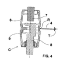
- FIG 2 allowing the passage of the current of service, an open position following a power failure ( figure 3 ), a sectioning position ( fig.4 ) and a grounding position ( fig.5 ).
- the switcher 4 can take two positions (e, f on the figure 1 ), namely a first position e in which it electrically connects the connection point R to the earth of the bulb, to the ground T, and a position (f) in which it interposes between this connection point R and the ground T, an additional sectioning interval I.
- said bulb A comprises an enclosure 6 of substantially cylindrical shape filled with vacuum and housing a first fixed contact 7 electrically connected to the busbar, a movable contact 8 electrically connected to the cable and a second fixed contact 9 electrically connected by the intermediate of the aforementioned connection point R at the aforementioned switch 4, said switch being able to connect the aforementioned connection point R to T.
- the operation of the aforementioned distribution cell will be described in the following with reference to the figures.
- the bulb A In the position illustrated on the figure 2 , or service position, the bulb A is in the closed position to allow the passage of the service current.
- the switch 4 is in the open position.
- the first fixed contact 7 and the movable contact 8 are separated, the passage of the current is interrupted.
- the transition from position a to position b corresponds to an opening of the electric circuit associated with a power failure.
- the use of bulb A in these two positions is conventional.
- the second fixed contact 9 inside the bulb A behaves like a floating screen. The fact that this screen is floating facilitates the dielectric strength during the cutoff phase by reducing the risk of dielectric breakdown.
- the cell On the figure 4 the cell is in the so-called sectioning position. The closing of the switch 4 has been achieved, causing the grounding of the second fixed contact 9. As a result, the electric field inside the bulb changes drastically. A virtual barrier now prevents direct boots between contacts.
- the bulb then functions as a disconnector.
- the earthing switch in the closed position strengthens the sectioning function in the bulb.
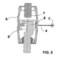
- the moving contact 8 has been brought into contact with the second fixed contact 9 of the bulb A.
- the cell is then in the grounding position. Empty technology makes it possible to reliably achieve the closing power.
- the invention is not limited to the embodiment described and illustrated which has been given by way of example.
- the switchgear making the interruption of the current inside the bulb can be a switch or a circuit breaker.
- the different functions can be placed in different bulbs, one for each function.
Landscapes
- Gas-Insulated Switchgears (AREA)
- High-Tension Arc-Extinguishing Switches Without Spraying Means (AREA)
- Emergency Protection Circuit Devices (AREA)
Abstract
Description
- La présente invention concerne une cellule de distribution électrique moyenne tension destinée à être interposée entre deux parties d'un circuit électrique de manière à assurer les fonctions respectivement de passage du courant entre les deux parties, d'interruption du courant entre les deux parties, de sectionnement de la tension et de mise à la terre de l'une des parties dudit circuit.
- Dans les cellules de distribution électriques connues, les ampoules à vide sont utilisées pour réaliser les fonctions interrupteur et disjoncteur tandis que les dispositifs à isolation dans l'air ou dans le gaz sont le plus souvent utilisés pour réaliser les fonctions de sectionnement ou de mise à la terre.
Ces fonctions peuvent être combinées de différentes manières afin de réaliser des unités fonctionnelles assurant à la fois les fonctions d'interruption du courant, de sectionnement et de mise à la terre.
Ainsi, on connaît une unité fonctionnelle constituée d'un appareil de coupure à trois positions, réalisant respectivement les fonctions interrupteur, sectionneur et sectionneur de terre ou bien une unité fonctionnelle constituée d'un interrupteur-sectionneur combiné à un sectionneur de terre, ou bien une unité fonctionnelle constituée par un sectionneur deux positions comprenant la mise à la terre combinée à un interrupteur ou un disjoncteur. Et l'on connaît également par exemple, une unité fonctionnelle constituée par la combinaison de trois dispositifs réalisant respectivement les fonctions de sectionneur, sectionneur de terre et interrupteur. - La présente invention a pour but de réaliser une cellule de distribution électrique moyenne tension permettant de réaliser au moins les fonctions disjoncteur (interrupteur) et sectionneur au moyen de la technologie d'isolation utilisant le vide de manière à supprimer l'utilisation du gaz, tout en maintenant une certaine compacité de la cellule.
- A cet effet, la présente invention a pour objet une cellule de distribution électrique du genre précédemment mentionné, cette cellule étant caractérisée en ce que les fonctions de passage du courant, d'interruption et de sectionnement de la tension précitées, sont réalisées dans le vide, et en ce qu'il comporte en outre un moyen de séparation supplémentaire placé dans le circuit de raccordement à la terre, ledit moyen étant apte à ajouter un intervalle de sectionnement supplémentaire dans le circuit de terre dans la position de passage du courant et d'interruption du courant et à supprimer cet intervalle de sectionnement supplémentaire en position de sectionnement de la tension entre les deux parties et lors de la mise à la terre de l'une des parties précitées.
- Selon une caractéristique particulière, la fonction de mise à la terre précitée est également réalisée dans le vide.
- Selon une caractéristique particulière, cette cellule comporte un interrupteur (ou disjoncteur) à trois positions, respectivement une position de passage du courant entre les deux parties, une position d'interruption du courant et de sectionnement de la tension entre les deux parties et une position de mise à la terre, cet interrupteur/disjoncteur étant logé dans une ampoule à vide.
- Selon une caractéristique particulière, ce moyen de séparation supplémentaire est réalisé à technologie de coupure dans l'air, dans le gaz, dans l'huile ou dans le vide.
- Selon une autre caractéristique, cette ampoule comporte une enveloppe à l'intérieur de laquelle sont montés un premier contact fixe relié électriquement à la première partie précitée de courant, un contact mobile relié électriquement à la seconde partie de circuit précité et un deuxième contact fixe qui fonctionne soit comme écran flottant soit comme contact, et relié électriquement à la masse.
- Selon une autre caractéristique, le moyen de séparation supplémentaire comporte un aiguilleur permettant de relier ou non le second contact fixe à la masse.
- Selon une autre caractéristique, la première partie de circuit précitée est un jeu de barre tandis que la seconde partie de circuit précitée est un câble.
- Selon une autre caractéristique, le second contact fixe est situé sensiblement au centre de l'ampoule.
- Selon une autre caractéristique, cette cellule comporte un moyen de détection du courant de fuite dans l'(les) ampoule(s). Ceci permet de détecter une perte de vide, de faire un diagnostique du niveau de vide, ou encore de diagnostiquer une perte d'étanchéité de l'ampoule.
- Selon une autre caractéristique, ce moyen comporte un moyen de mesure en continu de la tension ou du courant traversant le second contact fixe.
- Mais d'autres avantages et caractéristiques de l'invention apparaîtront mieux dans la description détaillée qui suit et se réfère aux dessins annexés donnés uniquement à titre d'exemple et dans lesquels :
- La
figure 1 est une représentation schématique d'une cellule de distribution moyenne tension selon l'invention, - Les
figures 2 à 5 illustrent, dans une vue en coupe, une cellule de distribution selon une réalisation particulière de l'invention, respectivement dans une position fermée permettant le passage du courant, dans une position d'ouverture suite à une coupure, dans une position de sectionnement, et dans une position de mise à la terre. - Sur les
figures 1 à 5 , est illustrée une cellule de distribution moyenne tension C selon l'invention, destinée à être placée entre un jeu de barres 1 et un câble 2 pour assurer entre ces deux éléments, soit le passage du courant (position a sur lafigure 1 ), soit une interruption du courant suite à une coupure, soit un sectionnement de la tension (b), soit une mise à la terre du(des) câbles (position c).
Cette cellule C comporte une ampoule à vide A et un circuit de raccordement 3 à la terre T comportant un sectionneur à air (ou aiguilleur) 4.
Cette ampoule A loge un disjoncteur 5 pouvant prendre trois positions différentes à savoir une position de service (tel qu'illustré sur lafigure 2 ) permettant le passage du courant de service, une position ouverte suite à une coupure du courant (figure 3 ), une position de sectionnement (fig.4 ) et une position de mise à la terre (fig.5 ).
L'aiguilleur 4 peut prendre deux positions (e,f sur lafigure 1 ), à savoir une première position e dans laquelle il relie électriquement le point de raccordement R à la terre de l'ampoule, à la masse T, et une position (f) dans laquelle il interpose entre ce point de raccordement R et la masse T, un intervalle de sectionnement supplémentaire I.
Tel qu'illustré sur lesfigures 2 à 5 , l'ampoule précitée A comporte une enceinte 6 de forme sensiblement cylindrique remplie de vide et logeant un premier contact fixe 7 relié électriquement au jeu de barres, un contact mobile 8 relié électriquement au câble et un second contact fixe 9 relié électriquement par l'intermédiaire du point de raccordement R précité à l'aiguilleur précité 4, ledit aiguilleur étant apte à relier le point de raccordement précité R à la terre T.
Le fonctionnement de la cellule de distribution précitée va être décrit dans ce qui suit en référence aux figures.
Dans la position illustrée sur lafigure 2 , ou position de service, l'ampoule A est en position fermée pour permettre le passage du courant de service. L'aiguilleur 4 est en position ouverte. Dans la position illustrée sur lafigure 3 , le premier contact fixe 7 et le contact mobile 8 sont séparés, le passage du courant est donc interrompu. Le passage de la position a à la position b (figure 1 ) correspond à une ouverture du circuit électrique associée à une coupure du courant. L'utilisation de l'ampoule A dans ces deux positions est classique. Le second contact fixe 9 à l'intérieur de l'ampoule A se comporte comme un écran flottant. Le fait que cet écran est flottant facilite la tenue diélectrique lors de la phase de coupure en diminuant les risques de claquage diélectrique. Sur lafigure 4 , la cellule est dans la position dite de sectionnement. La fermeture de l'aiguilleur 4 a été réalisée, entraînant la mise à la terre du deuxième contact fixe 9. En conséquence, le champ électrique à l'intérieur de l'ampoule change de manière drastique. Une barrière virtuelle empêche désormais des amorçages directs entre les contacts. L'ampoule fonctionne alors comme un sectionneur. L'aiguilleur de mise à la terre en position fermée renforce la fonction sectionnement dans l'ampoule.
Sur lafigure 5 , le contact mobile 8 a été amené en contact avec le deuxième contact fixe 9 de l'ampoule A. La cellule est alors dans la position de mise à la terre. La technologie vide permet de réaliser d'une manière fiable le pouvoir de fermeture. - On a donc réalisé grâce à l'invention, une cellule de distribution moyenne tension présentant un circuit court et un circuit de mise à la terre simple, d'où un encombrement réduit, le tout en utilisant le plus possible la technologie du vide.
Bien entendu, l'invention n'est pas limitée au mode de réalisation décrit et illustré qui n'a été donné qu'à titre d'exemple.
C'est ainsi par exemple que l'appareil de coupure réalisant l'interruption du courant à l'intérieur de l'ampoule peut être un interrupteur ou bien un disjoncteur. De même, au lieu d'être placée dans une seule et même ampoule, les différentes fonctions peuvent être placées dans des ampoules différentes, une pour chaque fonction. - Au contraire, l'invention comprend tous les équivalents techniques des moyens décrits ainsi que leurs combinaisons si celles-ci sont réalisées suivant son esprit.
Claims (10)
- Cellule de distribution électrique moyenne tension destinée à être interposée entre deux parties d'un circuit électrique de manière à assurer les fonctions respectivement de passage du courant entre les deux parties, d'interruption du courant entre les deux parties, de sectionnement de la tension entre les deux parties et de mise à la terre de l'une des parties dudit circuit,
caractérisée en ce que les fonctions de passage du courant (a), d'interruption et de sectionnement de la tension (b) précitées, sont réalisées dans le vide, et en ce qu'il comporte en outre un moyen de séparation supplémentaire (4) placé dans le circuit de raccordement à la terre (3), ledit moyen étant apte à ajouter un intervalle de sectionnement supplémentaire I dans le circuit de terre (3) dans la position de passage du courant et d'interruption du courant, et à supprimer cet intervalle de sectionnement supplémentaire I en position de sectionnement de la tension entre les deux parties et lors de la mise à la terre de l'une (2) des parties précitées. - Cellule de distribution selon la revendication 1, caractérisée en ce que la fonction de mise à la terre (c) est également réalisée dans le vide.
- Cellule de distribution électrique selon la revendication 1 ou 2, caractérisée en ce qu'elle comporte un interrupteur (ou disjoncteur) à trois positions (5), respectivement une position de passage du courant entre les deux parties (1 et 2), une position d'interruption du courant et de sectionnement de la tension entre les deux parties et une position de mise à la terre, cet interrupteur/disjoncteur (5) étant logé dans une ampoule à vide A.
- Cellule de distribution électrique selon l'une quelconque des revendications précédentes, caractérisée en ce que ce moyen de séparation supplémentaire (4) est réalisé à technologie de coupure dans l'air, dans le gaz, dans l'huile ou dans le vide.
- Cellule de distribution électrique selon la revendication 3, caractérisée en ce que cette ampoule (A) comporte une enveloppe (6) à l'intérieur de laquelle sont montés un premier contact fixe (7) relié électriquement à la première partie précitée de courant (1), un contact mobile (8) relié électriquement à la seconde partie de circuit précité (2) et un deuxième contact fixe (9) qui fonctionne soit comme écran flottant soit comme contact, et relié électriquement à la masse T.
- Cellule de distribution électrique selon la revendication 5, caractérisée en ce que le moyen de séparation supplémentaire comporte un aiguilleur (4) permettant de relier ou non le second contact fixe (9) à la masse T.
- Cellule de distribution électrique selon l'une quelconque des revendications précédentes, caractérisée en ce que la première partie de circuit précitée est un jeu de barre (1) tandis que la seconde partie de circuit précitée est un câble (2).
- Cellule de distribution électrique selon la revendication 5 ou 6, caractérisée en ce que le second contact fixe (9) est situé sensiblement au centre de l'ampoule A.
- Cellule de distribution électrique selon la revendication 3 ou 5, caractérisée en ce qu'elle comporte un moyen de détection du courant de fuite dans l' (les) ampoule(s).
- Cellule de distribution électrique selon les revendications 5 et 9, caractérisée en ce que ce moyen comporte un moyen de mesure en continu de la tension ou du courant traversant le second contact fixe (9).
Applications Claiming Priority (1)
| Application Number | Priority Date | Filing Date | Title |
|---|---|---|---|
| FR0807109A FR2940543A1 (fr) | 2008-12-18 | 2008-12-18 | Cellule de distribution electrique moyenne tension |
Publications (2)
| Publication Number | Publication Date |
|---|---|
| EP2200060A1 true EP2200060A1 (fr) | 2010-06-23 |
| EP2200060B1 EP2200060B1 (fr) | 2011-08-10 |
Family
ID=40863748
Family Applications (1)
| Application Number | Title | Priority Date | Filing Date |
|---|---|---|---|
| EP09354042A Active EP2200060B1 (fr) | 2008-12-18 | 2009-10-20 | Cellule de distribution électrique moyenne tension |
Country Status (5)
| Country | Link |
|---|---|
| EP (1) | EP2200060B1 (fr) |
| CN (1) | CN101752799B (fr) |
| AT (1) | ATE520138T1 (fr) |
| ES (1) | ES2368610T3 (fr) |
| FR (1) | FR2940543A1 (fr) |
Cited By (1)
| Publication number | Priority date | Publication date | Assignee | Title |
|---|---|---|---|---|
| WO2012072181A1 (fr) * | 2010-11-30 | 2012-06-07 | Maschinenfabrik Reinhausen Gmbh | Changeur de prise et ampoule à vide pour un tel changeur de prise |
Citations (2)
| Publication number | Priority date | Publication date | Assignee | Title |
|---|---|---|---|---|
| WO2001099132A1 (fr) * | 2000-06-23 | 2001-12-27 | Siemens Aktiengesellschaft | Interrupteurs a vide comprenant deux systemes de protection a contacts |
| JP2003308767A (ja) * | 2002-04-12 | 2003-10-31 | Toshiba Corp | 真空開閉装置 |
Family Cites Families (2)
| Publication number | Priority date | Publication date | Assignee | Title |
|---|---|---|---|---|
| NL154369B (nl) * | 1973-12-21 | 1977-08-15 | Hazemeijer Bv | Elektrische hoogspanningsschakelaar met twee in serie geschakelde schakeltrajecten. |
| US6144005A (en) * | 1997-07-23 | 2000-11-07 | Hitachi, Ltd. | Vacuum switch and a vacuum switchgear using the same |
-
2008
- 2008-12-18 FR FR0807109A patent/FR2940543A1/fr active Pending
-
2009
- 2009-10-20 ES ES09354042T patent/ES2368610T3/es active Active
- 2009-10-20 AT AT09354042T patent/ATE520138T1/de not_active IP Right Cessation
- 2009-10-20 EP EP09354042A patent/EP2200060B1/fr active Active
- 2009-12-15 CN CN200910261462.8A patent/CN101752799B/zh active Active
Patent Citations (2)
| Publication number | Priority date | Publication date | Assignee | Title |
|---|---|---|---|---|
| WO2001099132A1 (fr) * | 2000-06-23 | 2001-12-27 | Siemens Aktiengesellschaft | Interrupteurs a vide comprenant deux systemes de protection a contacts |
| JP2003308767A (ja) * | 2002-04-12 | 2003-10-31 | Toshiba Corp | 真空開閉装置 |
Cited By (2)
| Publication number | Priority date | Publication date | Assignee | Title |
|---|---|---|---|---|
| WO2012072181A1 (fr) * | 2010-11-30 | 2012-06-07 | Maschinenfabrik Reinhausen Gmbh | Changeur de prise et ampoule à vide pour un tel changeur de prise |
| US9607781B2 (en) | 2010-11-30 | 2017-03-28 | Siemens Aktiengesellschaft | Tap changer and vacuum interrupter for a tap changer of this kind |
Also Published As
| Publication number | Publication date |
|---|---|
| CN101752799A (zh) | 2010-06-23 |
| ATE520138T1 (de) | 2011-08-15 |
| ES2368610T3 (es) | 2011-11-18 |
| FR2940543A1 (fr) | 2010-06-25 |
| EP2200060B1 (fr) | 2011-08-10 |
| CN101752799B (zh) | 2015-01-21 |
Similar Documents
| Publication | Publication Date | Title |
|---|---|---|
| EP2359378B1 (fr) | Cellule de distribution electrique moyenne tension | |
| EP1946348B1 (fr) | Sectionneur de terre et procede de fabrication d'un tel sectionneur de terre | |
| EP1897107A1 (fr) | Ampoule a vide pour un appareil de protection electrique tel un interrupteur ou un disjoncteur | |
| FR2999792A1 (fr) | Dispositif de protection d'un appareil electronique alimente par un reseau polyphase | |
| EP2200060B1 (fr) | Cellule de distribution électrique moyenne tension | |
| EP0270389B1 (fr) | Interrupteur rotatif multipolaire à isolement gazeux | |
| FR3045228A1 (fr) | Procede de controle d'un appareil de coupure electrique et installation electrique comprenant un appareil de coupure electrique | |
| EP1226641B1 (fr) | Commutateur electrique a enveloppe metallique compartimentee pour la mise en place de sectionneurs | |
| EP1122848B1 (fr) | Dispositif de protection perfectionne contre les effects des défauts internes d'un transformateur triphase | |
| EP3001521B1 (fr) | Appareillage de protection electrique moyenne tension à comptage du courant | |
| EP3076420B1 (fr) | Mise à la terre rapide à pouvoir de coupure pour un poste sous enveloppe metallique | |
| EP0338382A1 (fr) | Cellule pour poste blindé à moyenne et haute tension et poste constitué de telles cellules | |
| EP2575154B1 (fr) | Cellule de distribution électrique moyenne tension | |
| EP2628221B1 (fr) | Dispositif sectionneur de terre et poste electrique haute tension comprenant un tel dispositif | |
| EP3227897B1 (fr) | Dispositif de coupure electrique integrant un disjoncteur et un sectionneur | |
| FR2823002A1 (fr) | Interrupteur/sectionneur multifonctionnel pour poste de distribution electrique | |
| EP2743957B1 (fr) | Appareil de coupure de courant électrique, en particulier un disjoncteur de branchement | |
| EP2735012A1 (fr) | Sectionneur pour une installation a isolation gazeuse comportant une ampoule a vide | |
| FR3012690A1 (fr) | Module pour psem | |
| FR2881571A1 (fr) | Appareil de protection electrique haute ou moyenne tension |
Legal Events
| Date | Code | Title | Description |
|---|---|---|---|
| PUAI | Public reference made under article 153(3) epc to a published international application that has entered the european phase |
Free format text: ORIGINAL CODE: 0009012 |
|
| AK | Designated contracting states |
Kind code of ref document: A1 Designated state(s): AT BE BG CH CY CZ DE DK EE ES FI FR GB GR HR HU IE IS IT LI LT LU LV MC MK MT NL NO PL PT RO SE SI SK SM TR |
|
| AX | Request for extension of the european patent |
Extension state: AL BA RS |
|
| 17P | Request for examination filed |
Effective date: 20100712 |
|
| GRAP | Despatch of communication of intention to grant a patent |
Free format text: ORIGINAL CODE: EPIDOSNIGR1 |
|
| RIC1 | Information provided on ipc code assigned before grant |
Ipc: H01H 31/00 20060101AFI20110303BHEP |
|
| GRAS | Grant fee paid |
Free format text: ORIGINAL CODE: EPIDOSNIGR3 |
|
| GRAA | (expected) grant |
Free format text: ORIGINAL CODE: 0009210 |
|
| AK | Designated contracting states |
Kind code of ref document: B1 Designated state(s): AT BE BG CH CY CZ DE DK EE ES FI FR GB GR HR HU IE IS IT LI LT LU LV MC MK MT NL NO PL PT RO SE SI SK SM TR |
|
| REG | Reference to a national code |
Ref country code: GB Ref legal event code: FG4D Free format text: NOT ENGLISH |
|
| REG | Reference to a national code |
Ref country code: CH Ref legal event code: EP |
|
| REG | Reference to a national code |
Ref country code: IE Ref legal event code: FG4D Free format text: LANGUAGE OF EP DOCUMENT: FRENCH |
|
| REG | Reference to a national code |
Ref country code: DE Ref legal event code: R096 Ref document number: 602009002088 Country of ref document: DE Effective date: 20111013 |
|
| REG | Reference to a national code |
Ref country code: SE Ref legal event code: TRGR |
|
| REG | Reference to a national code |
Ref country code: NL Ref legal event code: T3 |
|
| REG | Reference to a national code |
Ref country code: ES Ref legal event code: FG2A Ref document number: 2368610 Country of ref document: ES Kind code of ref document: T3 Effective date: 20111118 |
|
| LTIE | Lt: invalidation of european patent or patent extension |
Effective date: 20110810 |
|
| PG25 | Lapsed in a contracting state [announced via postgrant information from national office to epo] |
Ref country code: NO Free format text: LAPSE BECAUSE OF FAILURE TO SUBMIT A TRANSLATION OF THE DESCRIPTION OR TO PAY THE FEE WITHIN THE PRESCRIBED TIME-LIMIT Effective date: 20111110 Ref country code: FI Free format text: LAPSE BECAUSE OF FAILURE TO SUBMIT A TRANSLATION OF THE DESCRIPTION OR TO PAY THE FEE WITHIN THE PRESCRIBED TIME-LIMIT Effective date: 20110810 Ref country code: LT Free format text: LAPSE BECAUSE OF FAILURE TO SUBMIT A TRANSLATION OF THE DESCRIPTION OR TO PAY THE FEE WITHIN THE PRESCRIBED TIME-LIMIT Effective date: 20110810 Ref country code: PT Free format text: LAPSE BECAUSE OF FAILURE TO SUBMIT A TRANSLATION OF THE DESCRIPTION OR TO PAY THE FEE WITHIN THE PRESCRIBED TIME-LIMIT Effective date: 20111212 Ref country code: HR Free format text: LAPSE BECAUSE OF FAILURE TO SUBMIT A TRANSLATION OF THE DESCRIPTION OR TO PAY THE FEE WITHIN THE PRESCRIBED TIME-LIMIT Effective date: 20110810 Ref country code: IS Free format text: LAPSE BECAUSE OF FAILURE TO SUBMIT A TRANSLATION OF THE DESCRIPTION OR TO PAY THE FEE WITHIN THE PRESCRIBED TIME-LIMIT Effective date: 20111210 |
|
| REG | Reference to a national code |
Ref country code: AT Ref legal event code: MK05 Ref document number: 520138 Country of ref document: AT Kind code of ref document: T Effective date: 20110810 |
|
| PG25 | Lapsed in a contracting state [announced via postgrant information from national office to epo] |
Ref country code: GR Free format text: LAPSE BECAUSE OF FAILURE TO SUBMIT A TRANSLATION OF THE DESCRIPTION OR TO PAY THE FEE WITHIN THE PRESCRIBED TIME-LIMIT Effective date: 20111111 Ref country code: AT Free format text: LAPSE BECAUSE OF FAILURE TO SUBMIT A TRANSLATION OF THE DESCRIPTION OR TO PAY THE FEE WITHIN THE PRESCRIBED TIME-LIMIT Effective date: 20110810 Ref country code: LV Free format text: LAPSE BECAUSE OF FAILURE TO SUBMIT A TRANSLATION OF THE DESCRIPTION OR TO PAY THE FEE WITHIN THE PRESCRIBED TIME-LIMIT Effective date: 20110810 Ref country code: CY Free format text: LAPSE BECAUSE OF FAILURE TO SUBMIT A TRANSLATION OF THE DESCRIPTION OR TO PAY THE FEE WITHIN THE PRESCRIBED TIME-LIMIT Effective date: 20110810 Ref country code: SI Free format text: LAPSE BECAUSE OF FAILURE TO SUBMIT A TRANSLATION OF THE DESCRIPTION OR TO PAY THE FEE WITHIN THE PRESCRIBED TIME-LIMIT Effective date: 20110810 Ref country code: PL Free format text: LAPSE BECAUSE OF FAILURE TO SUBMIT A TRANSLATION OF THE DESCRIPTION OR TO PAY THE FEE WITHIN THE PRESCRIBED TIME-LIMIT Effective date: 20110810 |
|
| REG | Reference to a national code |
Ref country code: IE Ref legal event code: FD4D |
|
| BERE | Be: lapsed |
Owner name: SCHNEIDER ELECTRIC INDUSTRIES SAS Effective date: 20111031 |
|
| PG25 | Lapsed in a contracting state [announced via postgrant information from national office to epo] |
Ref country code: IE Free format text: LAPSE BECAUSE OF FAILURE TO SUBMIT A TRANSLATION OF THE DESCRIPTION OR TO PAY THE FEE WITHIN THE PRESCRIBED TIME-LIMIT Effective date: 20110810 Ref country code: SK Free format text: LAPSE BECAUSE OF FAILURE TO SUBMIT A TRANSLATION OF THE DESCRIPTION OR TO PAY THE FEE WITHIN THE PRESCRIBED TIME-LIMIT Effective date: 20110810 Ref country code: CZ Free format text: LAPSE BECAUSE OF FAILURE TO SUBMIT A TRANSLATION OF THE DESCRIPTION OR TO PAY THE FEE WITHIN THE PRESCRIBED TIME-LIMIT Effective date: 20110810 |
|
| PG25 | Lapsed in a contracting state [announced via postgrant information from national office to epo] |
Ref country code: EE Free format text: LAPSE BECAUSE OF FAILURE TO SUBMIT A TRANSLATION OF THE DESCRIPTION OR TO PAY THE FEE WITHIN THE PRESCRIBED TIME-LIMIT Effective date: 20110810 Ref country code: RO Free format text: LAPSE BECAUSE OF FAILURE TO SUBMIT A TRANSLATION OF THE DESCRIPTION OR TO PAY THE FEE WITHIN THE PRESCRIBED TIME-LIMIT Effective date: 20110810 Ref country code: MC Free format text: LAPSE BECAUSE OF NON-PAYMENT OF DUE FEES Effective date: 20111031 |
|
| PLBE | No opposition filed within time limit |
Free format text: ORIGINAL CODE: 0009261 |
|
| STAA | Information on the status of an ep patent application or granted ep patent |
Free format text: STATUS: NO OPPOSITION FILED WITHIN TIME LIMIT |
|
| PG25 | Lapsed in a contracting state [announced via postgrant information from national office to epo] |
Ref country code: DK Free format text: LAPSE BECAUSE OF FAILURE TO SUBMIT A TRANSLATION OF THE DESCRIPTION OR TO PAY THE FEE WITHIN THE PRESCRIBED TIME-LIMIT Effective date: 20110810 |
|
| 26N | No opposition filed |
Effective date: 20120511 |
|
| PG25 | Lapsed in a contracting state [announced via postgrant information from national office to epo] |
Ref country code: BE Free format text: LAPSE BECAUSE OF NON-PAYMENT OF DUE FEES Effective date: 20111031 |
|
| REG | Reference to a national code |
Ref country code: DE Ref legal event code: R097 Ref document number: 602009002088 Country of ref document: DE Effective date: 20120511 |
|
| PG25 | Lapsed in a contracting state [announced via postgrant information from national office to epo] |
Ref country code: MK Free format text: LAPSE BECAUSE OF FAILURE TO SUBMIT A TRANSLATION OF THE DESCRIPTION OR TO PAY THE FEE WITHIN THE PRESCRIBED TIME-LIMIT Effective date: 20110810 Ref country code: MT Free format text: LAPSE BECAUSE OF FAILURE TO SUBMIT A TRANSLATION OF THE DESCRIPTION OR TO PAY THE FEE WITHIN THE PRESCRIBED TIME-LIMIT Effective date: 20110810 |
|
| PG25 | Lapsed in a contracting state [announced via postgrant information from national office to epo] |
Ref country code: SM Free format text: LAPSE BECAUSE OF FAILURE TO SUBMIT A TRANSLATION OF THE DESCRIPTION OR TO PAY THE FEE WITHIN THE PRESCRIBED TIME-LIMIT Effective date: 20110810 |
|
| PG25 | Lapsed in a contracting state [announced via postgrant information from national office to epo] |
Ref country code: LU Free format text: LAPSE BECAUSE OF NON-PAYMENT OF DUE FEES Effective date: 20111020 |
|
| PG25 | Lapsed in a contracting state [announced via postgrant information from national office to epo] |
Ref country code: BG Free format text: LAPSE BECAUSE OF FAILURE TO SUBMIT A TRANSLATION OF THE DESCRIPTION OR TO PAY THE FEE WITHIN THE PRESCRIBED TIME-LIMIT Effective date: 20111110 |
|
| PG25 | Lapsed in a contracting state [announced via postgrant information from national office to epo] |
Ref country code: TR Free format text: LAPSE BECAUSE OF FAILURE TO SUBMIT A TRANSLATION OF THE DESCRIPTION OR TO PAY THE FEE WITHIN THE PRESCRIBED TIME-LIMIT Effective date: 20110810 |
|
| PG25 | Lapsed in a contracting state [announced via postgrant information from national office to epo] |
Ref country code: HU Free format text: LAPSE BECAUSE OF FAILURE TO SUBMIT A TRANSLATION OF THE DESCRIPTION OR TO PAY THE FEE WITHIN THE PRESCRIBED TIME-LIMIT Effective date: 20110810 |
|
| REG | Reference to a national code |
Ref country code: CH Ref legal event code: PL |
|
| PG25 | Lapsed in a contracting state [announced via postgrant information from national office to epo] |
Ref country code: CH Free format text: LAPSE BECAUSE OF NON-PAYMENT OF DUE FEES Effective date: 20131031 Ref country code: LI Free format text: LAPSE BECAUSE OF NON-PAYMENT OF DUE FEES Effective date: 20131031 |
|
| REG | Reference to a national code |
Ref country code: FR Ref legal event code: PLFP Year of fee payment: 8 |
|
| REG | Reference to a national code |
Ref country code: FR Ref legal event code: PLFP Year of fee payment: 9 |
|
| PGFP | Annual fee paid to national office [announced via postgrant information from national office to epo] |
Ref country code: SE Payment date: 20171011 Year of fee payment: 9 Ref country code: ES Payment date: 20171102 Year of fee payment: 9 Ref country code: NL Payment date: 20171016 Year of fee payment: 9 Ref country code: IT Payment date: 20171024 Year of fee payment: 9 |
|
| REG | Reference to a national code |
Ref country code: FR Ref legal event code: PLFP Year of fee payment: 10 |
|
| REG | Reference to a national code |
Ref country code: SE Ref legal event code: EUG |
|
| REG | Reference to a national code |
Ref country code: NL Ref legal event code: MM Effective date: 20181101 |
|
| PG25 | Lapsed in a contracting state [announced via postgrant information from national office to epo] |
Ref country code: NL Free format text: LAPSE BECAUSE OF NON-PAYMENT OF DUE FEES Effective date: 20181101 Ref country code: SE Free format text: LAPSE BECAUSE OF NON-PAYMENT OF DUE FEES Effective date: 20181021 |
|
| PG25 | Lapsed in a contracting state [announced via postgrant information from national office to epo] |
Ref country code: IT Free format text: LAPSE BECAUSE OF NON-PAYMENT OF DUE FEES Effective date: 20181020 |
|
| REG | Reference to a national code |
Ref country code: ES Ref legal event code: FD2A Effective date: 20191202 |
|
| PG25 | Lapsed in a contracting state [announced via postgrant information from national office to epo] |
Ref country code: ES Free format text: LAPSE BECAUSE OF NON-PAYMENT OF DUE FEES Effective date: 20181021 |
|
| PGFP | Annual fee paid to national office [announced via postgrant information from national office to epo] |
Ref country code: GB Payment date: 20231024 Year of fee payment: 15 |
|
| PGFP | Annual fee paid to national office [announced via postgrant information from national office to epo] |
Ref country code: FR Payment date: 20231026 Year of fee payment: 15 Ref country code: DE Payment date: 20231027 Year of fee payment: 15 |