EP2199828A2 - Method for determining the position of a laser scanner relative to a reference system - Google Patents
Method for determining the position of a laser scanner relative to a reference system Download PDFInfo
- Publication number
- EP2199828A2 EP2199828A2 EP09450183A EP09450183A EP2199828A2 EP 2199828 A2 EP2199828 A2 EP 2199828A2 EP 09450183 A EP09450183 A EP 09450183A EP 09450183 A EP09450183 A EP 09450183A EP 2199828 A2 EP2199828 A2 EP 2199828A2
- Authority
- EP
- European Patent Office
- Prior art keywords
- laser scanner
- image
- scanning plane
- spatial
- surrounding area
- Prior art date
- Legal status (The legal status is an assumption and is not a legal conclusion. Google has not performed a legal analysis and makes no representation as to the accuracy of the status listed.)
- Granted
Links
- 238000000034 method Methods 0.000 title claims abstract description 26
- 238000005259 measurement Methods 0.000 description 4
- 230000008859 change Effects 0.000 description 3
- 238000001514 detection method Methods 0.000 description 2
- 238000009434 installation Methods 0.000 description 2
- 230000008439 repair process Effects 0.000 description 2
- 239000007787 solid Substances 0.000 description 2
- 230000036962 time dependent Effects 0.000 description 2
- XLYOFNOQVPJJNP-UHFFFAOYSA-N water Substances O XLYOFNOQVPJJNP-UHFFFAOYSA-N 0.000 description 2
- 230000008901 benefit Effects 0.000 description 1
- 238000005516 engineering process Methods 0.000 description 1
- 230000007613 environmental effect Effects 0.000 description 1
- 238000011156 evaluation Methods 0.000 description 1
- 230000002349 favourable effect Effects 0.000 description 1
- 238000003384 imaging method Methods 0.000 description 1
- 238000003780 insertion Methods 0.000 description 1
- 230000037431 insertion Effects 0.000 description 1
- 238000013507 mapping Methods 0.000 description 1
- 238000005065 mining Methods 0.000 description 1
- 238000012986 modification Methods 0.000 description 1
- 230000004048 modification Effects 0.000 description 1
- 210000003205 muscle Anatomy 0.000 description 1
- 230000008569 process Effects 0.000 description 1
- 238000012876 topography Methods 0.000 description 1
Images


Classifications
-
- G—PHYSICS
- G01—MEASURING; TESTING
- G01S—RADIO DIRECTION-FINDING; RADIO NAVIGATION; DETERMINING DISTANCE OR VELOCITY BY USE OF RADIO WAVES; LOCATING OR PRESENCE-DETECTING BY USE OF THE REFLECTION OR RERADIATION OF RADIO WAVES; ANALOGOUS ARRANGEMENTS USING OTHER WAVES
- G01S17/00—Systems using the reflection or reradiation of electromagnetic waves other than radio waves, e.g. lidar systems
- G01S17/88—Lidar systems specially adapted for specific applications
- G01S17/89—Lidar systems specially adapted for specific applications for mapping or imaging
-
- G—PHYSICS
- G01—MEASURING; TESTING
- G01S—RADIO DIRECTION-FINDING; RADIO NAVIGATION; DETERMINING DISTANCE OR VELOCITY BY USE OF RADIO WAVES; LOCATING OR PRESENCE-DETECTING BY USE OF THE REFLECTION OR RERADIATION OF RADIO WAVES; ANALOGOUS ARRANGEMENTS USING OTHER WAVES
- G01S17/00—Systems using the reflection or reradiation of electromagnetic waves other than radio waves, e.g. lidar systems
- G01S17/02—Systems using the reflection of electromagnetic waves other than radio waves
- G01S17/06—Systems determining position data of a target
- G01S17/46—Indirect determination of position data
- G01S17/48—Active triangulation systems, i.e. using the transmission and reflection of electromagnetic waves other than radio waves
-
- G—PHYSICS
- G01—MEASURING; TESTING
- G01S—RADIO DIRECTION-FINDING; RADIO NAVIGATION; DETERMINING DISTANCE OR VELOCITY BY USE OF RADIO WAVES; LOCATING OR PRESENCE-DETECTING BY USE OF THE REFLECTION OR RERADIATION OF RADIO WAVES; ANALOGOUS ARRANGEMENTS USING OTHER WAVES
- G01S5/00—Position-fixing by co-ordinating two or more direction or position line determinations; Position-fixing by co-ordinating two or more distance determinations
- G01S5/16—Position-fixing by co-ordinating two or more direction or position line determinations; Position-fixing by co-ordinating two or more distance determinations using electromagnetic waves other than radio waves
-
- G—PHYSICS
- G01—MEASURING; TESTING
- G01S—RADIO DIRECTION-FINDING; RADIO NAVIGATION; DETERMINING DISTANCE OR VELOCITY BY USE OF RADIO WAVES; LOCATING OR PRESENCE-DETECTING BY USE OF THE REFLECTION OR RERADIATION OF RADIO WAVES; ANALOGOUS ARRANGEMENTS USING OTHER WAVES
- G01S7/00—Details of systems according to groups G01S13/00, G01S15/00, G01S17/00
- G01S7/48—Details of systems according to groups G01S13/00, G01S15/00, G01S17/00 of systems according to group G01S17/00
- G01S7/497—Means for monitoring or calibrating
- G01S7/4972—Alignment of sensor
Definitions
- the present invention relates to a method for determining the relative position of a laser scanner, which detects a 2D profile of its surroundings in a scanning plane and is carried by a conveyor in a scanning plane-foreign direction to create a 3D image of the environment, relative to a Reference system of the means of transport.
- Laser scanners of this type are for example from the GB 2 434 269 A known and used for terrestrial land surveying in the form of so-called mobile scanning or mobile mapping.
- the topography of the landscape is detected by a moving land or water vehicle, which carries the laser scanner.
- Mobile scanning systems are much less expensive than airborne or satellite-based surveying systems and, moreover, can detect inaccessible areas from the air, such as streets, waterways, tunnels, mining structures, etc.
- trajectory and orientation of the vehicle summarized here under the term "trajectory”, as well as the location of the laser scanner on the vehicle are well known.
- trajectory can lead to significant surveying errors over the long paths to be traveled by the scanning beams.
- a vehicle-mounted inertial measurement unit (IMU) in conjunction with a global navigation satellite system (GNSS) is usually used as a reference system for the movement.
- the relative position of the laser scanner relative to the reference system must hitherto be adjusted by means of calibration measurements in a controlled measuring environment with defined measuring distances and points.
- GNSS global navigation satellite system
- the method of the invention is based on the finding that an angular offset in the relative position of the laser scanner relative to the motion reference system in two scan passes with different angular positions of the scanning reflected in an angular offset of the two 3D images, which can be measured and a direct inference to the relative position allows.
- the method of the invention requires no special reference or measuring environment, but can be carried out directly on site without additional aids. This allows both a quick initial assembly and a quick replacement of the laser scanner for repair purposes, for a temporary other use of the laser scanner far away from the conveyor or for a modular change of different laser scanners on a particular means of conveyance without compromising the accuracy of imaging.
- the change in the scanning plane of the laser scanner can be achieved in various ways.
- the laser scanner can emit two electronically or optically switchable jet fans, or even a single beam fan, which can be brought into different angular positions by means of a mechanical pivotal mounting of the laser scanner.
- at least one controllable 3D laser scanner is used as the laser scanner.
- a 3D laser scanner generates a beam fan in a scanning plane for detecting a 2D profile and, on the other hand, rotates about an additional axis in order to generate a 3D image of the environment via the selected rotation angle from a large number of 2D profiles.
- the use of such a 3D laser scanner has the advantage that the respective angular position of the scanning plane is particularly well known due to the device's already existing mechatronics for angle control and the axis of rotation coincides exactly with the scanner axis.
- Determining said relative position from a comparison of the spatial position of the object in the further 3D image with at least one of the previously determined spatial positions.
- the scanning plane is pivoted into numerous successive angular positions, whereby a higher spatial resolution can be achieved when the conveyor is stationary, which facilitates the object identification in the 3D images.
- An implementation technology particularly favorable embodiment of the method is characterized in that in the mentioned comparisons, the relative position of the solid angle difference of the spatial positions of a selected spatial axis of the object, adjusted for the aforementioned direction of travel and angular position changes between the various 3D images, is determined.
- an area detected in the environment is selected as the object, and its surface normal as said spatial axis, whereby implementations with particularly short computation times can be achieved.
- the laser scanner is mounted interchangeably on the means of transport via a quick attachment, which allows a rapid change of the laser scanner in the field.
- Fig. 1 shows a means of transport 1 in the form of an off-road vehicle with a roof rack on which a reference system 2 and a laser scanner 3 are mounted.
- the means of conveyance 1 moves along a trajectory 4, each with a current direction of travel 5.
- the reference system 2 determines the current (time-dependent) driving direction 5, for example with the aid of an inertia measuring system (IMU) and / or a satellite navigation system (GNSS) and thus the trajectory 4 of the means of transport 1 in a world coordinate system 6 to provide therefrom a (time dependent) reference coordinate system 7 for the scan, as known in the art.
- IMU inertia measuring system
- GNSS satellite navigation system
- the means of transport 1 may also be any other land, air or water vehicle, both powered by motor and muscle, e.g. a truck, a rail vehicle, a boat, a lorry, a trolley or, in the simplest case, just a stretcher.
- the laser scanner 3 transmits a laser beam fan to an environment 9 in a scanning plane 8 in order to detect a 2D profile 10 of the surroundings 9 from the reflection of the laser beam fan.
- a 3D image of the environment 9 is thus created from a plurality of successive 2D profiles 10 and stored, for example, in a memory of the laser scanner 3.
- the trajectory 4 of the conveyor 1 determined by the reference system 2 is taken into account - or even later in a later offline evaluation of the scanner raw data in order to adjust the movements of the 2D profiles 10 detected in the reference coordinate system 7. as a correct 3D image of the environment 9 in the world coordinate system 6 build.
- the laser scanner 3 is mounted in a housing and mounted on the conveyor means 1 modular interchangeable by means of a snap fastener 11 acting thereon, for example in the form of a lockable insertion bracket.
- the relative position of the laser scanner 3 relative to the reference system 2 is thus subject to housing storage and assembly tolerances, which are not known in advance;
- the laser scanner 3 thus has its own coordinate system 12. Consequently, the correct structure of the 3D image of the environment 9 in the world coordinate system 6 is also known to the relative position of the laser scanner 3 relative to the reference system 2, ie the position of the coordinate system 12 relative to the coordinate system 7, and this is now determined as follows.
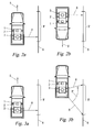
- the conveyor 1 is moved in a first direction of travel 5 and the scanning plane 8 of the laser scanner 3 is held in a first angular position in order to produce a first 3D image 13 (FIG. Fig. 4 ) of a selected area 9 'of the environment 9.
- the transport means 1 in a second direction of travel 5 '(here: opposite) along the same area 9' moves and the scanning plane 8 in a second angular position (here: turned by 180 °) held to a second 3D image 14 (FIG. Fig. 4 ) of the same environment area 9 '.
- One and the same object 15 is now identified in the two 3D images 13, 14, for example by pattern detection methods of a type known per se.
- the object is a flat region of a building front.
- the respective spatial position of the object 15 is determined in the 3D images 13, 14, u.zw.
- a surface is selected as the object 15, and the surface normals 16, 17 of the object 15 in the 3D images 13, 14 indicate its respective spatial position, see FIG Fig. 4 ,
- a relative offset of the laser scanner 3 relative to the reference system 2 e.g. a solid angle difference 18 between the axis 19 of the coordinate system 12 and the axis 20 of the coordinate system 7, is reflected in a spatial angle difference 21 of the spatial axes 16 and 17 of the object 15 in the 3D images 13, 14 down.
- This can be concluded from a comparison of the spatial positions of the object 15 in the 3D images 13, 14 on the relative position between the laser scanner 3 and the reference system 2.
- the second direction of travel 5 'of the first direction of travel 5 and the second angular position of the scanning plane 8 The first angular position is exactly opposite by 180 ° and the directions of travel 5, 5 'are parallel to a planar object 15 ( Fig. 2a, 2b). If, on the other hand, the directions of travel 5, 5 'and the angular positions of the scanning plane 8 deviate from this case, the spatial positions of the object determined in the 3D images 13, 14 need to be determined 15 only to be compensated for the respective direction of travel and angular position deviations in order to obtain exclusively the spatial angle difference 18 due to the angular offset of the laser scanner 3 relative to the reference system 2.
- the first and / or second scan passes the Fig. 2a and 2b also in each case in a direction obliquely to the surrounding area 9 'running direction 5, 5' and / or carried out with non-rectangular angular positions of the scanning plane 8.
- a planar object 15 could also be defined merely by three arbitrary, significant points 22, 23, 24 in the surroundings 9.
- the 3D images 13, 14 could be reduced in their spatial resolution, if desired, to those 2D profiles 10 which contain or surround these points, provided that a corresponding selection of the points and / or pre-adjustment of the scanning plane 8 to certain points in the environment 9 is possible.
- the Fig. 3a and 3b show a further process variant in which in the first step ( Fig. 3a ) the transport means 1 is moved in a first direction of travel 5 along the surrounding area 9 'in order to produce the first 3D image 13, while in the second step ( Fig. 3b ) the conveyor 1 is stopped and the scanning plane 8 of the laser scanner 3 is brought into different angular positions, see arrow 5 ", to produce from the same surrounding area 9 'the second 3D image 14.
- the second 3D image 14 is compensated by the pivot angle (arrow 5 "), ie equalized.
- the process step of Fig. 3b can also before the step of Fig. 3a be executed.
- the direction of travel 5 in the step of Fig. 3a , the stop position of the conveyor 1 in the step of Fig. 3b and / or the angular positions of the scan planes 8 may also be selected differently than shown, as already discussed.
- Fig. 5 shows such an alternative embodiment, which carries three 3D laser scanners 3, 3 ', 3 "with pivotable scanning planes 8, 25, 26 in vertical directions to both sides of the conveyor 1 and two 2D laser scanners 27, 28, one of which Rear of the means of transport 1 a vertical fan-fold 29 and the other a obliquely forward up or down directed laser fan 30 radiates.
- Each of the other laser scanners 3 ', 3 ", 27 and 28 has - analogously to the laser scanner 3 in FIG Fig. 1 with its coordinate system 12 - via its own (not shown here) coordinate system, which may be misaligned with respect to the laser scanner 3 and / or the reference system 2.
- the described methods can be used in cascade: As in FIG Fig. 6
- a further 3D image 31 of the surrounding area 9 ' is created for each further laser scanner, eg by moving it down in accordance with FIGS Fig. 2a and 2b or swinging in accordance with the Fig. 3a and 3b , and in the object 15 is detected again.
- the relative position of each further laser scanner 3 ', 3 ", 27 and 28 relative to the laser scanner 3 and / or the reference system 2 can now be determined.
Landscapes
- Physics & Mathematics (AREA)
- Engineering & Computer Science (AREA)
- Electromagnetism (AREA)
- General Physics & Mathematics (AREA)
- Radar, Positioning & Navigation (AREA)
- Remote Sensing (AREA)
- Computer Networks & Wireless Communication (AREA)
- Length Measuring Devices By Optical Means (AREA)
Abstract
Description
Die vorliegende Erfindung betrifft ein Verfahren zum Bestimmen der Relativlage eines Laserscanners, der in einer Abtastebene ein 2D-Profil seiner Umgebung erfaßt und von einem Beförderungsmittel in einer abtastebenen-fremden Fahrtrichtung mitgeführt wird, um ein 3D-Abbild der Umgebung zu erstellen, relativ zu einem Referenzsystem des Beförderungsmittels.The present invention relates to a method for determining the relative position of a laser scanner, which detects a 2D profile of its surroundings in a scanning plane and is carried by a conveyor in a scanning plane-foreign direction to create a 3D image of the environment, relative to a Reference system of the means of transport.
Laserscanner dieser Art sind beispielsweise aus der
Für die Meßgenauigkeit des Mobile Scanning ist es von entscheidender Bedeutung, daß die Bewegungsbahn und -orientierung des Fahrzeugs, hier unter dem Begriff "Trajektorie" zusammengefaßt, sowie die Lage des Laserscanners am Fahrzeug genau bekannt sind. Bereits Winkelabweichungen von wenigen Milligrad können über die von den Abtaststrahlen zurückzulegenden langen Wege zu signifikanten Vermessungsfehlern führen.For the measurement accuracy of the mobile scanning, it is of crucial importance that the trajectory and orientation of the vehicle, summarized here under the term "trajectory", as well as the location of the laser scanner on the vehicle are well known. Already angular deviations of a few milligrams can lead to significant surveying errors over the long paths to be traveled by the scanning beams.
Zur Bestimmung der Trajektorie wird üblicherweise ein am Fahrzeug montiertes Trägheitsmeßsystem ("inertial measurement unit", IMU) in Verbindung mit einem Satellitennavigationssystem ("global navigation satellite system", GNSS) als Referenzsystem für die Bewegung herangezogen. Die Relativlage des Laserscanners gegenüber dem Referenzsystem muß bislang mittels Kalibriermessungen in einer kontrollierten Meßumgebung mit definierten Meßstrecken und -punkten einjustiert werden. Bei der Erstmontage und jeder neuerlichen Montage des Laserscanners am Fahrzeug, z.B. zu Reparaturzwecken oder wenn verschiedene Anlagen modular gewechselt werden sollen, ist jedesmal eine Kalibrierung in der Meßumgebung erforderlich, was überaus zeit- und kostenintensiv ist.To determine the trajectory, a vehicle-mounted inertial measurement unit (IMU) in conjunction with a global navigation satellite system (GNSS) is usually used as a reference system for the movement. The relative position of the laser scanner relative to the reference system must hitherto be adjusted by means of calibration measurements in a controlled measuring environment with defined measuring distances and points. During the initial installation and every new installation of the laser scanner on the Vehicle, eg for repair purposes or if different systems are to be changed modularly, a calibration in the measurement environment is required each time, which is extremely time and cost intensive.
Die Erfindung setzt sich zum Ziel, die Nachteile des bekannten Stand der Technik zu überwinden und ein Verfahren zum Bestimmen der Relativlage eines Laserscanners gegenüber einem Bewegungsreferenzsystem zu schaffen, welches einfach, rasch und ohne besondere Hilfsmittel durchgeführt werden kann. Dieses Ziel wird mit einem Verfahren der einleitend genannten Art erreicht, das die folgenden Schritte aufweist:
- Verwenden eines Laserscanners, dessen Abtastebene in zumindest zwei Winkelstellungen vorwählbar ist,
- Erstellen zweier 3D-Abbilder eines ausgewählten Umgebungsbereichs unter zwei verschiedenen Winkelstellungen des Laserscanners, und
- Bestimmen der Relativlage aus einem Vergleich der Raumlage eines Objekts im ersten 3D-Abbild mit der Raumlage desselben Objekts im zweiten 3D-Abbild.
- Using a laser scanner whose scanning plane can be preselected in at least two angular positions,
- Create two 3D images of a selected environmental area under two different laser scanner angles, and
- Determining the relative position from a comparison of the spatial position of an object in the first 3D image with the spatial position of the same object in the second 3D image.
Das Verfahren der Erfindung beruht auf der Erkenntnis, daß sich ein Winkelversatz in der Relativlage des Laserscanners gegenüber dem Bewegungsreferenzsystem bei zwei Scandurchgängen mit verschiedenen Winkelstellungen der Abtastebene in einem Winkelversatz der beiden 3D-Abbilder niederschlägt, welcher gemessen werden kann und einen direkten Rückschluß auf die Relativlage zuläßt. Das Verfahren der Erfindung erfordert dazu keine besondere Referenz- oder Meßumgebung, sondern kann direkt vor Ort ohne zusätzliche Hilfsmittel durchgeführt werden. Dies ermöglicht sowohl eine rasche Erstmontage als auch einen raschen Austausch des Laserscanners zu Reparaturzwecken, für eine vorübergehende anderweitige Verwendung des Laserscanners fernab vom Beförderungsmittel oder für einen modularen Wechsel verschiedener Laserscanner an einem bestimmten Beförderungsmittel ohne Abstriche in der Abbildungsgenauigkeit.The method of the invention is based on the finding that an angular offset in the relative position of the laser scanner relative to the motion reference system in two scan passes with different angular positions of the scanning reflected in an angular offset of the two 3D images, which can be measured and a direct inference to the relative position allows. The method of the invention requires no special reference or measuring environment, but can be carried out directly on site without additional aids. This allows both a quick initial assembly and a quick replacement of the laser scanner for repair purposes, for a temporary other use of the laser scanner far away from the conveyor or for a modular change of different laser scanners on a particular means of conveyance without compromising the accuracy of imaging.
Die Veränderung der Abtastebene des Laserscanners kann auf verschiedene Arten erreicht werden. Beispielsweise kann der Laserscanner zwei elektronisch oder optisch umschaltbare Strahlfächer ausstrahlen, oder auch nur einen einzigen Strahlfächer, der mit Hilfe einer mechanischen Schwenklagerung des Laserscanners in unterschiedliche Winkelstellungen bringbar ist. Besonders vorteilhaft ist es, wenn als Laserscanner zumindest ein steuerbarer 3D-Laserscanner eingesetzt wird. Ein 3D-Laserscanner erzeugt einerseits einen Strahlfächer in einer Abtastebene zur Erfassung eines 2D-Profils und rotiert anderseits um eine zusätzliche Achse, um über den gewählten Rotationswinkel aus einer Vielzahl von 2D-Profilen ein 3D-Abbild der Umgebung zu erzeugen. Die Verwendung eines solchen 3D-Laserscanners hat den Vorteil, daß die jeweilige Winkelstellung der Abtastebene aufgrund der geräteintern bereits vorhandenen Mechatronik zur Winkelsteuerung besonders genau bekannt ist und die Rotationsachse genau mit der Scannerachse zusammenfällt.The change in the scanning plane of the laser scanner can be achieved in various ways. For example, the laser scanner can emit two electronically or optically switchable jet fans, or even a single beam fan, which can be brought into different angular positions by means of a mechanical pivotal mounting of the laser scanner. It is particularly advantageous if at least one controllable 3D laser scanner is used as the laser scanner. On the one hand, a 3D laser scanner generates a beam fan in a scanning plane for detecting a 2D profile and, on the other hand, rotates about an additional axis in order to generate a 3D image of the environment via the selected rotation angle from a large number of 2D profiles. The use of such a 3D laser scanner has the advantage that the respective angular position of the scanning plane is particularly well known due to the device's already existing mechatronics for angle control and the axis of rotation coincides exactly with the scanner axis.
Gemäß einem weiteren bevorzugten Merkmal der Erfindung können aus der so ermittelten Relativlage des Laserscanners die Relativlagen allfälliger weiterer vom Beförderungsmittel mitgeführter Laserscanner relativ zum genannten Laserscanner und/oder zum Referenzsystem ermittelt werden, u.zw. mittels der Schritte
Erstellen eines weiteren 3D-Abbilds desselben Umgebungsbereichs mittels des weiteren Laserscanners, undAccording to a further preferred feature of the invention can be determined relative to the said laser scanner and / or to the reference system from the relative position of any further carried by the means of transport laser scanner from the thus determined relative position of the laser scanner, u.zw. by means of the steps
Create another 3D image of the same environment using the other laser scanner, and
Bestimmen der genannten Relativlage aus einem Vergleich der Raumlage des Objekts im weiteren 3D-Abbild mit zumindest einer der zuvor ermittelten Raumlagen.Determining said relative position from a comparison of the spatial position of the object in the further 3D image with at least one of the previously determined spatial positions.
In einer ersten bevorzugten Ausführungsform der Erfindung werden die zwei genannten 3D-Abbilder mit Hilfe der folgenden Schritte erstellt:
- Erstellen des ersten 3D-Abbilds des Umgebungsbereichs durch Bewegen des Beförderungsmittels in einer ersten Fahrtrichtung und Halten der Abtastebene in einer ersten Winkelstellung, und
- Erstellen des zweiten 3D-Abbilds etwa desselben Umgebungsbereichs durch Bewegen des Beförderungsmittels in einer zweiten Fahrtrichtung und Halten der Abtastebene in einer zweiten Winkelstellung.
- Creating the first 3D image of the surrounding area by moving the conveyance in a first direction of travel and maintaining the scanning plane in a first angular position, and
- Creating the second 3D image of approximately the same surrounding area by moving the conveyance in a second direction of travel and maintaining the scanning plane in a second angular position.
Besonders vorteilhaft ist es, wenn die erste Fahrtrichtung der zweiten Fahrtrichtung und die erste Winkelstellung der zweiten Winkelstellung entgegengesetzt ist. Beim Vergleichen der Raumlagen in den 3D-Abbildern brauchen dadurch weniger fahrtrichtungs- und winkelstellungsbedingte Verzerrungen kompensiert zu werden.It when the first direction of travel of the second direction and the first angular position of the second angular position is opposite is particularly advantageous. When comparing the spatial positions in the 3D images thus less direction of travel and angular position related distortions need to be compensated.
In einer zweiten bevorzugten Ausführungsform der Erfindung werden die beiden 3D-Abbilder mit Hilfe der folgenden Schritte erstellt:
- Erstellen des ersten 3D-Abbilds des Umgebungsbereichs durch Halten der Abtastebene und Bewegen des Beförderungsmittels, und voraus- oder nachgehendes
- Erstellen des zweiten 3D-Abbilds etwa desselben Umgebungsbereichs durch Halten des Beförderungsmittels und aufeinanderfolgendes Versetzen der Abtastebene in zumindest zwei verschiedene Winkelstellungen.
- Creating the first 3D image of the surrounding area by holding the scanning plane and moving the means of transport, and before or after
- Creating the second 3D image of approximately the same surrounding area by holding the conveying means and successively displacing the scanning plane in at least two different angular positions.
Bevorzugt wird dabei die Abtastebene in zahlreiche aufeinanderfolgende Winkelstellungen verschwenkt, wodurch bei stillstehendem Beförderungsmittel eine höhere räumliche Auflösung erreicht werden kann, welche die Objektidentifizierung in den 3D-Abbildern erleichtert.Preferably, the scanning plane is pivoted into numerous successive angular positions, whereby a higher spatial resolution can be achieved when the conveyor is stationary, which facilitates the object identification in the 3D images.
Eine implementierungstechnisch besonders günstige Ausführungsform des Verfahrens zeichnet sich dadurch aus, daß in den genannten Vergleichen die Relativlage aus der Raumwinkeldifferenz der Raumlagen einer ausgewählten Raumachse des Objekts, bereinigt um die genannten Fahrtrichtungs- und Winkelstellungsänderungen zwischen den verschiedenen 3D-Abbildern, bestimmt wird.An implementation technology particularly favorable embodiment of the method is characterized in that in the mentioned comparisons, the relative position of the solid angle difference of the spatial positions of a selected spatial axis of the object, adjusted for the aforementioned direction of travel and angular position changes between the various 3D images, is determined.
Bevorzugt wird als Objekt eine in der Umgebung detektierte Fläche und als genannte Raumachse deren Flächennormale ausgewählt, wodurch Implementierungen mit besonders geringen Rechenzeiten erreicht werden können.Preferably, an area detected in the environment is selected as the object, and its surface normal as said spatial axis, whereby implementations with particularly short computation times can be achieved.
In allen Varianten der Verfahren ist es besonders günstig, wenn der Laserscanner über eine Schnellbefestigung austauschbar am Beförderungsmittel montiert wird, was einen raschen Wechsel des Laserscanners im Feld ermöglicht.In all variants of the method, it is particularly advantageous if the laser scanner is mounted interchangeably on the means of transport via a quick attachment, which allows a rapid change of the laser scanner in the field.
Die Erfindung wird nachstehend anhand von in den beigeschlossenen Zeichnungen dargestellten Ausführungsbeispielen näher erläutert. In den Zeichnungen zeigen:
-
Fig. 1 ein Beförderungsmittel mit einem Laserscanner zur 3D-Erfassung eines Umgebungsbereichs in der Perspektivansicht; - die
Fig. 2a und 2b eine erste Ausführungsform des Verfahrens der Erfindung in Form von Draufsichten auf ein Beförderungsmittel während des Erstellens zweier 3D-Abbilder; - die
Fig. 3a und 3b eine zweite Ausführungsform des Verfahrens der Erfindung in Form von Draufsichten auf ein Beförderungsmittel während des Erstellens zweier 3D-Abbilder; -
Fig. 4 den Schritt des Bestimmens der Relativlage des Laserscanners aus dem Vergleich der Raumlagen eines Objekts in den 3D-Abbildern; -
Fig. 5 eine Draufsicht auf eine Ausführungsform mit mehreren Laserscannern zur Verwendung in dem Verfahren der Erfindung; und -
Fig. 6 den Schritt des Bestimmens der Relativlage eines weiteren vom Beförderungsmittel mitgeführten Laserscanners gegenüber dem Referenzsystem und/oder anderen Laserscannern.
-
Fig. 1 a conveyor with a laser scanner for 3D detection of a surrounding area in the perspective view; - the
Fig. 2a and 2b a first embodiment of the method of the invention in the form of plan views of a conveyor during the creation of two 3D images; - the
Fig. 3a and 3b a second embodiment of the method of the invention in the form of plan views of a conveyor during the creation of two 3D images; -
Fig. 4 the step of determining the relative position of the laser scanner from the comparison of the spatial positions of an object in the 3D images; -
Fig. 5 a plan view of an embodiment with multiple laser scanners for use in the method of the invention; and -
Fig. 6 the step of determining the relative position of another carried by the means of transporting laser scanner relative to the reference system and / or other laser scanners.
Anstelle des gezeigten Geländewagens mit Dachträger kann das Beförderungsmittel 1 auch jedes beliebige andere Land-, Luft- oder Wasserfahrzeug sein, sowohl motor- als auch muskelkraftbetrieben, z.B. ein LKW, ein Schienenfahrzeug, ein Boot, eine Lore, eine Laufkatze oder im einfachsten Fall auch nur eine Trage.Instead of the illustrated roof-carrier SUV, the means of
Der Laserscanner 3 sendet in einer Abtastebene 8 einen Laserstrahlfächer auf eine Umgebung 9 aus, um aus der Reflektion des Laserstrahlfächers ein 2D-Profil 10 der Umgebung 9 zu erfassen. Durch Bewegen des Beförderungsmittels 1 in einer abtastebenen-fremden Fahrtrichtung 5 wird somit aus mehreren aufeinanderfolgenden 2D-Profilen 10 ein 3D-Abbild der Umgebung 9 erstellt und beispielsweise in einem Speicher des Laserscanners 3 gespeichert. Wie dem Fachmann bekannt, wird dabei - oder auch erst in einer späteren Offline-Auswertung der Scanner-Rohdaten - die vom Referenzsystem 2 ermittelte Trajektorie 4 des Beförderungsmittels 1 berücksichtigt, um die im Referenzkoordinatensystem 7 erfaßten 2D-Profile 10, um die Bewegungen bereinigt, als korrektes 3D-Abbild der Umgebung 9 im Weltkoordinatensystem 6 aufzubauen.The
Der Laserscanner 3 ist in einem Gehäuse gelagert und mittels einer daran angreifenden Schnellbefestigung 11, z.B. in Form einer arretierbaren Einschubhalterung, modular austauschbar am Beförderungsmittel 1 montiert. Die Relativlage des Laserscanners 3 gegenüber dem Referenzsystem 2 unterliegt somit Gehäuselagerungs- und Montagetoleranzen, die vorweg nicht bekannt sind; der Laserscanner 3 hat damit ein eigenes Koordinatensystem 12. Zum korrekten Aufbau des 3D-Abbilds der Umgebung 9 im Weltkoordinatensystem 6 ist folglich auch die Kenntnis der Relativlage des Laserscanners 3 gegenüber dem Referenzsystem 2, d.h. die Lage des Koordinatensystems 12 gegenüber dem Koordinatensystem 7, erforderlich, und diese wird nun wie folgt bestimmt.The
Wie in
In den beiden 3D-Abbildern 13, 14 wird nun jeweils ein und dasselbe Objekt 15 identifiziert, beispielsweise durch Musterdetektionsverfahren an sich bekannter Art. Im gezeigten Beispiel ist das Objekt ein flacher Bereich einer Gebäudefront.One and the
Anschließend wird die jeweilige Raumlage des Objekts 15 in den 3D-Abbildern 13, 14 ermittelt, u.zw. bevorzugt anhand einer ausgewählten, z.B. leicht identifizierbaren Raumachse des Objekts 15. Bevorzugt wird als Objekt 15 eine Fläche ausgewählt, und die Flächennormalen 16, 17 des Objekts 15 in den 3D-Abbildern 13, 14 geben seine jeweilige Raumlage an, siehe
Ein Relativversatz des Laserscanners 3 gegenüber dem Referenzsystem 2, z.B. eine Raumwinkeldifferenz 18 zwischen der Achse 19 des Koordinatensystems 12 und der Achse 20 des Koordinatensystems 7, schlägt sich in einer Raumwinkeldifferenz 21 der Raumachsen 16 und 17 des Objekts 15 in den 3D-Abbildern 13, 14 nieder. Damit kann aus einem Vergleich der Raumlagen des Objekts 15 in den 3D-Abbildern 13, 14 auf die Relativlage zwischen dem Laserscanner 3 und dem Referenzsystem 2 geschlossen werden.A relative offset of the
Wenn beispielsweise die zweite Fahrtrichtung 5' der ersten Fahrtrichtung 5 und die zweite Winkelstellung der Abtastebene 8 der ersten Winkelstellung genau um 180° entgegengesetzt ist und die Fahrtrichtungen 5, 5' parallel zu einem flächenhaften Objekt 15 liegen (
So könnten beispielsweise in einer alternativen Ausführungsform des Verfahrens der erste und/oder der zweite Scandurchgang der
Ein flächenhaftes Objekt 15 könnte im einfachsten Fall auch bloß durch drei beliebige, signifikante Punkte 22, 23, 24 in der Umgebung 9 definiert werden. Dadurch könnten die 3D-Abbilder 13, 14, falls gewünscht, in ihrer Raumauflösung auf solche 2D-Profile 10 reduziert werden, welche diese Punkte enthalten oder umgeben, soferne eine entsprechende Auswahl der Punkte und/oder Vorjustierung der Abtastebene 8 auf bestimmte Punkte der Umgebung 9 möglich ist.In the simplest case, a
Die
Der Verfahrensschritt von
Auf Grundlage der geschilderten Bestimmung der Relativlage des Laserscanners 3 gegenüber dem Referenzsystem 2 können anschließend die Relativlagen allfälliger weiterer vom Beförderungsmittel 1 mitgeführter Laserscanner ermittelt werden.
Jeder der weiteren Laserscanner 3', 3", 27 und 28 verfügt jeweils - analog dem Laserscanner 3 in
Zur Ermittlung der jeweiligen Relativlage der weiteren Laserscanners 3', 3", 27, 28 gegenüber dem Laserscanner 3 bzw. dem Referenzsystem 2 können die geschilderten Verfahren kaskadiert angewandt werden: Wie in
Die Erfindung ist nicht auf die dargestellten Ausführungsformen beschränkt, sondern umfaßt alle Varianten und Modifikationen, die in den Rahmen der angeschlossenen Ansprüche fallen.The invention is not limited to the illustrated embodiments, but includes all variants and modifications that fall within the scope of the appended claims.
Claims (10)
Erstellen eines weiteren 3D-Abbilds (31) desselben Umgebungsbereichs (9') mittels des weiteren Laserscanners (3', 3", 27, 28), und
Bestimmen der genannten Relativlage aus einem Vergleich der Raumlage (32) des Objekts (15) im weiteren 3D-Abbild (31) mit zumindest einer der zuvor ermittelten Raumlagen (16, 17).Method according to Claim 1 or 2 for determining the relative position of at least one further laser scanner (3 ', 3 ", 27, 28) carried by the conveying means (1) relative to said laser scanner (3) and / or reference system (2), characterized by steps
Creating a further 3D image (31) of the same surrounding area (9 ') by means of the further laser scanner (3', 3 ", 27, 28), and
Determining said relative position from a comparison of the spatial position (32) of the object (15) in the further 3D image (31) with at least one of the previously determined spatial positions (16, 17).
Erstellen des ersten 3D-Abbilds (13) des Umgebungsbereichs (9') durch Bewegen des Beförderungsmittels (1) in einer ersten Fahrtrichtung (5) und Halten der Abtastebene (8) in einer ersten Winkelstellung, und
Erstellen des zweiten 3D-Abbilds (14) etwa desselben Umgebungsbereichs (9') durch Bewegen des Beförderungsmittels (1) in einer zweiten Fahrtrichtung (5') und Halten der Abtastebene (8) in einer zweiten Winkelstellung.Method according to one of claims 1 to 3, characterized by the steps
Creating the first 3D image (13) of the surrounding area (9 ') by moving the conveyance (1) in a first one Driving direction (5) and holding the scanning plane (8) in a first angular position, and
Creating the second 3D image (14) of approximately the same surrounding area (9 ') by moving the conveying means (1) in a second traveling direction (5') and holding the scanning plane (8) in a second angular position.
Erstellen des ersten 3D-Abbilds (13) des Umgebungsbereichs (9') durch Halten der Abtastebene (8) und Bewegen des Beförderungsmittels (1), und voraus- oder nachgehendes
Erstellen des zweiten 3D-Abbilds (14) etwa desselben Umgebungsbereichs (9') durch Halten des Beförderungsmittels (1) und aufeinanderfolgendes Versetzen der Abtastebene (8) in zumindest zwei verschiedene Winkelstellungen.Method according to one of claims 1 to 3, characterized by the steps
Creating the first 3D image (13) of the surrounding area (9 ') by holding the scanning plane (8) and moving the means of transport (1), and before or after
Creating the second 3D image (14) of approximately the same surrounding area (9 ') by holding the conveying means (1) and successively displacing the scanning plane (8) into at least two different angular positions.
Applications Claiming Priority (1)
| Application Number | Priority Date | Filing Date | Title |
|---|---|---|---|
| AT0184608A AT507618B1 (en) | 2008-11-26 | 2008-11-26 | METHOD FOR DETERMINING THE RELATIVE POSITION OF A LASER SCANNER TO A REFERENCE SYSTEM |
Publications (3)
| Publication Number | Publication Date |
|---|---|
| EP2199828A2 true EP2199828A2 (en) | 2010-06-23 |
| EP2199828A3 EP2199828A3 (en) | 2010-12-01 |
| EP2199828B1 EP2199828B1 (en) | 2011-12-28 |
Family
ID=41718468
Family Applications (1)
| Application Number | Title | Priority Date | Filing Date |
|---|---|---|---|
| EP09450183A Active EP2199828B1 (en) | 2008-11-26 | 2009-09-24 | Method for determining the position of a laser scanner relative to a reference system |
Country Status (2)
| Country | Link |
|---|---|
| EP (1) | EP2199828B1 (en) |
| AT (2) | AT507618B1 (en) |
Cited By (10)
| Publication number | Priority date | Publication date | Assignee | Title |
|---|---|---|---|---|
| WO2012012819A1 (en) * | 2010-07-26 | 2012-02-02 | Commonwealth Scientific And Industrial Research Organisation | Three dimensional scanning beam system and method |
| JP2015212942A (en) * | 2014-04-25 | 2015-11-26 | グーグル インコーポレイテッド | Methods and systems for object detection using laser point clouds |
| JP2016001182A (en) * | 2015-07-21 | 2016-01-07 | コモンウェルス サイエンティフィック アンド インダストリアル リサーチ オーガナイゼーション | Three-dimensional scanning beam system and method |
| DE102016225595A1 (en) * | 2016-12-20 | 2018-06-21 | Siemens Aktiengesellschaft | Method and arrangement for calibrating at least one sensor of a rail vehicle |
| DE102018208080B3 (en) | 2018-05-23 | 2019-09-19 | Kuka Deutschland Gmbh | Method and system for locating an object in a robot environment |
| DE102018108141A1 (en) | 2018-04-06 | 2019-10-10 | Navvis Gmbh | Mobile device and method for detecting an object space |
| EP3739291A1 (en) | 2019-05-17 | 2020-11-18 | Hexagon Technology Center GmbH | Fully automatic position and orientation detection method for terrestrial laser scanner |
| CN113552580A (en) * | 2020-04-17 | 2021-10-26 | 上海禾赛科技有限公司 | Laser radar and method for detecting target object by using same |
| US11604065B2 (en) | 2019-05-17 | 2023-03-14 | Hexagon Technology Center Gmbh | Fully automatic position and alignment determination method for a terrestrial laser scanner and method for ascertaining the suitability of a position for a deployment for surveying |
| DE102022102322A1 (en) | 2022-02-01 | 2023-08-03 | Bayerische Motoren Werke Aktiengesellschaft | METHOD OF CORRECTING DESIGN-RELATED IMAGING DEFECT OF A LIDAR SENSOR, COMPUTING DEVICE, LIDAR SENSOR SYSTEM, COMPUTER PROGRAM, AND COMPUTER READABLE (STORAGE) MEDIUM |
Citations (1)
| Publication number | Priority date | Publication date | Assignee | Title |
|---|---|---|---|---|
| GB2434269A (en) | 2006-01-17 | 2007-07-18 | 3D Laser Mapping Ltd | Laser measuring apparatus and position determining device for surveying and route clearance measurement |
Family Cites Families (6)
| Publication number | Priority date | Publication date | Assignee | Title |
|---|---|---|---|---|
| GB2372656A (en) * | 2001-02-23 | 2002-08-28 | Ind Control Systems Ltd | Optical position determination |
| DE102004033114A1 (en) * | 2004-07-08 | 2006-01-26 | Ibeo Automobile Sensor Gmbh | Method for calibrating a distance image sensor |
| EP2078286A1 (en) * | 2006-10-30 | 2009-07-15 | Tele Atlas B.V. | Method and apparatus for detecting objects from terrestrial based mobile mapping data |
| CN101563625A (en) * | 2006-11-06 | 2009-10-21 | 电子地图有限公司 | Arrangement for and method of two dimensional and three dimensional precision location and orientation determination |
| GB2443856A (en) * | 2006-11-18 | 2008-05-21 | Stephen George Nunney | Distance and position measuring system for producing a model of a structure or topography |
| CA2606267A1 (en) * | 2007-10-11 | 2009-04-11 | Hydro-Quebec | System and method for three-dimensional mapping of a structural surface |
-
2008
- 2008-11-26 AT AT0184608A patent/AT507618B1/en active
-
2009
- 2009-09-24 EP EP09450183A patent/EP2199828B1/en active Active
- 2009-09-24 AT AT09450183T patent/ATE539362T1/en active
Patent Citations (1)
| Publication number | Priority date | Publication date | Assignee | Title |
|---|---|---|---|---|
| GB2434269A (en) | 2006-01-17 | 2007-07-18 | 3D Laser Mapping Ltd | Laser measuring apparatus and position determining device for surveying and route clearance measurement |
Cited By (17)
| Publication number | Priority date | Publication date | Assignee | Title |
|---|---|---|---|---|
| CN103180794A (en) * | 2010-07-26 | 2013-06-26 | 联邦科学和工业研究组织 | Three dimensional scanning beam system and method |
| US9146315B2 (en) | 2010-07-26 | 2015-09-29 | Commonwealth Scientific And Industrial Research Organisation | Three dimensional scanning beam system and method |
| CN103180794B (en) * | 2010-07-26 | 2017-02-15 | 联邦科学和工业研究组织 | Three dimensional scanning beam system and method |
| WO2012012819A1 (en) * | 2010-07-26 | 2012-02-02 | Commonwealth Scientific And Industrial Research Organisation | Three dimensional scanning beam system and method |
| JP2015212942A (en) * | 2014-04-25 | 2015-11-26 | グーグル インコーポレイテッド | Methods and systems for object detection using laser point clouds |
| JP2017152049A (en) * | 2014-04-25 | 2017-08-31 | グーグル インコーポレイテッド | Methods and systems for object detection using laser point clouds |
| JP2016001182A (en) * | 2015-07-21 | 2016-01-07 | コモンウェルス サイエンティフィック アンド インダストリアル リサーチ オーガナイゼーション | Three-dimensional scanning beam system and method |
| DE102016225595A1 (en) * | 2016-12-20 | 2018-06-21 | Siemens Aktiengesellschaft | Method and arrangement for calibrating at least one sensor of a rail vehicle |
| WO2019193207A1 (en) | 2018-04-06 | 2019-10-10 | Navvis Gmbh | Mobile apparatus and method for detecting an object space |
| DE102018108141A1 (en) | 2018-04-06 | 2019-10-10 | Navvis Gmbh | Mobile device and method for detecting an object space |
| DE102018208080B3 (en) | 2018-05-23 | 2019-09-19 | Kuka Deutschland Gmbh | Method and system for locating an object in a robot environment |
| EP3739291A1 (en) | 2019-05-17 | 2020-11-18 | Hexagon Technology Center GmbH | Fully automatic position and orientation detection method for terrestrial laser scanner |
| US11604065B2 (en) | 2019-05-17 | 2023-03-14 | Hexagon Technology Center Gmbh | Fully automatic position and alignment determination method for a terrestrial laser scanner and method for ascertaining the suitability of a position for a deployment for surveying |
| US11740086B2 (en) | 2019-05-17 | 2023-08-29 | Hexagon Technology Center Gmbh | Method for ascertaining the suitability of a position for a deployment for surveying |
| CN113552580A (en) * | 2020-04-17 | 2021-10-26 | 上海禾赛科技有限公司 | Laser radar and method for detecting target object by using same |
| DE102022102322A1 (en) | 2022-02-01 | 2023-08-03 | Bayerische Motoren Werke Aktiengesellschaft | METHOD OF CORRECTING DESIGN-RELATED IMAGING DEFECT OF A LIDAR SENSOR, COMPUTING DEVICE, LIDAR SENSOR SYSTEM, COMPUTER PROGRAM, AND COMPUTER READABLE (STORAGE) MEDIUM |
| WO2023147961A1 (en) | 2022-02-01 | 2023-08-10 | Bayerische Motoren Werke Aktiengesellschaft | Method for correcting a design-related aberration of a lidar sensor, computing device, lidar sensor system, computer program, and computer-readable (storage) medium |
Also Published As
| Publication number | Publication date |
|---|---|
| EP2199828B1 (en) | 2011-12-28 |
| AT507618A1 (en) | 2010-06-15 |
| ATE539362T1 (en) | 2012-01-15 |
| AT507618B1 (en) | 2012-01-15 |
| EP2199828A3 (en) | 2010-12-01 |
Similar Documents
| Publication | Publication Date | Title |
|---|---|---|
| EP2199828B1 (en) | Method for determining the position of a laser scanner relative to a reference system | |
| DE102004010197B4 (en) | Method for checking the function of a position-finding or environment detection device of a vehicle or for controlling a digital map | |
| AT509103B1 (en) | METHOD FOR SUPPORTING THE MEASURING ACCURACY OF GPS / IMU SYSTEMS | |
| EP2800982B1 (en) | Method and device for measuring the speed of a vehicle independently of the wheels | |
| DE102005012107B4 (en) | Measuring system and method for geodetic surveying of objects | |
| EP1673589B1 (en) | Method and device for determining the actual position of a geodetic instrument | |
| WO2016120044A1 (en) | Measurement of a dimension on a surface | |
| WO2005090907A1 (en) | Method for locating defective points and marking system | |
| DE102017109445A1 (en) | Calibration of a vehicle camera device in the vehicle longitudinal direction or vehicle transverse direction | |
| DE102017128194A1 (en) | Accurate self-locating using a synthetic aperture automotive radar | |
| EP3367133A1 (en) | Method for calibrating a gnss antenna of a vehicle | |
| DE102008019373A1 (en) | Method for calibrating a measuring device of a crane comprises acquiring the surface of the container using sensors, determining the orientation of the surface of the container in reference systems and equilibrating the reference systems | |
| EP2193334A1 (en) | Sensor unit and method for calibration thereof | |
| DE102020007772A1 (en) | Procedure for in-service calibration of a lidar and vehicle | |
| DE102018210340A1 (en) | Method and system for determining a relative pose between a target object and a vehicle | |
| DE102018108141A1 (en) | Mobile device and method for detecting an object space | |
| DE102021204363A1 (en) | Method for calibrating a sensor using a means of transportation | |
| DE102008000837A1 (en) | Chassis measuring system and method for determining the positional parameters of measuring heads of a chassis measuring system | |
| DE4416557A1 (en) | Method and device for supporting the inertial navigation of a missile autonomously controlling a distant target | |
| EP1387996B1 (en) | Method for measuring and/or machining a workpiece | |
| DE102019206918B3 (en) | Position determination method and position determination device | |
| DE102012012002A1 (en) | Environment acquisition method for mobile generation of three-dimensional-scan of environment around distance of motor car, involves determining trajectory of motor car from specifications that are determined by sensors during test run | |
| DE102018213994A1 (en) | Method and system for determining the movement of a motor vehicle | |
| DE10210472A1 (en) | Method for adjusting the alignment of a sensor unit and device for carrying out the method | |
| EP4211499A1 (en) | Mobile scanning arrangement and method for controlling a mobile scanning arrangement |
Legal Events
| Date | Code | Title | Description |
|---|---|---|---|
| PUAI | Public reference made under article 153(3) epc to a published international application that has entered the european phase |
Free format text: ORIGINAL CODE: 0009012 |
|
| AK | Designated contracting states |
Kind code of ref document: A2 Designated state(s): AT BE BG CH CY CZ DE DK EE ES FI FR GB GR HR HU IE IS IT LI LT LU LV MC MK MT NL NO PL PT RO SE SI SK SM TR |
|
| AX | Request for extension of the european patent |
Extension state: AL BA RS |
|
| PUAL | Search report despatched |
Free format text: ORIGINAL CODE: 0009013 |
|
| AK | Designated contracting states |
Kind code of ref document: A3 Designated state(s): AT BE BG CH CY CZ DE DK EE ES FI FR GB GR HR HU IE IS IT LI LT LU LV MC MK MT NL NO PL PT RO SE SI SK SM TR |
|
| AX | Request for extension of the european patent |
Extension state: AL BA RS |
|
| RIC1 | Information provided on ipc code assigned before grant |
Ipc: G01S 17/48 20060101ALI20101028BHEP Ipc: G01S 17/06 20060101ALI20101028BHEP Ipc: G01S 17/02 20060101ALI20101028BHEP Ipc: G01S 17/89 20060101AFI20100303BHEP Ipc: G01S 7/481 20060101ALI20101028BHEP Ipc: G01S 5/16 20060101ALI20101028BHEP |
|
| 17P | Request for examination filed |
Effective date: 20110111 |
|
| 17Q | First examination report despatched |
Effective date: 20110223 |
|
| RIC1 | Information provided on ipc code assigned before grant |
Ipc: G01S 17/48 20060101ALI20110601BHEP Ipc: G01S 7/481 20060101ALI20110601BHEP Ipc: G01S 5/16 20060101ALI20110601BHEP Ipc: G01S 17/02 20060101ALI20110601BHEP Ipc: G01S 17/89 20060101AFI20110601BHEP Ipc: G01S 17/06 20060101ALI20110601BHEP |
|
| GRAP | Despatch of communication of intention to grant a patent |
Free format text: ORIGINAL CODE: EPIDOSNIGR1 |
|
| GRAS | Grant fee paid |
Free format text: ORIGINAL CODE: EPIDOSNIGR3 |
|
| GRAA | (expected) grant |
Free format text: ORIGINAL CODE: 0009210 |
|
| AK | Designated contracting states |
Kind code of ref document: B1 Designated state(s): AT BE BG CH CY CZ DE DK EE ES FI FR GB GR HR HU IE IS IT LI LT LU LV MC MK MT NL NO PL PT RO SE SI SK SM TR |
|
| REG | Reference to a national code |
Ref country code: GB Ref legal event code: FG4D Free format text: NOT ENGLISH |
|
| REG | Reference to a national code |
Ref country code: CH Ref legal event code: EP |
|
| REG | Reference to a national code |
Ref country code: AT Ref legal event code: REF Ref document number: 539362 Country of ref document: AT Kind code of ref document: T Effective date: 20120115 |
|
| REG | Reference to a national code |
Ref country code: IE Ref legal event code: FG4D |
|
| REG | Reference to a national code |
Ref country code: CH Ref legal event code: NV Representative=s name: BUECHEL, VON REVY & PARTNER |
|
| REG | Reference to a national code |
Ref country code: DE Ref legal event code: R096 Ref document number: 502009002304 Country of ref document: DE Effective date: 20120308 |
|
| REG | Reference to a national code |
Ref country code: NL Ref legal event code: VDEP Effective date: 20111228 |
|
| PG25 | Lapsed in a contracting state [announced via postgrant information from national office to epo] |
Ref country code: NO Free format text: LAPSE BECAUSE OF FAILURE TO SUBMIT A TRANSLATION OF THE DESCRIPTION OR TO PAY THE FEE WITHIN THE PRESCRIBED TIME-LIMIT Effective date: 20120328 Ref country code: LT Free format text: LAPSE BECAUSE OF FAILURE TO SUBMIT A TRANSLATION OF THE DESCRIPTION OR TO PAY THE FEE WITHIN THE PRESCRIBED TIME-LIMIT Effective date: 20111228 |
|
| LTIE | Lt: invalidation of european patent or patent extension |
Effective date: 20111228 |
|
| PG25 | Lapsed in a contracting state [announced via postgrant information from national office to epo] |
Ref country code: GR Free format text: LAPSE BECAUSE OF FAILURE TO SUBMIT A TRANSLATION OF THE DESCRIPTION OR TO PAY THE FEE WITHIN THE PRESCRIBED TIME-LIMIT Effective date: 20120329 Ref country code: HR Free format text: LAPSE BECAUSE OF FAILURE TO SUBMIT A TRANSLATION OF THE DESCRIPTION OR TO PAY THE FEE WITHIN THE PRESCRIBED TIME-LIMIT Effective date: 20111228 Ref country code: SI Free format text: LAPSE BECAUSE OF FAILURE TO SUBMIT A TRANSLATION OF THE DESCRIPTION OR TO PAY THE FEE WITHIN THE PRESCRIBED TIME-LIMIT Effective date: 20111228 Ref country code: LV Free format text: LAPSE BECAUSE OF FAILURE TO SUBMIT A TRANSLATION OF THE DESCRIPTION OR TO PAY THE FEE WITHIN THE PRESCRIBED TIME-LIMIT Effective date: 20111228 Ref country code: SE Free format text: LAPSE BECAUSE OF FAILURE TO SUBMIT A TRANSLATION OF THE DESCRIPTION OR TO PAY THE FEE WITHIN THE PRESCRIBED TIME-LIMIT Effective date: 20111228 |
|
| PG25 | Lapsed in a contracting state [announced via postgrant information from national office to epo] |
Ref country code: CY Free format text: LAPSE BECAUSE OF FAILURE TO SUBMIT A TRANSLATION OF THE DESCRIPTION OR TO PAY THE FEE WITHIN THE PRESCRIBED TIME-LIMIT Effective date: 20111228 |
|
| REG | Reference to a national code |
Ref country code: IE Ref legal event code: FD4D |
|
| PG25 | Lapsed in a contracting state [announced via postgrant information from national office to epo] |
Ref country code: NL Free format text: LAPSE BECAUSE OF FAILURE TO SUBMIT A TRANSLATION OF THE DESCRIPTION OR TO PAY THE FEE WITHIN THE PRESCRIBED TIME-LIMIT Effective date: 20111228 Ref country code: SK Free format text: LAPSE BECAUSE OF FAILURE TO SUBMIT A TRANSLATION OF THE DESCRIPTION OR TO PAY THE FEE WITHIN THE PRESCRIBED TIME-LIMIT Effective date: 20111228 Ref country code: EE Free format text: LAPSE BECAUSE OF FAILURE TO SUBMIT A TRANSLATION OF THE DESCRIPTION OR TO PAY THE FEE WITHIN THE PRESCRIBED TIME-LIMIT Effective date: 20111228 Ref country code: BG Free format text: LAPSE BECAUSE OF FAILURE TO SUBMIT A TRANSLATION OF THE DESCRIPTION OR TO PAY THE FEE WITHIN THE PRESCRIBED TIME-LIMIT Effective date: 20120328 Ref country code: IE Free format text: LAPSE BECAUSE OF FAILURE TO SUBMIT A TRANSLATION OF THE DESCRIPTION OR TO PAY THE FEE WITHIN THE PRESCRIBED TIME-LIMIT Effective date: 20111228 Ref country code: CZ Free format text: LAPSE BECAUSE OF FAILURE TO SUBMIT A TRANSLATION OF THE DESCRIPTION OR TO PAY THE FEE WITHIN THE PRESCRIBED TIME-LIMIT Effective date: 20111228 Ref country code: IS Free format text: LAPSE BECAUSE OF FAILURE TO SUBMIT A TRANSLATION OF THE DESCRIPTION OR TO PAY THE FEE WITHIN THE PRESCRIBED TIME-LIMIT Effective date: 20120428 |
|
| PG25 | Lapsed in a contracting state [announced via postgrant information from national office to epo] |
Ref country code: PT Free format text: LAPSE BECAUSE OF FAILURE TO SUBMIT A TRANSLATION OF THE DESCRIPTION OR TO PAY THE FEE WITHIN THE PRESCRIBED TIME-LIMIT Effective date: 20120430 Ref country code: PL Free format text: LAPSE BECAUSE OF FAILURE TO SUBMIT A TRANSLATION OF THE DESCRIPTION OR TO PAY THE FEE WITHIN THE PRESCRIBED TIME-LIMIT Effective date: 20111228 Ref country code: RO Free format text: LAPSE BECAUSE OF FAILURE TO SUBMIT A TRANSLATION OF THE DESCRIPTION OR TO PAY THE FEE WITHIN THE PRESCRIBED TIME-LIMIT Effective date: 20111228 |
|
| PG25 | Lapsed in a contracting state [announced via postgrant information from national office to epo] |
Ref country code: DK Free format text: LAPSE BECAUSE OF FAILURE TO SUBMIT A TRANSLATION OF THE DESCRIPTION OR TO PAY THE FEE WITHIN THE PRESCRIBED TIME-LIMIT Effective date: 20111228 |
|
| PLBE | No opposition filed within time limit |
Free format text: ORIGINAL CODE: 0009261 |
|
| STAA | Information on the status of an ep patent application or granted ep patent |
Free format text: STATUS: NO OPPOSITION FILED WITHIN TIME LIMIT |
|
| PG25 | Lapsed in a contracting state [announced via postgrant information from national office to epo] |
Ref country code: IT Free format text: LAPSE BECAUSE OF FAILURE TO SUBMIT A TRANSLATION OF THE DESCRIPTION OR TO PAY THE FEE WITHIN THE PRESCRIBED TIME-LIMIT Effective date: 20111228 |
|
| 26N | No opposition filed |
Effective date: 20121001 |
|
| REG | Reference to a national code |
Ref country code: DE Ref legal event code: R097 Ref document number: 502009002304 Country of ref document: DE Effective date: 20121001 |
|
| BERE | Be: lapsed |
Owner name: RIEGL LASER MEASUREMENT SYSTEMS GMBH Effective date: 20120930 |
|
| PG25 | Lapsed in a contracting state [announced via postgrant information from national office to epo] |
Ref country code: ES Free format text: LAPSE BECAUSE OF FAILURE TO SUBMIT A TRANSLATION OF THE DESCRIPTION OR TO PAY THE FEE WITHIN THE PRESCRIBED TIME-LIMIT Effective date: 20120408 Ref country code: MC Free format text: LAPSE BECAUSE OF NON-PAYMENT OF DUE FEES Effective date: 20120930 |
|
| PG25 | Lapsed in a contracting state [announced via postgrant information from national office to epo] |
Ref country code: FI Free format text: LAPSE BECAUSE OF FAILURE TO SUBMIT A TRANSLATION OF THE DESCRIPTION OR TO PAY THE FEE WITHIN THE PRESCRIBED TIME-LIMIT Effective date: 20111228 |
|
| PG25 | Lapsed in a contracting state [announced via postgrant information from national office to epo] |
Ref country code: BE Free format text: LAPSE BECAUSE OF NON-PAYMENT OF DUE FEES Effective date: 20120930 |
|
| PG25 | Lapsed in a contracting state [announced via postgrant information from national office to epo] |
Ref country code: MT Free format text: LAPSE BECAUSE OF FAILURE TO SUBMIT A TRANSLATION OF THE DESCRIPTION OR TO PAY THE FEE WITHIN THE PRESCRIBED TIME-LIMIT Effective date: 20111228 |
|
| PG25 | Lapsed in a contracting state [announced via postgrant information from national office to epo] |
Ref country code: TR Free format text: LAPSE BECAUSE OF FAILURE TO SUBMIT A TRANSLATION OF THE DESCRIPTION OR TO PAY THE FEE WITHIN THE PRESCRIBED TIME-LIMIT Effective date: 20111228 |
|
| PG25 | Lapsed in a contracting state [announced via postgrant information from national office to epo] |
Ref country code: LU Free format text: LAPSE BECAUSE OF NON-PAYMENT OF DUE FEES Effective date: 20120924 Ref country code: SM Free format text: LAPSE BECAUSE OF FAILURE TO SUBMIT A TRANSLATION OF THE DESCRIPTION OR TO PAY THE FEE WITHIN THE PRESCRIBED TIME-LIMIT Effective date: 20111228 |
|
| PG25 | Lapsed in a contracting state [announced via postgrant information from national office to epo] |
Ref country code: HU Free format text: LAPSE BECAUSE OF FAILURE TO SUBMIT A TRANSLATION OF THE DESCRIPTION OR TO PAY THE FEE WITHIN THE PRESCRIBED TIME-LIMIT Effective date: 20090924 |
|
| PG25 | Lapsed in a contracting state [announced via postgrant information from national office to epo] |
Ref country code: MK Free format text: LAPSE BECAUSE OF FAILURE TO SUBMIT A TRANSLATION OF THE DESCRIPTION OR TO PAY THE FEE WITHIN THE PRESCRIBED TIME-LIMIT Effective date: 20111228 |
|
| REG | Reference to a national code |
Ref country code: FR Ref legal event code: PLFP Year of fee payment: 7 |
|
| REG | Reference to a national code |
Ref country code: FR Ref legal event code: PLFP Year of fee payment: 8 |
|
| REG | Reference to a national code |
Ref country code: FR Ref legal event code: PLFP Year of fee payment: 9 |
|
| REG | Reference to a national code |
Ref country code: CH Ref legal event code: NV Representative=s name: HEPP WENGER RYFFEL AG, CH |
|
| REG | Reference to a national code |
Ref country code: FR Ref legal event code: PLFP Year of fee payment: 10 |
|
| P01 | Opt-out of the competence of the unified patent court (upc) registered |
Effective date: 20230601 |
|
| PGFP | Annual fee paid to national office [announced via postgrant information from national office to epo] |
Ref country code: GB Payment date: 20230921 Year of fee payment: 15 Ref country code: AT Payment date: 20230828 Year of fee payment: 15 |
|
| PGFP | Annual fee paid to national office [announced via postgrant information from national office to epo] |
Ref country code: FR Payment date: 20230919 Year of fee payment: 15 Ref country code: DE Payment date: 20230919 Year of fee payment: 15 |
|
| PGFP | Annual fee paid to national office [announced via postgrant information from national office to epo] |
Ref country code: CH Payment date: 20231002 Year of fee payment: 15 |