EP2199655A1 - A leakage control mechanism for LPG cylinders - Google Patents
A leakage control mechanism for LPG cylinders Download PDFInfo
- Publication number
- EP2199655A1 EP2199655A1 EP09178694A EP09178694A EP2199655A1 EP 2199655 A1 EP2199655 A1 EP 2199655A1 EP 09178694 A EP09178694 A EP 09178694A EP 09178694 A EP09178694 A EP 09178694A EP 2199655 A1 EP2199655 A1 EP 2199655A1
- Authority
- EP
- European Patent Office
- Prior art keywords
- leak
- leakage
- pressure
- control mechanism
- cylinders
- Prior art date
- Legal status (The legal status is an assumption and is not a legal conclusion. Google has not performed a legal analysis and makes no representation as to the accuracy of the status listed.)
- Granted
Links
Images

Classifications
-
- F—MECHANICAL ENGINEERING; LIGHTING; HEATING; WEAPONS; BLASTING
- F17—STORING OR DISTRIBUTING GASES OR LIQUIDS
- F17C—VESSELS FOR CONTAINING OR STORING COMPRESSED, LIQUEFIED OR SOLIDIFIED GASES; FIXED-CAPACITY GAS-HOLDERS; FILLING VESSELS WITH, OR DISCHARGING FROM VESSELS, COMPRESSED, LIQUEFIED, OR SOLIDIFIED GASES
- F17C5/00—Methods or apparatus for filling containers with liquefied, solidified, or compressed gases under pressures
- F17C5/002—Automated filling apparatus
- F17C5/005—Automated filling apparatus for gas bottles, such as on a continuous belt or on a merry-go-round
-
- F—MECHANICAL ENGINEERING; LIGHTING; HEATING; WEAPONS; BLASTING
- F17—STORING OR DISTRIBUTING GASES OR LIQUIDS
- F17C—VESSELS FOR CONTAINING OR STORING COMPRESSED, LIQUEFIED OR SOLIDIFIED GASES; FIXED-CAPACITY GAS-HOLDERS; FILLING VESSELS WITH, OR DISCHARGING FROM VESSELS, COMPRESSED, LIQUEFIED, OR SOLIDIFIED GASES
- F17C2205/00—Vessel construction, in particular mounting arrangements, attachments or identifications means
- F17C2205/03—Fluid connections, filters, valves, closure means or other attachments
- F17C2205/0302—Fittings, valves, filters, or components in connection with the gas storage device
- F17C2205/0323—Valves
-
- F—MECHANICAL ENGINEERING; LIGHTING; HEATING; WEAPONS; BLASTING
- F17—STORING OR DISTRIBUTING GASES OR LIQUIDS
- F17C—VESSELS FOR CONTAINING OR STORING COMPRESSED, LIQUEFIED OR SOLIDIFIED GASES; FIXED-CAPACITY GAS-HOLDERS; FILLING VESSELS WITH, OR DISCHARGING FROM VESSELS, COMPRESSED, LIQUEFIED, OR SOLIDIFIED GASES
- F17C2221/00—Handled fluid, in particular type of fluid
- F17C2221/03—Mixtures
- F17C2221/032—Hydrocarbons
- F17C2221/035—Propane butane, e.g. LPG, GPL
-
- F—MECHANICAL ENGINEERING; LIGHTING; HEATING; WEAPONS; BLASTING
- F17—STORING OR DISTRIBUTING GASES OR LIQUIDS
- F17C—VESSELS FOR CONTAINING OR STORING COMPRESSED, LIQUEFIED OR SOLIDIFIED GASES; FIXED-CAPACITY GAS-HOLDERS; FILLING VESSELS WITH, OR DISCHARGING FROM VESSELS, COMPRESSED, LIQUEFIED, OR SOLIDIFIED GASES
- F17C2223/00—Handled fluid before transfer, i.e. state of fluid when stored in the vessel or before transfer from the vessel
- F17C2223/01—Handled fluid before transfer, i.e. state of fluid when stored in the vessel or before transfer from the vessel characterised by the phase
- F17C2223/0146—Two-phase
- F17C2223/0153—Liquefied gas, e.g. LPG, GPL
-
- F—MECHANICAL ENGINEERING; LIGHTING; HEATING; WEAPONS; BLASTING
- F17—STORING OR DISTRIBUTING GASES OR LIQUIDS
- F17C—VESSELS FOR CONTAINING OR STORING COMPRESSED, LIQUEFIED OR SOLIDIFIED GASES; FIXED-CAPACITY GAS-HOLDERS; FILLING VESSELS WITH, OR DISCHARGING FROM VESSELS, COMPRESSED, LIQUEFIED, OR SOLIDIFIED GASES
- F17C2250/00—Accessories; Control means; Indicating, measuring or monitoring of parameters
- F17C2250/04—Indicating or measuring of parameters as input values
- F17C2250/0404—Parameters indicated or measured
- F17C2250/043—Pressure
-
- F—MECHANICAL ENGINEERING; LIGHTING; HEATING; WEAPONS; BLASTING
- F17—STORING OR DISTRIBUTING GASES OR LIQUIDS
- F17C—VESSELS FOR CONTAINING OR STORING COMPRESSED, LIQUEFIED OR SOLIDIFIED GASES; FIXED-CAPACITY GAS-HOLDERS; FILLING VESSELS WITH, OR DISCHARGING FROM VESSELS, COMPRESSED, LIQUEFIED, OR SOLIDIFIED GASES
- F17C2260/00—Purposes of gas storage and gas handling
- F17C2260/03—Dealing with losses
- F17C2260/035—Dealing with losses of fluid
- F17C2260/038—Detecting leaked fluid
-
- F—MECHANICAL ENGINEERING; LIGHTING; HEATING; WEAPONS; BLASTING
- F17—STORING OR DISTRIBUTING GASES OR LIQUIDS
- F17C—VESSELS FOR CONTAINING OR STORING COMPRESSED, LIQUEFIED OR SOLIDIFIED GASES; FIXED-CAPACITY GAS-HOLDERS; FILLING VESSELS WITH, OR DISCHARGING FROM VESSELS, COMPRESSED, LIQUEFIED, OR SOLIDIFIED GASES
- F17C2270/00—Applications
- F17C2270/05—Applications for industrial use
- F17C2270/059—Mass bottling, e.g. merry belts
Definitions
- This invention is related with the mechanism which checks LPG cylinders against leakage.
- LPG cylinders that arrive at many filling facilities are checked regarding their conformity for filling according to various standards and nonconforming cylinders are set apart before filling.
- One of the most important among these cheeks is the cylinder leakage control.
- LPG is a flammable and explosive material
- Leakage control is performed after filling, and the cylinder's body and valve is required to be checked against leakages. For the sake of operation efficiency, this control process is performed by operators and/or machinery on the filling conveyor line, while the cylinders advance.
- European patent document EP0387542 mentions an LPG cylinder leakage detection system.
- the system takes the cylinder on the conveyor line and performs the leakage test.
- the system includes a sensor which sends a signal to the system and ensures discarding the cylinder from the conveyor when the system identifies a mechanical brake or leakage that stops the newly received cylinder.
- This system resembles to the invention with regard to taking the cylinder from the conveyor line and transferring to leakage detection section. In this system, only the valve leakages can be identified, Valve and the body of the cylinder are not checked simultaneously. Besides, the air wiped from the leakage zone in the system is taken to the combustion room and it is burnt there, and the existence of LPG in the environment is checked according to the emerging energy level.
- European patent document EP0441632 mentions an apparatus which detects minor gas leakages in compressed containers.
- the apparatus is plugged to the neck of the pressurized container.
- the section between the apparatus and the neck is a room. And the air that remains in the room may exit through the hole 48. If the container leaks, then the pressure in the room increases and this pressure is detected by the sensor.
- Japanese patent document JP2000352539 mentions a gas leakage detection system.
- the component to be tested is placed in the hollow section of the pressure tank and the pressure of the hollow section and the pressure of the pressure section are equated. Gas leakage from a potential hole increases the pressure of the hollow section. The pressure difference is detected by the pressure sensor.
- This system resembles to the invention as it includes a reference pressure compartment and a pressure sensor.
- the checks are performed with the machinery that employ infrared and catalytic technology and with the leakage control pool where manual check is performed.
- this machinery LPG leakages higher than 1.5 gr/h can be detected and the leakages on the cylinder body cannot be detected. Failure to detect body/welding leakages has necessitated a solution for this technical problem.
- the purpose of the invention is to create a leakage control mechanism for LPG cylinders which enables detecting 0.2 gr/h valve and body leakages.
- Another purpose of the invention is to develop a leakage control mechanism for LGP cylinders which provides automatic control on the line without requiring the operator's intervention.
- a leakage control mechanism for LPG cylinders (7) most basically contains
- the invention is related with the leakage control of LPG cylinders with a leakage control mechanism (1) for LPG cylinders.
- the cylinders (7) on the conveyor line are initially taken into the leak-proof compartment (2).
- the leak-proof compartment (2) is lowered on the cylinder (7) and the cylinder (7) is isolated from the external environment.
- a fully impermeable environment is created with the impermeability surface (3).
- the pressure changes of the compartment (2) are measurement by the measuring equipment (4), and the leaking cylinders (7) are automatically removed from the line according to the pressure differences that occur in the case of a leakage.
- the pressure in the leak-proof compartment (2) increases.
- the compensation tank (5) compensates the pressure changes in the external environment and creates an environment with a constant pressure; so the pressure changes in the leak-proof (compartment) are correctly detected by the measuring equipment (4).
- Measuring equipment (4) detects this flow, that is the leakage which occurs on the cylinder (7). When the identified leakage would be higher than the pre-defined value, the measuring equipment (4) sends a signal to remove the leaking cylinders from the line.
- the cylinder (7) is required to be taken in a completely impermeable volume.
- the conical and double O-ring surface (3) in the leak-proof compartment (2) isolates the cylinders from the external environment.
- the section to be controlled is required to be isolated from the environment as fully impermeable. So, the impermeable environment desired for measuring is created.
- the leak-proof compartment (2) and the impermeability surface (3) play critical roles for the measurement to be realized as free of defects. When impermeability cannot be fully provided, conducting the measurement by the measuring equipment (4) shall not be possible.
- conical and double O-ring impermeable surface (3) is used to isolate the leak-proof compartment (2) from the external environment. They can be in different sizes, volumes and shapes.
- Discharge valves (6) open during the lowering of the leak-proof compartment (2) in order to compensate the sudden pressure change which occurs during the closure of the leak-proof compartment (2) that includes a leakage control mechanism (1) for LPG cylinders. After the pressure changes are stabilized, the valves (6) are closed and the pressure change in the leak-proof compartment (2) is monitored by the pressure change measuring equipment (4). Compensation tank (5) is used to have a correct measurement. Compensation tank (5) provides a constant atmospheric pressure in the external environment and prevents potential pressure changes.
- the compensation tank (5) of the invention compensates the pressure changes in the external environment and creates an environment with constant pressure. So, the pressure changes in the leak-proof compartment (2) are detected by the measurement equipment (4).
Abstract
Description
- This invention is related with the mechanism which checks LPG cylinders against leakage.
- LPG cylinders that arrive at many filling facilities are checked regarding their conformity for filling according to various standards and nonconforming cylinders are set apart before filling. One of the most important among these cheeks is the cylinder leakage control. As LPG is a flammable and explosive material, this check is critical for fire safety. Leakage control is performed after filling, and the cylinder's body and valve is required to be checked against leakages. For the sake of operation efficiency, this control process is performed by operators and/or machinery on the filling conveyor line, while the cylinders advance.
- European patent document
EP0387542 mentions an LPG cylinder leakage detection system. The system takes the cylinder on the conveyor line and performs the leakage test. The system includes a sensor which sends a signal to the system and ensures discarding the cylinder from the conveyor when the system identifies a mechanical brake or leakage that stops the newly received cylinder. This system resembles to the invention with regard to taking the cylinder from the conveyor line and transferring to leakage detection section. In this system, only the valve leakages can be identified, Valve and the body of the cylinder are not checked simultaneously. Besides, the air wiped from the leakage zone in the system is taken to the combustion room and it is burnt there, and the existence of LPG in the environment is checked according to the emerging energy level. - European patent document
EP0441632 mentions an apparatus which detects minor gas leakages in compressed containers. The apparatus is plugged to the neck of the pressurized container. There is an O ring on the skirt of the apparatus, which is used for preventing gas leakage from the apparatus. The section between the apparatus and the neck is a room. And the air that remains in the room may exit through the hole 48. If the container leaks, then the pressure in the room increases and this pressure is detected by the sensor. This document mentions a simple apparatus. - Japanese patent document
JP2000352539 - American patent document
US5831147 mentions a gas leakage detection system. In this system, the test object is dropped in a test compartment. It is known that this system makes a measurement by using the pressure difference. It is required to be examined and compared by the owner of the invention. This system is not automated. - According to the practices known by those skilled in the art, the checks are performed with the machinery that employ infrared and catalytic technology and with the leakage control pool where manual check is performed. With this machinery, LPG leakages higher than 1.5 gr/h can be detected and the leakages on the cylinder body cannot be detected. Failure to detect body/welding leakages has necessitated a solution for this technical problem.
- The purpose of the invention is to create a leakage control mechanism for LPG cylinders which enables detecting 0.2 gr/h valve and body leakages.
- Another purpose of the invention is to develop a leakage control mechanism for LGP cylinders which provides automatic control on the line without requiring the operator's intervention.
- "A leakage control mechanism for LPG tubes" which has been realized to achieve this purpose is shown in the appended figures, and among these figures;
-
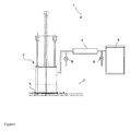
Figure 1 - Displays valve and body leakage control mechanism on an LPG cylinder -
Figure 2 - Elevation of impermeability surface - The pieces in the figures are numbered individually and the fellowing items are represented by the reciprocal numbers.
- 1. A leakage control mechanism for LPG cylinders
- 2. Compartment
- 3. Impermeability surface
- 4. Measuring equipment
- 5. Tank
- 6. Valve
- 7. Cylinder
- A leakage control mechanism for LPG cylinders (7) most basically contains;
- Minimum one leak-proof compartment (2) that allows for measuring the leakage,
- In the leak-proof compartment (2), an impermeability surface (3) which can be in different shapes preferably in conical shape with double o-rings and which creates a lcak-proof environment to isolate the cylinders from the external environment and measure,
- minimum one measuring equipment (4) which measures the pressure difference that would be created by the cylinder after the leak-proof compartment (2) is closed through the movement of the filaments which are included in the sensor group that the compartment contains,
- minimum one compensation tank (5) which ensures a constant external atmospheric pressure and which prevents potential pressure changes, thus ensuring a safe measurement,
- Minimum two discharge valves (6) that open and close in order to discharge the pressure which occurs in the control mechanism,
- and the LPG cylinder (7) which is checked against leakage.
- The invention is related with the leakage control of LPG cylinders with a leakage control mechanism (1) for LPG cylinders. The cylinders (7) on the conveyor line are initially taken into the leak-proof compartment (2). After the cylinder (7) is taken into leak-proof compartment (2), the leak-proof compartment (2) is lowered on the cylinder (7) and the cylinder (7) is isolated from the external environment. A fully impermeable environment is created with the impermeability surface (3). After full impermeability is obtained, the pressure changes of the compartment (2) are measurement by the measuring equipment (4), and the leaking cylinders (7) are automatically removed from the line according to the pressure differences that occur in the case of a leakage. Accordingly, if any point of the cylinder (7) leaks, then the pressure in the leak-proof compartment (2) increases. As a result, a flow occurs due to the positive pressure from the leak-proof compartment (2) to the compensation tank (5). The compensation tank (5) compensates the pressure changes in the external environment and creates an environment with a constant pressure; so the pressure changes in the leak-proof (compartment) are correctly detected by the measuring equipment (4). Measuring equipment (4) detects this flow, that is the leakage which occurs on the cylinder (7). When the identified leakage would be higher than the pre-defined value, the measuring equipment (4) sends a signal to remove the leaking cylinders from the line.
- In the leak-proof compartment (2) of the invention, the cylinder (7) is required to be taken in a completely impermeable volume. The conical and double O-ring surface (3) in the leak-proof compartment (2) isolates the cylinders from the external environment. The section to be controlled is required to be isolated from the environment as fully impermeable. So, the impermeable environment desired for measuring is created. The leak-proof compartment (2) and the impermeability surface (3) play critical roles for the measurement to be realized as free of defects. When impermeability cannot be fully provided, conducting the measurement by the measuring equipment (4) shall not be possible.
- In the mechanism, conical and double O-ring impermeable surface (3) is used to isolate the leak-proof compartment (2) from the external environment. They can be in different sizes, volumes and shapes.
- Discharge valves (6) open during the lowering of the leak-proof compartment (2) in order to compensate the sudden pressure change which occurs during the closure of the leak-proof compartment (2) that includes a leakage control mechanism (1) for LPG cylinders. After the pressure changes are stabilized, the valves (6) are closed and the pressure change in the leak-proof compartment (2) is monitored by the pressure change measuring equipment (4). Compensation tank (5) is used to have a correct measurement. Compensation tank (5) provides a constant atmospheric pressure in the external environment and prevents potential pressure changes.
- The compensation tank (5) of the invention compensates the pressure changes in the external environment and creates an environment with constant pressure. So, the pressure changes in the leak-proof compartment (2) are detected by the measurement equipment (4).
Claims (4)
- In order to use for leak detection of LPG cylinders (7);- minimum one teak-proof compartment (2),- An impermeable surface (3) in leak- proof compartment (2),- a small measuring equipment (4) which is found between the leak-proof compartment (2) and the compensation tank (5), and connected with the valves,- minimum one balancing tank (5) which ensures a constant external atmospheric pressure and which prevents potential pressure changes, thus ensuring a safe measurement,- minimum two discharge valves (6) that open and close in order to discharge the pressure which occurs in the control mechanism,- A leakage control mechanism (I) for LPG cylinders (7) characterized in that it contains a LPG cylinder (7) which is checked against leakage, and minimum one leak-proof compartment (2), in which the cylinder (7) is placed to measure the leakage and which isolates the cylinder (7) from the external environment.
- A leakage control mechanism (1) for LPG cylinders (7) according to Claim 1, characterized in that it contains an impermeability surface (3) which may be in different shapes, preferably in conical shape with double O-rings, and which creates complete impermeability for measurement in the leak-proof compartment (2).
- A leakage control mechanism (1) for LPG cylinders (7) according to Claim 1 and 2 characterized in that it contains minimum one measurement equipment (4) which monitors the pressure changes of the leak-proof compartment (2) after full impermeability is obtained, and which emits the signals that are required for automatically separating leaking cylinders (7) from the line according to the pressure differences that occur in the case of a leakage.
- A leakage control mechanism (1) for LPG cylinders (7) according to Claims 1 to 3 characterized in that it contains a compensation tank (5) which compensates the pressure changes in the external environment and creates an environment with a constant pressure; so the pressure changes in the leak-proof (compartment) are correctly detected by the measuring equipment (4).
Applications Claiming Priority (1)
| Application Number | Priority Date | Filing Date | Title |
|---|---|---|---|
| TR2008/09620A TR200809620A2 (en) | 2008-12-18 | 2008-12-18 | A leak control mechanism for LPG cylinders |
Publications (2)
| Publication Number | Publication Date |
|---|---|
| EP2199655A1 true EP2199655A1 (en) | 2010-06-23 |
| EP2199655B1 EP2199655B1 (en) | 2011-08-31 |
Family
ID=42121942
Family Applications (1)
| Application Number | Title | Priority Date | Filing Date |
|---|---|---|---|
| EP09178694A Not-in-force EP2199655B1 (en) | 2008-12-18 | 2009-12-10 | A leakage control mechanism for LPG cylinders |
Country Status (4)
| Country | Link |
|---|---|
| EP (1) | EP2199655B1 (en) |
| AT (1) | ATE522768T1 (en) |
| DK (1) | DK2199655T3 (en) |
| TR (1) | TR200809620A2 (en) |
Cited By (1)
| Publication number | Priority date | Publication date | Assignee | Title |
|---|---|---|---|---|
| EP2610781A3 (en) * | 2011-12-28 | 2014-08-27 | Aygaz Anonim Sirketi | A cylinder recognition system |
Families Citing this family (1)
| Publication number | Priority date | Publication date | Assignee | Title |
|---|---|---|---|---|
| EP3663633B1 (en) | 2018-12-06 | 2022-09-07 | Carrier Corporation | Systems and methods for controlling gas flow in transportation refrigeration systems |
Citations (7)
| Publication number | Priority date | Publication date | Assignee | Title |
|---|---|---|---|---|
| EP0387542A2 (en) | 1989-03-17 | 1990-09-19 | Repsol-Butano, S.A. | Device for detecting leaks in liquid petroleum gas containers |
| EP0441632A2 (en) | 1990-02-09 | 1991-08-14 | Lambrechts N.V. | Apparatus for detecting micro-leakage of gas from pressurised containers |
| DE4208841C1 (en) * | 1992-03-19 | 1993-08-05 | Deutsche Aerospace Ag, 8000 Muenchen, De | Pressure chamber - has drilling in head of central chamber with synthetic sapphire to allow laser beam through the weld container filling tube |
| DE19622715A1 (en) * | 1995-06-14 | 1997-01-02 | Morton Int Inc | Process for the combined filling of pressure vessels with gas and testing for leaks |
| US5831147A (en) | 1994-02-18 | 1998-11-03 | The Boc Group Plc | Tracer gas leak detection with gross leak detection by measuring differential pressure |
| JP2000352539A (en) | 1999-06-10 | 2000-12-19 | Hitto Kaihatsu Kenkyusho:Kk | Method for correcting measured value of and apparatus for correcting measured value of gas pressure, and method for detecting and apparatus for detecting air leak of sealed container using the same |
| DE10017252A1 (en) * | 2000-03-29 | 2001-10-18 | Hasenkopf Karl Peter | Gas vending system has filling station(s) for filling gas bottles with gas outside reservoir for gas bottles from/to which bottles can be removed/returned under access control |
-
2008
- 2008-12-18 TR TR2008/09620A patent/TR200809620A2/en unknown
-
2009
- 2009-12-10 DK DK09178694.7T patent/DK2199655T3/en active
- 2009-12-10 AT AT09178694T patent/ATE522768T1/en not_active IP Right Cessation
- 2009-12-10 EP EP09178694A patent/EP2199655B1/en not_active Not-in-force
Patent Citations (7)
| Publication number | Priority date | Publication date | Assignee | Title |
|---|---|---|---|---|
| EP0387542A2 (en) | 1989-03-17 | 1990-09-19 | Repsol-Butano, S.A. | Device for detecting leaks in liquid petroleum gas containers |
| EP0441632A2 (en) | 1990-02-09 | 1991-08-14 | Lambrechts N.V. | Apparatus for detecting micro-leakage of gas from pressurised containers |
| DE4208841C1 (en) * | 1992-03-19 | 1993-08-05 | Deutsche Aerospace Ag, 8000 Muenchen, De | Pressure chamber - has drilling in head of central chamber with synthetic sapphire to allow laser beam through the weld container filling tube |
| US5831147A (en) | 1994-02-18 | 1998-11-03 | The Boc Group Plc | Tracer gas leak detection with gross leak detection by measuring differential pressure |
| DE19622715A1 (en) * | 1995-06-14 | 1997-01-02 | Morton Int Inc | Process for the combined filling of pressure vessels with gas and testing for leaks |
| JP2000352539A (en) | 1999-06-10 | 2000-12-19 | Hitto Kaihatsu Kenkyusho:Kk | Method for correcting measured value of and apparatus for correcting measured value of gas pressure, and method for detecting and apparatus for detecting air leak of sealed container using the same |
| DE10017252A1 (en) * | 2000-03-29 | 2001-10-18 | Hasenkopf Karl Peter | Gas vending system has filling station(s) for filling gas bottles with gas outside reservoir for gas bottles from/to which bottles can be removed/returned under access control |
Cited By (1)
| Publication number | Priority date | Publication date | Assignee | Title |
|---|---|---|---|---|
| EP2610781A3 (en) * | 2011-12-28 | 2014-08-27 | Aygaz Anonim Sirketi | A cylinder recognition system |
Also Published As
| Publication number | Publication date |
|---|---|
| ATE522768T1 (en) | 2011-09-15 |
| EP2199655B1 (en) | 2011-08-31 |
| TR200809620A2 (en) | 2010-07-21 |
| DK2199655T3 (en) | 2011-12-19 |
Similar Documents
| Publication | Publication Date | Title |
|---|---|---|
| US4813268A (en) | Leakage detection apparatus for drum wheels and method therefore | |
| DK177454B1 (en) | A method for testing a gas injection valve and a plant for carrying out the method | |
| JP4814330B2 (en) | Method and apparatus for continuous monitoring of gaps in gasoline storage facilities and pipelines | |
| CN110486629A (en) | Air-tightness detection device and method for double fuel host gas pipeline | |
| CN104880538B (en) | Device and method for on-site inspection of online monitor for dissolved gas in transformer oil | |
| CN104122049B (en) | A kind of high pressure airtightness testing method | |
| CN114981631A (en) | Gas leakage detector | |
| CN109781716A (en) | Gas indicator | |
| EP2199655B1 (en) | A leakage control mechanism for LPG cylinders | |
| JP2009198431A (en) | Apparatus and method of inspecting leakage | |
| CN201932715U (en) | Blanking tube and material batching system equipped therewith | |
| CN103776600A (en) | Automatic water filling type leak tester for water pump | |
| KR101613540B1 (en) | Leak tester for high pressure component | |
| KR100832345B1 (en) | Leak rate and life cycles test system of pneumatic angle valve for vacuum | |
| JP5710559B2 (en) | Through-hole closing unit and gas-type leakage inspection apparatus including the same | |
| KR20080099387A (en) | Apparatus and method for testing leak of fuel tank | |
| CN202305148U (en) | Air-tightness detecting instrument for fuel supply system | |
| CN202229892U (en) | Air tightness detection device for opening liquefied petroleum cylinder valve under high pressure | |
| US7500384B2 (en) | Method for controlling the sealing of a tank on an aircraft | |
| CN208223754U (en) | A kind of detecting tool of inlet manifold leakproofness | |
| CN107044992A (en) | A kind of multi-functional CCD visualizations spray igniting composite testing tester | |
| KR20140004014U (en) | Pressure Detecting Apparatus of Pipe for Ship | |
| CN102297751A (en) | Air tightness detection device for high-pressure opened liquefied petroleum gas cylinder valve | |
| JP5766057B2 (en) | Gas leak inspection method | |
| CN103207053B (en) | Windshield Washer leakage inspector |
Legal Events
| Date | Code | Title | Description |
|---|---|---|---|
| PUAI | Public reference made under article 153(3) epc to a published international application that has entered the european phase |
Free format text: ORIGINAL CODE: 0009012 |
|
| AK | Designated contracting states |
Kind code of ref document: A1 Designated state(s): AT BE BG CH CY CZ DE DK EE ES FI FR GB GR HR HU IE IS IT LI LT LU LV MC MK MT NL NO PL PT RO SE SI SK SM TR |
|
| 17P | Request for examination filed |
Effective date: 20101203 |
|
| RIC1 | Information provided on ipc code assigned before grant |
Ipc: F17C 13/12 20060101ALI20110113BHEP Ipc: F17C 5/00 20060101AFI20110113BHEP |
|
| GRAP | Despatch of communication of intention to grant a patent |
Free format text: ORIGINAL CODE: EPIDOSNIGR1 |
|
| GRAS | Grant fee paid |
Free format text: ORIGINAL CODE: EPIDOSNIGR3 |
|
| GRAA | (expected) grant |
Free format text: ORIGINAL CODE: 0009210 |
|
| AK | Designated contracting states |
Kind code of ref document: B1 Designated state(s): AT BE BG CH CY CZ DE DK EE ES FI FR GB GR HR HU IE IS IT LI LT LU LV MC MK MT NL NO PL PT RO SE SI SK SM TR |
|
| REG | Reference to a national code |
Ref country code: CH Ref legal event code: EP Ref country code: GB Ref legal event code: FG4D |
|
| REG | Reference to a national code |
Ref country code: IE Ref legal event code: FG4D |
|
| REG | Reference to a national code |
Ref country code: DE Ref legal event code: R096 Ref document number: 602009002376 Country of ref document: DE Effective date: 20111103 |
|
| REG | Reference to a national code |
Ref country code: DK Ref legal event code: T3 |
|
| REG | Reference to a national code |
Ref country code: NL Ref legal event code: VDEP Effective date: 20110831 |
|
| LTIE | Lt: invalidation of european patent or patent extension |
Effective date: 20110831 |
|
| PG25 | Lapsed in a contracting state [announced via postgrant information from national office to epo] |
Ref country code: NL Free format text: LAPSE BECAUSE OF FAILURE TO SUBMIT A TRANSLATION OF THE DESCRIPTION OR TO PAY THE FEE WITHIN THE PRESCRIBED TIME-LIMIT Effective date: 20110831 Ref country code: LT Free format text: LAPSE BECAUSE OF FAILURE TO SUBMIT A TRANSLATION OF THE DESCRIPTION OR TO PAY THE FEE WITHIN THE PRESCRIBED TIME-LIMIT Effective date: 20110831 Ref country code: HR Free format text: LAPSE BECAUSE OF FAILURE TO SUBMIT A TRANSLATION OF THE DESCRIPTION OR TO PAY THE FEE WITHIN THE PRESCRIBED TIME-LIMIT Effective date: 20110831 Ref country code: IS Free format text: LAPSE BECAUSE OF FAILURE TO SUBMIT A TRANSLATION OF THE DESCRIPTION OR TO PAY THE FEE WITHIN THE PRESCRIBED TIME-LIMIT Effective date: 20111231 Ref country code: FI Free format text: LAPSE BECAUSE OF FAILURE TO SUBMIT A TRANSLATION OF THE DESCRIPTION OR TO PAY THE FEE WITHIN THE PRESCRIBED TIME-LIMIT Effective date: 20110831 Ref country code: SE Free format text: LAPSE BECAUSE OF FAILURE TO SUBMIT A TRANSLATION OF THE DESCRIPTION OR TO PAY THE FEE WITHIN THE PRESCRIBED TIME-LIMIT Effective date: 20110831 Ref country code: NO Free format text: LAPSE BECAUSE OF FAILURE TO SUBMIT A TRANSLATION OF THE DESCRIPTION OR TO PAY THE FEE WITHIN THE PRESCRIBED TIME-LIMIT Effective date: 20111130 |
|
| REG | Reference to a national code |
Ref country code: AT Ref legal event code: MK05 Ref document number: 522768 Country of ref document: AT Kind code of ref document: T Effective date: 20110831 |
|
| PG25 | Lapsed in a contracting state [announced via postgrant information from national office to epo] |
Ref country code: GR Free format text: LAPSE BECAUSE OF FAILURE TO SUBMIT A TRANSLATION OF THE DESCRIPTION OR TO PAY THE FEE WITHIN THE PRESCRIBED TIME-LIMIT Effective date: 20111201 Ref country code: AT Free format text: LAPSE BECAUSE OF FAILURE TO SUBMIT A TRANSLATION OF THE DESCRIPTION OR TO PAY THE FEE WITHIN THE PRESCRIBED TIME-LIMIT Effective date: 20110831 Ref country code: CY Free format text: LAPSE BECAUSE OF FAILURE TO SUBMIT A TRANSLATION OF THE DESCRIPTION OR TO PAY THE FEE WITHIN THE PRESCRIBED TIME-LIMIT Effective date: 20110831 Ref country code: LV Free format text: LAPSE BECAUSE OF FAILURE TO SUBMIT A TRANSLATION OF THE DESCRIPTION OR TO PAY THE FEE WITHIN THE PRESCRIBED TIME-LIMIT Effective date: 20110831 Ref country code: SI Free format text: LAPSE BECAUSE OF FAILURE TO SUBMIT A TRANSLATION OF THE DESCRIPTION OR TO PAY THE FEE WITHIN THE PRESCRIBED TIME-LIMIT Effective date: 20110831 |
|
| PG25 | Lapsed in a contracting state [announced via postgrant information from national office to epo] |
Ref country code: BE Free format text: LAPSE BECAUSE OF FAILURE TO SUBMIT A TRANSLATION OF THE DESCRIPTION OR TO PAY THE FEE WITHIN THE PRESCRIBED TIME-LIMIT Effective date: 20110831 |
|
| PG25 | Lapsed in a contracting state [announced via postgrant information from national office to epo] |
Ref country code: SK Free format text: LAPSE BECAUSE OF FAILURE TO SUBMIT A TRANSLATION OF THE DESCRIPTION OR TO PAY THE FEE WITHIN THE PRESCRIBED TIME-LIMIT Effective date: 20110831 Ref country code: CZ Free format text: LAPSE BECAUSE OF FAILURE TO SUBMIT A TRANSLATION OF THE DESCRIPTION OR TO PAY THE FEE WITHIN THE PRESCRIBED TIME-LIMIT Effective date: 20110831 |
|
| PG25 | Lapsed in a contracting state [announced via postgrant information from national office to epo] |
Ref country code: PL Free format text: LAPSE BECAUSE OF FAILURE TO SUBMIT A TRANSLATION OF THE DESCRIPTION OR TO PAY THE FEE WITHIN THE PRESCRIBED TIME-LIMIT Effective date: 20110831 Ref country code: EE Free format text: LAPSE BECAUSE OF FAILURE TO SUBMIT A TRANSLATION OF THE DESCRIPTION OR TO PAY THE FEE WITHIN THE PRESCRIBED TIME-LIMIT Effective date: 20110831 Ref country code: RO Free format text: LAPSE BECAUSE OF FAILURE TO SUBMIT A TRANSLATION OF THE DESCRIPTION OR TO PAY THE FEE WITHIN THE PRESCRIBED TIME-LIMIT Effective date: 20110831 Ref country code: PT Free format text: LAPSE BECAUSE OF FAILURE TO SUBMIT A TRANSLATION OF THE DESCRIPTION OR TO PAY THE FEE WITHIN THE PRESCRIBED TIME-LIMIT Effective date: 20120102 |
|
| PLBE | No opposition filed within time limit |
Free format text: ORIGINAL CODE: 0009261 |
|
| STAA | Information on the status of an ep patent application or granted ep patent |
Free format text: STATUS: NO OPPOSITION FILED WITHIN TIME LIMIT |
|
| PG25 | Lapsed in a contracting state [announced via postgrant information from national office to epo] |
Ref country code: MC Free format text: LAPSE BECAUSE OF NON-PAYMENT OF DUE FEES Effective date: 20111231 |
|
| 26N | No opposition filed |
Effective date: 20120601 |
|
| REG | Reference to a national code |
Ref country code: IE Ref legal event code: MM4A |
|
| REG | Reference to a national code |
Ref country code: DE Ref legal event code: R097 Ref document number: 602009002376 Country of ref document: DE Effective date: 20120601 |
|
| PG25 | Lapsed in a contracting state [announced via postgrant information from national office to epo] |
Ref country code: IE Free format text: LAPSE BECAUSE OF NON-PAYMENT OF DUE FEES Effective date: 20111210 |
|
| PG25 | Lapsed in a contracting state [announced via postgrant information from national office to epo] |
Ref country code: MK Free format text: LAPSE BECAUSE OF FAILURE TO SUBMIT A TRANSLATION OF THE DESCRIPTION OR TO PAY THE FEE WITHIN THE PRESCRIBED TIME-LIMIT Effective date: 20110831 Ref country code: MT Free format text: LAPSE BECAUSE OF FAILURE TO SUBMIT A TRANSLATION OF THE DESCRIPTION OR TO PAY THE FEE WITHIN THE PRESCRIBED TIME-LIMIT Effective date: 20110831 |
|
| PG25 | Lapsed in a contracting state [announced via postgrant information from national office to epo] |
Ref country code: SM Free format text: LAPSE BECAUSE OF FAILURE TO SUBMIT A TRANSLATION OF THE DESCRIPTION OR TO PAY THE FEE WITHIN THE PRESCRIBED TIME-LIMIT Effective date: 20110831 Ref country code: ES Free format text: LAPSE BECAUSE OF FAILURE TO SUBMIT A TRANSLATION OF THE DESCRIPTION OR TO PAY THE FEE WITHIN THE PRESCRIBED TIME-LIMIT Effective date: 20111211 |
|
| PG25 | Lapsed in a contracting state [announced via postgrant information from national office to epo] |
Ref country code: LU Free format text: LAPSE BECAUSE OF NON-PAYMENT OF DUE FEES Effective date: 20111210 |
|
| PG25 | Lapsed in a contracting state [announced via postgrant information from national office to epo] |
Ref country code: BG Free format text: LAPSE BECAUSE OF FAILURE TO SUBMIT A TRANSLATION OF THE DESCRIPTION OR TO PAY THE FEE WITHIN THE PRESCRIBED TIME-LIMIT Effective date: 20111130 |
|
| PG25 | Lapsed in a contracting state [announced via postgrant information from national office to epo] |
Ref country code: TR Free format text: LAPSE BECAUSE OF FAILURE TO SUBMIT A TRANSLATION OF THE DESCRIPTION OR TO PAY THE FEE WITHIN THE PRESCRIBED TIME-LIMIT Effective date: 20110831 |
|
| PG25 | Lapsed in a contracting state [announced via postgrant information from national office to epo] |
Ref country code: HU Free format text: LAPSE BECAUSE OF FAILURE TO SUBMIT A TRANSLATION OF THE DESCRIPTION OR TO PAY THE FEE WITHIN THE PRESCRIBED TIME-LIMIT Effective date: 20110831 |
|
| REG | Reference to a national code |
Ref country code: CH Ref legal event code: PL |
|
| GBPC | Gb: european patent ceased through non-payment of renewal fee |
Effective date: 20131210 |
|
| PG25 | Lapsed in a contracting state [announced via postgrant information from national office to epo] |
Ref country code: CH Free format text: LAPSE BECAUSE OF NON-PAYMENT OF DUE FEES Effective date: 20131231 Ref country code: LI Free format text: LAPSE BECAUSE OF NON-PAYMENT OF DUE FEES Effective date: 20131231 |
|
| PG25 | Lapsed in a contracting state [announced via postgrant information from national office to epo] |
Ref country code: GB Free format text: LAPSE BECAUSE OF NON-PAYMENT OF DUE FEES Effective date: 20131210 |
|
| REG | Reference to a national code |
Ref country code: FR Ref legal event code: PLFP Year of fee payment: 7 |
|
| REG | Reference to a national code |
Ref country code: FR Ref legal event code: PLFP Year of fee payment: 8 |
|
| REG | Reference to a national code |
Ref country code: FR Ref legal event code: PLFP Year of fee payment: 9 |
|
| PGFP | Annual fee paid to national office [announced via postgrant information from national office to epo] |
Ref country code: IT Payment date: 20181220 Year of fee payment: 10 |
|
| PGFP | Annual fee paid to national office [announced via postgrant information from national office to epo] |
Ref country code: FR Payment date: 20191220 Year of fee payment: 11 Ref country code: DK Payment date: 20191227 Year of fee payment: 11 |
|
| REG | Reference to a national code |
Ref country code: DE Ref legal event code: R119 Ref document number: 602009002376 Country of ref document: DE |
|
| PG25 | Lapsed in a contracting state [announced via postgrant information from national office to epo] |
Ref country code: DE Free format text: LAPSE BECAUSE OF NON-PAYMENT OF DUE FEES Effective date: 20200701 Ref country code: IT Free format text: LAPSE BECAUSE OF NON-PAYMENT OF DUE FEES Effective date: 20191210 |
|
| REG | Reference to a national code |
Ref country code: DK Ref legal event code: EBP Effective date: 20201231 |
|
| PG25 | Lapsed in a contracting state [announced via postgrant information from national office to epo] |
Ref country code: FR Free format text: LAPSE BECAUSE OF NON-PAYMENT OF DUE FEES Effective date: 20201231 |
|
| PG25 | Lapsed in a contracting state [announced via postgrant information from national office to epo] |
Ref country code: DK Free format text: LAPSE BECAUSE OF NON-PAYMENT OF DUE FEES Effective date: 20201231 |