EP2199637B1 - Procédé de surveillance d'une commande d'engrenage hydraulique ou pneumatique - Google Patents
Procédé de surveillance d'une commande d'engrenage hydraulique ou pneumatique Download PDFInfo
- Publication number
- EP2199637B1 EP2199637B1 EP09176039A EP09176039A EP2199637B1 EP 2199637 B1 EP2199637 B1 EP 2199637B1 EP 09176039 A EP09176039 A EP 09176039A EP 09176039 A EP09176039 A EP 09176039A EP 2199637 B1 EP2199637 B1 EP 2199637B1
- Authority
- EP
- European Patent Office
- Prior art keywords
- pressure
- supply
- clutch
- threshold
- friction clutch
- Prior art date
- Legal status (The legal status is an assumption and is not a legal conclusion. Google has not performed a legal analysis and makes no representation as to the accuracy of the status listed.)
- Active
Links
Images
Classifications
-
- F—MECHANICAL ENGINEERING; LIGHTING; HEATING; WEAPONS; BLASTING
- F16—ENGINEERING ELEMENTS AND UNITS; GENERAL MEASURES FOR PRODUCING AND MAINTAINING EFFECTIVE FUNCTIONING OF MACHINES OR INSTALLATIONS; THERMAL INSULATION IN GENERAL
- F16H—GEARING
- F16H61/00—Control functions within control units of change-speed- or reversing-gearings for conveying rotary motion ; Control of exclusively fluid gearing, friction gearing, gearings with endless flexible members or other particular types of gearing
- F16H61/12—Detecting malfunction or potential malfunction, e.g. fail safe; Circumventing or fixing failures
-
- F—MECHANICAL ENGINEERING; LIGHTING; HEATING; WEAPONS; BLASTING
- F16—ENGINEERING ELEMENTS AND UNITS; GENERAL MEASURES FOR PRODUCING AND MAINTAINING EFFECTIVE FUNCTIONING OF MACHINES OR INSTALLATIONS; THERMAL INSULATION IN GENERAL
- F16D—COUPLINGS FOR TRANSMITTING ROTATION; CLUTCHES; BRAKES
- F16D48/00—External control of clutches
- F16D48/06—Control by electric or electronic means, e.g. of fluid pressure
- F16D48/066—Control of fluid pressure, e.g. using an accumulator
-
- F—MECHANICAL ENGINEERING; LIGHTING; HEATING; WEAPONS; BLASTING
- F16—ENGINEERING ELEMENTS AND UNITS; GENERAL MEASURES FOR PRODUCING AND MAINTAINING EFFECTIVE FUNCTIONING OF MACHINES OR INSTALLATIONS; THERMAL INSULATION IN GENERAL
- F16H—GEARING
- F16H59/00—Control inputs to control units of change-speed-, or reversing-gearings for conveying rotary motion
- F16H59/68—Inputs being a function of gearing status
-
- F—MECHANICAL ENGINEERING; LIGHTING; HEATING; WEAPONS; BLASTING
- F16—ENGINEERING ELEMENTS AND UNITS; GENERAL MEASURES FOR PRODUCING AND MAINTAINING EFFECTIVE FUNCTIONING OF MACHINES OR INSTALLATIONS; THERMAL INSULATION IN GENERAL
- F16D—COUPLINGS FOR TRANSMITTING ROTATION; CLUTCHES; BRAKES
- F16D2500/00—External control of clutches by electric or electronic means
- F16D2500/10—System to be controlled
- F16D2500/102—Actuator
- F16D2500/1026—Hydraulic
-
- F—MECHANICAL ENGINEERING; LIGHTING; HEATING; WEAPONS; BLASTING
- F16—ENGINEERING ELEMENTS AND UNITS; GENERAL MEASURES FOR PRODUCING AND MAINTAINING EFFECTIVE FUNCTIONING OF MACHINES OR INSTALLATIONS; THERMAL INSULATION IN GENERAL
- F16D—COUPLINGS FOR TRANSMITTING ROTATION; CLUTCHES; BRAKES
- F16D2500/00—External control of clutches by electric or electronic means
- F16D2500/30—Signal inputs
- F16D2500/302—Signal inputs from the actuator
- F16D2500/3024—Pressure
-
- F—MECHANICAL ENGINEERING; LIGHTING; HEATING; WEAPONS; BLASTING
- F16—ENGINEERING ELEMENTS AND UNITS; GENERAL MEASURES FOR PRODUCING AND MAINTAINING EFFECTIVE FUNCTIONING OF MACHINES OR INSTALLATIONS; THERMAL INSULATION IN GENERAL
- F16D—COUPLINGS FOR TRANSMITTING ROTATION; CLUTCHES; BRAKES
- F16D2500/00—External control of clutches by electric or electronic means
- F16D2500/50—Problem to be solved by the control system
- F16D2500/51—Relating safety
- F16D2500/5108—Failure diagnosis
-
- F—MECHANICAL ENGINEERING; LIGHTING; HEATING; WEAPONS; BLASTING
- F16—ENGINEERING ELEMENTS AND UNITS; GENERAL MEASURES FOR PRODUCING AND MAINTAINING EFFECTIVE FUNCTIONING OF MACHINES OR INSTALLATIONS; THERMAL INSULATION IN GENERAL
- F16D—COUPLINGS FOR TRANSMITTING ROTATION; CLUTCHES; BRAKES
- F16D2500/00—External control of clutches by electric or electronic means
- F16D2500/70—Details about the implementation of the control system
- F16D2500/704—Output parameters from the control unit; Target parameters to be controlled
- F16D2500/70402—Actuator parameters
- F16D2500/70406—Pressure
-
- F—MECHANICAL ENGINEERING; LIGHTING; HEATING; WEAPONS; BLASTING
- F16—ENGINEERING ELEMENTS AND UNITS; GENERAL MEASURES FOR PRODUCING AND MAINTAINING EFFECTIVE FUNCTIONING OF MACHINES OR INSTALLATIONS; THERMAL INSULATION IN GENERAL
- F16H—GEARING
- F16H59/00—Control inputs to control units of change-speed-, or reversing-gearings for conveying rotary motion
- F16H59/68—Inputs being a function of gearing status
- F16H2059/683—Sensing pressure in control systems or in fluid controlled devices, e.g. by pressure sensors
-
- F—MECHANICAL ENGINEERING; LIGHTING; HEATING; WEAPONS; BLASTING
- F16—ENGINEERING ELEMENTS AND UNITS; GENERAL MEASURES FOR PRODUCING AND MAINTAINING EFFECTIVE FUNCTIONING OF MACHINES OR INSTALLATIONS; THERMAL INSULATION IN GENERAL
- F16H—GEARING
- F16H61/00—Control functions within control units of change-speed- or reversing-gearings for conveying rotary motion ; Control of exclusively fluid gearing, friction gearing, gearings with endless flexible members or other particular types of gearing
- F16H61/12—Detecting malfunction or potential malfunction, e.g. fail safe; Circumventing or fixing failures
- F16H2061/1256—Detecting malfunction or potential malfunction, e.g. fail safe; Circumventing or fixing failures characterised by the parts or units where malfunctioning was assumed or detected
- F16H2061/1284—Detecting malfunction or potential malfunction, e.g. fail safe; Circumventing or fixing failures characterised by the parts or units where malfunctioning was assumed or detected the failing part is a sensor
Definitions
- the invention relates to a method for monitoring a hydraulic or pneumatic transmission control, which has a pressure supply part with a supply line, which carries a standing under a supply pressure pressure medium, and with an actuating part of a clutch actuator of a friction clutch, wherein the actuating part has a pressure chamber, which has an associated Coupling control valve is connectable to the supply line, and wherein the supply pressure is determined by means of a connectable via a control valve to the supply line pressure sensor.
- a hydraulic or pneumatic transmission control of an automated manual transmission usually has a pressure supply part and an actuating part.
- the pressure supply part a supply pressure is generated in a supply line and maintained at a predetermined pressure level.
- the actuating part usually comprises actuators designed as a single-acting or double-acting actuating cylinder, such as a clutch actuator and a plurality of transmission actuators, the pressure chambers of which can be pressure-filled via associated control valves as required by a connection to the supply line or emptied by a connection to a pressure-free line leading to a pressure-medium sink ,
- the oil sump can serve as a pressure medium sink
- the exhaust air can be discharged via the pressure-free line to the ambient air.
- a typical hydraulic transmission control of an automated manual transmission for example, in DE 198 49 488 C2 described.
- the pressure supply part of this known transmission control has an oil pump drivable by an electric motor, by means of the hydraulic oil by a Filter element from an oil sump and is conveyed through a check valve in a supply line.
- a pressure relief valve is connected to the supply line, can flow through the excess hydraulic oil back into the oil sump.
- an accumulator connected to the supply line is provided.
- a pressure sensor is connected to the supply line.
- the actuating part of this known transmission control on the one hand has a designed as a single-acting actuator cylinder and controllable via an associated clutch control valve clutch actuator for engagement and disengagement of a trained as a diaphragm spring clutch friction clutch.
- the actuating part comprises a selector plate designed as a single-acting actuating cylinder and controllable via an associated selector control valve and a selector plate which can be controlled as a double-acting actuating cylinder and is controlled via two associated selector control valves.
- a controllable by the control pressure of the clutch actuator shut-off valve is provided by the actuation of the selector and the switch actuator is only possible when disengaged friction clutch.
- a position sensor of the piston rod of the clutch actuator is provided. In the event of a defect in the pressure sensor, the supply pressure can no longer be determined, and the transmission control must then immediately switch to an emergency operation, although the supply pressure prevailing in the supply line can still be sufficiently high to ensure normal operation for at least a certain period of time.
- a transmission control of an automated manual transmission is known in which the actuating device a Has selector and a switch actuator, which are each designed as a double-acting actuator cylinder.
- this transmission control according to the local Fig. 9 is a pressure chamber of the selector and a pressure chamber of the switch actuator each associated with an associated selector or switching control valve immediately upstream.
- the respective other pressure chamber of the selector and the switch actuator and the selector control valve and the switching control valve is preceded by a common main control valve via which the respective distribution line is selectively connectable to the supply line of the pressure supply part or with a leading to the oil sump pressure-free line.
- a pressure sensor is connected, the pressure signal is used via the control of the control valves substantially for controlling the selector and the switch actuator.
- the supply pressure prevailing in the supply line can also be determined when the main control valve is fully opened to the supply line and the selector control valve and the switching control valve are each in their closed zero position.
- the present invention seeks to propose a method for monitoring a hydraulic or pneumatic transmission control of the type mentioned, with the prevailing in the supply line supply pressure without special design precautions on the transmission control means of a connectable via a control valve to the supply line pressure sensor can be determined.
- the source pressure p Q present in the pressure source can be calculated from the control pressure p S and the pressure increase ⁇ p S or the pressure gradient ⁇ p S / ⁇ t in the pressure space.
- this principle for determining a higher swelling pressure p Q is applicable to all hydraulic or pneumatic controls in which a pressure sensor is arranged downstream of the pressure source by a control valve.
- the invention therefore relates to a method for monitoring a hydraulic or pneumatic transmission control, which has a pressure supply part with a supply line, which carries a standing under a supply pressure pressure medium, as well as with an actuating part a clutch actuator of a friction clutch, wherein the actuating part has a pressure chamber, which is connectable via an associated clutch control valve to the supply line, and wherein the supply pressure is determined by means of a connectable via a control valve to the supply line pressure sensor.
- the currently prevailing in the supply line of the pressure supply part of a hydraulic or pneumatic transmission control supply pressure p V from the pressure prevailing in the pressure chamber of the clutch actuator actuating pressure p K and from the pressure increase ⁇ p generated by a brief opening of the clutch control valve K and / or pressure gradient .DELTA.p K / .DELTA.t of the control pressure p K is calculated, wherein the control pressure p K , the pressure increase .DELTA.p K and / or the pressure gradient .DELTA.p K / .DELTA.t are detected by means connected to the pressure chamber of the clutch actuator pressure sensor.
- the method according to the invention does not require any special constructional provisions on the pressure supply part or the actuating part of the transmission control and can be used as an emergency procedure, ie in the event of a defect of a pressure sensor connected to the supply line, as well as as a standard method, i. when saving a pressure sensor connected to the supply line.
- a corresponding hydraulic or pneumatic clutch control which may also be part of a transmission control, for example, in two embodiments of the DE 10 2006 014 141 A1 known.
- the pressure sensor connected to the pressure chamber of the clutch actuator is used only for controlling the friction clutch.
- the coarse control of the friction clutch is controlled away, ie by means of the path signal a position sensor of the piston rod of the clutch actuator tapping displacement sensor, and the fine control of the friction clutch pressure controlled, ie by means of the pressure signal of the pressure prevailing in the pressure chamber of the clutch actuator control pressure sensor takes place.
- the determination of the supply pressure p V is preferably at the beginning of a starting or circuit-related disengagement of the friction clutch after a pre-filling of the clutch actuator.
- pre-filling of the pressure chamber of the clutch actuator thereby distorted distortions in the determination of the supply pressure p V are avoided.
- subsequent pressure increase .DELTA.p K for determining the supply pressure p V does not delay the intended disengagement process, since the further increase of the control pressure p K for disengaging the friction clutch can take place immediately thereafter.
- the determination of the supply pressure p V in a passively closable friction clutch erfofgt preferably in operating phases with fully engaged friction clutch with a previous pre-filling and a subsequent depressurization of the clutch actuator.
- the determination of the supply pressure p V takes place in this case at engaged with Matteranpressung friction clutch, so that the slight increase of the control pressure p K can not lead to disengagement or slippage of the friction clutch.
- the previous pre-filling of the clutch actuator is used to increase the accuracy of the determined supply pressure p V , and by the subsequent depressurization of the clutch actuator, the output state is restored with fully engaged friction clutch.
- the determination of the supply pressure p V is preferably at the end of a starting or circuit-related engagement of the friction clutch before reaching the intended maximum pressure of the clutch actuator, ie in the range of Kochanpressung, without thereby the relevant start-up or switching process is delayed.
- the determination of the supply pressure p V in an actively closable friction clutch is preferably carried out in operating phases with fully engaged friction clutch with a previous pressure reduction of the clutch actuator.
- the determination of the supply pressure is thus also carried out in the range of Studentsanpressung, being automatically reached again by the previous pressure reduction and the subsequent pressure increase ⁇ p K provided for the Kochanpressung the friction clutch actuating pressure pK.
- calculation parameters are required by means of which eg the influence of the geometry of the throttle cross-section of the briefly opened clutch control valve or the influence of the Toughness of the pressure medium on the pressure increase ⁇ p K and thus be taken into account on the calculated supply pressure p V can.
- the determination of at least one such calculation parameter for calculating the supply pressure p V from the sensory pressure increase ⁇ p K and / or pressure gradient ⁇ p K / ⁇ t of the control pressure p K can be carried out expediently within the scope of a teach-in process of the transmission control, ie during the initial commissioning of the motor vehicle at the vehicle manufacturer or at a restart of the motor vehicle after a major repair in a service workshop. It is also conceivable that the determination of at least one such calculation parameter can take place after each engine start.
- the calculated supply pressure p V can be compared with at least one pressure threshold P SW1 , P SW2 , P SW3 that can be applied to the respective transmission control, and depending on the magnitude of the supply pressure p V relative to the pressure threshold p SW1 , p SW2 , p SW3 at least one safety function is executed.
- a current leakage volume flow Q L is determined from the calculated supply pressure p V and the height of the leakage volume flow Q L is compared with at least one applicable leakage threshold Q SW1 , Q SW2 , Q SW3 , and that dependent From the height of the leakage volume flow Q L with respect to the leakage threshold Q SW1 , Q SW2, Q SW3 , ie when a maximum permissible leakage is exceeded, at least one safety function is performed.
- the transmission can be switched to its neutral position when the supply pressure p V has reached or fallen below the mean pressure threshold P SW2 , or when the leakage volume flow Q L has reached or exceeded the mean leakage threshold Q SW2 .
- an audible and / or visual warning signal such as the sounding of a periodically interrupted warning tone, the flashing of a warning light and / or the display of a corresponding error message in a display, output when the supply pressure p V is an upper pressure threshold P SW3 has reached or fallen below, or if the leakage volume flow Q L has reached or exceeded a lower leakage threshold Q SW1 .
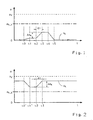
- valid pressure curve of the control pressure p K of an associated clutch actuator refers to the inventive determination of the supply pressure p V of the pressure supply part of a hydraulic or pneumatic transmission control during driving with fully engaged friction clutch, ie largely unpressurized clutch actuator.
- control pressure p K which during the period .DELTA.t achieved in the pressure chamber pressure increase .DELTA.p K , and optionally recorded in this period pressure gradient .DELTA.p K / .DELTA.t detected, and from below Use analytically and / or experimentally determined calculation parameters of prevailing in the supply line supply pressure p V calculated.
- Fig. 2 schematically illustrated and for an actively closable friction clutch, such as a multi-plate clutch, valid pressure curve of the control pressure p K of an associated clutch actuator also relates to the inventive determination of the supply pressure p V of the pressure supply part of a hydraulic or pneumatic transmission control during driving with fully engaged friction clutch, which in this case corresponds to a below the maximum actuating pressure p K clutch actuator.
- control pressure p K present at the time t 2 the pressure increase ⁇ p K achieved during the time interval ⁇ t in the pressure chamber and, if appropriate, the pressure gradient ⁇ p K / ⁇ t recorded in this time period are detected by means of a pressure sensor connected to the pressure chamber of the clutch actuator and subsequently referred to below Use analytically and / or experimentally determined calculation parameters of prevailing in the supply line supply pressure p V calculated.
- the previous pressure reduction is dimensioned such that it corresponds in magnitude to the pressure increase ⁇ p K generated to determine the supply pressure p V , so that the friction clutch is fully engaged again at time t3 without further measures with appropriate overpressure. Since the height of the reduced by the pressure reduction pitch pressure p K is far above the slip limit p K_S the friction clutch, the friction clutch does not slip, so that the driving operation is not disturbed by the procedure in this case.
Claims (14)
- Procédé de surveillance d'une commande d'engrenage hydraulique ou pneumatique, qui présente une partie d'alimentation en pression avec une conduite d'alimentation, qui conduit un fluide sous pression à une pression d'alimentation (pv), et avec une partie d'actionnement d'un actionneur d'embrayage d'un embrayage à friction, la partie d'actionnement présentant un espace de pression qui peut être connecté à la conduite d'alimentation par le biais d'une soupape de commande d'embrayage associée, et dans lequel la pression d'alimentation (pv) est déterminée au moyen d'un capteur de pression pouvant être connecté par le biais d'une soupape de commande à la conduite d'alimentation, caractérisé en ce que la pression d'alimentation (pv) est déterminée au moyen d'un capteur de pression raccordé à l'espace de pression de l'actionneur d'embrayage, en produisant une augmentation de pression (ΔpK) et/ou un gradient de pression (ΔpK/Δt) de la pression de commande (pK) dans l'espace de pression de l'actionneur d'embrayage par une brève ouverture de la soupape de commande d'embrayage, et en calculant la pression d'alimentation actuellement présente (pv) à partir de la pression de commande (pK) détectée au moyen du capteur de pression ainsi que de l'augmentation de pression (ΔpK) et/ou du gradient de pression (ΔpK/Δt).
- Procédé selon la revendication 1, caractérisé en ce que juste avant ou après l'ouverture de la soupape de commande d'embrayage pour la détermination de la pression d'alimentation (pv), une chute (ΔpK) de la pression de commande (pK) est produite par une brève connexion de l'espace de pression de l'actionneur d'embrayage à une conduite sans pression, laquelle chute de pression correspond en valeur absolue approximativement à l'augmentation (ΔpK) de la pression de commande (pK) par l'ouverture de la soupape de commande d'embrayage.
- Procédé selon la revendication 1 ou 2, caractérisé en ce que la détermination de la pression d'alimentation (pv) a lieu après un préremplissage de l'actionneur d'embrayage dans le cas d'un embrayage à friction à fermeture passive, au début d'un débrayage de l'embrayage à friction provoqué par un démarrage ou un changement de vitesse.
- Procédé selon l'une quelconque des revendications 1 à 3, caractérisé en ce que la détermination de la pression d'alimentation (pv) a lieu dans le cas d'un embrayage à friction à fermeture passive, pendant le mode de conduite dans des phases de fonctionnement avec l'embrayage à friction complètement embrayé avec un préremplissage préalable et un changement de vitesse sans pression subséquent de l'actionneur d'embrayage.
- Procédé selon la revendication 1 ou 2, caractérisé en ce que la détermination de la pression d'alimentation (pv) a lieu, dans le cas d'un embrayage à friction à fermeture active, à la fin d'un embrayage de l'embrayage à friction provoqué par un démarrage ou un changement de vitesse, avant d'atteindre la pression maximale prévue pour l'actionneur d'embrayage.
- Procédé selon l'une quelconque des revendications 1, 2 ou 5, caractérisé en ce que la détermination de la pression d'alimentation (pv) a lieu, dans le cas d'un embrayage à friction à fermeture active, pendant le mode de conduite dans des phases de fonctionnement avec l'embrayage à friction complètement embrayé avec une réduction de pression préalable de l'actionneur d'embrayage.
- Procédé selon l'une quelconque des revendications 1 à 6, caractérisé en ce qu'au moins un paramètre de calcul pour le calcul de la pression d'alimentation (pv) est déterminé à partir de l'augmentation de la pression détectée par capteur (ΔpK) et/ou d'un gradient de pression (ΔpK/Δt) de la pression de commande (pK) dans le cadre d'une opération d'apprentissage de la commande d'engrenage.
- Procédé selon l'une quelconque des revendications 1 à 7, caractérisé en ce que la pression d'alimentation calculée (pv) est comparée avec au moins un seuil de pression applicable (pSW1, pSW2, pSW3), et en ce qu'au moins une fonction de sécurité est mise en oeuvre en fonction du niveau de la pression d'alimentation (pv) par rapport au seuil de pression (pSW1, pSW2, pSW3).
- Procédé selon l'une quelconque des revendications 1 à 7, caractérisé en ce que l'on détermine à partir de la pression d'alimentation calculée (pv), un débit volumique de fuite actuel (QL) et l'on compare le niveau du débit volumique de fuite (QL) avec au moins un seuil de fuite applicable (QSW1, QSW2, QSW3), et en ce qu'en fonction du niveau du débit volumique de fuite (QL) par rapport au seuil de fuite (QSW1, QSW2, QSW3), on met en oeuvre au moins une fonction de sécurité.
- Procédé selon la revendication 8 ou 9, caractérisé en ce qu'à l'arrêt du véhicule, l'enclenchement d'une vitesse de démarrage est bloqué, si la pression d'alimentation (pv) a atteint ou est descendue en dessous d'un seuil de pression moyen (pSW2), ou si le débit volumique de fuite (QL) a atteint ou a dépassé un seuil de fuite moyen (QSW2).
- Procédé selon l'une quelconque des revendications 8 à 10, caractérisé en ce qu'à l'arrêt du véhicule, une opération de démarrage se terminant est interrompue, et l'engrenage de changement de vitesse est commuté dans sa position neutre, lorsque la pression d'alimentation (pv) a atteint ou est descendue en dessous d'un seuil de pression inférieur (pSW1), ou si le débit volumique de fuite (QL) a atteint ou a dépassé un seuil de fuite supérieur (QSW3).
- Procédé selon l'une quelconque des revendications 8 à 11, caractérisé en ce que pendant la conduite, l'engrenage de changement de vitesse est commuté dans sa position neutre, si la pression d'alimentation (pv) a atteint ou est descendue en dessous du seuil de pression moyen (pSW2), ou si le débit volumique de fuite (QL) a atteint ou a dépassé le seuil de fuite moyen (QSW2).
- Procédé selon la revendication 11 ou 12, caractérisé en ce que l'engrenage de changement de vitesse est commuté dans sa position neutre lorsque l'embrayage à friction est fermé, le moteur d'entraînement étant maintenu sans couple pendant la sortie de la vitesse enclenchée par une commande de moteur spécialement conçue à cet égard.
- Procédé selon l'une quelconque des revendications 8 à 13, caractérisé en ce que pour avertir le conducteur, un signal d'avertissement acoustique et/ou optique est délivré, si la pression d'alimentation (pv) a atteint ou est descendue en dessous d'un seuil de pression supérieur (pSW3), ou si le débit volumique de fuite (QL) a atteint ou a dépassé un seuil de fuite inférieur (QSW1).
Applications Claiming Priority (1)
| Application Number | Priority Date | Filing Date | Title |
|---|---|---|---|
| DE102008054662A DE102008054662A1 (de) | 2008-12-15 | 2008-12-15 | Verfahren zur Überwachung einer hydraulischen oder pneumatischen Getriebesteuerung |
Publications (2)
| Publication Number | Publication Date |
|---|---|
| EP2199637A1 EP2199637A1 (fr) | 2010-06-23 |
| EP2199637B1 true EP2199637B1 (fr) | 2011-03-16 |
Family
ID=41728413
Family Applications (1)
| Application Number | Title | Priority Date | Filing Date |
|---|---|---|---|
| EP09176039A Active EP2199637B1 (fr) | 2008-12-15 | 2009-11-16 | Procédé de surveillance d'une commande d'engrenage hydraulique ou pneumatique |
Country Status (4)
| Country | Link |
|---|---|
| US (1) | US8162799B2 (fr) |
| EP (1) | EP2199637B1 (fr) |
| AT (1) | ATE502226T1 (fr) |
| DE (2) | DE102008054662A1 (fr) |
Families Citing this family (4)
| Publication number | Priority date | Publication date | Assignee | Title |
|---|---|---|---|---|
| DE102010002764A1 (de) * | 2010-03-11 | 2011-09-15 | Zf Friedrichshafen Ag | Verfahren zur Steuerung einer Getriebebremse |
| DE102015210668A1 (de) * | 2015-06-11 | 2016-12-15 | Zf Friedrichshafen Ag | Verfahren zur Erkennung einer Fehlerleckage in einem pneumatischen Stellsystem eines Getriebes und Steuergerät zur Durchführung des Verfahrens |
| DE102015220758B4 (de) | 2015-10-23 | 2022-10-06 | Zf Friedrichshafen Ag | Verfahren und Steuergerät zum Betreiben eines Kraftfahrzeugs |
| DE102017115484B3 (de) * | 2017-07-11 | 2018-11-22 | Schaeffler Technologies AG & Co. KG | Verfahren zur Steuerung eines Aktors sowie Kraftfahrzeug mit einem Aktor |
Family Cites Families (12)
| Publication number | Priority date | Publication date | Assignee | Title |
|---|---|---|---|---|
| US3803843A (en) * | 1971-08-16 | 1974-04-16 | Sundstrand Corp | Hydromechanical transmission |
| JPH086797B2 (ja) * | 1986-07-15 | 1996-01-29 | 本田技研工業株式会社 | 車両用無段変速機の変速制御方法 |
| EP0321622A1 (fr) * | 1987-12-23 | 1989-06-28 | Honda Giken Kogyo Kabushiki Kaisha | Dispositif de commande d'une transmission continue de vitesse pour véhicule automobile |
| EP0417283B1 (fr) * | 1988-05-31 | 1997-08-06 | Kabushiki Kaisha Komatsu Seisakusho | Transmission mecanique-hydraulique intermediaire et procede de commande de cette transmission |
| US5575735A (en) * | 1995-04-06 | 1996-11-19 | Caterpillar Inc. | Integrated power transmitting system |
| JPH10507256A (ja) | 1995-07-26 | 1998-07-14 | エーピー・コンスバーグ・リミテッド | 比選択機構 |
| GB9810793D0 (en) | 1998-05-20 | 1998-07-15 | Kongsberg Techmatic Uk Ltd | Variable pressure hydraulic systems |
| DE19834765A1 (de) * | 1998-08-01 | 2000-02-03 | Hydraulik Ring Gmbh | Hydrauliksystem zum Betätigen von wenigstens zwei Funktionsbereichen in einem Fahrzeug |
| DE19849488C2 (de) | 1998-10-27 | 2000-11-30 | Mannesmann Sachs Ag | Hydraulische Betätigungseinrichtung zur Betätigung einer Reibungskupplung und eines automatisierten Schaltgetriebes |
| DE19931973A1 (de) * | 1999-07-09 | 2001-01-11 | Wabco Gmbh & Co Ohg | Einrichtung zum Steuern einer Stelleinrichtung für ein Getriebe |
| WO2005010409A1 (fr) * | 2003-07-25 | 2005-02-03 | Continental Teves Ag & Co. Ohg | Circuit hydraulique |
| DE102006014141A1 (de) * | 2006-03-28 | 2007-10-04 | Zf Friedrichshafen Ag | Verfahren zur Steuerung einer automatisierten Reibungskupplung |
-
2008
- 2008-12-15 DE DE102008054662A patent/DE102008054662A1/de not_active Withdrawn
-
2009
- 2009-11-16 EP EP09176039A patent/EP2199637B1/fr active Active
- 2009-11-16 DE DE502009000458T patent/DE502009000458D1/de active Active
- 2009-11-16 AT AT09176039T patent/ATE502226T1/de active
- 2009-12-07 US US12/632,082 patent/US8162799B2/en not_active Expired - Fee Related
Also Published As
| Publication number | Publication date |
|---|---|
| DE502009000458D1 (de) | 2011-04-28 |
| ATE502226T1 (de) | 2011-04-15 |
| EP2199637A1 (fr) | 2010-06-23 |
| DE102008054662A1 (de) | 2010-06-17 |
| US20100151992A1 (en) | 2010-06-17 |
| US8162799B2 (en) | 2012-04-24 |
Similar Documents
| Publication | Publication Date | Title |
|---|---|---|
| EP2999904B1 (fr) | Procédé pour système hydraulique destiné à une boîte de vitesses à double embrayage | |
| EP2047133B1 (fr) | Système d'accouplement | |
| EP2310710B1 (fr) | Système de débrayage et procédé de fonctionnement d'un système de débrayage | |
| DE112012001711B4 (de) | Verfahren zur Inbetriebnahme einer Kupplung | |
| DE102013008741B3 (de) | Hydrauliksystem für ein Doppelkupplungsgetriebe eines Kraftfahrzeugs | |
| EP2024665A1 (fr) | Dispositif de transmission d'un véhicule automobile | |
| DE102005012261A1 (de) | Verfahren und Vorrichtung zur Steuerung eines Kraftfahrzeug-Antriebsstranges | |
| EP3494328B1 (fr) | Système hydraulique pour une transmission automatique d'un véhicule à moteur | |
| DE102012220178B4 (de) | Verfahren zur Fehlerdetektierung in einem hydraulischen Kupplungsbetätigungssystem | |
| EP3494331B1 (fr) | Système hydraulique pour une boîte de vitesses automatique d'un véhicule automobile | |
| EP2199637B1 (fr) | Procédé de surveillance d'une commande d'engrenage hydraulique ou pneumatique | |
| DE102008057656A1 (de) | Kupplungssystem | |
| DE102011017516A1 (de) | Verfahren zur Bestimmung von Kenngrößen eines Automatikgetriebes | |
| DE102009016440A1 (de) | Getriebeschaltvorrichtung | |
| DE102014215753A1 (de) | Steuern eines Kupplungsaktuators | |
| DE102016214370B3 (de) | Hydrauliksystem für ein Automatikgetriebe eines Kraftfahrzeugs | |
| DE102009059081A1 (de) | Verfahren zum hydraulischen Betätigen einer Kupplung | |
| EP0710580A1 (fr) | Dispositif d'embrayage d'urgence | |
| DE102007009542B4 (de) | Verfahren zur Ansteuerung eines Druckmittelverbrauchers unter Verwendung eines Druckdifferenzsensors und Steuervorrichtung | |
| DE102014008157A1 (de) | Getriebevorrichtung für ein Kraftfahrzeug | |
| DE102012201145A1 (de) | Verfahren zum Überprüfen eines Notlaufzustandes bei einem Getriebe | |
| DE102011014573A1 (de) | Verfahren zum Steuern einer automatisierten Kupplung | |
| EP1855022B1 (fr) | Procédé et opération d'un appareil à embrayage automatique | |
| DE102012221977A1 (de) | Kupplungsbetätigung | |
| DE102020200383B4 (de) | Verfahren zum Betätigen einer Reibkupplung eines Antriebsstranges eines motorbetriebenen Wasserfahrzeugs, sowie Steuergerät zur Regelung einer Betätigung einer Reibkupplung |
Legal Events
| Date | Code | Title | Description |
|---|---|---|---|
| PUAI | Public reference made under article 153(3) epc to a published international application that has entered the european phase |
Free format text: ORIGINAL CODE: 0009012 |
|
| AK | Designated contracting states |
Kind code of ref document: A1 Designated state(s): AT BE BG CH CY CZ DE DK EE ES FI FR GB GR HR HU IE IS IT LI LT LU LV MC MK MT NL NO PL PT RO SE SI SK SM TR |
|
| AX | Request for extension of the european patent |
Extension state: AL BA RS |
|
| 17P | Request for examination filed |
Effective date: 20100831 |
|
| GRAP | Despatch of communication of intention to grant a patent |
Free format text: ORIGINAL CODE: EPIDOSNIGR1 |
|
| RIC1 | Information provided on ipc code assigned before grant |
Ipc: F16H 61/12 20100101ALI20100927BHEP Ipc: F16H 61/00 20060101ALI20100927BHEP Ipc: F16D 48/06 20060101AFI20100927BHEP |
|
| GRAS | Grant fee paid |
Free format text: ORIGINAL CODE: EPIDOSNIGR3 |
|
| GRAA | (expected) grant |
Free format text: ORIGINAL CODE: 0009210 |
|
| AK | Designated contracting states |
Kind code of ref document: B1 Designated state(s): AT BE BG CH CY CZ DE DK EE ES FI FR GB GR HR HU IE IS IT LI LT LU LV MC MK MT NL NO PL PT RO SE SI SK SM TR |
|
| REG | Reference to a national code |
Ref country code: GB Ref legal event code: FG4D Free format text: NOT ENGLISH |
|
| REG | Reference to a national code |
Ref country code: CH Ref legal event code: EP |
|
| REG | Reference to a national code |
Ref country code: IE Ref legal event code: FG4D |
|
| REF | Corresponds to: |
Ref document number: 502009000458 Country of ref document: DE Date of ref document: 20110428 Kind code of ref document: P |
|
| REG | Reference to a national code |
Ref country code: DE Ref legal event code: R096 Ref document number: 502009000458 Country of ref document: DE Effective date: 20110428 |
|
| REG | Reference to a national code |
Ref country code: SE Ref legal event code: TRGR |
|
| REG | Reference to a national code |
Ref country code: NL Ref legal event code: VDEP Effective date: 20110316 |
|
| PG25 | Lapsed in a contracting state [announced via postgrant information from national office to epo] |
Ref country code: GR Free format text: LAPSE BECAUSE OF FAILURE TO SUBMIT A TRANSLATION OF THE DESCRIPTION OR TO PAY THE FEE WITHIN THE PRESCRIBED TIME-LIMIT Effective date: 20110617 Ref country code: HR Free format text: LAPSE BECAUSE OF FAILURE TO SUBMIT A TRANSLATION OF THE DESCRIPTION OR TO PAY THE FEE WITHIN THE PRESCRIBED TIME-LIMIT Effective date: 20110316 Ref country code: LT Free format text: LAPSE BECAUSE OF FAILURE TO SUBMIT A TRANSLATION OF THE DESCRIPTION OR TO PAY THE FEE WITHIN THE PRESCRIBED TIME-LIMIT Effective date: 20110316 Ref country code: ES Free format text: LAPSE BECAUSE OF FAILURE TO SUBMIT A TRANSLATION OF THE DESCRIPTION OR TO PAY THE FEE WITHIN THE PRESCRIBED TIME-LIMIT Effective date: 20110627 Ref country code: NO Free format text: LAPSE BECAUSE OF FAILURE TO SUBMIT A TRANSLATION OF THE DESCRIPTION OR TO PAY THE FEE WITHIN THE PRESCRIBED TIME-LIMIT Effective date: 20110616 Ref country code: LV Free format text: LAPSE BECAUSE OF FAILURE TO SUBMIT A TRANSLATION OF THE DESCRIPTION OR TO PAY THE FEE WITHIN THE PRESCRIBED TIME-LIMIT Effective date: 20110316 |
|
| LTIE | Lt: invalidation of european patent or patent extension |
Effective date: 20110316 |
|
| PG25 | Lapsed in a contracting state [announced via postgrant information from national office to epo] |
Ref country code: SI Free format text: LAPSE BECAUSE OF FAILURE TO SUBMIT A TRANSLATION OF THE DESCRIPTION OR TO PAY THE FEE WITHIN THE PRESCRIBED TIME-LIMIT Effective date: 20110316 Ref country code: FI Free format text: LAPSE BECAUSE OF FAILURE TO SUBMIT A TRANSLATION OF THE DESCRIPTION OR TO PAY THE FEE WITHIN THE PRESCRIBED TIME-LIMIT Effective date: 20110316 Ref country code: CY Free format text: LAPSE BECAUSE OF FAILURE TO SUBMIT A TRANSLATION OF THE DESCRIPTION OR TO PAY THE FEE WITHIN THE PRESCRIBED TIME-LIMIT Effective date: 20110316 Ref country code: BG Free format text: LAPSE BECAUSE OF FAILURE TO SUBMIT A TRANSLATION OF THE DESCRIPTION OR TO PAY THE FEE WITHIN THE PRESCRIBED TIME-LIMIT Effective date: 20110616 |
|
| REG | Reference to a national code |
Ref country code: IE Ref legal event code: FD4D |
|
| PG25 | Lapsed in a contracting state [announced via postgrant information from national office to epo] |
Ref country code: PT Free format text: LAPSE BECAUSE OF FAILURE TO SUBMIT A TRANSLATION OF THE DESCRIPTION OR TO PAY THE FEE WITHIN THE PRESCRIBED TIME-LIMIT Effective date: 20110718 Ref country code: EE Free format text: LAPSE BECAUSE OF FAILURE TO SUBMIT A TRANSLATION OF THE DESCRIPTION OR TO PAY THE FEE WITHIN THE PRESCRIBED TIME-LIMIT Effective date: 20110316 Ref country code: IE Free format text: LAPSE BECAUSE OF FAILURE TO SUBMIT A TRANSLATION OF THE DESCRIPTION OR TO PAY THE FEE WITHIN THE PRESCRIBED TIME-LIMIT Effective date: 20110316 |
|
| PG25 | Lapsed in a contracting state [announced via postgrant information from national office to epo] |
Ref country code: IS Free format text: LAPSE BECAUSE OF FAILURE TO SUBMIT A TRANSLATION OF THE DESCRIPTION OR TO PAY THE FEE WITHIN THE PRESCRIBED TIME-LIMIT Effective date: 20110716 Ref country code: SK Free format text: LAPSE BECAUSE OF FAILURE TO SUBMIT A TRANSLATION OF THE DESCRIPTION OR TO PAY THE FEE WITHIN THE PRESCRIBED TIME-LIMIT Effective date: 20110316 Ref country code: RO Free format text: LAPSE BECAUSE OF FAILURE TO SUBMIT A TRANSLATION OF THE DESCRIPTION OR TO PAY THE FEE WITHIN THE PRESCRIBED TIME-LIMIT Effective date: 20110316 Ref country code: CZ Free format text: LAPSE BECAUSE OF FAILURE TO SUBMIT A TRANSLATION OF THE DESCRIPTION OR TO PAY THE FEE WITHIN THE PRESCRIBED TIME-LIMIT Effective date: 20110316 |
|
| PG25 | Lapsed in a contracting state [announced via postgrant information from national office to epo] |
Ref country code: NL Free format text: LAPSE BECAUSE OF FAILURE TO SUBMIT A TRANSLATION OF THE DESCRIPTION OR TO PAY THE FEE WITHIN THE PRESCRIBED TIME-LIMIT Effective date: 20110316 |
|
| PLBE | No opposition filed within time limit |
Free format text: ORIGINAL CODE: 0009261 |
|
| STAA | Information on the status of an ep patent application or granted ep patent |
Free format text: STATUS: NO OPPOSITION FILED WITHIN TIME LIMIT |
|
| 26N | No opposition filed |
Effective date: 20111219 |
|
| PG25 | Lapsed in a contracting state [announced via postgrant information from national office to epo] |
Ref country code: PL Free format text: LAPSE BECAUSE OF FAILURE TO SUBMIT A TRANSLATION OF THE DESCRIPTION OR TO PAY THE FEE WITHIN THE PRESCRIBED TIME-LIMIT Effective date: 20110316 |
|
| REG | Reference to a national code |
Ref country code: DE Ref legal event code: R097 Ref document number: 502009000458 Country of ref document: DE Effective date: 20111219 |
|
| BERE | Be: lapsed |
Owner name: ZF FRIEDRICHSHAFEN A.G. Effective date: 20111130 |
|
| PG25 | Lapsed in a contracting state [announced via postgrant information from national office to epo] |
Ref country code: IT Free format text: LAPSE BECAUSE OF FAILURE TO SUBMIT A TRANSLATION OF THE DESCRIPTION OR TO PAY THE FEE WITHIN THE PRESCRIBED TIME-LIMIT Effective date: 20110316 |
|
| PG25 | Lapsed in a contracting state [announced via postgrant information from national office to epo] |
Ref country code: MC Free format text: LAPSE BECAUSE OF NON-PAYMENT OF DUE FEES Effective date: 20111130 |
|
| REG | Reference to a national code |
Ref country code: FR Ref legal event code: ST Effective date: 20120731 |
|
| PG25 | Lapsed in a contracting state [announced via postgrant information from national office to epo] |
Ref country code: BE Free format text: LAPSE BECAUSE OF NON-PAYMENT OF DUE FEES Effective date: 20111130 |
|
| PG25 | Lapsed in a contracting state [announced via postgrant information from national office to epo] |
Ref country code: FR Free format text: LAPSE BECAUSE OF NON-PAYMENT OF DUE FEES Effective date: 20111130 |
|
| PG25 | Lapsed in a contracting state [announced via postgrant information from national office to epo] |
Ref country code: MK Free format text: LAPSE BECAUSE OF FAILURE TO SUBMIT A TRANSLATION OF THE DESCRIPTION OR TO PAY THE FEE WITHIN THE PRESCRIBED TIME-LIMIT Effective date: 20110316 Ref country code: MT Free format text: LAPSE BECAUSE OF FAILURE TO SUBMIT A TRANSLATION OF THE DESCRIPTION OR TO PAY THE FEE WITHIN THE PRESCRIBED TIME-LIMIT Effective date: 20110316 |
|
| PG25 | Lapsed in a contracting state [announced via postgrant information from national office to epo] |
Ref country code: SM Free format text: LAPSE BECAUSE OF FAILURE TO SUBMIT A TRANSLATION OF THE DESCRIPTION OR TO PAY THE FEE WITHIN THE PRESCRIBED TIME-LIMIT Effective date: 20110316 |
|
| PG25 | Lapsed in a contracting state [announced via postgrant information from national office to epo] |
Ref country code: LU Free format text: LAPSE BECAUSE OF NON-PAYMENT OF DUE FEES Effective date: 20111116 |
|
| PG25 | Lapsed in a contracting state [announced via postgrant information from national office to epo] |
Ref country code: TR Free format text: LAPSE BECAUSE OF FAILURE TO SUBMIT A TRANSLATION OF THE DESCRIPTION OR TO PAY THE FEE WITHIN THE PRESCRIBED TIME-LIMIT Effective date: 20110316 |
|
| PG25 | Lapsed in a contracting state [announced via postgrant information from national office to epo] |
Ref country code: HU Free format text: LAPSE BECAUSE OF FAILURE TO SUBMIT A TRANSLATION OF THE DESCRIPTION OR TO PAY THE FEE WITHIN THE PRESCRIBED TIME-LIMIT Effective date: 20110316 |
|
| REG | Reference to a national code |
Ref country code: CH Ref legal event code: PL |
|
| GBPC | Gb: european patent ceased through non-payment of renewal fee |
Effective date: 20131116 |
|
| PG25 | Lapsed in a contracting state [announced via postgrant information from national office to epo] |
Ref country code: CH Free format text: LAPSE BECAUSE OF NON-PAYMENT OF DUE FEES Effective date: 20131130 Ref country code: LI Free format text: LAPSE BECAUSE OF NON-PAYMENT OF DUE FEES Effective date: 20131130 |
|
| PG25 | Lapsed in a contracting state [announced via postgrant information from national office to epo] |
Ref country code: GB Free format text: LAPSE BECAUSE OF NON-PAYMENT OF DUE FEES Effective date: 20131116 |
|
| REG | Reference to a national code |
Ref country code: AT Ref legal event code: MM01 Ref document number: 502226 Country of ref document: AT Kind code of ref document: T Effective date: 20141116 |
|
| PG25 | Lapsed in a contracting state [announced via postgrant information from national office to epo] |
Ref country code: AT Free format text: LAPSE BECAUSE OF NON-PAYMENT OF DUE FEES Effective date: 20141116 |
|
| PGFP | Annual fee paid to national office [announced via postgrant information from national office to epo] |
Ref country code: SE Payment date: 20151111 Year of fee payment: 7 |
|
| REG | Reference to a national code |
Ref country code: SE Ref legal event code: EUG |
|
| PG25 | Lapsed in a contracting state [announced via postgrant information from national office to epo] |
Ref country code: SE Free format text: LAPSE BECAUSE OF NON-PAYMENT OF DUE FEES Effective date: 20161117 |
|
| PGFP | Annual fee paid to national office [announced via postgrant information from national office to epo] |
Ref country code: DE Payment date: 20210923 Year of fee payment: 13 |
|
| REG | Reference to a national code |
Ref country code: DE Ref legal event code: R119 Ref document number: 502009000458 Country of ref document: DE |
|
| PG25 | Lapsed in a contracting state [announced via postgrant information from national office to epo] |
Ref country code: DE Free format text: LAPSE BECAUSE OF NON-PAYMENT OF DUE FEES Effective date: 20230601 |