EP2199620B1 - Axial flow fan - Google Patents
Axial flow fan Download PDFInfo
- Publication number
- EP2199620B1 EP2199620B1 EP09180201.7A EP09180201A EP2199620B1 EP 2199620 B1 EP2199620 B1 EP 2199620B1 EP 09180201 A EP09180201 A EP 09180201A EP 2199620 B1 EP2199620 B1 EP 2199620B1
- Authority
- EP
- European Patent Office
- Prior art keywords
- blade
- curved
- curved portion
- axial flow
- flow fan
- Prior art date
- Legal status (The legal status is an assumption and is not a legal conclusion. Google has not performed a legal analysis and makes no representation as to the accuracy of the status listed.)
- Active
Links
- 230000002093 peripheral effect Effects 0.000 claims description 23
- 230000007423 decrease Effects 0.000 claims description 12
- 230000003068 static effect Effects 0.000 description 32
- 230000000052 comparative effect Effects 0.000 description 14
- 230000000694 effects Effects 0.000 description 3
- 230000015572 biosynthetic process Effects 0.000 description 1
- 238000001816 cooling Methods 0.000 description 1
- 238000002474 experimental method Methods 0.000 description 1
- 238000012986 modification Methods 0.000 description 1
- 230000004048 modification Effects 0.000 description 1
Images


Classifications
-
- F—MECHANICAL ENGINEERING; LIGHTING; HEATING; WEAPONS; BLASTING
- F04—POSITIVE - DISPLACEMENT MACHINES FOR LIQUIDS; PUMPS FOR LIQUIDS OR ELASTIC FLUIDS
- F04D—NON-POSITIVE-DISPLACEMENT PUMPS
- F04D29/00—Details, component parts, or accessories
- F04D29/26—Rotors specially for elastic fluids
- F04D29/32—Rotors specially for elastic fluids for axial flow pumps
- F04D29/38—Blades
- F04D29/384—Blades characterised by form
-
- F—MECHANICAL ENGINEERING; LIGHTING; HEATING; WEAPONS; BLASTING
- F04—POSITIVE - DISPLACEMENT MACHINES FOR LIQUIDS; PUMPS FOR LIQUIDS OR ELASTIC FLUIDS
- F04D—NON-POSITIVE-DISPLACEMENT PUMPS
- F04D25/00—Pumping installations or systems
- F04D25/02—Units comprising pumps and their driving means
- F04D25/06—Units comprising pumps and their driving means the pump being electrically driven
- F04D25/0606—Units comprising pumps and their driving means the pump being electrically driven the electric motor being specially adapted for integration in the pump
- F04D25/0613—Units comprising pumps and their driving means the pump being electrically driven the electric motor being specially adapted for integration in the pump the electric motor being of the inside-out type, i.e. the rotor is arranged radially outside a central stator
-
- F—MECHANICAL ENGINEERING; LIGHTING; HEATING; WEAPONS; BLASTING
- F05—INDEXING SCHEMES RELATING TO ENGINES OR PUMPS IN VARIOUS SUBCLASSES OF CLASSES F01-F04
- F05D—INDEXING SCHEME FOR ASPECTS RELATING TO NON-POSITIVE-DISPLACEMENT MACHINES OR ENGINES, GAS-TURBINES OR JET-PROPULSION PLANTS
- F05D2240/00—Components
- F05D2240/20—Rotors
- F05D2240/30—Characteristics of rotor blades, i.e. of any element transforming dynamic fluid energy to or from rotational energy and being attached to a rotor
- F05D2240/307—Characteristics of rotor blades, i.e. of any element transforming dynamic fluid energy to or from rotational energy and being attached to a rotor related to the tip of a rotor blade
Definitions
- the present invention relates to an axial flow fan.
- Japanese Utility Model Registration No. 3089140 discloses in FIGs. 1 to 3 an impeller of an axial flow fan in which a projecting edge 322 curved to form an included angle ⁇ on the upper surface of a blade 32 is formed at a radially outer end portion thereof.
- Japanese Utility Model Registration No. 3089140 U.S. Patent Application Publication No. 2003/0123988 . describes that vortices 23 are generated at the radially end portion 13 of the blade as shown in FIG. 5 of the publication if the projecting edge 322 is not formed. Further, the publication describes that the vortex 23 leads to a reduction of static pressure, reduction of air volume, and increase of noise. Furthermore, the publication describes that the formation of the projecting edge 322 allows the static pressure to be increased, air volume to be increased, and noise to be reduced, as compared to when the projection edge 322 is not formed. The inventor of the present invention has confirmed that the effects described in the publication may be obtained.
- JP2000 192898A (Sharp kk) and JPH08 177792A (Matsushita Seiko kk) each describe a fan having the precharacterizing features of claim 1.
- An object of the present invention is to provide an axial flow fan in which an amount of dropping at the inflection point appearing in air volume - static pressure characteristics may be reduced and noise may also be reduced as compared to conventional axial flow fans.
- an axial flow fan having the characterizing features of claim 1.
- one outer surface portion positioned on one side of the curved portion exist on an extended surface of the other outer surface portion.
- an outline of the rear end edge of the blade be curved to be convex in the rotation direction at a position corresponding to the curved portion.
- the deepest point of the concave portion be positioned within a range from 0.8R to 0.95R.
- the deepest point of the concave portion exists at a position closer to the base portion relative to the radial position corresponding to 0.8R, the inflection point of the air volume - static pressure characteristics decreases.
- the length L of the curved portion as measured in the circumferential direction of the peripheral wall portion of the hub be in a range from 2 ⁇ R/(2.8N) to 2 ⁇ R/(1.5N). If the length L of the curved portion as measured in the circumferential direction is less than 2 ⁇ R/(2.8N), the air volume is reduced to cause an increase in the amount of dropping at the inflection point of the air volume - static pressure characteristics. If the length L of the curved portion as measured in the circumferential direction is more than 2 ⁇ R/(1.5N), the inflection point of the air volume - static pressure characteristics decreases as a whole, leading to an increase of noise.
- the maximum value for the width of the curved portion be in a range from 0.15R to 0.20R. If the maximum value for the width of the curved portion is less than 0.15R, the air volume is reduced to cause an increase in the amount of dropping at the inflection point of the air volume - static pressure characteristics, leading to an increase of noise. If the maximum value for the width of the curved portion is more than 0.20R, the inflection point of the air volume - static pressure characteristics decreases, leading to an increase of noise.
- the maximum value for the depth D of the concave portion of the curved portion be in a range from 0.02R to 0.05R. If the maximum value for the depth D of the concave portion of the curved portion is less than 0.02R, the amount of dropping at the inflection point of the air volume - static pressure characteristics is increased to increase noise. If the maximum value for the depth D of the concave portion of the curved portion is more than 0.05R, the inflection point of the air volume - static pressure characteristics significantly decreases to increase noise. Specifically, the maximum value for the depth D of the curved portion may preferably be 1 to 2 mm.
- the present invention it is possible to reduce the amount of dropping at the inflection point appearing in air volume - static pressure characteristics than in a conventional axial flow fan in which a projecting edge is formed over the entire length of the radially outer end portion of the blade, which further leads to a reduction in noise.
- FIGs. 1A and 1B are respectively a front-side perspective view and a rear-side perspective view of an axial flow fan 1 according to an embodiment of the present invention.
- the axial flow fan 1 includes a housing 3, an impeller 7 having seven blades 5 which are disposed in the housing 3 and rotating therein, and a motor 9 which drives and rotates the impeller 7.
- the motor 9 includes a rotary shaft 8, as indicated with a dot line, having a front end portion and a rear end portion.
- the impeller 7 is fixed to the front end portion of the rotary shaft 8.
- a motor case 10 is fixed to the housing 3 through webs 11.
- the housing 3 has a suction-side flange 13 of an annular shape at one side in an extending direction of the axial line (axial direction) of the rotary shaft 8 and a discharge-side flange 15 of an annular shape at the other side in the extending direction of the axial line.
- the housing 3 also includes a cylindrical portion 17 between the flanges 13 and 15.
- An air channel 19 is formed by internal spaces of the suction-side flange 13, the discharge-side flange 15, and the cylindrical portion 17.
- the impeller 7 is rotated in the air channel 19.
- the impeller 7 includes a hub 6 having an annular peripheral wall portion 6A and seven blades 5.
- a plurality of permanent magnets constituting a part of a rotor of the motor 9 are fixed to the inside of the peripheral wall portion 6A of the hub 6.
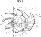
- FIG. 2 is an enlarged perspective view of the impeller 7 used in the present embodiment.
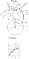
- FIG. 3A is a plan view showing that one blade 5 is mounted onto the hub 6, and
- FIG. 3B is a schematic view explaining that a base portion 5A of one blade 5 is mounted onto the peripheral wall portion 6A of the hub 6.
- FIGs. 4A to 4D are cross-sectional views respectively taken along lines A-A, B-B, C-C, and D-D of FIG. 2 .
- the seven blades 5 are integrally fixed to an outer wall of the peripheral wall portion 6A of the hub 6 at their base portions 5A.
- the seven blades 5 extend outwardly in a radial direction of the peripheral wall portion 6A from the outer wall of the peripheral wall portion 6A of the hub 6 and are disposed at an interval in a circumferential direction of the peripheral wall portion 6A.
- Each blade 5 has the following features.
- an imaginary line PL is assumed to pass one end 5Aa of the base portion 5A of the blade 5 positioned on the rear end side of the rotary shaft 8 and extending in parallel to the axial line X of the rotary shaft 8 along the outer peripheral surface of the peripheral wall portion 6A.
- the base portion 5A of the blade 5 is inclined in a direction from one end 5Aa of the base portion 5A to the other end 5Ab of the base portion 5A so as to be gradually away from the imaginary line PL in the rotation direction RD of the impeller 7, and curved so as to be convex in a direction opposite to the rotation direction RD.
- the blades 5 are fixed to the hub 6 in such a manner that the blades 5 are inclined along the peripheral wall portion 6A of the hub 6 such that the one end 5Aa of the base portion 5A is positioned in the vicinity of an opening portion of the peripheral wall portion 6A of the hub 6 as shown in FIG. 4D and the other end 5Ab of the base portion 5A is positioned more forward in the rotation direction RD than the one end 5Aa and is positioned opposite to the opening portion of the peripheral wall portion 6A as shown in FIG. 3 and FIG. 4A .
- Each blade 5 used in the present embodiment has a curved portion 4 as shown in FIGs. 4B to 4D .
- the curved portion 4 is formed in the vicinity of a radially outer end portion 5B positioned opposite to the base portion 5A in the radial direction of the peripheral wall portion 6A of the hub 6.
- the curved portion 4 is convex in the rotation direction RD, and is concave in the direction opposite to the rotation direction RD, and extends along the radially outer end portion 5B of the blade 5. More specifically, as shown in FIG.
- the curved portion 4 extends along the radially outer end portion 5B from a rear end edge 5C of the blade 5 positioned on a side where the one end 5Aa of the base portion 5A of the blade 5 is positioned and extending in the radial direction of the hub 6 to the vicinity of a front end edge 5D of the blade 5 positioned on a side where the other end 5Ab of the base portion 5A of the blade 5 is positioned and extending in the radial direction of the hub 6.
- the shape of the blade 5 is defined such that outer surface portions 5Ea and 5Eb positioned on both sides of the curved portion 4 in the radial direction exist in the same curved surface, in other words, the outer surface portion 5Eb exists on an extended surface of the outer surface portion 5Ea as viewed from the rear end edge 5C side.
- an outline of the rear end edge 5C of the blade 5 is curved to be convex in the rotation direction RD at a position corresponding to the curved portion 4.
- a dotted line 5C' in FIG. 3A denotes the outline of the rear end edge 5C when the curved portion 4 is not formed.
- the outline of the rear end edge 5C of the blade 5 is curved in an elongated S-shape.
- the width W of the curved portion 4 and the depth D of a concave portion 4A formed in the curved portion 4 as measured in the radial direction are determined so as to gradually decrease from the rear end edge 5C toward the front end edge 5D.
- the curved portion 4 be formed such that the deepest point of the concave portion 4A is positioned within a range from 0.8R to 0.95R.
- the locus of the deepest point of the concave portion 4A is denoted by a dotted line T.
- the maximum value for the width W of the curved portion 4 be in a range from 0.15R to 0.20R. If the maximum value for the width W of the curved portion 4 is less than 0.15R, the air volume is reduced to cause an increase in the amount of dropping at the inflection point of the air volume - static pressure characteristics as a whole, leading to an increase of noise. If the maximum value for the width W of the curved portion 4 is more than 0.20R, the inflection point of the air volume-static pressure characteristics decreases as a whole, leading to an increase of noise. Further, it is preferable that the maximum value for the depth D of the concave portion 4A of the curved portion 4 be in a range from 0.02R to 0.05R.
- the maximum value for the depth D of the concave portion 4A of the curved portion 4 is less than 0.02R, the air volume is reduced to cause an increase in the amount of dropping at the inflection point of the air volume - static pressure characteristics, leading to an increase of noise. If the maximum value for the depth D of the concave portion 4A of the curved portion 4 is more than 0.05R, the inflection point of the air volume - static pressure characteristics decreases as a whole, leading to an increase of noise.
- the length L of the curved portion 4 as measured in the circumferential direction of the peripheral wall portion 6A of the hub 6 be in a range from 2 ⁇ R/(2.8N) to 2 ⁇ R/(1.5N). If the length L of the curved portion 4 as measured in the circumferential direction is less than 2 ⁇ R/(2.8N), the air volume is reduced to cause an increase in the amount of dropping at the inflection point of the air volume-static pressure characteristics, leading to an increase of noise. If the length L of the curved portion 4 as measured in the circumferential direction is more than 2 ⁇ R/(1.5N), the inflection point of the air volume - static pressure characteristics decreases, leading to an increase of noise.
- FIG. 5 is a perspective view of an impeller used in an axial flow fan according to a first comparative example
- FIGS. 6A and 6B are cross-sectional views respectively taken along lines A-A and B-B of FIG. 5 .
- the impeller of the axial flow fan according to the first comparative example has a configuration in which a curved portion 4' is formed over the entire length of a blade 5', from a rear end edge 5'C of the blade 5' to front end edge 5'D thereof.
- FIG. 7 is a perspective view of an impeller used in an axial flow fan according to a second comparative example
- FIGS. 8A and 8B are cross-sectional views respectively taken along lines A-A and B-B of FIG. 7 .
- the impeller of the axial flow fan according to the comparative example 2 does not have the curved portion.
- the radius R of the impellers of the axial flow fans used in the test was 43 mm, and rotation speed thereof was 4,400 [min -1 ].
- the deepest point of the concave portion 4A of the curved portion 4 was set at a position of 0.9R assuming that the outer diameter of the impeller 7 is R.
- the length L of the curved portion 4 was set to 2 ⁇ R/(1.5N)
- the width W of the curved portion 4 was set to 0.19R
- the maximum value for the depth D of the concave portion 4A was set to 0.03R.
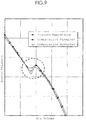
- FIG. 9 shows the air volume - static pressure characteristics of the axial flow fans according to the present embodiment and the first and second comparative examples under the above conditions.
- a region surrounded by a dotted line in FIG. 9 is the operating range in which the inflection point appears.
- the inflection point point at which the polarity of a variation of characteristics changes
- the amount of dropping (decrease in the characteristics) at the inflection point in the axial flow fan according to the present embodiment is smaller than that in any of the axial flow fans according to the first and second comparative examples.
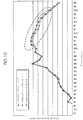
- FIG. 10 shows a relationship between the sound pressure level and frequency component in the axial flow fans according to the present embodiment and the first and second comparative examples measured under the same environment.
- the noise in the fan is mainly constituted by so-called turbulence noise. This noise is caused by a comparatively high frequency component (range surrounded by a dotted line in FIG. 10 : 1.2 kHz to 16 kHz).
- the sound pressure level of a frequency component which is a generation source of the noise is reduced in the axial flow fan according to the present embodiment as compared to that in any of the axial flow fans according to the first and second comparative examples.
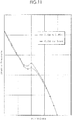
- FIG. 11 shows average air volume - static pressure characteristics when the deepest point of the concave portion 4A of the curved portion 4 exists in a proper range from 0.8R to 0.95R and the deepest point of the concave portion 4A exists at a position corresponding to less than 0.8R, assuming that the outer diameter of the impeller 7 is R. If the deepest point of the concave portion 4A exists at a position corresponding to more than 0.95R, the characteristics change in the same manner as with when the deepest point of the concave portion 4A exists at a position corresponding to less than 0.8R, In FIG.
- the length L of the curved portion 4 was set to 2 ⁇ R/(1,5N), the width W of the curved portion 4 was set to 0.19R, and the maximum value for the depth D of the concave portion 4A was set to 0.03R.
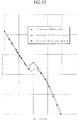
- FIG. 12 is a graph showing, together with the above-mentioned air volume - static pressure characteristics of the present embodiment, air volume - static pressure characteristics obtained when the position of the curved portion 4 was set to a position corresponding to 0.9R, the length of the curved portion 4 was set to 2 ⁇ R/(1.4N), the width W of the curved portion 4 was set to 0.21R, and the maximum value for the depth D of the concave portion 4A was set to 0.051R was defined as "curved portion - large" and when the position of the curved portion 4 was set to a position corresponding to 0.9R, the length of the curved portion 4 was set to 2nR/(2.9N), the width W of the curved portion 4 was set to 0.14R, and the maximum value for the depth D of the concave portion 4A was set to 0.019R was defined as "curved portion - small”.
Description
- The present invention relates to an axial flow fan.
- Japanese Utility Model Registration No.
3089140 U.S. Patent Application Publication No. 2003/0123988 ) discloses inFIGs. 1 to 3 an impeller of an axial flow fan in which a projecting edge 322 curved to form an included angle θ on the upper surface of a blade 32 is formed at a radially outer end portion thereof. - Japanese Utility Model Registration No.
3089140 U.S. Patent Application Publication No. 2003/0123988 ) describes that vortices 23 are generated at theradially end portion 13 of the blade as shown inFIG. 5 of the publication if the projecting edge 322 is not formed. Further, the publication describes that the vortex 23 leads to a reduction of static pressure, reduction of air volume, and increase of noise. Furthermore, the publication describes that the formation of the projecting edge 322 allows the static pressure to be increased, air volume to be increased, and noise to be reduced, as compared to when the projection edge 322 is not formed. The inventor of the present invention has confirmed that the effects described in the publication may be obtained. However, from the practical point of view, the amount of dropping at the inflection point appearing in static pressure - air volume characteristics cannot be reduced with a conventional configuration.
JP2000 192898A JPH08 177792A claim 1. - An object of the present invention is to provide an axial flow fan in which an amount of dropping at the inflection point appearing in air volume - static pressure characteristics may be reduced and noise may also be reduced as compared to conventional axial flow fans.
- In accordance with the present invention there is provided an axial flow fan having the characterizing features of
claim 1. - With the above configuration, it is possible to reduce the amount of dropping at the inflection point appearing in air volume - static pressure characteristics and reduce noise as compared to a conventional axial flow fan in which a projecting edge is formed over the entire length of the radially outer end portion of the blade. The effect obtained in the present invention were confirmed by experiments.
- In other words, with this arrangement one outer surface portion positioned on one side of the curved portion exist on an extended surface of the other outer surface portion. By defining the shape of the curved portion in this manner, it is possible to increase the inflection point appearing in air volume - static pressure characteristics and reduce noise as compared to the conventional axial flow fan in which a projecting edge is formed.
- It is preferable that, as the impeller is viewed from the front end portion of the rotary shaft toward the rear end portion thereof, an outline of the rear end edge of the blade be curved to be convex in the rotation direction at a position corresponding to the curved portion. By defining the shape in this manner, it is possible to reduce the amount of dropping at the inflection point appearing in air volume - static pressure characteristics and reduce noise.
- Assuming that the outer diameter of the impeller is R, it is preferable that the deepest point of the concave portion be positioned within a range from 0.8R to 0.95R. When the deepest point of the concave portion exists at a position closer to the base portion relative to the radial position corresponding to 0.8R, the inflection point of the air volume - static pressure characteristics decreases.
- Assuming that the number of blades is N, it is preferable that the length L of the curved portion as measured in the circumferential direction of the peripheral wall portion of the hub be in a range from 2πR/(2.8N) to 2πR/(1.5N). If the length L of the curved portion as measured in the circumferential direction is less than 2πR/(2.8N), the air volume is reduced to cause an increase in the amount of dropping at the inflection point of the air volume - static pressure characteristics. If the length L of the curved portion as measured in the circumferential direction is more than 2πR/(1.5N), the inflection point of the air volume - static pressure characteristics decreases as a whole, leading to an increase of noise.
- It is preferable that the maximum value for the width of the curved portion be in a range from 0.15R to 0.20R. If the maximum value for the width of the curved portion is less than 0.15R, the air volume is reduced to cause an increase in the amount of dropping at the inflection point of the air volume - static pressure characteristics, leading to an increase of noise. If the maximum value for the width of the curved portion is more than 0.20R, the inflection point of the air volume - static pressure characteristics decreases, leading to an increase of noise.
- Further, it is preferable that the maximum value for the depth D of the concave portion of the curved portion be in a range from 0.02R to 0.05R. If the maximum value for the depth D of the concave portion of the curved portion is less than 0.02R, the amount of dropping at the inflection point of the air volume - static pressure characteristics is increased to increase noise. If the maximum value for the depth D of the concave portion of the curved portion is more than 0.05R, the inflection point of the air volume - static pressure characteristics significantly decreases to increase noise. Specifically, the maximum value for the depth D of the curved portion may preferably be 1 to 2 mm.
- According to the present invention, it is possible to reduce the amount of dropping at the inflection point appearing in air volume - static pressure characteristics than in a conventional axial flow fan in which a projecting edge is formed over the entire length of the radially outer end portion of the blade, which further leads to a reduction in noise.
-
-
FIGs. 1A and 1B are respectively a front-side perspective view and a rear-side perspective view of an axial flow fan according to an embodiment of the present invention. -
FIG. 2 is an enlarged perspective view of an impeller used in the present embodiment. -
FIG. 3A is a plan view showing that one blade is mounted onto a hub, andFIG. 3B illustrates that a base portion of one blade is mounted onto the peripheral wall portion of the hub. -
FIGs. 4A to 4D are cross-sectional views respectively taken along lines A-A, B-B, C-C, and D-D ofFIG. 2 . -
FIG. 5 is a perspective view of an impeller used in an axial flow fan according to a first comparative example. -
FIGs. 6A and 6B are cross-sectional views respectively taken along lines A-A and B-B ofFIG. 5 . -
FIG. 7 is a perspective view of an impeller used in an axial flow fan according to a second comparative example. -
FIGs. 8A and 8B are cross-sectional views respectively taken along lines A-A and B-B ofFIG. 7 . -
FIG. 9 is a graph showing the air volume - static pressure characteristics of the axial flow fans according to the present embodiment and the first and second comparative examples. -
FIG. 10 is a graph showing a relationship between the sound pressure level and frequency component in the axial flow fans according to the present embodiment and the first and second comparative examples. -
FIG. 11 is a graph showing air volume - static pressure characteristics confirming a proper position range of the curved portion. -
FIG. 12 is a graph showing air volume - static pressure characteristics confirming a proper size range of the curved portion. - An embodiment of an axial flow fan according to the present invention will be described in detail hereinbelow with reference to the accompanying drawings.
FIGs. 1A and 1B are respectively a front-side perspective view and a rear-side perspective view of anaxial flow fan 1 according to an embodiment of the present invention. Theaxial flow fan 1 includes ahousing 3, animpeller 7 having sevenblades 5 which are disposed in thehousing 3 and rotating therein, and amotor 9 which drives and rotates theimpeller 7. Themotor 9 includes arotary shaft 8, as indicated with a dot line, having a front end portion and a rear end portion. Theimpeller 7 is fixed to the front end portion of therotary shaft 8. Amotor case 10 is fixed to thehousing 3 throughwebs 11. Thehousing 3 has a suction-side flange 13 of an annular shape at one side in an extending direction of the axial line (axial direction) of therotary shaft 8 and a discharge-side flange 15 of an annular shape at the other side in the extending direction of the axial line. Thehousing 3 also includes acylindrical portion 17 between theflanges 13 and 15. Anair channel 19 is formed by internal spaces of the suction-side flange 13, the discharge-side flange 15, and thecylindrical portion 17. Theimpeller 7 is rotated in theair channel 19. Theimpeller 7 includes ahub 6 having an annularperipheral wall portion 6A and sevenblades 5. A plurality of permanent magnets constituting a part of a rotor of themotor 9 are fixed to the inside of theperipheral wall portion 6A of thehub 6. -
FIG. 2 is an enlarged perspective view of theimpeller 7 used in the present embodiment.FIG. 3A is a plan view showing that oneblade 5 is mounted onto thehub 6, andFIG. 3B is a schematic view explaining that abase portion 5A of oneblade 5 is mounted onto theperipheral wall portion 6A of thehub 6.FIGs. 4A to 4D are cross-sectional views respectively taken along lines A-A, B-B, C-C, and D-D ofFIG. 2 . The sevenblades 5 are integrally fixed to an outer wall of theperipheral wall portion 6A of thehub 6 at theirbase portions 5A. The sevenblades 5 extend outwardly in a radial direction of theperipheral wall portion 6A from the outer wall of theperipheral wall portion 6A of thehub 6 and are disposed at an interval in a circumferential direction of theperipheral wall portion 6A. - Each
blade 5 has the following features. In order to identify the shape of theblade 5, an imaginary line PL is assumed to pass one end 5Aa of thebase portion 5A of theblade 5 positioned on the rear end side of therotary shaft 8 and extending in parallel to the axial line X of therotary shaft 8 along the outer peripheral surface of theperipheral wall portion 6A. As shown inFIG. 3B , thebase portion 5A of theblade 5 is inclined in a direction from one end 5Aa of thebase portion 5A to the other end 5Ab of thebase portion 5A so as to be gradually away from the imaginary line PL in the rotation direction RD of theimpeller 7, and curved so as to be convex in a direction opposite to the rotation direction RD. In other words, theblades 5 are fixed to thehub 6 in such a manner that theblades 5 are inclined along theperipheral wall portion 6A of thehub 6 such that the one end 5Aa of thebase portion 5A is positioned in the vicinity of an opening portion of theperipheral wall portion 6A of thehub 6 as shown inFIG. 4D and the other end 5Ab of thebase portion 5A is positioned more forward in the rotation direction RD than the one end 5Aa and is positioned opposite to the opening portion of theperipheral wall portion 6A as shown inFIG. 3 andFIG. 4A . - Each
blade 5 used in the present embodiment has acurved portion 4 as shown inFIGs. 4B to 4D . Thecurved portion 4 is formed in the vicinity of a radiallyouter end portion 5B positioned opposite to thebase portion 5A in the radial direction of theperipheral wall portion 6A of thehub 6. Thecurved portion 4 is convex in the rotation direction RD, and is concave in the direction opposite to the rotation direction RD, and extends along the radiallyouter end portion 5B of theblade 5. More specifically, as shown inFIG. 3 , thecurved portion 4 extends along the radiallyouter end portion 5B from arear end edge 5C of theblade 5 positioned on a side where the one end 5Aa of thebase portion 5A of theblade 5 is positioned and extending in the radial direction of thehub 6 to the vicinity of afront end edge 5D of theblade 5 positioned on a side where the other end 5Ab of thebase portion 5A of theblade 5 is positioned and extending in the radial direction of thehub 6. - Further, the shape of the
blade 5 is defined such that outer surface portions 5Ea and 5Eb positioned on both sides of thecurved portion 4 in the radial direction exist in the same curved surface, in other words, the outer surface portion 5Eb exists on an extended surface of the outer surface portion 5Ea as viewed from therear end edge 5C side. By defining the shape in this manner, it is possible to reduce the amount of dropping at the inflection point appearing in air volume - static pressure characteristics and reduce noise as compared to a conventional axial flow fan in which a projecting edge is formed. - When the
impeller 7 is viewed from the front end portion of therotary shaft 8 to the rear end portion thereof (i.e., as shown inFIG. 3A ), an outline of therear end edge 5C of theblade 5 is curved to be convex in the rotation direction RD at a position corresponding to thecurved portion 4. A dottedline 5C' inFIG. 3A denotes the outline of therear end edge 5C when thecurved portion 4 is not formed. InFIG. 3A , the outline of therear end edge 5C of theblade 5 is curved in an elongated S-shape. - As shown in
FIGs. 3 and4D , the width W of thecurved portion 4 and the depth D of aconcave portion 4A formed in thecurved portion 4 as measured in the radial direction are determined so as to gradually decrease from therear end edge 5C toward thefront end edge 5D. - As shown in
FIG. 3A , assuming that the outer diameter of theimpeller 7 is R, it is preferable that thecurved portion 4 be formed such that the deepest point of theconcave portion 4A is positioned within a range from 0.8R to 0.95R. InFIG. 3A , the locus of the deepest point of theconcave portion 4A is denoted by a dotted line T. When the deepest point of theconcave portion 4A exists at a position closer to thebase portion 5A relative to the radial position corresponding to 0.8R, the inflection point of the air volume - static pressure characteristics significantly decreases as a whole to increase noise. - It is preferable that the maximum value for the width W of the
curved portion 4 be in a range from 0.15R to 0.20R. If the maximum value for the width W of thecurved portion 4 is less than 0.15R, the air volume is reduced to cause an increase in the amount of dropping at the inflection point of the air volume - static pressure characteristics as a whole, leading to an increase of noise. If the maximum value for the width W of thecurved portion 4 is more than 0.20R, the inflection point of the air volume-static pressure characteristics decreases as a whole, leading to an increase of noise. Further, it is preferable that the maximum value for the depth D of theconcave portion 4A of thecurved portion 4 be in a range from 0.02R to 0.05R. If the maximum value for the depth D of theconcave portion 4A of thecurved portion 4 is less than 0.02R, the air volume is reduced to cause an increase in the amount of dropping at the inflection point of the air volume - static pressure characteristics, leading to an increase of noise. If the maximum value for the depth D of theconcave portion 4A of thecurved portion 4 is more than 0.05R, the inflection point of the air volume - static pressure characteristics decreases as a whole, leading to an increase of noise. - Assuming that the number of blades is N, it is preferable that the length L of the
curved portion 4 as measured in the circumferential direction of theperipheral wall portion 6A of thehub 6 be in a range from 2πR/(2.8N) to 2πR/(1.5N). If the length L of thecurved portion 4 as measured in the circumferential direction is less than 2πR/(2.8N), the air volume is reduced to cause an increase in the amount of dropping at the inflection point of the air volume-static pressure characteristics, leading to an increase of noise. If the length L of thecurved portion 4 as measured in the circumferential direction is more than 2πR/(1.5N), the inflection point of the air volume - static pressure characteristics decreases, leading to an increase of noise. - According to the present embodiment, it is possible to increase the static pressure and air volume in a practicable operating range as compared to a conventional axial flow fan in which a projection edge is formed in the entire radially outer end portion of the blade, thereby reducing noise.
- Next, results of a test for confirming meritorious effects of the axial flow fan according to the present embodiment will be described.
FIG. 5 is a perspective view of an impeller used in an axial flow fan according to a first comparative example, andFIGS. 6A and 6B are cross-sectional views respectively taken along lines A-A and B-B ofFIG. 5 . Unlike the impeller according to the present embodiment, the impeller of the axial flow fan according to the first comparative example has a configuration in which a curved portion 4' is formed over the entire length of a blade 5', from a rear end edge 5'C of the blade 5' tofront end edge 5'D thereof.FIG. 7 is a perspective view of an impeller used in an axial flow fan according to a second comparative example, andFIGS. 8A and 8B are cross-sectional views respectively taken along lines A-A and B-B ofFIG. 7 . Unlike the impeller according to the present embodiment, the impeller of the axial flow fan according to the comparative example 2 does not have the curved portion. - The radius R of the impellers of the axial flow fans used in the test was 43 mm, and rotation speed thereof was 4,400 [min-1]. In the axial flow fan according to the present embodiment, the deepest point of the
concave portion 4A of thecurved portion 4 was set at a position of 0.9R assuming that the outer diameter of theimpeller 7 is R. Further, the length L of thecurved portion 4 was set to 2πR/(1.5N), the width W of thecurved portion 4 was set to 0.19R, and the maximum value for the depth D of theconcave portion 4A was set to 0.03R.FIG. 9 shows the air volume - static pressure characteristics of the axial flow fans according to the present embodiment and the first and second comparative examples under the above conditions. A region surrounded by a dotted line inFIG. 9 is the operating range in which the inflection point appears. In this operating range, the inflection point (point at which the polarity of a variation of characteristics changes) appears. The larger the amount of dropping (decrease in the characteristics) at the inflection point is, the worse the cooling performance of the fan becomes. As can be seen formFIG. 9 , the amount of dropping (decrease in the characteristics) at the inflection point in the axial flow fan according to the present embodiment is smaller than that in any of the axial flow fans according to the first and second comparative examples. -
FIG. 10 shows a relationship between the sound pressure level and frequency component in the axial flow fans according to the present embodiment and the first and second comparative examples measured under the same environment. The noise in the fan is mainly constituted by so-called turbulence noise. This noise is caused by a comparatively high frequency component (range surrounded by a dotted line inFIG. 10 : 1.2 kHz to 16 kHz). As can be seen fromFIG. 10 , the sound pressure level of a frequency component which is a generation source of the noise is reduced in the axial flow fan according to the present embodiment as compared to that in any of the axial flow fans according to the first and second comparative examples. - As can be seen from the results shown in
FIGs. 9 and10 , when the curved portion having a predetermined shape is partially formed in the vicinity of the radially outer end portion of the blade as with the axial flow fan according to the present embodiment, it is possible to increase the air volume more than when the curved portion is formed over the entire length of the blade along the radially outer end portion of the blade to increase the inflection point of the air volume - static pressure characteristics, thereby improving the characteristics. In addition, noise may be reduced. Table 1 shown below compares the test results in terms of a relative ratio.[Table 1] Rotation speed Maximum air volume maximum static pressure Sound pressure level Present embodiment N 1.02Q P S-1 Second comparative example N Q P S First comparative example N Q 0.97P S+1 -
FIG. 11 shows average air volume - static pressure characteristics when the deepest point of theconcave portion 4A of thecurved portion 4 exists in a proper range from 0.8R to 0.95R and the deepest point of theconcave portion 4A exists at a position corresponding to less than 0.8R, assuming that the outer diameter of theimpeller 7 is R. If the deepest point of theconcave portion 4A exists at a position corresponding to more than 0.95R, the characteristics change in the same manner as with when the deepest point of theconcave portion 4A exists at a position corresponding to less than 0.8R, InFIG. 11 , the length L of thecurved portion 4 was set to 2πR/(1,5N), the width W of thecurved portion 4 was set to 0.19R, and the maximum value for the depth D of theconcave portion 4A was set to 0.03R. As can be seen fromFIG. 11 , it is preferable to set the position of thecurved portion 4 in the proper range in order to prevent the air volume - static pressure characteristics from being deteriorated. -
FIG. 12 is a graph showing, together with the above-mentioned air volume - static pressure characteristics of the present embodiment, air volume - static pressure characteristics obtained when the position of thecurved portion 4 was set to a position corresponding to 0.9R, the length of thecurved portion 4 was set to 2πR/(1.4N), the width W of thecurved portion 4 was set to 0.21R, and the maximum value for the depth D of theconcave portion 4A was set to 0.051R was defined as "curved portion - large" and when the position of thecurved portion 4 was set to a position corresponding to 0.9R, the length of thecurved portion 4 was set to 2nR/(2.9N), the width W of thecurved portion 4 was set to 0.14R, and the maximum value for the depth D of theconcave portion 4A was set to 0.019R was defined as "curved portion - small". As can be seen from the graph ofFIG. 12 , it is preferable to set the size of thecurved portion 4 in the above-mentioned proper range.
It has been confirmed by the tests that even though the number of blades, the outer diameter of the impeller, the rotation speed of the impeller, and the same number and shape of the webs are different, the same result is obtained.
While certain features of the invention have been described with reference to example embodiments, the description is not intended to be construed in a limiting sense. Various modifications of the example embodiments, as well as other embodiments of the invention, which are apparent to persons skilled in the art to which the invention pertains are deemed to lie within the scope of the invention.
Claims (7)
- An axial flow fan (1) comprising:an impeller (7) including a hub (6) having an annular peripheral wall portion (6A), and a plurality of blades (5) each having a base portion (5A) which is integrally fixed to an outer wall of the peripheral wall portion (6A) of the hub (6), extending from the outer wall of the peripheral wall portion (6A) outwardly in a radial direction of the peripheral wall portion (6A), and disposed at an interval in a circumferential direction of the peripheral wall portion (6A);a housing (3) having a cylindrical air channel (19) in which the impeller (7) rotates; anda motor (9) fixed to the housing (3) and including a rotary shaft (8) having a front end portion to which the impeller (7) is fixed and a rear end portion, wherein:assuming that an imaginary line (PL) passing one end (5Aa) of the base portion (5A) of the blade (5) positioned on the rear end portion side of the rotary shaft (8) and extending in parallel to an axial line (X) of the rotary shaft (8) and along an outer peripheral surface of the peripheral wall portion (6A), the base portion (5A) of the blade (5) is inclined in a direction from the one end (5Aa) of the base portion (5A) to the other end (5Ab) thereof so as to be gradually away from the imaginary line (PL) in a rotation direction (RD) of the impeller (7), and is curved so as to be convex in a direction opposite to the rotation direction (RD);each blade (5) has a curved portion (4) formed in the vicinity of a radially outer end portion (5B) positioned opposite to the base portion (5A) in the radial direction, the curved portion (4) being convex in the rotation direction (RD), being concave in the direction opposite to the rotation direction (RD);the curved portion (4) extends along the radially outer end portion (5B) from a rear end edge (5C) of the blade (5) to the vicinity of a front end edge (5D) of the blade (5), the rear end edge (5C) being positioned on a side where the one end (5Aa) of the base portion (5A) is positioned and extending in the radial direction, the front end edge (5D) of the blade (5) being positioned on a side where the other end (5Ab) of the base portion (5A) is positioned and extending in the radial direction;the width of the curved portion (4) as measured in the radial direction and the depth of a concave portion (4A) formed in the curved portion (4) are determined to gradually decrease in a direction from the rear end edge (5C) toward the front end edge (5D) of the blade (5), characterized in that:each blade has a first outer surface portion (5Eb) and a second outer surface portion (5Ea) that are positioned on both sides of the curved portion (4) in the radial direction such that said first outer surface portion (5Eb) is radially outside said curved portion (4) and said second outer surface portion (5Ea) is radially inside said curved portion (4); andsaid first and second outer surface portions (5Eb, 5Ea) are on a same curved surface that is convex in the direction opposite to the rotation direction (RD) such that said first outer surface portion (5Eb) exists on an extension of said second outer surface portion (5Ea) as viewed from the rear end edge (5C) side of the blade (5).
- The axial flow fan (1) according to claim 1, wherein
an outline of the rear end edge (5C) of the blade (5) is curved to be convex in the rotation direction (RD) at a position corresponding to the curved portion (4) as the impeller (7) is viewed from the front end portion of the rotary shaft (8) toward the rear end portion thereof . - The axial flow fan (1) according to claim 1, wherein
assuming that the outer diameter of the impeller (7) is R, the curved portion (4) is formed such that the deepest point of the concave portion (4A) is positioned within a range from 0.8R to 0.95R. - The axial flow fan (1) according to claim 3, wherein
assuming that the number of blades (5) is N, the length L of the curved portion (4) as measured in the circumferential direction is in a range from 2πR/(2.8N) to 2πR/(1.5N). - The axial flow fan (1) according to claim 3 or 4, wherein
the maximum value for the width of the curved portion (4) is in a range from 0.15R to 0.20R. - The axial flow fan (1) according to claim 3 or 4, wherein
the maximum value for the depth D of the concave portion (4A) of the curved portion (4) is in a range from 0.02R to 0.05R. - The axial flow fan (1) according to claim 3, wherein
the maximum value for the depth D of the concave portion (4A) is 1 mm to 2 mm.
Applications Claiming Priority (1)
| Application Number | Priority Date | Filing Date | Title |
|---|---|---|---|
| JP2008326283A JP5210852B2 (en) | 2008-12-22 | 2008-12-22 | Axial blower |
Publications (3)
| Publication Number | Publication Date |
|---|---|
| EP2199620A2 EP2199620A2 (en) | 2010-06-23 |
| EP2199620A3 EP2199620A3 (en) | 2017-02-22 |
| EP2199620B1 true EP2199620B1 (en) | 2019-01-09 |
Family
ID=41665264
Family Applications (1)
| Application Number | Title | Priority Date | Filing Date |
|---|---|---|---|
| EP09180201.7A Active EP2199620B1 (en) | 2008-12-22 | 2009-12-21 | Axial flow fan |
Country Status (5)
| Country | Link |
|---|---|
| US (1) | US8770943B2 (en) |
| EP (1) | EP2199620B1 (en) |
| JP (1) | JP5210852B2 (en) |
| CN (1) | CN101761493B (en) |
| TW (1) | TWI484104B (en) |
Families Citing this family (14)
| Publication number | Priority date | Publication date | Assignee | Title |
|---|---|---|---|---|
| JP5147784B2 (en) * | 2009-06-01 | 2013-02-20 | 三菱電機株式会社 | Fan and axial blower |
| CN104314868B (en) * | 2012-04-10 | 2017-07-14 | 夏普株式会社 | Propeller type fan, fluid delivery system, electric fan and molding die |
| CN104145118B (en) | 2012-04-10 | 2016-08-24 | 夏普株式会社 | Propeller fan, fluid delivery system and molding die |
| JP5705945B1 (en) * | 2013-10-28 | 2015-04-22 | ミネベア株式会社 | Centrifugal fan |
| USD732655S1 (en) * | 2013-11-21 | 2015-06-23 | Sanyo Denki Co., Ltd. | Fan |
| JP6141247B2 (en) * | 2014-10-03 | 2017-06-07 | シャープ株式会社 | Propeller fan, fluid feeder and mold |
| JP5905985B1 (en) | 2015-08-18 | 2016-04-20 | 山洋電気株式会社 | Axial flow fan and serial type axial flow fan |
| JP6430024B2 (en) | 2015-09-08 | 2018-11-28 | 三菱電機株式会社 | Outdoor unit for propeller fan, propeller fan device and air conditioner |
| US10859095B2 (en) | 2016-06-16 | 2020-12-08 | Mitsubishi Electric Corporation | Impeller and axial flow fan |
| JP6849366B2 (en) * | 2016-09-29 | 2021-03-24 | 山洋電気株式会社 | Reversible flow fan |
| CN108506247A (en) * | 2018-05-09 | 2018-09-07 | 约克广州空调冷冻设备有限公司 | Blade and use its axial wheel |
| WO2019214632A1 (en) * | 2018-05-09 | 2019-11-14 | 约克广州空调冷冻设备有限公司 | Blade and axial flow impeller using same |
| WO2020077802A1 (en) * | 2018-10-15 | 2020-04-23 | 广东美的白色家电技术创新中心有限公司 | Contra-rotating fan |
| JP7289235B2 (en) * | 2019-07-18 | 2023-06-09 | 株式会社コロナ | Propeller fan for outdoor unit of air conditioner |
Family Cites Families (19)
| Publication number | Priority date | Publication date | Assignee | Title |
|---|---|---|---|---|
| JPH0389140A (en) | 1989-08-31 | 1991-04-15 | Shimadzu Corp | Preparation of test piece for mooney test |
| US4930990A (en) * | 1989-09-15 | 1990-06-05 | Siemens-Bendix Automotive Electronics Limited | Quiet clutch fan blade |
| DE4020952A1 (en) * | 1990-06-30 | 1992-01-02 | Bosch Gmbh Robert | Rotating fan with sickle-shaped blades - has each blade made with curved recess in leading edge near root |
| US5215441A (en) * | 1991-11-07 | 1993-06-01 | Carrier Corporation | Air conditioner with condensate slinging fan |
| JPH08177792A (en) * | 1994-10-25 | 1996-07-12 | Matsushita Seiko Co Ltd | Axial fan |
| JPH1144432A (en) * | 1997-07-24 | 1999-02-16 | Hitachi Ltd | Air conditioner |
| JP3524410B2 (en) * | 1998-12-25 | 2004-05-10 | シャープ株式会社 | Propeller fan |
| JP3960776B2 (en) * | 2001-11-09 | 2007-08-15 | 松下電器産業株式会社 | Blower impeller for air conditioning |
| TW585227U (en) | 2001-12-31 | 2004-04-21 | Asia Vital Components Co Ltd | Improved structure for fan blade |
| DE60313147T2 (en) * | 2002-02-28 | 2007-12-13 | Daikin Industries, Ltd. | FAN |
| JP3089140U (en) | 2002-04-08 | 2002-10-11 | 奇▲こう▼科技股▲ふん▼有限公司 | Fan blades |
| JP2005016457A (en) * | 2003-06-27 | 2005-01-20 | Matsushita Electric Ind Co Ltd | Blower and heat exchange unit equipped with blower |
| CN1590778A (en) * | 2003-08-25 | 2005-03-09 | 乐金电子(天津)电器有限公司 | Axial fan |
| JP2006002584A (en) * | 2004-06-15 | 2006-01-05 | Samsung Electronics Co Ltd | Propeller fan and air conditioner using the same |
| JP4308718B2 (en) * | 2004-06-15 | 2009-08-05 | 三星電子株式会社 | Centrifugal fan and air conditioner using the same |
| JP4501575B2 (en) * | 2004-07-26 | 2010-07-14 | 三菱電機株式会社 | Axial blower |
| JP4689262B2 (en) * | 2004-12-21 | 2011-05-25 | 東芝キヤリア株式会社 | Axial fan, outdoor unit of air conditioner |
| JP2006322378A (en) * | 2005-05-19 | 2006-11-30 | Matsushita Electric Ind Co Ltd | Blower impeller |
| JP2008051074A (en) * | 2006-08-28 | 2008-03-06 | Samsung Electronics Co Ltd | Propeller fan |
-
2008
- 2008-12-22 JP JP2008326283A patent/JP5210852B2/en active Active
-
2009
- 2009-12-21 TW TW098143918A patent/TWI484104B/en active
- 2009-12-21 EP EP09180201.7A patent/EP2199620B1/en active Active
- 2009-12-22 US US12/644,385 patent/US8770943B2/en active Active
- 2009-12-22 CN CN2009102622770A patent/CN101761493B/en active Active
Non-Patent Citations (1)
| Title |
|---|
| None * |
Also Published As
| Publication number | Publication date |
|---|---|
| JP2010144702A (en) | 2010-07-01 |
| TW201040398A (en) | 2010-11-16 |
| JP5210852B2 (en) | 2013-06-12 |
| US20100158677A1 (en) | 2010-06-24 |
| CN101761493B (en) | 2013-03-27 |
| EP2199620A3 (en) | 2017-02-22 |
| CN101761493A (en) | 2010-06-30 |
| US8770943B2 (en) | 2014-07-08 |
| TWI484104B (en) | 2015-05-11 |
| EP2199620A2 (en) | 2010-06-23 |
Similar Documents
| Publication | Publication Date | Title |
|---|---|---|
| EP2199620B1 (en) | Axial flow fan | |
| US7762769B2 (en) | Axial fan assembly | |
| US7244099B2 (en) | Multi-vane centrifugal fan | |
| EP3133292A1 (en) | Axial blower and series-type axial blower | |
| US20040136830A1 (en) | Fan | |
| US20080253897A1 (en) | Axial Flow Fan | |
| US20190226492A1 (en) | Serrated fan blade, axial fan, and centrifugal fan | |
| JP3919496B2 (en) | RADIATOR FAN AND ENGINE COOLING DEVICE USING THE SAME | |
| US20130084173A1 (en) | Centrifugal fan | |
| KR20020011915A (en) | Centrifugal multiblade blower | |
| JP4099458B2 (en) | Centrifugal fan including stator vanes | |
| JP2002188599A (en) | Blower | |
| JP2006322378A (en) | Blower impeller | |
| KR20030018460A (en) | Turbo fan | |
| JP5992778B2 (en) | Axial fan | |
| JP2003180051A (en) | Moving blade of totally-enclosed fan-cooled rotating electric machine | |
| JP2006200457A (en) | Blower | |
| KR100255771B1 (en) | Axial/ diagonal fan construction | |
| JP2002285996A (en) | Multi-blade blower fan | |
| JP2014043780A (en) | Serial type axial flow fan | |
| JPH08170599A (en) | Blower impeller | |
| JP2007100518A (en) | Axial fan | |
| CN1273748C (en) | Cross flow fan | |
| JP2000110788A (en) | Axial-flow fan | |
| CN115898948A (en) | Blade and axial flow fan using same |
Legal Events
| Date | Code | Title | Description |
|---|---|---|---|
| PUAI | Public reference made under article 153(3) epc to a published international application that has entered the european phase |
Free format text: ORIGINAL CODE: 0009012 |
|
| AK | Designated contracting states |
Kind code of ref document: A2 Designated state(s): AT BE BG CH CY CZ DE DK EE ES FI FR GB GR HR HU IE IS IT LI LT LU LV MC MK MT NL NO PL PT RO SE SI SK SM TR |
|
| AX | Request for extension of the european patent |
Extension state: AL BA RS |
|
| PUAL | Search report despatched |
Free format text: ORIGINAL CODE: 0009013 |
|
| AK | Designated contracting states |
Kind code of ref document: A3 Designated state(s): AT BE BG CH CY CZ DE DK EE ES FI FR GB GR HR HU IE IS IT LI LT LU LV MC MK MT NL NO PL PT RO SE SI SK SM TR |
|
| AX | Request for extension of the european patent |
Extension state: AL BA RS |
|
| RIC1 | Information provided on ipc code assigned before grant |
Ipc: F04D 29/38 20060101ALI20170118BHEP Ipc: F04D 25/06 20060101AFI20170118BHEP |
|
| STAA | Information on the status of an ep patent application or granted ep patent |
Free format text: STATUS: REQUEST FOR EXAMINATION WAS MADE |
|
| 17P | Request for examination filed |
Effective date: 20170815 |
|
| RBV | Designated contracting states (corrected) |
Designated state(s): AT BE BG CH CY CZ DE DK EE ES FI FR GB GR HR HU IE IS IT LI LT LU LV MC MK MT NL NO PL PT RO SE SI SK SM TR |
|
| GRAP | Despatch of communication of intention to grant a patent |
Free format text: ORIGINAL CODE: EPIDOSNIGR1 |
|
| STAA | Information on the status of an ep patent application or granted ep patent |
Free format text: STATUS: GRANT OF PATENT IS INTENDED |
|
| INTG | Intention to grant announced |
Effective date: 20180726 |
|
| RIN1 | Information on inventor provided before grant (corrected) |
Inventor name: ISHIHARA, KATSUMICHI |
|
| GRAS | Grant fee paid |
Free format text: ORIGINAL CODE: EPIDOSNIGR3 |
|
| GRAA | (expected) grant |
Free format text: ORIGINAL CODE: 0009210 |
|
| STAA | Information on the status of an ep patent application or granted ep patent |
Free format text: STATUS: THE PATENT HAS BEEN GRANTED |
|
| AK | Designated contracting states |
Kind code of ref document: B1 Designated state(s): AT BE BG CH CY CZ DE DK EE ES FI FR GB GR HR HU IE IS IT LI LT LU LV MC MK MT NL NO PL PT RO SE SI SK SM TR |
|
| REG | Reference to a national code |
Ref country code: GB Ref legal event code: FG4D |
|
| REG | Reference to a national code |
Ref country code: CH Ref legal event code: EP Ref country code: AT Ref legal event code: REF Ref document number: 1087652 Country of ref document: AT Kind code of ref document: T Effective date: 20190115 |
|
| REG | Reference to a national code |
Ref country code: DE Ref legal event code: R096 Ref document number: 602009056604 Country of ref document: DE |
|
| REG | Reference to a national code |
Ref country code: IE Ref legal event code: FG4D |
|
| REG | Reference to a national code |
Ref country code: NL Ref legal event code: MP Effective date: 20190109 |
|
| REG | Reference to a national code |
Ref country code: LT Ref legal event code: MG4D |
|
| PG25 | Lapsed in a contracting state [announced via postgrant information from national office to epo] |
Ref country code: NL Free format text: LAPSE BECAUSE OF FAILURE TO SUBMIT A TRANSLATION OF THE DESCRIPTION OR TO PAY THE FEE WITHIN THE PRESCRIBED TIME-LIMIT Effective date: 20190109 |
|
| REG | Reference to a national code |
Ref country code: AT Ref legal event code: MK05 Ref document number: 1087652 Country of ref document: AT Kind code of ref document: T Effective date: 20190109 |
|
| PG25 | Lapsed in a contracting state [announced via postgrant information from national office to epo] |
Ref country code: PL Free format text: LAPSE BECAUSE OF FAILURE TO SUBMIT A TRANSLATION OF THE DESCRIPTION OR TO PAY THE FEE WITHIN THE PRESCRIBED TIME-LIMIT Effective date: 20190109 Ref country code: LT Free format text: LAPSE BECAUSE OF FAILURE TO SUBMIT A TRANSLATION OF THE DESCRIPTION OR TO PAY THE FEE WITHIN THE PRESCRIBED TIME-LIMIT Effective date: 20190109 Ref country code: NO Free format text: LAPSE BECAUSE OF FAILURE TO SUBMIT A TRANSLATION OF THE DESCRIPTION OR TO PAY THE FEE WITHIN THE PRESCRIBED TIME-LIMIT Effective date: 20190409 Ref country code: SE Free format text: LAPSE BECAUSE OF FAILURE TO SUBMIT A TRANSLATION OF THE DESCRIPTION OR TO PAY THE FEE WITHIN THE PRESCRIBED TIME-LIMIT Effective date: 20190109 Ref country code: ES Free format text: LAPSE BECAUSE OF FAILURE TO SUBMIT A TRANSLATION OF THE DESCRIPTION OR TO PAY THE FEE WITHIN THE PRESCRIBED TIME-LIMIT Effective date: 20190109 Ref country code: PT Free format text: LAPSE BECAUSE OF FAILURE TO SUBMIT A TRANSLATION OF THE DESCRIPTION OR TO PAY THE FEE WITHIN THE PRESCRIBED TIME-LIMIT Effective date: 20190509 |
|
| PG25 | Lapsed in a contracting state [announced via postgrant information from national office to epo] |
Ref country code: GR Free format text: LAPSE BECAUSE OF FAILURE TO SUBMIT A TRANSLATION OF THE DESCRIPTION OR TO PAY THE FEE WITHIN THE PRESCRIBED TIME-LIMIT Effective date: 20190410 Ref country code: BG Free format text: LAPSE BECAUSE OF FAILURE TO SUBMIT A TRANSLATION OF THE DESCRIPTION OR TO PAY THE FEE WITHIN THE PRESCRIBED TIME-LIMIT Effective date: 20190409 Ref country code: IS Free format text: LAPSE BECAUSE OF FAILURE TO SUBMIT A TRANSLATION OF THE DESCRIPTION OR TO PAY THE FEE WITHIN THE PRESCRIBED TIME-LIMIT Effective date: 20190509 Ref country code: LV Free format text: LAPSE BECAUSE OF FAILURE TO SUBMIT A TRANSLATION OF THE DESCRIPTION OR TO PAY THE FEE WITHIN THE PRESCRIBED TIME-LIMIT Effective date: 20190109 Ref country code: HR Free format text: LAPSE BECAUSE OF FAILURE TO SUBMIT A TRANSLATION OF THE DESCRIPTION OR TO PAY THE FEE WITHIN THE PRESCRIBED TIME-LIMIT Effective date: 20190109 |
|
| REG | Reference to a national code |
Ref country code: DE Ref legal event code: R097 Ref document number: 602009056604 Country of ref document: DE |
|
| PG25 | Lapsed in a contracting state [announced via postgrant information from national office to epo] |
Ref country code: AT Free format text: LAPSE BECAUSE OF FAILURE TO SUBMIT A TRANSLATION OF THE DESCRIPTION OR TO PAY THE FEE WITHIN THE PRESCRIBED TIME-LIMIT Effective date: 20190109 Ref country code: DK Free format text: LAPSE BECAUSE OF FAILURE TO SUBMIT A TRANSLATION OF THE DESCRIPTION OR TO PAY THE FEE WITHIN THE PRESCRIBED TIME-LIMIT Effective date: 20190109 Ref country code: SK Free format text: LAPSE BECAUSE OF FAILURE TO SUBMIT A TRANSLATION OF THE DESCRIPTION OR TO PAY THE FEE WITHIN THE PRESCRIBED TIME-LIMIT Effective date: 20190109 Ref country code: IT Free format text: LAPSE BECAUSE OF FAILURE TO SUBMIT A TRANSLATION OF THE DESCRIPTION OR TO PAY THE FEE WITHIN THE PRESCRIBED TIME-LIMIT Effective date: 20190109 Ref country code: CZ Free format text: LAPSE BECAUSE OF FAILURE TO SUBMIT A TRANSLATION OF THE DESCRIPTION OR TO PAY THE FEE WITHIN THE PRESCRIBED TIME-LIMIT Effective date: 20190109 Ref country code: EE Free format text: LAPSE BECAUSE OF FAILURE TO SUBMIT A TRANSLATION OF THE DESCRIPTION OR TO PAY THE FEE WITHIN THE PRESCRIBED TIME-LIMIT Effective date: 20190109 Ref country code: RO Free format text: LAPSE BECAUSE OF FAILURE TO SUBMIT A TRANSLATION OF THE DESCRIPTION OR TO PAY THE FEE WITHIN THE PRESCRIBED TIME-LIMIT Effective date: 20190109 |
|
| PLBE | No opposition filed within time limit |
Free format text: ORIGINAL CODE: 0009261 |
|
| STAA | Information on the status of an ep patent application or granted ep patent |
Free format text: STATUS: NO OPPOSITION FILED WITHIN TIME LIMIT |
|
| PG25 | Lapsed in a contracting state [announced via postgrant information from national office to epo] |
Ref country code: SM Free format text: LAPSE BECAUSE OF FAILURE TO SUBMIT A TRANSLATION OF THE DESCRIPTION OR TO PAY THE FEE WITHIN THE PRESCRIBED TIME-LIMIT Effective date: 20190109 |
|
| 26N | No opposition filed |
Effective date: 20191010 |
|
| PG25 | Lapsed in a contracting state [announced via postgrant information from national office to epo] |
Ref country code: SI Free format text: LAPSE BECAUSE OF FAILURE TO SUBMIT A TRANSLATION OF THE DESCRIPTION OR TO PAY THE FEE WITHIN THE PRESCRIBED TIME-LIMIT Effective date: 20190109 |
|
| PG25 | Lapsed in a contracting state [announced via postgrant information from national office to epo] |
Ref country code: TR Free format text: LAPSE BECAUSE OF FAILURE TO SUBMIT A TRANSLATION OF THE DESCRIPTION OR TO PAY THE FEE WITHIN THE PRESCRIBED TIME-LIMIT Effective date: 20190109 |
|
| REG | Reference to a national code |
Ref country code: CH Ref legal event code: PL |
|
| REG | Reference to a national code |
Ref country code: BE Ref legal event code: MM Effective date: 20191231 |
|
| PG25 | Lapsed in a contracting state [announced via postgrant information from national office to epo] |
Ref country code: MC Free format text: LAPSE BECAUSE OF FAILURE TO SUBMIT A TRANSLATION OF THE DESCRIPTION OR TO PAY THE FEE WITHIN THE PRESCRIBED TIME-LIMIT Effective date: 20190109 |
|
| PG25 | Lapsed in a contracting state [announced via postgrant information from national office to epo] |
Ref country code: LU Free format text: LAPSE BECAUSE OF NON-PAYMENT OF DUE FEES Effective date: 20191221 Ref country code: IE Free format text: LAPSE BECAUSE OF NON-PAYMENT OF DUE FEES Effective date: 20191221 |
|
| PG25 | Lapsed in a contracting state [announced via postgrant information from national office to epo] |
Ref country code: BE Free format text: LAPSE BECAUSE OF NON-PAYMENT OF DUE FEES Effective date: 20191231 Ref country code: LI Free format text: LAPSE BECAUSE OF NON-PAYMENT OF DUE FEES Effective date: 20191231 Ref country code: CH Free format text: LAPSE BECAUSE OF NON-PAYMENT OF DUE FEES Effective date: 20191231 |
|
| PG25 | Lapsed in a contracting state [announced via postgrant information from national office to epo] |
Ref country code: CY Free format text: LAPSE BECAUSE OF FAILURE TO SUBMIT A TRANSLATION OF THE DESCRIPTION OR TO PAY THE FEE WITHIN THE PRESCRIBED TIME-LIMIT Effective date: 20190109 |
|
| PG25 | Lapsed in a contracting state [announced via postgrant information from national office to epo] |
Ref country code: MT Free format text: LAPSE BECAUSE OF FAILURE TO SUBMIT A TRANSLATION OF THE DESCRIPTION OR TO PAY THE FEE WITHIN THE PRESCRIBED TIME-LIMIT Effective date: 20190109 Ref country code: HU Free format text: LAPSE BECAUSE OF FAILURE TO SUBMIT A TRANSLATION OF THE DESCRIPTION OR TO PAY THE FEE WITHIN THE PRESCRIBED TIME-LIMIT; INVALID AB INITIO Effective date: 20091221 |
|
| PG25 | Lapsed in a contracting state [announced via postgrant information from national office to epo] |
Ref country code: MK Free format text: LAPSE BECAUSE OF FAILURE TO SUBMIT A TRANSLATION OF THE DESCRIPTION OR TO PAY THE FEE WITHIN THE PRESCRIBED TIME-LIMIT Effective date: 20190109 |
|
| PGFP | Annual fee paid to national office [announced via postgrant information from national office to epo] |
Ref country code: GB Payment date: 20231220 Year of fee payment: 15 |
|
| PGFP | Annual fee paid to national office [announced via postgrant information from national office to epo] |
Ref country code: FR Payment date: 20231221 Year of fee payment: 15 Ref country code: FI Payment date: 20231220 Year of fee payment: 15 Ref country code: DE Payment date: 20231214 Year of fee payment: 15 |