EP2199092A1 - Printing apparatus - Google Patents
Printing apparatus Download PDFInfo
- Publication number
- EP2199092A1 EP2199092A1 EP09178539A EP09178539A EP2199092A1 EP 2199092 A1 EP2199092 A1 EP 2199092A1 EP 09178539 A EP09178539 A EP 09178539A EP 09178539 A EP09178539 A EP 09178539A EP 2199092 A1 EP2199092 A1 EP 2199092A1
- Authority
- EP
- European Patent Office
- Prior art keywords
- sheet
- sensor unit
- conveying
- roller
- rotary member
- Prior art date
- Legal status (The legal status is an assumption and is not a legal conclusion. Google has not performed a legal analysis and makes no representation as to the accuracy of the status listed.)
- Granted
Links
Images


Classifications
-
- B—PERFORMING OPERATIONS; TRANSPORTING
- B41—PRINTING; LINING MACHINES; TYPEWRITERS; STAMPS
- B41J—TYPEWRITERS; SELECTIVE PRINTING MECHANISMS, i.e. MECHANISMS PRINTING OTHERWISE THAN FROM A FORME; CORRECTION OF TYPOGRAPHICAL ERRORS
- B41J13/00—Devices or arrangements of selective printing mechanisms, e.g. ink-jet printers or thermal printers, specially adapted for supporting or handling copy material in short lengths, e.g. sheets
- B41J13/0009—Devices or arrangements of selective printing mechanisms, e.g. ink-jet printers or thermal printers, specially adapted for supporting or handling copy material in short lengths, e.g. sheets control of the transport of the copy material
-
- B—PERFORMING OPERATIONS; TRANSPORTING
- B41—PRINTING; LINING MACHINES; TYPEWRITERS; STAMPS
- B41J—TYPEWRITERS; SELECTIVE PRINTING MECHANISMS, i.e. MECHANISMS PRINTING OTHERWISE THAN FROM A FORME; CORRECTION OF TYPOGRAPHICAL ERRORS
- B41J13/00—Devices or arrangements of selective printing mechanisms, e.g. ink-jet printers or thermal printers, specially adapted for supporting or handling copy material in short lengths, e.g. sheets
- B41J13/02—Rollers
- B41J13/03—Rollers driven, e.g. feed rollers separate from platen
-
- B—PERFORMING OPERATIONS; TRANSPORTING
- B65—CONVEYING; PACKING; STORING; HANDLING THIN OR FILAMENTARY MATERIAL
- B65H—HANDLING THIN OR FILAMENTARY MATERIAL, e.g. SHEETS, WEBS, CABLES
- B65H5/00—Feeding articles separated from piles; Feeding articles to machines
- B65H5/06—Feeding articles separated from piles; Feeding articles to machines by rollers or balls, e.g. between rollers
- B65H5/062—Feeding articles separated from piles; Feeding articles to machines by rollers or balls, e.g. between rollers between rollers or balls
-
- B—PERFORMING OPERATIONS; TRANSPORTING
- B65—CONVEYING; PACKING; STORING; HANDLING THIN OR FILAMENTARY MATERIAL
- B65H—HANDLING THIN OR FILAMENTARY MATERIAL, e.g. SHEETS, WEBS, CABLES
- B65H7/00—Controlling article feeding, separating, pile-advancing, or associated apparatus, to take account of incorrect feeding, absence of articles, or presence of faulty articles
- B65H7/02—Controlling article feeding, separating, pile-advancing, or associated apparatus, to take account of incorrect feeding, absence of articles, or presence of faulty articles by feelers or detectors
- B65H7/14—Controlling article feeding, separating, pile-advancing, or associated apparatus, to take account of incorrect feeding, absence of articles, or presence of faulty articles by feelers or detectors by photoelectric feelers or detectors
-
- B—PERFORMING OPERATIONS; TRANSPORTING
- B65—CONVEYING; PACKING; STORING; HANDLING THIN OR FILAMENTARY MATERIAL
- B65H—HANDLING THIN OR FILAMENTARY MATERIAL, e.g. SHEETS, WEBS, CABLES
- B65H2511/00—Dimensions; Position; Numbers; Identification; Occurrences
- B65H2511/40—Identification
- B65H2511/416—Identification of material
-
- B—PERFORMING OPERATIONS; TRANSPORTING
- B65—CONVEYING; PACKING; STORING; HANDLING THIN OR FILAMENTARY MATERIAL
- B65H—HANDLING THIN OR FILAMENTARY MATERIAL, e.g. SHEETS, WEBS, CABLES
- B65H2513/00—Dynamic entities; Timing aspects
- B65H2513/40—Movement
-
- B—PERFORMING OPERATIONS; TRANSPORTING
- B65—CONVEYING; PACKING; STORING; HANDLING THIN OR FILAMENTARY MATERIAL
- B65H—HANDLING THIN OR FILAMENTARY MATERIAL, e.g. SHEETS, WEBS, CABLES
- B65H2553/00—Sensing or detecting means
- B65H2553/30—Sensing or detecting means using acoustic or ultrasonic elements
-
- B—PERFORMING OPERATIONS; TRANSPORTING
- B65—CONVEYING; PACKING; STORING; HANDLING THIN OR FILAMENTARY MATERIAL
- B65H—HANDLING THIN OR FILAMENTARY MATERIAL, e.g. SHEETS, WEBS, CABLES
- B65H2553/00—Sensing or detecting means
- B65H2553/40—Sensing or detecting means using optical, e.g. photographic, elements
- B65H2553/41—Photoelectric detectors
- B65H2553/414—Photoelectric detectors involving receptor receiving light reflected by a reflecting surface and emitted by a separate emitter
-
- B—PERFORMING OPERATIONS; TRANSPORTING
- B65—CONVEYING; PACKING; STORING; HANDLING THIN OR FILAMENTARY MATERIAL
- B65H—HANDLING THIN OR FILAMENTARY MATERIAL, e.g. SHEETS, WEBS, CABLES
- B65H2557/00—Means for control not provided for in groups B65H2551/00 - B65H2555/00
- B65H2557/60—Details of processes or procedures
- B65H2557/64—Details of processes or procedures for detecting type or properties of handled material
-
- B—PERFORMING OPERATIONS; TRANSPORTING
- B65—CONVEYING; PACKING; STORING; HANDLING THIN OR FILAMENTARY MATERIAL
- B65H—HANDLING THIN OR FILAMENTARY MATERIAL, e.g. SHEETS, WEBS, CABLES
- B65H2801/00—Application field
- B65H2801/03—Image reproduction devices
- B65H2801/12—Single-function printing machines, typically table-top machines
Abstract
Description
- The present invention relates to a printing apparatus which conveys a sheet and forms an image on the sheet.
- In order to realize formation of a high-grade image by a printing apparatus, a sheet-like printing medium (herein, simply referred to as a "sheet") is required to be conveyed with high accuracy.
- Recently, in order to improve accuracy in conveyance control, a direct sensor which performs direct detection of a movement amount of the sheet has been realized practically. The direct detection is conducted by imaging a surface of the sheet so as to perform image processing on the image of the sheet surface. For example,
U.S. Patent No. 7,104,710 discloses a technology for performing the conveyance control using the direct sensor. In an apparatus disclosed in the above-mentioned U.S. Patent, the direct sensor is provided on a carriage in which a print head is installed, or at a position which faces a surface of a discharge port of the print head. - In known structures, the direct sensor performs imaging only at a fixed position in a conveyance direction of the sheet. Therefore, during conveyance of the sheet, there disadvantageously exists a period during which sensing cannot be performed because the sheet is not located at a measurement position for the direct sensor (hereinafter, this period is referred to as "sensing disabled period"). For example, there is a case of performing image printing by a multipath method when printing is performed onto a trailing edge or a leading edge of the sheet. In such case, when the edge portion of the sheet deviates from the measurement position and the sensing is disabled, it is impossible to perform conveyance control with high accuracy by direct sensing. Therefore, there is a problem in that image quality at the edge portion of the sheet cannot be guaranteed.
- It is therefore desirable to provide a printing apparatus capable of reducing the sensing disabled period of the direct sensor.
According to the present invention, there is provided a printing apparatus as defined inclaims 1 to 15 and a conveying apparatus as defined in claim 16. - Further features of the present invention will become apparent from the following description of exemplary embodiments with reference to the attached drawings.
-
FIG. 1 is a perspective view illustrating an entire structure of a printing apparatus according to a first embodiment of the present invention. -
FIG. 2 is a cross-sectional view of the printing apparatus illustrated inFIG. 1 . -
FIG. 3 is a diagram illustrating a structure of a conveying mechanism. -
FIGS. 4A, 4B, 4C and 4D are diagrams illustrating conveyance of a sheet in time sequence. -
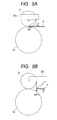
FIGS. 5A and 5B are enlarged views of a position at which measurement is performed by a direct-sensor unit. -
FIGS. 6A, 6B, 6C and 6D are diagrams illustrating conveyance of a sheet according to a second embodiment of the present invention in time sequence. -
FIGS. 7A, 7B, 7C and 7D are diagrams illustrating conveyance of a sheet according to a third embodiment of the present invention in time sequence. -
FIGS. 8A and 8B are diagrams illustrating conveyance of a sheet according to a fourth embodiment of the present invention in time sequence. -
FIG. 9 is a diagram illustrating a structure of the direct-sensor unit. -
FIGS. 10A, 10B and 10C are diagrams illustrating a principle of direct sensing. - Hereinafter, embodiments of the present invention are described with reference to the drawings. Note that constituent elements described in the embodiments are merely examples, and the scope of the present invention is not limited thereby.
- The present invention is applicable to various fields of movement detection as typified by a printing apparatus. In these fields, it is desirable to detect movement of a sheet-like object with high accuracy. Specifically, the present invention is applicable to an apparatus such as a printing apparatus and a scanner, and to an apparatus which conveys an object to perform various processes on the object such as inspection, reading, working, and marking in a processing unit, and which is used in an industrial field, a production field, a distribution field, and the like. In the case of applying the present invention to the printing apparatus, the present invention is applicable not only to a single-function printer, but also to a combined apparatus having a copying function, an image scanning function and so on, that is, a so-called multi-function printer. The present invention is applicable to a printer of various printing methods such as an ink-jet method, an electrophotographic method, and a thermal transfer method.
- Hereinafter, description is made of a first embodiment in which the present invention is applied to the ink-jet printing apparatus.
FIG. 1 andFIG. 2 are a perspective view and a cross-sectional view respectively, each illustrating an entire structure of the printing apparatus. Roughly speaking, the printing apparatus includes a sheet-supplying unit for supplying a sheet, a sheet-feeding unit for conveying and feeding the supplied sheet, a printing unit for forming an image on the sheet, and a sheet-ejecting unit for ejecting the sheet. The sheet-feeding unit and the sheet-ejecting unit constitute a conveying mechanism. - In the sheet-supplying unit, a
pressure plate 21 on which sheets (hereinafter, sometimes referred to as "print sheet(s)") P are stacked, a sheet-supplyingroller 28 for supplying the sheet P, aseparating roller 241 for separating the sheet P from other sheets, a returning lever for returning the sheet P to a stacked position, etc., are attached to abase 20 of the sheet-supplying unit. A sheet-supplying tray for retaining the stacked sheet P is attached to thebase 20 or to an outer covering of the sheet-supplying unit. Further, it is also possible to supply the sheet from adetachable cassette 881. - A description of the sheet-feeding unit constituting the conveying mechanism follows. A conveying roller 36 (hereinafter, sometimes referred to as "first conveying roller") is a rotary member positioned on an upstream side of a
print head 7 which will be described later. The conveyingroller 36 has a metal shaft whose surface is coated with microparticles of ceramic. Metal portions at both ends of theconveying roller 36 are supported by bearings attached to achassis 11. The conveyingroller 36 is provided withmultiple pinch rollers 37 and drives the pinch rollers in a contact manner. Each of thepinch rollers 37 is retained in a pinch-roller holder 30. Thepinch rollers 37 are biased by a pinch-roller spring 31, thereby to be brought into pressured contact with the conveyingroller 36. As a result, a conveying force between theconveying roller 36 and thepinch rollers 37 for the sheet P is generated. At an entrance of the sheet-feeding unit to which the sheet P is conveyed from the sheet-supplying unit, a paper-guide flapper 33 for guiding the sheet P and aplaten 34 are provided. Theplaten 34 is attached to thechassis 11 and fixed in position. Further, the pinch-roller holder 30 is provided with asensor lever 321 and a PE-sensor 32 (Paper End Sensor)). Thesensor lever 321 operates (i.e. moves) when a leading edge or a trailing edge of the sheet P passes thesensor lever 321, and thesensor 32 measures the operation (or movement) of thesensor lever 321. - The sheet P fed from the sheet-supplying unit to the sheet-feeding unit is guided by the pinch-
roller holder 30 and the paper-guide flapper 33, thereby to be fed between a pair of roller assemblies consisting of theconveying roller 36 comprising preferably a single roller and a pinch roller assembly 37 (which comprises an array of aligned pinch rollers in a preferred embodiment, but which may comprise a single cylinder). At this time, the leading edge of the sheet P is measured by thesensor lever 321, to thereby obtain a print position on the sheet P. Then, the sheet P is conveyed on theplaten 34 by rotation of theconveying roller 36 and thepinch rollers 37, the rotation being caused by a conveyingmotor 35. - The printing unit is described next. On a downstream side of the sheet-feeding unit in the conveyance direction of the
conveying roller 36, there is provided the printing unit including theprint head 7 for forming the image based on image information. Theprint head 7 is an ink-jet print head in whichink tanks 71 for respective colors are installed, theink tanks 71 being replaceable separately. In theprint head 7, by giving a discharging energy to the ink by a heater or a piezoelectric element, the ink is discharged from the nozzle. As a result, the image is formed on the sheet P. - At a position facing the nozzle of the
print head 7, theplaten 34 for supporting the sheet P is provided. Theplaten 34 is provided with aplaten absorber 344 for absorbing the ink overflowing from edges of the sheet P, for example when entire-surface printing (borderless printing) is performed. - The
print head 7 is attached to acarriage 50. Thecarriage 50 is supported by aguide shaft 52 and aguide rail 111. Theguide shaft 52 causes thecarriage 50 to perform reciprocal scanning in a direction orthogonal to the conveyance direction of the sheet P, and theguide rail 111 holds an end of thecarriage 50 and maintains a space between theprint head 7 and the sheet P. Note that in the illustrated embodiment, theguide shaft 52 is attached to thechassis 11, and theguide rail 111 is formed integrally with thechassis 11. - The
carriage 50 is driven, with an intermediary in the form of atiming belt 541, by acarriage motor 54 attached to thechassis 11. Thetiming belt 541 is stretched and supported by an idle (or idler)pulley 542. Acode strip 561 provided with markings at a pitch of 150 to 300 marks per inch (or approximately 60 to 120 marks per cm) for measuring the position of thecarriage 50 is provided parallel to thetiming belt 541. Further, an encoder sensor for reading thecode strip 561 is provided on a carriage substrate installed in thecarriage 50. The carriage substrate includes a contact for making electrical connection with theprint head 7, and aflexible cable 57 for transmitting a signal from acontroller 91 to theprint head 7. Thecontroller 91 is a control unit for performing various controls of the entire apparatus. The control unit includes a central processing unit (CPU), a memory, and various input/output (I/O) interfaces. - In the above-mentioned structure, when forming the image onto the sheet P, a roller assembly pair, that is, the conveying
roller 36 and the pinch roller(s) 37, conveys and stops the sheet P at the position at which the image is to be formed. Then, while thecarriage motor 54 causes thecarriage 50 to perform scanning, theprint head 7 discharges the ink toward the sheet P in response to the signal from thecontroller 91. A desired image is formed on the sheet P by alternately repeating the steps of conveying the sheet P by a predetermined amount using the roller assembly pair, and scanning of the carriage including discharge of the ink onto the sheet. - The sheet-ejecting unit constituting the conveying mechanism will now be described. The sheet-ejecting unit includes two sheet-ejecting rollers (hereinafter, sometimes referred to as "second conveying rollers") 40 to which rotary members are positioned downstream of the
print head 7. Further, the sheet-ejecting unit includesspurs 42 and a gear row. Thespurs 42 come into contact with the sheet-ejectingrollers 40 with a predetermined pressure, and are rotatable together with the sheet-ejectingrollers 40. The gear row transmits the driving force of the (first) conveyingroller 36 to the (second) sheet-ejectingrollers 40. The sheet P onto which the image is formed is nipped between the sheet-ejectingrollers 40 and thespurs 42, and conveyed and ejected by rotation of the sheet-ejectingrollers 40 and the rotation of thespurs 42 driven by the rotation of the sheet-ejectingrollers 40. - The apparatus according to this embodiment is capable of performing double-sided printing onto the sheet P. The sheet P passes between the conveying
roller 36 and thepinch rollers 37 and, at the same time, printing is performed by theprint head 7 on the surface of the sheet P. At the time of automatic double-sided printing, the sheet P which passes between the conveyingroller 36 and thepinch rollers 37 is fed back between the conveyingroller 36 and thepinch rollers 37 by the above-mentioned sheet-ejectingrollers 40 and thespurs 42. As a result, the trailing edge of the sheet P is nipped between the conveyingroller 36 and thepinch rollers 37 again, and conveyed in the reverse direction. The sheet P which is fed again is then nipped between a double-sided roller 891 and the double-sided pinch roller 892, and then conveyed using a guide. A sheet-conveyance path for double-sided printing joins a sheet-conveyance path for the above-mentioned U-turn conveyance. Therefore, the sheet-conveyance path thereafter is the same as the above in structure and effect. Then, printing is performed in a state in which a back surface (surface not subjected to printing) faces theprint head 7 to be printed upon (and may also be in a state in which the print sheet is reversed compared to the first printing direction). -
FIG. 3 is a schematic view of the conveying mechanism. For simplifying the description,FIG. 3 illustrates only one of the two conveyingrollers 40. The sheet P is nipped between the first conveyingroller 36 and thepinch rollers 37, and then conveyed. The first conveyingroller 36 is arranged on the further upstream side in the conveyance direction compared with theprint head 7, and thepinch rollers 37 which face the first conveyingroller 36 are pressed and driven thereby. The sheet P passes on theplaten 34 which is arranged so as to face theprint head 7 and in order to maintain the sheet P at a certain height relative to the print head. The sheet P is then fed to the downstream side. The sheet P is nipped between the second conveyingrollers 40 and thespurs 42, and conveyed to the sheet-ejecting unit. The second conveyingrollers 40 are positioned on the downstream side in the conveyance direction compared with theprint head 7, and thespurs 42 which face the second conveyingrollers 40 are pressed and driven thereby. The first conveyingroller 36 and the second conveyingrollers 40 receive the driving force from a conveyingmotor 35 through atransmission belt 39, a first-conveying-roller gear 361 pressed into the first conveyingroller 36, anidler gear 45, and a second-conveying-roller gear 404. - The sheet-feeding unit includes the
sensor lever 321 for measuring each of the leading edge and the trailing edge of the sheet P, and a direct-sensor unit 801 capable of accurately measuring the conveyance amount of the sheet P. The direct-sensor unit 801 serves as a sensor unit which optically detects the surface of the sheet P and measures the moving state of the sheet P. As will be described later, the direct-sensor unit 801 is capable of measuring not only the sheet but also the moving state of the surface of the rotating roller. -
FIG. 9 illustrates the structure of the direct-sensor unit 801. Thedirect sensor 801 includes alight source 811 and a light-receivingportion 812 for receiving light from thelight source 811 reflected from an object of observation (such as a sheet P). As an image sensor in the light-receivingportion 812, a charge coupled device (CCD) image sensor or a complementary metal oxide semiconductor (CMOS) image sensor is used. In a light path extending from thelight source 811 to the light-receivingportion 812, alens 813 is provided. Further, there is provided asignal processing section 814 for storing and processing image data obtained by a light-receiving element of the light-receivingportion 812. The signal processing for direct sensing may be performed by thecontroller 91 or by a separatesignal processing section 814. -
FIGS. 10A to 10C are diagrams illustrating a principle of the direct sensing.FIG. 10A illustrates image data obtained by imaging performed by one image sensor at a time T1.FIG. 10B illustrates image data obtained by imaging performed at a time T2, that is, when the sheet is slightly moved after the time T1. By a signal processing including a well-known pattern matching process, it is determined whether or not a pattern exists in the image data ofFIG. 10B that is the same as a pattern in a given region of the image data ofFIG. 10A exists in the image data ofFIG. 10B (though a cross pattern is used in this case, any pattern may be used in fact). As a result of the determination, it is possible to obtain a movement amount M of a medium based on a displacement amount (number of pixels) therebetween as illustrated inFIG. 10C . Further, by dividing the movement amount M by a period of time between the times T1 and T2, it is possible to obtain a moving speed of the sheet during the period of time. - In
FIG. 3 , the direct-sensor unit 801 is arranged at a position which faces the uppermost surface of the first conveyingroller 36 in the conveyance path of the sheet P, the position being that at which imaging is performed with respect to the surface of the sheet P. Paths of illuminated light and received light of the direct-sensor unit 801 are each indicated by an arrow. InFIG. 3 (diagram viewed in a sectional direction), although the direct-sensor unit 801 and thepinch rollers 37 seem, when viewed from along the axis of the pinch rollers, to overlap with each other, the direct-sensor unit 801 and thepinch rollers 37 may in fact be arranged in a positional relationship in which they are spaced apart along the axial direction. The pinch rollers may be a series of short cylinders that are respectively aligned in the axial direction. The direct-sensor unit 801 may be positioned between the aligned pinch rollers, in order to perform imaging by illuminating the surface of the conveying roller in a region between the separately arranged pinch rollers adjacent to each other. Alternatively, the direct-sensor unit 801 may be at a position further outside the outermost pinch roller, in order to perform imaging by illuminating the surface of the conveying roller outside of the contact area of the pinch rollers. - In the state in which the sheet P is nipped between the first conveying
roller 36 and thepinch rollers 37, the direct-sensor unit 801 images the surface of the sheet P, to thereby measure the sheet conveyance (i.e. movement) amount. On the other hand, in the case where the sheet P is not nipped between the first conveyingroller 36 and thepinch rollers 37, the direct-sensor unit 801 is capable of measuring the moving state of the surface of the roller by imaging the surface of the first conveyingroller 36. Based on the moving state of the surface of the first conveyingroller 36, the conveyance amount of the sheet P is estimated. The thus-obtained estimate value of the conveyance amount of the sheet P is more accurate than the estimate value of rotation of the rotary member obtained by the rotary encoder. This is because eccentricity with respect to the rotation axis or local lack of uniformity of the surface shape exists normally in the roller. It is impossible to detect those effects by the rotary encoder. However, by directly detecting the moving state of the surface of the roller by the direct sensor, it is possible to perceive the moving state including those effects. - The control unit is capable of recognizing, based on the image data obtained by the direct-
sensor unit 801, whether the current object of measurement is the sheet or the surface of the roller. The surface state may be significantly different between the surface of the sheet and the surface of the roller, and hence it is possible to recognize, using an image recognition process, which surface is being sensed. The control unit performs control by causing the direct sensor unit to make different corrections in measurement output between the case in which the sheet is the object of measurement and the case in which the roller is the object of measurement. -
FIGS. 4A to 4D are diagrams illustrating the conveyance of the sheet in a time sequence. The first conveyingroller 36 is used as the rotary member which can be measured by the direct-sensor unit 801. As described above, the direct-sensor unit 801 is arranged so as to face the conveyance path for the sheet P and the first conveyingroller 36 positioned on the upstream side of theprint head 7. -
FIG. 4A illustrates a state before the sheet P reaches the first conveyingroller 36. In this state, the direct-sensor unit 801 is incapable of directly measuring the sheet P, but is capable of measuring the surface of the first conveyingroller 36, and is thereby capable of accurately measuring the moving state of the surface of the first conveyingroller 36. Based on the moving state of the surface of the first conveyingroller 36 measured by the direct-sensor unit 801, it is possible to calculate the rotation amount of the first conveyingroller 36.
Therefore, by performing feedback control of the conveyingmotor 35, it is possible accurately to control the rotation amount of the first conveyingroller 36, and it is thus possible to control the moving state of the surface thereof (and the eventual speed of the sheet that will be conveyed by the rotating roller). Further, there is provided thesensor lever 321 which rotates when the sheet P is in contact therewith, and hence it is possible to measure the position of the leading edge of the sheet P by the PE sensor 32 (seeFIG. 2 ) for measuring the rotation operation of thesensor lever 321. From this measurement timing, it is possible to perform registration of the sheet P (i.e. parallel feeding registration of the first conveyingroller 36 and the sheet P), and it is also possible to use the timing as information for determining a starting time and thereby position for printing. - In
FIG. 4B , when the sheet P reaches an upper portion of the first conveyingroller 36, the sheet P appears directly below the direct-sensor unit 801. Therefore, the object of measurement by the direct-sensor unit 801 is switched from the surface of the first conveyingroller 36 to the sheet P. In this case, even when the object of measurement is switched, it is possible to maintain the feedback control of the conveyingmotor 35 based on the output information of the direct-sensor unit 801. When the sheet P is not located directly below the direct-sensor unit 801, the rotation amount of the first conveyingroller 36 is controlled. In contrast, when the sheet P is located directly below the direct-sensor unit 801, the conveyance amount of the sheet P is controlled. - From the state shown in
FIG. 4B to the state shown inFIG. 4C , the sheet P is nipped between the first conveyingroller 36 and thepinch rollers 37 and conveyed thereby. Therefore, the direct-sensor unit 801 is capable of directly measuring the conveyance amount of the sheet P. Based on the information obtained by this measurement, the conveyingmotor 35 is subjected to feedback control, and the sheet P is accurately conveyed to a predetermined position and stopped at the position. As a result, high quality printing can be performed by theprint head 7. - After that, as illustrated in
FIG. 4D , the sheet P gets out of the position at which the sheet P is nipped between the first conveyingroller 36 and thepinch rollers 37. As a result, the sheet P is nipped between the second conveyingrollers 40 and thespurs 42 which are positioned on the downstream side compared with theprint head 7, and is ready for conveyance. - In this state, the direct-
sensor unit 801 is not in the state of directly measuring the sheet P. However, the direct-sensor unit 801 accurately measures the moving state of the surface of the first conveyingroller 36 by direct sensing. Based on this measurement, the conveyance amount of the sheet is estimated. Further, based on the rotation amount of the first conveyingroller 36, the rotation amount of the second conveyingrollers 40 driven thereby is estimated. - After that, even after the completion of image formation, the direct-
sensor unit 801 continuously measures the moving state of the surface of the first conveyingroller 36. By performing the feedback control of the rotation amount of the first conveyingroller 36 by the conveyingmotor 35, ejecting operation of the sheet P can be performed. - Even when measurement of the sheet P is impossible, the direct-
sensor unit 801 measures the moving state of the surface of the first conveyingroller 36. Therefore, the direct-sensor unit 801 calculates the rotation amount, thereby continuously to perform the feedback control. It is previously known that there is a difference between the moving state of the first conveyingroller 36 and the moving state of the sheet P. Therefore, the rotation amount is controlled by correcting the measurement output so as to obtain the moving state of the surface of the first conveyingroller 36, the moving state enabling the sheet P to be conveyed by a desired conveyance amount. - Further, the conveyance amount of the sheet P sometimes changes depending on type (with a difference in thickness, rigidity, and coefficient of friction) of the sheet P. Therefore, according to the type of the sheet to be used, the measurement output by the direct-sensor unit is corrected, thereby to perform control. Specifically, according to the type of the sheet P, the moving state of the surface of the first conveying
roller 36 for obtaining the desired conveyance amount is determined in advance. Information on the type of the sheet P is received from a printer driver, a sensor for discriminating the types of the sheet, or the like. The measurement output is corrected so as to obtain the moving state of the surface of the first conveyingroller 36 according to the received information, and then the rotation amount of the first conveyingroller 36 is set. -
FIGS. 5A and 5B are enlarged views of a position at which detection is performed by the direct-sensor unit 801. As illustrated inFIG. 5A , in this embodiment, a vicinity of a position at which the sheet P comes into contact with the surface of the first conveyingroller 36 is set as a measurement position (imaging position) for the direct-sensor unit 801. That is, a nipping position on the first conveyingroller 36 at which thepinch rollers 37 come into contact therewith when viewed from a cross-sectional direction is set as the measurement position (imaging position) for the direct-sensor unit 801. Actually, it is impossible to perform imaging at the nipping position at which both the rollers are physically in contact with each other, because the pinch rollers physically obstruct imaging of the direct-sensor unit 801. Therefore, there is set as the measurement position a position which is on a line obtained by extending a line representing the nipping position (at which both the rollers are substantially in line-contact with each other because both rollers are cylindrical in shape and touch along a line). In other words, the sensor is positioned, as shown inFig. 5A , on a line parallel to the axes of the conveying and pinch rollers, such that the sensor is able to measure the surface of the conveyingroller 36, but further along this line than thepinch rollers 37 extend. For example, thesensor 801 may be positioned on the axis of thepinch rollers 37, but further along the axis to where the pinch rollers do not extend, but to where the conveying roller does (and thereby measures a surface of the conveying roller adjacent its end). Light from the conveyingroller 36 received by thesensor 801 for imaging is transmitted toward the sensor from a direction perpendicular to the sheet P (and perpendicular to the detecting surface of the sensor). The direction of conveyance of the sheet P may be considered to be a tangent line with respect to the circumference of the first conveyingroller 36 at the nipping position. When the imaging of the surface of the roller is performed from directly above the surface (i.e. in a direction of a perpendicular line from the surface), the surface of the roller, despite its cylindrical curved surface, can be regarded as substantially the same type of flat surface as the sheet P. Therefore, errors in measurement of the movement detection are reduced. A detection result of the sheet P is equal to a speed LP which is an actual speed of the sheet P, and a detection result of theroller 36 is equal to a circumferential speed RP which is an actual circumferential speed of theroller 36. As the nipping position between the rollers and the measurement position are substantially equal, the speed LP and the speed RP are equal. Note that the word "perpendicular" herein is a concept which is not strictly limited to 90° and includes a range of angles where the above-mentioned operations and effects can be realized. The above-mentioned operations and effects can be realized as long as the light reflected from the surface of the cylinder or sheet is within the imaging (i.e. receiving) surface of the image sensor included in thesensor 801. - If, as illustrated in
FIG. 5B , the direct-sensor unit 801 performs the measurement at a position shifted significantly (perpendicularly) from the nipping position, the sheet P is seen by the sensor as floating above the detected surface of the first conveyingroller 36. Therefore, the detected positions of the sheet P and the surface of the first conveyingroller 36 are different. Further, imaging of the surface of the first conveyingroller 36 is performed at an angle different from the perpendicular line as shown inFig. 5B , because of the non-parallel surface of the roller with respect to the sensor's light-receiving surface. As a result, a large difference occurs in detection results between the movement detection of the sheet P and the movement detection of the surface of the first conveyingroller 36. A detection result of the sheet P is the speed LP, however, a detection result of theroller 36 is smaller than the circumferential speed RP. As view from thesensor 801, a speed of theroller 36 in the conveyance direction of the sheet P becomes smaller than the circumferential speed RP, therefore the detection of theroller 36 is inaccurate. Further, in the image obtained by imaging the surface of the first conveyingroller 36, blurring occurs at one side, which disturbs accurate detection of movement. In the present embodiment, such inconveniences do not exist thanks to the sensor being parallel to and aligned with the axes of the rollers and thus being effectively above the nipping portion. Further, in this embodiment, imaging of the nipping portion is substantially performed. Therefore, it is possible accurately to determine whether or not the first conveyingroller 36 is nipping the sheet, and it is also possible to recognize accurately the feeding amount of the sheet at the time of registration. - The timing at which the sheet P emerges from the nipping position (as shown in
Fig. 4C ) between the first conveyingroller 36 and thepinch rollers 37 can be measured directly by the direct-sensor unit 801. In this way, the sensor obtains information regarding the emergence of the sheet from the nipping position, such as information regarding changes in behaviour of the sheet P, e.g. a small separation of the sheet P from theplaten 34. This information can be used to control the discharge of the ink. It is also possible to obtain information on a small shift in conveyance amount of the sheet P when the sheet P emerges from the nipping position and to feedback this information as a correction value such that the alignment or conveyance amount of the sheet may be corrected as the sheet P emerges from the nipping position. - It is possible to reduce the effects of the change in behaviour caused by the sheet P released from nipping by causing the direct-
sensor unit 801 to measure the sheet P at a time immediately after the sheet P emerges from the nipping position so as to directly measure the conveyance amount of the sheet P. When especially aiming at such effects, the region to be measured by the direct-sensor unit 801 does not necessarily correspond to the nipping position, and the region on the downstream side in the vicinity of the nipping position may be set as the region to be measured. - Hereinafter, it is described that the same determination as described above is possible even if the
sensor lever 321 and the PE sensor 32 (seeFIG. 2 ) are not provided. In this case, the first conveyingroller 36 has a structure in which a surface of a metal roller shaft is coated with alumina particles using a resin binder layer, and hence the first conveyingroller 36 is a roller having extremely high (rough) surface roughness. This extremely high surface roughness enables strong-grip conveyance of the sheet. Generally, the surface of the sheet P is flat and smooth compared with the surface of the first conveyingroller 36, and hence the images of the two surfaces obtained by imaging performed by the direct-sensor unit 801 are extremely different from each other. It is thus easy to discriminate the differences by image processing. By this discrimination, it is determined whether or not the sheet P exists directly below the direct-sensor unit 801. Furthermore, the leading edge of the sheet P may be measured based on the image obtained by imaging performed by the direct-sensor unit 801. Analysis of the image data by image processing enables the determination of whether or not the sheet P is conveyed directly below the direct-sensor unit 801. Similarly, it is also possible to measure the trailing edge of the sheet P so as to determine when the sheet P emerges from directly below the direct-sensor unit 801. - In the above-mentioned manner, the direct-
sensor unit 801 measures the state illustrated inFIG. 4B (and 4C ). That is, it is detected that the sheet P reaches the nipping position between the first conveyingroller 36 and thepinch rollers 37, which are opposite each other. After feeding out the sheet P by the predetermined amount, it is possible to perform the registration, which is effected by forming a loop of the sheet P by reverse rotation of the first conveyingroller 36 with the sheet-supplyingroller 28 being stopped. Further, since it is possible to measure the position of the leading edge of the print sheet P regardless of whether or not the registration is performed, it is also possible to determine the starting point for printing. - By arranging the direct-
sensor unit 801 so as to be opposite (i.e. facing) the first conveyingroller 36 as described above, it is possible to reduce a sensing disabled period during which the direct-sensor unit 801 is incapable of detecting anything. - <Second Embodiment>
-
FIGS. 6A to 6D are diagrams illustrating conveyance of a sheet in a time sequence according to a second embodiment of the present invention. At least one of the second conveyingrollers 40 is used as the rotary member which can be measured by a direct-sensor unit. - The direct-
sensor unit 801 is arranged so as to face the uppermost portion of at least one of the second conveying rollers 40 (rather than - or in addition to - the conveying roller 36). Similarly to the above-mentioned embodiment, the direct-sensor unit 801 and thespurs 42 are arranged in a positional relationship in which they are separated in the axial direction. It is possible to read the conveyance amount of the sheet P directly when the sheet P is conveyed while being nipped between the second conveyingrollers 40 and thespurs 42. On the other hand, even when the sheet P is not nipped between the second conveyingrollers 40 and thespurs 42, it is possible to measure accurately the moving state of the surface of at least one of the second conveyingrollers 40 rotated synchronously with the first conveyingroller 36. Therefore, the conveyance amount of the sheet P can be estimated. - In
FIG. 6A , there are provided thesensor lever 321 for measuring the leading edge and the trailing edge of the print sheet P and a PE sensor (not shown), and registration of the sheet P is performed appropriately as required. Then, the moving state of the surface of at least one of the second conveyingrollers 40 is measured, thereby to estimate the conveyance amount of the sheet P so as to control the conveyance of the sheet P. When the sheet P exists directly below theprint head 7, image formation is performed appropriately. - In
FIG. 6B , when the sheet P is conveyed to the position at which the direct-sensor unit 801 is capable of performing measurement thereof (i.e. when the sheet P is nipped between the second conveyingrollers 40 and the spurs 42), the sheet P is conveyed while the conveyance amount thereof is directly controlled, and then subjected to image formation. - As illustrated in
FIG. 6C , in a moment when the sheet P emerges from the nipping position between the first conveyingroller 36 and thepinch rollers 37, and even after that moment of emergence, the measurement of the sheet P by the direct-sensor unit 801 can be continued uninterruptedly. This is a merit of this embodiment. Because of this merit, it is possible to suppress the change in conveyance amount, which tends to occur in a moment when the sheet P emerges from the nipping position between the first conveyingroller 36 and the strongly-pressedpinch rollers 37. Further, even after the moment of emergence, the conveyance amount of the sheet P can be directly measured. Therefore, also in the case of performing borderless printing on the trailing edge of the sheet, it is possible to perform image formation while continuing the accurate conveyance to the end. - After the state illustrated in
FIG. 6D , the conveyance of the sheet P does not involve image formation on the sheet. The moving state of the surface of at least one of the second conveyingrollers 40 is measured so as to control rotation of the second conveyingrollers 40, and the print sheet P is ejected. At this time, the direct-sensor unit 801 may determine whether or not the sheet P is properly ejected, and the conveyance operation may be changed or stopped based on the information. - According to this embodiment, it is possible easily to improve the conveyance accuracy in the moment when the sheet P is released from the nipping by the first conveying
roller 36 and thepinch rollers 37 using a single direct-sensor unit 801. - <Third Embodiment>
-
FIGS. 7A to 7D are diagrams illustrating conveyance of the sheet in a time sequence according to a third embodiment of the present invention. Arotation measurement roller 602 is the rotary member which can be measured by the direct-sensor unit. - The direct-
sensor unit 801 is arranged so as to face therotation measurement roller 602 rotatably attached to theplaten 34. Therotation measurement roller 602 faces the sheet P and is near to the sheet without touching it. Therotation measurement roller 602 receives a force transmitted from the first conveyingroller 36 via a drivetransmission gear system 601, and is mechanically geared with the first conveyingroller 36, to synchronously rotate with it. Therotation measurement roller 602 rotates at a circumferential velocity equal to the circumferential velocity of the first conveyingroller 36. Note that the driving source of therotation measurement roller 602 may not be the first conveyingroller 36, but be the second conveyingrollers 40 operated synchronously with the first conveyingroller 36, or be a transmitting unit mechanically operated synchronously with the conveyingroller 36 and thepinch rollers 37. The direct-sensor unit 801 is installed on thecarriage 50, or arranged at a position which does not interfere with thecarriage 50. - When the sheet P is conveyed while being located on the
rotation measurement roller 602, it is possible to read the conveyance amount of the sheet P directly. On the other hand, even when the sheet P is not located on therotation measurement roller 602, it is possible to measure the moving state of the uppermost surface of therotation measurement roller 602. It is thereby possible to estimate the moving state of the sheet P based on this moving state of the surface of therotation measurement roller 602. - The direct-
sensor unit 801 is arranged in a nozzle row of the print head or in the vicinity thereof. Therefore, in the almost entire region in which the image is formed on the sheet P as illustrated inFIGS. 7B and 7C , the conveyance amount of the sheet P can be directly measured by the direct-sensor unit 801. The range within which the conveyance amount of the sheet P cannot directly be measured and is to be estimated by the rotation amount of therotation measurement roller 602 is extremely small. Therefore, it is possible to minimize deterioration in accuracy. - In this embodiment, the
rotation measurement roller 602 does not come into contact with the sheet P, and is arranged at a position adjacent to the sheet P. In the case of non-contact, the conveyance of the sheet P is not affected by contact of therotation measurement roller 602 with the sheet P. Therotation measurement roller 602 may come into contact with the sheet P. In this case, the position of the sheet P and the measurement position (i.e. the uppermost portion) of therotation measurement roller 602 is at the same height, and hence an imaging optical system can be designed easily (i.e. the depth of field can easily be set). - <Fourth Embodiment>
-
FIGS. 8A and 8B are diagrams illustrating conveyance of the sheet according to a fourth embodiment of the present invention in time sequence. Similar to the third embodiment, therotation measurement roller 602 is used as the rotary member that can be measured by the direct-sensor unit. However, the fourth embodiment is different from the third embodiment in that therotation measurement roller 602 rotates in a reverse direction from the conveyance direction of the sheet P. Therotation measurement roller 602 is operated mechanically and synchronously with the first conveyingroller 36, and driven so as to reversely rotate at the circumferential velocity equal to the circumferential velocity of the first conveyingroller 36. In order to cause therotation measurement roller 602 to rotate reversely, it is sufficient to reduce or increase the number of idler gears by one compared with the drive transmission gear train ofFIGS. 7A to 7D . - Reverse rotation of the
rotation measurement roller 602 greatly facilitates discrimination by image processing whether the object measured by the direct-sensor unit 801 is the sheet P or therotation measurement roller 602. - In the embodiments described above, the direct sensor which measures the moving state based on the image data obtained by imaging performed by the image sensor is exemplified as the sensor unit. However, the present invention is not limited to this mode, and it is also possible to use a direct sensor of another type, which may directly measure the moving state of an object by optically detecting the surface of the object. For example, a Doppler velocity sensor may be used. The Doppler velocity sensor, which includes a coherent light source (such as a laser) and a light-receiving element, measures the moving speed of the object by receiving light reflected from the object which is irradiated with light and by capturing the phenomenon of movement of the object causing a Doppler shift in a light-receiving signal. The direct-
sensor unit 801 in each of the above-mentioned embodiments may be replaced by the Doppler velocity sensor, to thereby measure the moving state of the sheet or a rotary member at the same measurement position. - While the present invention has been described with reference to exemplary embodiments, it is to be understood that the invention is not limited to the disclosed exemplary embodiments. The scope of the following claims is to be accorded the broadest interpretation so as to encompass all such modifications and equivalent structures and functions.
- Alternative embodiments may be realised by the person skilled in the art as laid out in the following statements. There may be provided a printing apparatus, comprising: a conveying mechanism comprising a rotary member, for conveying a sheet;a sensor unit which optically detects, at a measurement position, a surface of the sheet conveyed by the conveying mechanism, for measuring a moving state of the sheet; and a printing unit which performs printing onto the sheet conveyed by the conveying mechanism, wherein the sensor unit measures the moving state of the sheet when the sheet is located at the measurement position, and measures a moving state of a surface of the rotary member when the sheet is not located at the measurement position.
- The measurement position may be adjacent to a position at which the rotary member comes into contact with the sheet. The rotary member may comprise a conveying roller which rotates while being in contact with the sheet. Furthermore, the rotary member may comprises one of a pair of rollers for conveying the sheet while nipping the sheet therebetween. Yet furthermore, the measurement position may be adjacent to a position at which the one of the pair of rollers comes into contact with the sheet by the nipping.
- Alternatively to the above, the rotary member may comprise a rotation measurement roller which is adjacently opposed to the sheet in a non-contact manner, the rotation measurement roller being mechanically operated together with a conveying roller for conveying the sheet and rotating synchronously with the conveying roller. In this case, the rotation measurement roller may be embedded in a platen for supporting the sheet to be conveyed in the printing unit.
- A control unit may be provided for performing control of at least one of the conveying mechanism and the sensor unit based on the moving state measured by the sensor unit. This control unit may be capable of discriminating whether an object of measurement is the sheet or the surface of the rotary member.
- The printing unit preferably performs printing by an inkjet method.
Claims (16)
- A printing apparatus comprising:a conveying mechanism for conveying a sheet (P), the conveying mechanism comprising a rotary member (36); anda sensor unit (801) for optically detecting a measurement position on the rotary member (36);,characterised in that the sensor unit is configured to measure a moving state of the sheet when the sheet is located at the measurement position, and to measure a moving state of a surface of the rotary member (36) when the sheet is not located at the measurement position.
- A printing apparatus according to claim 1,
wherein the measurement position is at a position at which the rotary member comes into contact with the sheet. - A printing apparatus according to claim 1 or 2,
wherein the conveying mechanism further comprises a pinch roller (37) arranged such that the pinch roller and the rotary member (36) are arranged to nip the sheet (P) between them, the pinch roller being shorter along its rotational axis than the rotary member; and
wherein the measurement position is at a position on the surface of the rotary member that extends beyond the length of the pinch roller. - A printing apparatus according to claim 1 or 2,
wherein the conveying mechanism further comprises a series of pinch rollers (37) aligned on a common axis and arranged such that the pinch rollers and the rotary member (36) are arranged to nip the sheet (P) between them; and
wherein the measurement position is at a position on the surface of the rotary member that is between adjacent pinch rollers. - A printing apparatus according to any preceding claim,
wherein the sensor unit (801) is arranged to perform imaging of the measurement position from a direction perpendicular to the surface containing the measurement position. - A printing apparatus according to any preceding claim, further comprising:a print head (7), whereinthe sensor unit (801) is positioned upstream of the print head (7) in a sheet-conveying direction.
- A printing apparatus according to any one of claims 1 to 5, further comprising:a print head (7), whereinthe sensor unit (801) is positioned downstream of the print head (7) in a sheet-conveying direction.
- A printing apparatus according to any one of claims 1 to 5, further comprising:a print head (7); anda platen (34) facing the print head and arranged to support the sheet (P) to be printed on by the print head, whereinthe sensor unit (801) is positioned at or adjacent the print head; andthe rotary member is incorporated into the platen.
- A printing apparatus according to claim 1,
wherein the rotary member comprises a rotation measurement roller (602) which is mechanically operated together with a conveying roller (36), the conveying roller being for conveying the sheet (p), and the measurement roller rotating synchronously with the conveying roller. - A printing apparatus according to claim 9,
wherein the rotation measurement roller rotates in a reverse direction compared with the conveying roller (36). - A printing apparatus according to any preceding claim,
wherein the sensor unit (801) comprises an image sensor for performing imaging of one of: the surface of the sheet (P); and the surface of the rotary member (36) so as to obtain image data, based on which the moving state is measured. - A printing apparatus according to any preceding claim,
wherein the sensor unit (801) comprises a Doppler velocity sensor. - A printing apparatus according to any preceding claim, further comprising a control unit for controlling at least one of the conveying mechanism (36), the sensor (801), and a print unit based on the moving state of the sheet or the rotary member measured by the sensor unit.
- A printing apparatus according to claim 13,
wherein the control unit is configured to correct a measurement output by the sensor unit (801) when the object of measurement is the rotary member (36). - A printing apparatus according to claim 13,
wherein the control unit is configured to correct a measurement output by the sensor unit (801) according to a type of sheet conveyed. - A conveying apparatus comprising:a conveying mechanism for conveying a sheet (P), the conveying mechanism comprising a rotary member (36); anda sensor unit (801) for optically detecting a measurement position on the rotary member (36),characterised in that the sensor unit is configured to measure a moving state of the sheet when the sheet is located at the measurement position, and to measure a moving state of a surface of the rotary member (36) when the sheet is not located at the measurement position.
Applications Claiming Priority (1)
| Application Number | Priority Date | Filing Date | Title |
|---|---|---|---|
| JP2008320811 | 2008-12-17 |
Publications (2)
| Publication Number | Publication Date |
|---|---|
| EP2199092A1 true EP2199092A1 (en) | 2010-06-23 |
| EP2199092B1 EP2199092B1 (en) | 2012-03-14 |
Family
ID=41718316
Family Applications (1)
| Application Number | Title | Priority Date | Filing Date |
|---|---|---|---|
| EP09178539A Not-in-force EP2199092B1 (en) | 2008-12-17 | 2009-12-09 | Printing apparatus |
Country Status (5)
| Country | Link |
|---|---|
| US (1) | US8152167B2 (en) |
| EP (1) | EP2199092B1 (en) |
| JP (1) | JP5511356B2 (en) |
| CN (1) | CN101746159B (en) |
| AT (1) | ATE549173T1 (en) |
Families Citing this family (10)
| Publication number | Priority date | Publication date | Assignee | Title |
|---|---|---|---|---|
| JP2011073420A (en) * | 2009-10-02 | 2011-04-14 | Seiko Epson Corp | Printer |
| JP5713690B2 (en) | 2011-01-13 | 2015-05-07 | キヤノン株式会社 | Sheet conveying apparatus and image forming apparatus |
| JP5751841B2 (en) | 2011-01-13 | 2015-07-22 | キヤノン株式会社 | Sheet detecting apparatus and image forming apparatus |
| JP5693308B2 (en) | 2011-03-16 | 2015-04-01 | キヤノン株式会社 | Sheet detecting apparatus and image forming apparatus |
| JP5300910B2 (en) | 2011-04-22 | 2013-09-25 | キヤノン株式会社 | Sheet conveying apparatus, image forming apparatus, and image reading apparatus |
| WO2015024234A1 (en) | 2013-08-22 | 2015-02-26 | 北京美科艺数码科技发展有限公司 | Concave-convex surface positioning and printing method for ink-jet printer |
| US9573779B2 (en) | 2014-02-19 | 2017-02-21 | Canon Kabushiki Kaisha | Feeding apparatus and printing apparatus |
| JP2016023031A (en) | 2014-07-18 | 2016-02-08 | キヤノン株式会社 | Sheet feeding device and printer |
| US9969192B2 (en) | 2014-11-19 | 2018-05-15 | Canon Kabushiki Kaisha | Printing apparatus and sheet winding method |
| JP6425585B2 (en) | 2015-03-03 | 2018-11-21 | キヤノン株式会社 | Recording apparatus and control method |
Citations (7)
| Publication number | Priority date | Publication date | Assignee | Title |
|---|---|---|---|---|
| US5754213A (en) * | 1992-06-09 | 1998-05-19 | Eastman Kodak Company | Document production apparatus and method having a noncontact sensor for determining media presence and type |
| US6017160A (en) * | 1996-01-08 | 2000-01-25 | Alps Electric Co., Ltd. | Printer sheet feed device having controller |
| US20030128373A1 (en) * | 2002-01-07 | 2003-07-10 | Brother Kogyo Kabushiki Kaisha | Image forming device |
| US20050053408A1 (en) * | 2003-09-05 | 2005-03-10 | Canon Kabushiki Kaisha | Printing apparatus |
| JP2005280210A (en) * | 2004-03-30 | 2005-10-13 | Sanyo Electric Co Ltd | Paper end detection device and printer using the same |
| US20070201935A1 (en) * | 2006-02-28 | 2007-08-30 | Brother Kogyo Kabushiki Kaisha | Printing device that reliably feeds recording medium from feeding cassette to conveying roller |
| US20080073832A1 (en) * | 2006-09-13 | 2008-03-27 | Seiko Epson Corporation | Correction method of transport amount and medium transport apparatus |
Family Cites Families (19)
| Publication number | Priority date | Publication date | Assignee | Title |
|---|---|---|---|---|
| US4014427A (en) * | 1973-07-30 | 1977-03-29 | Rines Carol M | Variable bottom-edge margin indicator and method for typewriter paper and the like |
| JPS6125340U (en) * | 1984-07-20 | 1986-02-15 | 三菱重工業株式会社 | Sheet feeding device |
| JPS63112185A (en) | 1986-10-30 | 1988-05-17 | Brother Ind Ltd | Printer |
| US5177547A (en) | 1989-04-26 | 1993-01-05 | Canon Kabushiki Kaisha | Recording apparatus which uses the sheet ejection outlet as a sheet insertion inlet |
| DE69103911T2 (en) | 1990-01-11 | 1995-01-19 | Canon Kk | Regulation for the lateral displacement of an endless belt and fixing device with such regulation. |
| ATE208279T1 (en) | 1992-07-31 | 2001-11-15 | Canon Kk | SHEET FEEDING DEVICE |
| JP2002193484A (en) * | 2000-12-27 | 2002-07-10 | Canon Inc | Sheet conveyance device and recording device |
| JP3762228B2 (en) | 2001-01-31 | 2006-04-05 | キヤノン株式会社 | Recording apparatus and recording method |
| US6578842B2 (en) * | 2001-07-02 | 2003-06-17 | Hewlett-Packard Development Co., L.P. | Methods and apparatus for moving media along a media path |
| JP3876654B2 (en) * | 2001-07-02 | 2007-02-07 | セイコーエプソン株式会社 | Correction of paper feed error in printer |
| JP2003149965A (en) | 2001-08-28 | 2003-05-21 | Canon Inc | Image forming device |
| DE112006001696T5 (en) | 2005-06-30 | 2008-05-15 | E.I. Dupont De Nemours And Co., Wilmington | Liquid crystalline polymeric barrier resin films and process therefor |
| JP2007115095A (en) * | 2005-10-21 | 2007-05-10 | Toshiba Corp | Break detecting device for paper sheet |
| JP2007217176A (en) * | 2006-02-20 | 2007-08-30 | Seiko Epson Corp | Controller and liquid ejection device |
| JP2007248561A (en) * | 2006-03-14 | 2007-09-27 | Kyocera Mita Corp | Image forming apparatus |
| JP4672583B2 (en) * | 2006-03-23 | 2011-04-20 | デュプロ精工株式会社 | Control method for paper transport device provided with transport paper displacement detection device |
| JP2009007099A (en) * | 2007-06-27 | 2009-01-15 | Canon Inc | Sheet carrying device and its control method |
| JP4483941B2 (en) * | 2007-12-26 | 2010-06-16 | セイコーエプソン株式会社 | Medium feeding method and recording apparatus in recording apparatus |
| JP5354975B2 (en) | 2008-06-27 | 2013-11-27 | キヤノン株式会社 | Recording apparatus and conveyance control method |
-
2009
- 2009-12-09 EP EP09178539A patent/EP2199092B1/en not_active Not-in-force
- 2009-12-09 US US12/633,860 patent/US8152167B2/en not_active Expired - Fee Related
- 2009-12-09 AT AT09178539T patent/ATE549173T1/en active
- 2009-12-15 JP JP2009284579A patent/JP5511356B2/en active Active
- 2009-12-17 CN CN200910261227.0A patent/CN101746159B/en not_active Expired - Fee Related
Patent Citations (7)
| Publication number | Priority date | Publication date | Assignee | Title |
|---|---|---|---|---|
| US5754213A (en) * | 1992-06-09 | 1998-05-19 | Eastman Kodak Company | Document production apparatus and method having a noncontact sensor for determining media presence and type |
| US6017160A (en) * | 1996-01-08 | 2000-01-25 | Alps Electric Co., Ltd. | Printer sheet feed device having controller |
| US20030128373A1 (en) * | 2002-01-07 | 2003-07-10 | Brother Kogyo Kabushiki Kaisha | Image forming device |
| US20050053408A1 (en) * | 2003-09-05 | 2005-03-10 | Canon Kabushiki Kaisha | Printing apparatus |
| JP2005280210A (en) * | 2004-03-30 | 2005-10-13 | Sanyo Electric Co Ltd | Paper end detection device and printer using the same |
| US20070201935A1 (en) * | 2006-02-28 | 2007-08-30 | Brother Kogyo Kabushiki Kaisha | Printing device that reliably feeds recording medium from feeding cassette to conveying roller |
| US20080073832A1 (en) * | 2006-09-13 | 2008-03-27 | Seiko Epson Corporation | Correction method of transport amount and medium transport apparatus |
Also Published As
| Publication number | Publication date |
|---|---|
| CN101746159A (en) | 2010-06-23 |
| US8152167B2 (en) | 2012-04-10 |
| JP2010163280A (en) | 2010-07-29 |
| US20100148426A1 (en) | 2010-06-17 |
| EP2199092B1 (en) | 2012-03-14 |
| CN101746159B (en) | 2013-03-27 |
| ATE549173T1 (en) | 2012-03-15 |
| JP5511356B2 (en) | 2014-06-04 |
Similar Documents
| Publication | Publication Date | Title |
|---|---|---|
| EP2199092B1 (en) | Printing apparatus | |
| US8672439B2 (en) | Printing apparatus | |
| JP5014462B2 (en) | Printing apparatus and sheet processing apparatus | |
| US7830564B2 (en) | Method of obtaining correction value of optical sensor and recording apparatus | |
| KR100636135B1 (en) | Image aligning method of duplex image forming printer | |
| US7549635B2 (en) | Paper conveyance apparatus and image recording apparatus | |
| JP5054139B2 (en) | Printing apparatus and sheet processing apparatus | |
| JP4366389B2 (en) | Recording apparatus and recording method | |
| JP4886373B2 (en) | Recording device | |
| US20110273524A1 (en) | Image recording apparatus | |
| JP2002254736A (en) | Recorder and recording method | |
| EP2275272A1 (en) | Recording apparatus and sheet processing method | |
| JP4401934B2 (en) | Recording apparatus and control method thereof | |
| JP4795168B2 (en) | Recording device | |
| US20060044381A1 (en) | Printer | |
| JP2006130857A (en) | Recorder | |
| JP5539444B2 (en) | Control method of printing apparatus | |
| JP2010000615A (en) | Recorder and recording method of correction pattern | |
| JP2003276906A (en) | Printer, and method for controlling the printer | |
| JP2018144904A (en) | Conveyance device and recording device including the same, and size detection method and conveyance method including the same | |
| JP3441934B2 (en) | Sheet thickness detecting device and recording device | |
| JP2006044060A (en) | Recording apparatus | |
| JP2022153915A (en) | Image recording device, control method of the same and program | |
| JP2001171198A (en) | Image-forming apparatus | |
| JPH10202852A (en) | Sheet-feed device of ink jet printer |
Legal Events
| Date | Code | Title | Description |
|---|---|---|---|
| PUAI | Public reference made under article 153(3) epc to a published international application that has entered the european phase |
Free format text: ORIGINAL CODE: 0009012 |
|
| AK | Designated contracting states |
Kind code of ref document: A1 Designated state(s): AT BE BG CH CY CZ DE DK EE ES FI FR GB GR HR HU IE IS IT LI LT LU LV MC MK MT NL NO PL PT RO SE SI SK SM TR |
|
| 17P | Request for examination filed |
Effective date: 20101223 |
|
| GRAP | Despatch of communication of intention to grant a patent |
Free format text: ORIGINAL CODE: EPIDOSNIGR1 |
|
| GRAS | Grant fee paid |
Free format text: ORIGINAL CODE: EPIDOSNIGR3 |
|
| GRAA | (expected) grant |
Free format text: ORIGINAL CODE: 0009210 |
|
| AK | Designated contracting states |
Kind code of ref document: B1 Designated state(s): AT BE BG CH CY CZ DE DK EE ES FI FR GB GR HR HU IE IS IT LI LT LU LV MC MK MT NL NO PL PT RO SE SI SK SM TR |
|
| REG | Reference to a national code |
Ref country code: GB Ref legal event code: FG4D |
|
| REG | Reference to a national code |
Ref country code: CH Ref legal event code: EP Ref country code: AT Ref legal event code: REF Ref document number: 549173 Country of ref document: AT Kind code of ref document: T Effective date: 20120315 |
|
| REG | Reference to a national code |
Ref country code: IE Ref legal event code: FG4D |
|
| REG | Reference to a national code |
Ref country code: DE Ref legal event code: R096 Ref document number: 602009005882 Country of ref document: DE Effective date: 20120510 |
|
| REG | Reference to a national code |
Ref country code: NL Ref legal event code: VDEP Effective date: 20120314 |
|
| PG25 | Lapsed in a contracting state [announced via postgrant information from national office to epo] |
Ref country code: NO Free format text: LAPSE BECAUSE OF FAILURE TO SUBMIT A TRANSLATION OF THE DESCRIPTION OR TO PAY THE FEE WITHIN THE PRESCRIBED TIME-LIMIT Effective date: 20120614 Ref country code: LT Free format text: LAPSE BECAUSE OF FAILURE TO SUBMIT A TRANSLATION OF THE DESCRIPTION OR TO PAY THE FEE WITHIN THE PRESCRIBED TIME-LIMIT Effective date: 20120314 Ref country code: HR Free format text: LAPSE BECAUSE OF FAILURE TO SUBMIT A TRANSLATION OF THE DESCRIPTION OR TO PAY THE FEE WITHIN THE PRESCRIBED TIME-LIMIT Effective date: 20120314 |
|
| LTIE | Lt: invalidation of european patent or patent extension |
Effective date: 20120314 |
|
| PG25 | Lapsed in a contracting state [announced via postgrant information from national office to epo] |
Ref country code: LV Free format text: LAPSE BECAUSE OF FAILURE TO SUBMIT A TRANSLATION OF THE DESCRIPTION OR TO PAY THE FEE WITHIN THE PRESCRIBED TIME-LIMIT Effective date: 20120314 Ref country code: FI Free format text: LAPSE BECAUSE OF FAILURE TO SUBMIT A TRANSLATION OF THE DESCRIPTION OR TO PAY THE FEE WITHIN THE PRESCRIBED TIME-LIMIT Effective date: 20120314 Ref country code: GR Free format text: LAPSE BECAUSE OF FAILURE TO SUBMIT A TRANSLATION OF THE DESCRIPTION OR TO PAY THE FEE WITHIN THE PRESCRIBED TIME-LIMIT Effective date: 20120615 |
|
| REG | Reference to a national code |
Ref country code: AT Ref legal event code: MK05 Ref document number: 549173 Country of ref document: AT Kind code of ref document: T Effective date: 20120314 |
|
| PG25 | Lapsed in a contracting state [announced via postgrant information from national office to epo] |
Ref country code: CY Free format text: LAPSE BECAUSE OF FAILURE TO SUBMIT A TRANSLATION OF THE DESCRIPTION OR TO PAY THE FEE WITHIN THE PRESCRIBED TIME-LIMIT Effective date: 20120314 |
|
| PG25 | Lapsed in a contracting state [announced via postgrant information from national office to epo] |
Ref country code: PL Free format text: LAPSE BECAUSE OF FAILURE TO SUBMIT A TRANSLATION OF THE DESCRIPTION OR TO PAY THE FEE WITHIN THE PRESCRIBED TIME-LIMIT Effective date: 20120314 Ref country code: EE Free format text: LAPSE BECAUSE OF FAILURE TO SUBMIT A TRANSLATION OF THE DESCRIPTION OR TO PAY THE FEE WITHIN THE PRESCRIBED TIME-LIMIT Effective date: 20120314 Ref country code: SE Free format text: LAPSE BECAUSE OF FAILURE TO SUBMIT A TRANSLATION OF THE DESCRIPTION OR TO PAY THE FEE WITHIN THE PRESCRIBED TIME-LIMIT Effective date: 20120314 Ref country code: IS Free format text: LAPSE BECAUSE OF FAILURE TO SUBMIT A TRANSLATION OF THE DESCRIPTION OR TO PAY THE FEE WITHIN THE PRESCRIBED TIME-LIMIT Effective date: 20120714 Ref country code: RO Free format text: LAPSE BECAUSE OF FAILURE TO SUBMIT A TRANSLATION OF THE DESCRIPTION OR TO PAY THE FEE WITHIN THE PRESCRIBED TIME-LIMIT Effective date: 20120314 Ref country code: SI Free format text: LAPSE BECAUSE OF FAILURE TO SUBMIT A TRANSLATION OF THE DESCRIPTION OR TO PAY THE FEE WITHIN THE PRESCRIBED TIME-LIMIT Effective date: 20120314 Ref country code: BE Free format text: LAPSE BECAUSE OF FAILURE TO SUBMIT A TRANSLATION OF THE DESCRIPTION OR TO PAY THE FEE WITHIN THE PRESCRIBED TIME-LIMIT Effective date: 20120314 Ref country code: CZ Free format text: LAPSE BECAUSE OF FAILURE TO SUBMIT A TRANSLATION OF THE DESCRIPTION OR TO PAY THE FEE WITHIN THE PRESCRIBED TIME-LIMIT Effective date: 20120314 |
|
| PG25 | Lapsed in a contracting state [announced via postgrant information from national office to epo] |
Ref country code: SK Free format text: LAPSE BECAUSE OF FAILURE TO SUBMIT A TRANSLATION OF THE DESCRIPTION OR TO PAY THE FEE WITHIN THE PRESCRIBED TIME-LIMIT Effective date: 20120314 Ref country code: PT Free format text: LAPSE BECAUSE OF FAILURE TO SUBMIT A TRANSLATION OF THE DESCRIPTION OR TO PAY THE FEE WITHIN THE PRESCRIBED TIME-LIMIT Effective date: 20120716 |
|
| PLBE | No opposition filed within time limit |
Free format text: ORIGINAL CODE: 0009261 |
|
| STAA | Information on the status of an ep patent application or granted ep patent |
Free format text: STATUS: NO OPPOSITION FILED WITHIN TIME LIMIT |
|
| PG25 | Lapsed in a contracting state [announced via postgrant information from national office to epo] |
Ref country code: AT Free format text: LAPSE BECAUSE OF FAILURE TO SUBMIT A TRANSLATION OF THE DESCRIPTION OR TO PAY THE FEE WITHIN THE PRESCRIBED TIME-LIMIT Effective date: 20120314 Ref country code: NL Free format text: LAPSE BECAUSE OF FAILURE TO SUBMIT A TRANSLATION OF THE DESCRIPTION OR TO PAY THE FEE WITHIN THE PRESCRIBED TIME-LIMIT Effective date: 20120314 Ref country code: DK Free format text: LAPSE BECAUSE OF FAILURE TO SUBMIT A TRANSLATION OF THE DESCRIPTION OR TO PAY THE FEE WITHIN THE PRESCRIBED TIME-LIMIT Effective date: 20120314 |
|
| 26N | No opposition filed |
Effective date: 20121217 |
|
| PG25 | Lapsed in a contracting state [announced via postgrant information from national office to epo] |
Ref country code: IT Free format text: LAPSE BECAUSE OF FAILURE TO SUBMIT A TRANSLATION OF THE DESCRIPTION OR TO PAY THE FEE WITHIN THE PRESCRIBED TIME-LIMIT Effective date: 20120314 |
|
| REG | Reference to a national code |
Ref country code: DE Ref legal event code: R097 Ref document number: 602009005882 Country of ref document: DE Effective date: 20121217 |
|
| PG25 | Lapsed in a contracting state [announced via postgrant information from national office to epo] |
Ref country code: ES Free format text: LAPSE BECAUSE OF FAILURE TO SUBMIT A TRANSLATION OF THE DESCRIPTION OR TO PAY THE FEE WITHIN THE PRESCRIBED TIME-LIMIT Effective date: 20120625 |
|
| PG25 | Lapsed in a contracting state [announced via postgrant information from national office to epo] |
Ref country code: BG Free format text: LAPSE BECAUSE OF FAILURE TO SUBMIT A TRANSLATION OF THE DESCRIPTION OR TO PAY THE FEE WITHIN THE PRESCRIBED TIME-LIMIT Effective date: 20120614 Ref country code: MC Free format text: LAPSE BECAUSE OF NON-PAYMENT OF DUE FEES Effective date: 20121231 |
|
| REG | Reference to a national code |
Ref country code: IE Ref legal event code: MM4A |
|
| PG25 | Lapsed in a contracting state [announced via postgrant information from national office to epo] |
Ref country code: IE Free format text: LAPSE BECAUSE OF NON-PAYMENT OF DUE FEES Effective date: 20121209 |
|
| PG25 | Lapsed in a contracting state [announced via postgrant information from national office to epo] |
Ref country code: MT Free format text: LAPSE BECAUSE OF FAILURE TO SUBMIT A TRANSLATION OF THE DESCRIPTION OR TO PAY THE FEE WITHIN THE PRESCRIBED TIME-LIMIT Effective date: 20120314 |
|
| PG25 | Lapsed in a contracting state [announced via postgrant information from national office to epo] |
Ref country code: TR Free format text: LAPSE BECAUSE OF FAILURE TO SUBMIT A TRANSLATION OF THE DESCRIPTION OR TO PAY THE FEE WITHIN THE PRESCRIBED TIME-LIMIT Effective date: 20120314 |
|
| PG25 | Lapsed in a contracting state [announced via postgrant information from national office to epo] |
Ref country code: LU Free format text: LAPSE BECAUSE OF NON-PAYMENT OF DUE FEES Effective date: 20121209 Ref country code: SM Free format text: LAPSE BECAUSE OF FAILURE TO SUBMIT A TRANSLATION OF THE DESCRIPTION OR TO PAY THE FEE WITHIN THE PRESCRIBED TIME-LIMIT Effective date: 20120314 |
|
| PG25 | Lapsed in a contracting state [announced via postgrant information from national office to epo] |
Ref country code: HU Free format text: LAPSE BECAUSE OF FAILURE TO SUBMIT A TRANSLATION OF THE DESCRIPTION OR TO PAY THE FEE WITHIN THE PRESCRIBED TIME-LIMIT Effective date: 20091209 |
|
| REG | Reference to a national code |
Ref country code: CH Ref legal event code: PL |
|
| PG25 | Lapsed in a contracting state [announced via postgrant information from national office to epo] |
Ref country code: LI Free format text: LAPSE BECAUSE OF NON-PAYMENT OF DUE FEES Effective date: 20131231 Ref country code: CH Free format text: LAPSE BECAUSE OF NON-PAYMENT OF DUE FEES Effective date: 20131231 |
|
| PG25 | Lapsed in a contracting state [announced via postgrant information from national office to epo] |
Ref country code: MK Free format text: LAPSE BECAUSE OF FAILURE TO SUBMIT A TRANSLATION OF THE DESCRIPTION OR TO PAY THE FEE WITHIN THE PRESCRIBED TIME-LIMIT Effective date: 20120314 |
|
| REG | Reference to a national code |
Ref country code: FR Ref legal event code: PLFP Year of fee payment: 7 |
|
| REG | Reference to a national code |
Ref country code: FR Ref legal event code: PLFP Year of fee payment: 8 |
|
| REG | Reference to a national code |
Ref country code: FR Ref legal event code: PLFP Year of fee payment: 9 |
|
| PGFP | Annual fee paid to national office [announced via postgrant information from national office to epo] |
Ref country code: FR Payment date: 20181231 Year of fee payment: 10 Ref country code: GB Payment date: 20181221 Year of fee payment: 10 |
|
| PGFP | Annual fee paid to national office [announced via postgrant information from national office to epo] |
Ref country code: DE Payment date: 20190228 Year of fee payment: 10 |
|
| REG | Reference to a national code |
Ref country code: DE Ref legal event code: R119 Ref document number: 602009005882 Country of ref document: DE |
|
| GBPC | Gb: european patent ceased through non-payment of renewal fee |
Effective date: 20191209 |
|
| PG25 | Lapsed in a contracting state [announced via postgrant information from national office to epo] |
Ref country code: FR Free format text: LAPSE BECAUSE OF NON-PAYMENT OF DUE FEES Effective date: 20191231 Ref country code: GB Free format text: LAPSE BECAUSE OF NON-PAYMENT OF DUE FEES Effective date: 20191209 Ref country code: DE Free format text: LAPSE BECAUSE OF NON-PAYMENT OF DUE FEES Effective date: 20200701 |