EP2199037A2 - Robot system and control method - Google Patents
Robot system and control method Download PDFInfo
- Publication number
- EP2199037A2 EP2199037A2 EP09168310A EP09168310A EP2199037A2 EP 2199037 A2 EP2199037 A2 EP 2199037A2 EP 09168310 A EP09168310 A EP 09168310A EP 09168310 A EP09168310 A EP 09168310A EP 2199037 A2 EP2199037 A2 EP 2199037A2
- Authority
- EP
- European Patent Office
- Prior art keywords
- collision
- robot arm
- robot
- axis
- stopping
- Prior art date
- Legal status (The legal status is an assumption and is not a legal conclusion. Google has not performed a legal analysis and makes no representation as to the accuracy of the status listed.)
- Granted
Links
Images

Classifications
-
- B—PERFORMING OPERATIONS; TRANSPORTING
- B25—HAND TOOLS; PORTABLE POWER-DRIVEN TOOLS; MANIPULATORS
- B25J—MANIPULATORS; CHAMBERS PROVIDED WITH MANIPULATION DEVICES
- B25J9/00—Program-controlled manipulators
- B25J9/16—Program controls
- B25J9/1674—Program controls characterised by safety, monitoring, diagnostic
- B25J9/1676—Avoiding collision or forbidden zones
-
- G—PHYSICS
- G05—CONTROLLING; REGULATING
- G05B—CONTROL OR REGULATING SYSTEMS IN GENERAL; FUNCTIONAL ELEMENTS OF SUCH SYSTEMS; MONITORING OR TESTING ARRANGEMENTS FOR SUCH SYSTEMS OR ELEMENTS
- G05B2219/00—Program-control systems
- G05B2219/30—Nc systems
- G05B2219/42—Servomotor, servo controller kind till VSS
- G05B2219/42288—Limit, stop drive current if axis obstructed, blocked, force against stop
-
- G—PHYSICS
- G05—CONTROLLING; REGULATING
- G05B—CONTROL OR REGULATING SYSTEMS IN GENERAL; FUNCTIONAL ELEMENTS OF SUCH SYSTEMS; MONITORING OR TESTING ARRANGEMENTS FOR SUCH SYSTEMS OR ELEMENTS
- G05B2219/00—Program-control systems
- G05B2219/30—Nc systems
- G05B2219/49—Nc machine tool, till multiple
- G05B2219/49162—On collision, obstruction reverse drive, accelerate, cancel inertia
-
- G—PHYSICS
- G05—CONTROLLING; REGULATING
- G05B—CONTROL OR REGULATING SYSTEMS IN GENERAL; FUNCTIONAL ELEMENTS OF SUCH SYSTEMS; MONITORING OR TESTING ARRANGEMENTS FOR SUCH SYSTEMS OR ELEMENTS
- G05B2219/00—Program-control systems
- G05B2219/30—Nc systems
- G05B2219/50—Machine tool, machine tool null till machine tool work handling
- G05B2219/50103—Restart, reverse, return along machined path, stop
-
- G—PHYSICS
- G05—CONTROLLING; REGULATING
- G05B—CONTROL OR REGULATING SYSTEMS IN GENERAL; FUNCTIONAL ELEMENTS OF SUCH SYSTEMS; MONITORING OR TESTING ARRANGEMENTS FOR SUCH SYSTEMS OR ELEMENTS
- G05B2219/00—Program-control systems
- G05B2219/30—Nc systems
- G05B2219/50—Machine tool, machine tool null till machine tool work handling
- G05B2219/50112—Retract tool to a point
Definitions
- the present invention relates to a method of controlling a servo motor and a method of controlling a robot system when an abnormal load due to a collision with an object is detected.
- a servo motor that continuously drives each arm, during abnormal load detection in response to a given movement command, causes the servo motor to be locked and to produce a large torque. If this situation lasts for an extended period of time, damage to a mechanical arm section including the servo motor and a reduction gear may result. Also, mechanical damage to the obstacle may result.
- the robot system proposed in the above documents can reduce a collision torque by switching its operation mode to a flexible control mode so as to behave in accordance with the strength of a collision force if the rotational direction of a motor is the same as the direction of the collision torque.
- a switch to the flexible control mode may cause the robot to go out of control, and the robot and the obstacle are subjected to a great impact force if the robot has large inertia at the time of the collision.
- the switch to the flexible control mode causes the robot to move a large distance until its inertia becomes zero, which may cause another collision, resulting in significant mechanical damage to the robot and the obstacle.
- the robot if all of the joints used in the robot are subjected to the flexible control, the robot largely deviates from a commanded trajectory. For this reason, when operated again after the detection of the collision, the robot moves through a trajectory other than that commanded at the time of teaching, which may cause a collision with an obstacle.
- the selection depends on the axis a collision is detected for, the rotational direction of a motor and the direction of a collision torque, and a motor speed when a servo motor or a multi-jointed robot having such a servo motor collides with an obstacle.
- a robot system includes a robot arm driven by a motor, a collision detector for detecting collision of the robot arm with an obstacle, and a stopping method selector for selecting a stopping method from among a plurality of stopping methods on the basis of the information obtained by the collision detector, thereby selecting a stopping method depending on the status of the collision.
- a robot system control method includes the steps of controlling the robot arm by controlling the motor when a collision is detected during an operation of the robot arm and causing the stopping method selector to stop the robot arm by any one of all stopping methods.
- the robot system control method includes the steps of controlling a robot arm by controlling a servo motor when a collision is detected during an operation of the robot arm and storing the positional data given at the moment of the detection of the collision.
- the robot system control method further includes the steps of moving all parts of the robot arm around respective axes at a low speed to the positions the parts were at when the collision occurred and operating the robot system again if required.
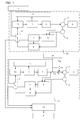
- FIG. 1 is a block diagram showing a servo motor drive system using the collision detector of the present invention.
- the servo motor drive system includes N joints and each joint has a corresponding collision detector.
- the system also includes a fundamental axis control block 20 and a wrist axis control block 21.
- a robot arm for a typical industrial robot uses six-axes control as disclosed in, for example, Japanese Unexamined Patent Application Publication No. 2007-326151 , in which an S-axis, an L-axis, and a U-axis for controlling posture of the robot arm are called fundamental axes, and an R-axis, a B-axis, and a T-axis for controlling posture of an end of the robot arm are called wrist axes.
- a position command generator 1 outputs a position command requested for proper operation of an industrial robot.
- a control section 2 performs proportional control in response to a position command issued from the position command generator 1 and performs proportional-plus-integral control with respect to a speed, thereby issuing a torque command.
- a servo motor 3 runs on a current supplied by the control section 2.
- a robot arm 4 serves as a controlled object driven by the plurality of servo motors 3.
- An encoder 5 detects the position of the servo motor 3.
- a collision detector 6 receives a torque command output from the control section 2 and a rotation signal output from the encoder 5 provided on the servo motor 3, thereby estimating a disturbance to which the robot arm 4 is subjected.
- the collision detector 6 has a disturbance estimation observer that estimates a disturbance acting on the robot arm 4 on the basis of the motor torque and the rotational position of the servo motor 3.
- a collision detection device monitor 7 determines that a collision has occurred when such an estimated disturbance torque exceeds a specified value. If the collision detection device monitor 7 determines that a collision has occurred, a method for stopping the robot is selected by stopping method selection processing 15. Subsequently, in accordance with such a selected method, the robot is stopped by robot stopping processing 9.
- the stopping method selection processing is described below with reference to FIGS. 1 and 2 .
- the collision detector 6 receives a torque command output from the control section 2 and a rotation signal output from the encoder 5 and causes the disturbance estimation observer to estimate a disturbance to which the robot arm 4 is subjected.
- the collision detection device monitor 7 makes a comparison between such an estimated disturbance and the specified value. For all of the N joints, if all estimated disturbances are lower than those of corresponding specified values, the robot operates in accordance with a command issued by the position command generating device 1. If any one of the N joint axes has a disturbance equal to or greater than the specified value, the collision detection device monitor 7 determines that a collision has occurred, and the flow proceeds to step S2.
- step S2 If the collision detection device monitor 7 determines that a collision has occurred, a method for stopping the robot is selected in step S2. If a collision occurred around a fundamental axis, which was detected by the collision detection device monitor 7, the movement around all joints is stopped by a pullback method. If a joint judged by the collision detection device monitor 7 to have sustained a collision is a wrist axis, the flow proceeds to step S3.
- step S3 for an axis for which a collision has been detected, a comparison is made between a motor rotational direction and a direction of a torque generated by the collision, that is, collision torque acting on the servo motor.
- the flow proceeds to step S4 if the motor rotational direction is found to be opposite to the direction of the collision torque.
- the direction of the collision torque is indicated by a sign of the disturbance estimated by the collision detection device 6.
- an axis for which a collision has been detected is a wrist axis and the motor rotational direction is the same as the direction of the collision torque, then the movement around the wrist axis is stopped by flexible stopping processing, while that of the fundamental axis is stopped by immediate stopping processing.
- step S4 a comparison is made between a rotational speed of a servo motor driving the arm around a wrist axis when the collision occurred and a predetermined rotational speed. If the rotational speed of the servo motor for the wrist axis is equal to or greater than the specified value, the robot stops all its movements around all the joint axes including the fundamental axes and the wrist axes by pullback processing.
- an axis for which a collision is detected is a wrist axis and the motor rotational direction is opposite to the direction of the collision torque, and the rotational speed of the servo motor for the wrist axis is not greater than the specified value, then the movement around the wrist axis is stopped by the flexible stopping processing, while that of the fundamental axis is stopped by the immediate stopping processing.
- the robot stopping method can be selected in accordance with an axis for which a collision is detected, a servo motor rotational direction just before a collision, the direction of collision torque, or a servo motor speed.
- the pullback stopping, the flexible stopping, and the immediate stopping processing are described below.
- the pullback processing is described with reference to FIG. 1 .
- the position command generator 1 outputs data on position commands for respective drive axes required for proper operation of the robot arm 4.
- the control section 2 performs proportional control in response to a position command issued from the position command generator 1 and performs proportional-plus-integral control with respect to a speed, thereby issuing a torque command.
- the servo motor 3 runs on a current supplied by the control section 2, causing the robot arm 4 to operate.
- a position memory buffer 8 stores data on a current position of the servo motor 3 read from the encoder 5.
- the collision detector 6 estimates a disturbance that the robot arm 4 is subjected to.
- the collision detection device monitor 7 makes a comparison between such an estimated disturbance and the specified value and determines that a collision has occurred if any one of the joints has a disturbance equal to or greater than the specified value. If a joint judged to have sustained a collision is associated with a fundamental axis, pullback processing is selected by the stopping method selection processing 15, and a switch 12 is closed by the robot stopping processing 9, which initiates the pullback processing, causing all movements around the joints of the robot to be stopped by the pullback processing.
- an axis for which a collision is detected is a wrist axis and the motor rotational direction is opposite to the direction of the collision torque and the rotational speed of the servo motor for the wrist axis is equal to or greater than the specified value
- the pullback processing is selected by the stopping method selection processing 15, and the switch 12 is closed by the robot stopping processing 9, which initiates the pullback processing, causing all movements around the joints including the fundamental axes and the wrist axes to be stopped by the pullback processing.
- Selection of the pullback processing by the stopping method selection processing 15 in FIG. 1 determines a pullback position and a pullback speed on the basis of the positional data stored in the position memory buffer 8.
- the oldest data stored in the memory buffer is set as the pullback position.
- the oldest data shows the most distant position from the collided obstacle.
- Equation 2 gives the pullback velocity, which shows that higher servo motor speeds just before the collision result in higher pullback speeds and longer pullback distances, while lower servo motor speeds result in lower pullback speeds and shorter pullback distances.
- Data of the position ⁇ k2 of the servo motor k3 at the time of detection of a collision and the pullback velocity Vk are output to a position command changing device k9.
- the position command changing device k9 Upon receipt of the data on the position ⁇ k2 of the servo motor k3 at the time of detection of a collision and the pullback velocity Vk from the position memory buffer k8, the position command changing device k9 obtains data of a commanded position ⁇ kr using Equation 3 and outputs it to a position command generator k1.
- Tr is an update period of the position command.
- the position command changing device k9 calculates the commanded position ⁇ kr by increasing I one by one from 1 to T*M/Tr for each update period Tr of the position command and outputs the calculated data to the position command generator k1.
- the commanded position ⁇ kr corresponds to the position ⁇ k1.
- the pullback speed is needed to be increased in proportion to the speed.
- the degree of damage that the robot and the obstacle sustain is proportional to the speed at the time of the collision.
- This embodiment allows the pullback speed to be determined in proportion to the speed of the servo motor following the detection of a collision at that time, thereby minimizing the degree of damage that the robot and the obstacle sustain.
- the distance of pullback increases in proportion to the speed of the servo motor at the time of the collision, ensuring that the robot arm is sufficiently pulled back from the obstacle.
- an axis for which a collision is detected is a fundamental axis
- the robot arm moving around all of the axes are pulled back and stopped, irrespective of the motor rotational direction and the direction of the collision torque. If the motor rotational direction is the same as the direction of the collision torque, an attempt is made to switch the operational mode to the flexible control mode to cause the arm moving around the fundamental axis to move in accordance with a collision in order to reduce the collision torque.
- the arm of the robot moving around the fundamental axis has greater inertia than other parts moving around the wrist axis, if the robot is subjected to flexible stopping processing, the robot moves a large distance after a collision is detected. This poses a concern over recurrence of a collision.
- the all-axis pullback stopping processing is less likely to lead to recurrence of a collision than the flexible processing. Also, the pullback stopping processing pulls back the robot to its trajectory. For this reason, when operated again after the pullback stopping processing, the robot moves along a trajectory instructed at the time of teaching, thereby preventing a collision from recurring.
- an axis for which a collision is detected is a wrist axis and the motor rotational direction of the servo motor driving thereof is opposite to the direction of the collision torque and a rotational speed of the servo motor at the time of the collision is equal to or greater than the specified value
- the rotational speed of the motor is reduced by causing the motor to produce a torque in the opposite direction to the motor rotational direction because the parts moving around the wrist axis has a greater inertia torque.
- collision energy is reduced so that damage to the robot and the obstacle can be minimized.
- the pullback stopping processing pulls back the robot to the desired trajectory. Due to this, when operated again after the pullback stopping processing, the robot moves along a trajectory instructed at the time of teaching, thereby preventing a collision from recurring.
- the flexible stopping processing for the wrist axis and the immediate stopping processing for the fundamental axis are described below. If an axis for which a collision is detected is a wrist axis and the motor rotational direction is the same as the direction of the collision torque, then the movement around the wrist axis is stopped by the flexible stopping processing, while the movement around the fundamental axis is stopped by the immediate stopping processing.
- an axis for which a collision is detected is a wrist axis and the servo motor rotational direction is opposite to the direction of the collision torque and the rotational speed of the servo motor for the wrist axis at the time of the collision is not greater than the specified value, then the movement around the wrist axis is stopped by the flexible stopping processing, while the movement around the fundamental axis is stopped by the immediate stopping processing.
- the control system for the wrist axis in the case where the flexible stopping processing is selected is described below with reference to FIG. 1 .
- the collision detector 6 estimates a disturbance that the robot arm 4 sustains.
- the collision detection device monitor 7 makes a comparison between such an estimated disturbance and the specified value. If any one joint has a disturbance equal to or greater than the specified value, the collision detection device monitor 7 determines that a collision has occurred. If a flexible stopping processing is selected by the stopping method selection processing 15, a switch 13 is opened after a collision is detected, causing a torque command value obtained from the control section 2 to be forcibly set to 0.
- a switch 14 is closed to prevent the arm from falling due to the gravitational force, and a gravity compensation value is added to a torque command value to the servo motor 3.
- Such a gravity compensation value is obtained in advance by calculation based on the posture of the robot arm 4 and weight parameters or by measurement. This allows the robot arm moving around the wrist axis to move in accordance with a collision. Also, the switch 13 is opened and the switch 14 is closed when a collision is detected, and at the same time a position command output from the position command generator 1 at the moment of detection of a collision is output to a return position storage device 11.
- the control system for the fundamental axis in the case where the immediate stopping processing is selected is described below using FIG. 1 .
- a switch 12 is closed by the robot stopping processing 9, which enables the immediate stopping processing.
- the position memory buffer 8 stores a current position of the servo motor 3 read from the encoder 5.
- the collision detector 6 estimates a disturbance that the robot arm 4 sustains.
- the collision detection device monitor 7 makes a comparison between such an estimated disturbance and the specified value and determines that a collision has occurred if any one of the joint axes has a disturbance equal to or greater than the specified value.
- a stopping position is determined on the basis of the positional data stored in the position memory buffer.
- the latest positional data of all the data recorded in the position memory buffer 8 at the moment of detection of a collision is treated as a stopping position. Since the memory buffer 8 contains M pieces of predetermined positional data, the latest data represents a position at which a collision is detected.
- the latest positional data of all the data recorded in the position memory buffer 8 is output to the position command changing device 9.
- the servo motor 3 produces a torque in the opposite direction from that just before the collision, which moves the robot arm 4 to a position at which the collision is detected.
- a position command output from the position command generator 1 at the moment of detection of the collision is output to a return position storage device 11.
- the wrist axis flexible stopping processing and the fundamental axis immediate stopping processing are selected by the stopping method selection processing 15 in the following case; an axis for which a collision is detected is a wrist axis and the motor rotational direction is the same as the direction of the collision torque; and an axis for which a collision is detected is a wrist axis and the motor rotational direction is opposite to the direction of the collision torque and the rotational speed of the servo motor for the wrist axis at the time of a collision is not greater than the specified value. If an axis for which a collision is detected is a wrist axis and the motor rotational direction is the same as the direction of the collision torque, the arm moving around the wrist axis is subjected to the flexible stopping processing.
- the robot moving around the wrist axis goes out of control and deviates from the commanded trajectory.
- the robot arm moves through a trajectory different from that commanded at the time of teaching and is likely to collide with an obstacle. For this reason, if a requirement for an operation of the robot is made again, in order to avoid another collision, before the operation, all parts of the robot arm around respective axes are returned at a low speed to positions for which data are stored in a return position data storage device 11. Since all position data stored in the return position data storage device 11 correspond to those of the commanded trajectory, it is less likely that another collision with an obstacle will be caused. Also, even if the robot arm sustains another collision on the way back to the commanded trajectory, mechanical damages to the robot arm and the obstacle can be minimized since the robot arm is returned at a low speed to the commanded trajectory.
- an axis for which a collision is detected is a wrist axis and the motor rotational direction is opposite to the direction of the collision torque and the rotational speed of the servo motor at the time of the collision for moving the robot around the wrist axis is not greater than the specified value, then the movement around the wrist axis is flexibly stopped, while the movement around the fundamental axis is immediately stopped. If an axis for which a collision is detected is a wrist axis and the rotational speed of the servo motor at the time of the collision for moving the robot around the wrist axis is not greater than the specified value, then mechanical damages to the robot and the obstacle are minimized due to low inertia of the wrist axis.
- the movement around the wrist axis is subjected to flexible stopping instead of a pullback operation.
- This allows the movement around the wrist axis to move in accordance with an external force, expeditiously eliminating distortion that reduction gears suffer from at the time of a collision.
- all parts of the robot arm around respective axes are returned at a low speed to positions for which data are stored in the return position storage device 11. Since all position data stored in the return position data storage device 11 correspond to those of the commanded trajectory, it is less likely that another collision with an obstacle will be caused. Also, even if the robot arm sustains another collision on the way back to the commanded trajectory, mechanical damages to the robot arm and the obstacle can be minimized since the robot arm is returned at a low speed to the commanded trajectory.
Landscapes
- Engineering & Computer Science (AREA)
- Robotics (AREA)
- Mechanical Engineering (AREA)
- Manipulator (AREA)
Abstract
Description
- The present application is related to Japanese Patent application no.
2008-314492 - The present invention relates to a method of controlling a servo motor and a method of controlling a robot system when an abnormal load due to a collision with an object is detected.
- When an arm constituting an industrial robot or an end effector gripped by such an arm collides with an obstacle, a servo motor that continuously drives each arm, during abnormal load detection in response to a given movement command, causes the servo motor to be locked and to produce a large torque. If this situation lasts for an extended period of time, damage to a mechanical arm section including the servo motor and a reduction gear may result. Also, mechanical damage to the obstacle may result.
- There have been proposed, for example, five methods described in the following documents for detecting the occurrence of a collision and immediately suspending a movement command issued to the servo motor; Japanese Unexamined Patent Application Publication No.
6-131050 3-196313 6-245561 6-278081 WO 2005/009692 . - When encountering a collision with an obstacle, the robot system proposed in the above documents can reduce a collision torque by switching its operation mode to a flexible control mode so as to behave in accordance with the strength of a collision force if the rotational direction of a motor is the same as the direction of the collision torque. However, such a switch to the flexible control mode may cause the robot to go out of control, and the robot and the obstacle are subjected to a great impact force if the robot has large inertia at the time of the collision. In particular, if the servo motor driving the robot around the fundamental axis is running at a high speed at the time of the collision, the switch to the flexible control mode causes the robot to move a large distance until its inertia becomes zero, which may cause another collision, resulting in significant mechanical damage to the robot and the obstacle. Also, if all of the joints used in the robot are subjected to the flexible control, the robot largely deviates from a commanded trajectory. For this reason, when operated again after the detection of the collision, the robot moves through a trajectory other than that commanded at the time of teaching, which may cause a collision with an obstacle.
- Accordingly, it is an object of the present invention to provide a method of stopping a robot that minimizes mechanical damage to the robot and an obstacle by selecting a method for stopping movement around a wrist axis and fundamental axis. The selection depends on the axis a collision is detected for, the rotational direction of a motor and the direction of a collision torque, and a motor speed when a servo motor or a multi-jointed robot having such a servo motor collides with an obstacle. It is another object of the present invention to provide a return method for avoiding another collision when the robot is operated again following the detection of the collision.
- According to one aspect of the present invention, a robot system includes a robot arm driven by a motor, a collision detector for detecting collision of the robot arm with an obstacle, and a stopping method selector for selecting a stopping method from among a plurality of stopping methods on the basis of the information obtained by the collision detector, thereby selecting a stopping method depending on the status of the collision.
- According to another aspect of the present invention, a robot system control method includes the steps of controlling the robot arm by controlling the motor when a collision is detected during an operation of the robot arm and causing the stopping method selector to stop the robot arm by any one of all stopping methods.
- According to a further aspect of the present invention, the robot system control method includes the steps of controlling a robot arm by controlling a servo motor when a collision is detected during an operation of the robot arm and storing the positional data given at the moment of the detection of the collision. The robot system control method further includes the steps of moving all parts of the robot arm around respective axes at a low speed to the positions the parts were at when the collision occurred and operating the robot system again if required.
- A more complete appreciation of the invention and many of the attendant advantages thereof will be readily obtained as the same becomes better understood by reference to the following detailed description when considered in connection with the accompanying drawings, wherein:
-
FIG. 1 is a block diagram according to an embodiment of the present invention; and -
FIG. 2 is a flowchart according to an embodiment of the present invention. - Embodiments will now be described with reference to the accompanying drawings, wherein like reference numerals designate corresponding or identical elements throughout the various drawings.
-
FIG. 1 is a block diagram showing a servo motor drive system using the collision detector of the present invention. The servo motor drive system includes N joints and each joint has a corresponding collision detector. The system also includes a fundamentalaxis control block 20 and a wristaxis control block 21. - A robot arm for a typical industrial robot uses six-axes control as disclosed in, for example, Japanese Unexamined Patent Application Publication No.
2007-326151 - In the block diagram, a
position command generator 1 outputs a position command requested for proper operation of an industrial robot. Acontrol section 2 performs proportional control in response to a position command issued from theposition command generator 1 and performs proportional-plus-integral control with respect to a speed, thereby issuing a torque command. Aservo motor 3 runs on a current supplied by thecontrol section 2. Arobot arm 4 serves as a controlled object driven by the plurality ofservo motors 3. Anencoder 5 detects the position of theservo motor 3. Acollision detector 6 receives a torque command output from thecontrol section 2 and a rotation signal output from theencoder 5 provided on theservo motor 3, thereby estimating a disturbance to which therobot arm 4 is subjected. Thecollision detector 6 has a disturbance estimation observer that estimates a disturbance acting on therobot arm 4 on the basis of the motor torque and the rotational position of theservo motor 3. A collisiondetection device monitor 7 determines that a collision has occurred when such an estimated disturbance torque exceeds a specified value. If the collisiondetection device monitor 7 determines that a collision has occurred, a method for stopping the robot is selected by stoppingmethod selection processing 15. Subsequently, in accordance with such a selected method, the robot is stopped byrobot stopping processing 9. - The stopping method selection processing is described below with reference to
FIGS. 1 and2 . Thecollision detector 6 receives a torque command output from thecontrol section 2 and a rotation signal output from theencoder 5 and causes the disturbance estimation observer to estimate a disturbance to which therobot arm 4 is subjected. The collisiondetection device monitor 7 makes a comparison between such an estimated disturbance and the specified value. For all of the N joints, if all estimated disturbances are lower than those of corresponding specified values, the robot operates in accordance with a command issued by the positioncommand generating device 1. If any one of the N joint axes has a disturbance equal to or greater than the specified value, the collisiondetection device monitor 7 determines that a collision has occurred, and the flow proceeds to step S2. - If the collision
detection device monitor 7 determines that a collision has occurred, a method for stopping the robot is selected in step S2. If a collision occurred around a fundamental axis, which was detected by the collisiondetection device monitor 7, the movement around all joints is stopped by a pullback method. If a joint judged by the collisiondetection device monitor 7 to have sustained a collision is a wrist axis, the flow proceeds to step S3. - In step S3, for an axis for which a collision has been detected, a comparison is made between a motor rotational direction and a direction of a torque generated by the collision, that is, collision torque acting on the servo motor. The flow proceeds to step S4 if the motor rotational direction is found to be opposite to the direction of the collision torque. The direction of the collision torque is indicated by a sign of the disturbance estimated by the
collision detection device 6. - If an axis for which a collision has been detected is a wrist axis and the motor rotational direction is the same as the direction of the collision torque, then the movement around the wrist axis is stopped by flexible stopping processing, while that of the fundamental axis is stopped by immediate stopping processing.
- In step S4, a comparison is made between a rotational speed of a servo motor driving the arm around a wrist axis when the collision occurred and a predetermined rotational speed. If the rotational speed of the servo motor for the wrist axis is equal to or greater than the specified value, the robot stops all its movements around all the joint axes including the fundamental axes and the wrist axes by pullback processing.
- If an axis for which a collision is detected is a wrist axis and the motor rotational direction is opposite to the direction of the collision torque, and the rotational speed of the servo motor for the wrist axis is not greater than the specified value, then the movement around the wrist axis is stopped by the flexible stopping processing, while that of the fundamental axis is stopped by the immediate stopping processing.
- The robot stopping method can be selected in accordance with an axis for which a collision is detected, a servo motor rotational direction just before a collision, the direction of collision torque, or a servo motor speed. The pullback stopping, the flexible stopping, and the immediate stopping processing are described below.
- The pullback processing is described with reference to
FIG. 1 . Theposition command generator 1 outputs data on position commands for respective drive axes required for proper operation of therobot arm 4. Thecontrol section 2 performs proportional control in response to a position command issued from theposition command generator 1 and performs proportional-plus-integral control with respect to a speed, thereby issuing a torque command. Theservo motor 3 runs on a current supplied by thecontrol section 2, causing therobot arm 4 to operate. Aposition memory buffer 8 stores data on a current position of theservo motor 3 read from theencoder 5. Thecollision detector 6 estimates a disturbance that therobot arm 4 is subjected to. The collision detection device monitor 7 makes a comparison between such an estimated disturbance and the specified value and determines that a collision has occurred if any one of the joints has a disturbance equal to or greater than the specified value. If a joint judged to have sustained a collision is associated with a fundamental axis, pullback processing is selected by the stoppingmethod selection processing 15, and aswitch 12 is closed by therobot stopping processing 9, which initiates the pullback processing, causing all movements around the joints of the robot to be stopped by the pullback processing. Alternatively, if an axis for which a collision is detected is a wrist axis and the motor rotational direction is opposite to the direction of the collision torque and the rotational speed of the servo motor for the wrist axis is equal to or greater than the specified value, then the pullback processing is selected by the stoppingmethod selection processing 15, and theswitch 12 is closed by therobot stopping processing 9, which initiates the pullback processing, causing all movements around the joints including the fundamental axes and the wrist axes to be stopped by the pullback processing. - Selection of the pullback processing by the stopping
method selection processing 15 inFIG. 1 determines a pullback position and a pullback speed on the basis of the positional data stored in theposition memory buffer 8. The oldest data stored in the memory buffer is set as the pullback position. Of the M pieces of the positional data stored in the memory buffer in advance, the oldest data shows the most distant position from the collided obstacle. The pullback distance θk is calculated from the data on pullback position θk1 and the position θk2 of the servo motor k3 at the time of detection of a collision using Equation 1:
- The memory buffer has data recorded at constant intervals of time. Assuming the length of the interval is T, the pullback velocity Vk is calculated from the pullback distance θk, the interval T at which data is stored in the position memory buffer, and the number of pieces of data M to be stored in the position memory buffer using Equation 2:

-
Equation 2 gives the pullback velocity, which shows that higher servo motor speeds just before the collision result in higher pullback speeds and longer pullback distances, while lower servo motor speeds result in lower pullback speeds and shorter pullback distances. - Data of the position θk2 of the servo motor k3 at the time of detection of a collision and the pullback velocity Vk are output to a position command changing device k9. Upon receipt of the data on the position θk2 of the servo motor k3 at the time of detection of a collision and the pullback velocity Vk from the position memory buffer k8, the position command changing device k9 obtains data of a commanded position
θkr using Equation 3 and outputs it to a position command generator k1.
- Here, Tr is an update period of the position command. Using
Equation 3, the position command changing device k9 calculates the commanded position θkr by increasing I one by one from 1 to T*M/Tr for each update period Tr of the position command and outputs the calculated data to the position command generator k1. When the number of update events for the position command is T*M/Tr, the commanded position θkr corresponds to the position θk1. By updating the position command toward θk1 from θk2, a torque in the opposite direction from that just before the collision is produced in the servo motor, which moves the robot away from the obstacle. Higher servo motor speeds just before the collision result in higher pullback speeds and longer pullback distances, while lower servo motor speeds result in lower pullback speeds and shorter pullback distances. - If the rotational speed of a servo motor at the time of a collision is high, the distance by which the robot overruns becomes long. In order to sufficiently pull back the robot from the obstacle, the distance of pullback is needed to be increased. Also, since the degree of damage that the robot and the obstacle sustain is proportional to the speed at the time of the collision, the pullback speed is needed to be increased in proportion to the speed.
- The degree of damage that the robot and the obstacle sustain is proportional to the speed at the time of the collision. This embodiment allows the pullback speed to be determined in proportion to the speed of the servo motor following the detection of a collision at that time, thereby minimizing the degree of damage that the robot and the obstacle sustain. The distance of pullback increases in proportion to the speed of the servo motor at the time of the collision, ensuring that the robot arm is sufficiently pulled back from the obstacle.
- If an axis for which a collision is detected is a fundamental axis, the robot arm moving around all of the axes are pulled back and stopped, irrespective of the motor rotational direction and the direction of the collision torque. If the motor rotational direction is the same as the direction of the collision torque, an attempt is made to switch the operational mode to the flexible control mode to cause the arm moving around the fundamental axis to move in accordance with a collision in order to reduce the collision torque. However, since the arm of the robot moving around the fundamental axis has greater inertia than other parts moving around the wrist axis, if the robot is subjected to flexible stopping processing, the robot moves a large distance after a collision is detected. This poses a concern over recurrence of a collision. Accordingly, if a collision is detected for a fundamental axis, regardless of the motor rotational direction and the direction of the collision torque, the all-axis pullback stopping processing is less likely to lead to recurrence of a collision than the flexible processing. Also, the pullback stopping processing pulls back the robot to its trajectory. For this reason, when operated again after the pullback stopping processing, the robot moves along a trajectory instructed at the time of teaching, thereby preventing a collision from recurring.
- If an axis for which a collision is detected is a wrist axis and the motor rotational direction of the servo motor driving thereof is opposite to the direction of the collision torque and a rotational speed of the servo motor at the time of the collision is equal to or greater than the specified value, then the rotational speed of the motor is reduced by causing the motor to produce a torque in the opposite direction to the motor rotational direction because the parts moving around the wrist axis has a greater inertia torque. Thereby collision energy is reduced so that damage to the robot and the obstacle can be minimized. Also, the pullback stopping processing pulls back the robot to the desired trajectory. Due to this, when operated again after the pullback stopping processing, the robot moves along a trajectory instructed at the time of teaching, thereby preventing a collision from recurring.
- Then, the flexible stopping processing for the wrist axis and the immediate stopping processing for the fundamental axis are described below. If an axis for which a collision is detected is a wrist axis and the motor rotational direction is the same as the direction of the collision torque, then the movement around the wrist axis is stopped by the flexible stopping processing, while the movement around the fundamental axis is stopped by the immediate stopping processing. Alternatively, if an axis for which a collision is detected is a wrist axis and the servo motor rotational direction is opposite to the direction of the collision torque and the rotational speed of the servo motor for the wrist axis at the time of the collision is not greater than the specified value, then the movement around the wrist axis is stopped by the flexible stopping processing, while the movement around the fundamental axis is stopped by the immediate stopping processing.
- The control system for the wrist axis in the case where the flexible stopping processing is selected is described below with reference to
FIG. 1 . Thecollision detector 6 estimates a disturbance that therobot arm 4 sustains. The collision detection device monitor 7 makes a comparison between such an estimated disturbance and the specified value. If any one joint has a disturbance equal to or greater than the specified value, the collision detection device monitor 7 determines that a collision has occurred. If a flexible stopping processing is selected by the stoppingmethod selection processing 15, aswitch 13 is opened after a collision is detected, causing a torque command value obtained from thecontrol section 2 to be forcibly set to 0. Aswitch 14 is closed to prevent the arm from falling due to the gravitational force, and a gravity compensation value is added to a torque command value to theservo motor 3. Such a gravity compensation value is obtained in advance by calculation based on the posture of therobot arm 4 and weight parameters or by measurement. This allows the robot arm moving around the wrist axis to move in accordance with a collision. Also, theswitch 13 is opened and theswitch 14 is closed when a collision is detected, and at the same time a position command output from theposition command generator 1 at the moment of detection of a collision is output to a returnposition storage device 11. - The control system for the fundamental axis in the case where the immediate stopping processing is selected is described below using
FIG. 1 . When the immediate stopping processing is selected by the stoppingmethod selection processing 15, aswitch 12 is closed by therobot stopping processing 9, which enables the immediate stopping processing. Theposition memory buffer 8 stores a current position of theservo motor 3 read from theencoder 5. Thecollision detector 6 estimates a disturbance that therobot arm 4 sustains. The collision detection device monitor 7 makes a comparison between such an estimated disturbance and the specified value and determines that a collision has occurred if any one of the joint axes has a disturbance equal to or greater than the specified value. When the immediate stopping processing is selected by the stopping method selection processing, a stopping position is determined on the basis of the positional data stored in the position memory buffer. The latest positional data of all the data recorded in theposition memory buffer 8 at the moment of detection of a collision is treated as a stopping position. Since thememory buffer 8 contains M pieces of predetermined positional data, the latest data represents a position at which a collision is detected. The latest positional data of all the data recorded in theposition memory buffer 8 is output to the positioncommand changing device 9. Theservo motor 3 produces a torque in the opposite direction from that just before the collision, which moves therobot arm 4 to a position at which the collision is detected. A position command output from theposition command generator 1 at the moment of detection of the collision is output to a returnposition storage device 11. - The wrist axis flexible stopping processing and the fundamental axis immediate stopping processing are selected by the stopping
method selection processing 15 in the following case; an axis for which a collision is detected is a wrist axis and the motor rotational direction is the same as the direction of the collision torque; and an axis for which a collision is detected is a wrist axis and the motor rotational direction is opposite to the direction of the collision torque and the rotational speed of the servo motor for the wrist axis at the time of a collision is not greater than the specified value. If an axis for which a collision is detected is a wrist axis and the motor rotational direction is the same as the direction of the collision torque, the arm moving around the wrist axis is subjected to the flexible stopping processing. This causes the arm moving around the wrist axis to move in accordance with a collision, reducing a collision torque. At this time, it is conceivable that an arm moving around the fundamental axis is also subjected to the flexible stopping processing. However, if the arm moving around the fundamental axis having greater inertia than that moving around the wrist axis is subjected to the flexible stopping processing, the robot moves a large distance after a collision is detected. That poses a concern over recurrence of a collision. A robot moving around the fundamental axis is subjected to the immediate stopping processing, instead of the flexible stopping processing, which causes the robot to move to a position at which a collision is detected. - After subjected to the wrist axis flexible stopping processing or the fundamental axis immediate stopping processing, the robot moving around the wrist axis goes out of control and deviates from the commanded trajectory. When operated again after stopped, the robot arm moves through a trajectory different from that commanded at the time of teaching and is likely to collide with an obstacle. For this reason, if a requirement for an operation of the robot is made again, in order to avoid another collision, before the operation, all parts of the robot arm around respective axes are returned at a low speed to positions for which data are stored in a return position
data storage device 11. Since all position data stored in the return positiondata storage device 11 correspond to those of the commanded trajectory, it is less likely that another collision with an obstacle will be caused. Also, even if the robot arm sustains another collision on the way back to the commanded trajectory, mechanical damages to the robot arm and the obstacle can be minimized since the robot arm is returned at a low speed to the commanded trajectory. - If an axis for which a collision is detected is a wrist axis and the motor rotational direction is opposite to the direction of the collision torque and the rotational speed of the servo motor at the time of the collision for moving the robot around the wrist axis is not greater than the specified value, then the movement around the wrist axis is flexibly stopped, while the movement around the fundamental axis is immediately stopped. If an axis for which a collision is detected is a wrist axis and the rotational speed of the servo motor at the time of the collision for moving the robot around the wrist axis is not greater than the specified value, then mechanical damages to the robot and the obstacle are minimized due to low inertia of the wrist axis. Accordingly, the movement around the wrist axis is subjected to flexible stopping instead of a pullback operation. This allows the movement around the wrist axis to move in accordance with an external force, expeditiously eliminating distortion that reduction gears suffer from at the time of a collision. If a requirement for an operation of the robot is made again, in order to avoid another collision, before the operation, all parts of the robot arm around respective axes are returned at a low speed to positions for which data are stored in the return
position storage device 11. Since all position data stored in the return positiondata storage device 11 correspond to those of the commanded trajectory, it is less likely that another collision with an obstacle will be caused. Also, even if the robot arm sustains another collision on the way back to the commanded trajectory, mechanical damages to the robot arm and the obstacle can be minimized since the robot arm is returned at a low speed to the commanded trajectory.
Claims (12)
- A robot system comprising:a robot arm driven by a motor;a collision detector that detects a collision between the robot arm and an obstacle; anda stopping method selector that controls the robot arm by selecting a stopping method from among a plurality of stopping methods on the basis of the information obtained by the collision detector.
- The robot system according to Claim 1, wherein the stopping method selector selects a stopping method on the basis of the information obtained by the collision detector and information on a position of the robot arm at the time of a collision.
- The robot system according to Claim 1 or 2, further comprising a return position storing device that allows the robot arm to move to a predetermined position after the robot arm is stopped by any one of the plurality of stopping methods on the basis of the information obtained by the collision detector.
- The robot system according to Claim 3, wherein the return position storing device stores data on a rotational position of the plurality of motors at constant intervals of time.
- The robot system according to any one of Claims 1 to 4, wherein the collision detector is provided at each of fundamental and wrist axes of the robot arm.
- The robot system according to Claim 5, wherein the wrist axis of the robot arm is provided with a switching device that compensates for gravity and operates in accordance with a stopping method selected by the stopping method selector.
- A method of controlling a robot system, comprising the steps of:controlling a part of a robot arm by controlling a motor when a collision is detected in the robot arm; andcausing a stopping method selector to stop the robot arm by using any one of a plurality of stopping methods.
- The method of controlling the robot system according to claim 7, whereby the stopping method selector causes a part of robot arm moving around a wrist axis to be stopped by flexible stopping processing and causes another part of the robot arm moving around a fundamental axis to be stopped by immediate stopping processing if an axis for which a collision is detected is a wrist axis and a rotational direction of the motor is the same as a direction a collision torque.
- The method of controlling the robot system according to claim 7, whereby the stopping method selector causes a part of the robot arm moving around the wrist axis to be stopped by the flexible stopping processing and causes another part of the robot arm moving around the fundamental axis to be stopped by the immediate stopping processing if an axis for which a collision is detected is a wrist axis and a rotational direction of the motor is opposite to a direction of a collision torque and a servo motor speed for the wrist axis at the time of a collision is not greater than a specified value.
- The method of controlling the robot system according to claim 7, whereby the stopping method selector causes all parts of the robot arm moving around respective axes to be pulled back if an axis for which a collision is detected is a wrist axis and a rotational direction of the motor is opposite to a direction of a collision torque and a servo motor speed for the wrist axis at the time of a collision is equal to or greater than the specified value.
- The method of controlling the robot system according to claim 7, whereby the stopping method selector causes all parts of the robot arm moving around respective axes to be pulled back if an axis for which a collision is detected is a fundamental axis.
- A method of controlling a robot system, comprising the steps of:controlling a part of a robot arm by controlling a motor when a collision is detected;storing a position command data at the moment of the detection of the collision; andreturning all parts of the robot arm moving around respective axes at a low speed to the position for which the position command data are stored before causing the robot arm to be operated again when a requirement for an operation of the robot arm is made.
Applications Claiming Priority (1)
| Application Number | Priority Date | Filing Date | Title |
|---|---|---|---|
| JP2008314492A JP5375062B2 (en) | 2008-12-10 | 2008-12-10 | Robot system and control method |
Publications (3)
| Publication Number | Publication Date |
|---|---|
| EP2199037A2 true EP2199037A2 (en) | 2010-06-23 |
| EP2199037A3 EP2199037A3 (en) | 2011-10-26 |
| EP2199037B1 EP2199037B1 (en) | 2013-01-23 |
Family
ID=42078820
Family Applications (1)
| Application Number | Title | Priority Date | Filing Date |
|---|---|---|---|
| EP09168310A Active EP2199037B1 (en) | 2008-12-10 | 2009-08-20 | Robot system and control method |
Country Status (3)
| Country | Link |
|---|---|
| US (1) | US8423189B2 (en) |
| EP (1) | EP2199037B1 (en) |
| JP (1) | JP5375062B2 (en) |
Cited By (2)
| Publication number | Priority date | Publication date | Assignee | Title |
|---|---|---|---|---|
| WO2012019733A1 (en) * | 2010-08-09 | 2012-02-16 | Dürr Systems GmbH | Control system and control method for a robot |
| US9409295B2 (en) | 2013-08-20 | 2016-08-09 | Kuka Roboter Gmbh | Method for controlling a robot |
Families Citing this family (30)
| Publication number | Priority date | Publication date | Assignee | Title |
|---|---|---|---|---|
| JP5365595B2 (en) * | 2010-09-15 | 2013-12-11 | 株式会社安川電機 | Speed reducer abnormality determination method, abnormality determination apparatus, robot, and robot system |
| DE102013000250A1 (en) | 2013-01-09 | 2014-07-10 | Kuka Laboratories Gmbh | Configurable security monitoring for a robot arrangement |
| DE102013016019B3 (en) * | 2013-09-25 | 2015-03-19 | Festo Ag & Co. Kg | Method for operating a multi-unit manipulator |
| DE202013105036U1 (en) * | 2013-11-08 | 2015-02-10 | Daimler Ag | detector |
| US9452532B2 (en) * | 2014-01-27 | 2016-09-27 | Panasonic Intellectual Property Management Co., Ltd. | Robot, device and method for controlling robot, and computer-readable non-transitory recording medium |
| JP5926346B2 (en) | 2014-09-25 | 2016-05-25 | ファナック株式会社 | Human cooperation robot system |
| US9676097B1 (en) * | 2014-11-11 | 2017-06-13 | X Development Llc | Systems and methods for robotic device authentication |
| DE102015200355B3 (en) * | 2015-01-02 | 2016-01-28 | Siemens Aktiengesellschaft | A medical robotic device with collision detection and method for collision detection of a medical robotic device |
| JP5937706B1 (en) * | 2015-01-21 | 2016-06-22 | ファナック株式会社 | Robot control apparatus and robot system for controlling robot based on external force applied to robot |
| DE102015017296B3 (en) | 2015-08-14 | 2021-10-07 | Franka Emika Gmbh | Robotic system |
| JP6794194B2 (en) * | 2015-09-17 | 2020-12-02 | キヤノン株式会社 | Manufacturing methods for robotic devices, control methods, programs, recording media and articles |
| DE102015012961B4 (en) | 2015-10-08 | 2022-05-05 | Kastanienbaum GmbH | robotic system |
| DE102015012962B4 (en) | 2015-10-08 | 2024-08-22 | Franka Emika Gmbh | Robot system |
| DE102015012959B4 (en) | 2015-10-08 | 2019-01-17 | Franka Emika Gmbh | Robot system and method for controlling a robot system |
| KR101734241B1 (en) * | 2015-12-10 | 2017-05-11 | 현대자동차 주식회사 | Trunk lid hinge intellectual loader unit |
| US10082783B2 (en) * | 2015-12-17 | 2018-09-25 | Feng-Tien Chen | Computer numerical control servo drive system |
| JP6733239B2 (en) * | 2016-03-18 | 2020-07-29 | セイコーエプソン株式会社 | Controller and robot system |
| CN107294428A (en) * | 2016-04-08 | 2017-10-24 | 陈丰田 | CNC SERVO CONTROL drive systems |
| DE102016004787B4 (en) | 2016-04-20 | 2023-02-02 | Franka Emika Gmbh | Driving device for a robot and method for its manufacture |
| DE102016004788A1 (en) | 2016-04-20 | 2017-10-26 | Kastanienbaum GmbH | Method for producing a robot and device for carrying out this method |
| DE102016210060A1 (en) * | 2016-06-08 | 2017-12-14 | Kuka Roboter Gmbh | Method for safely stopping a manipulator |
| US9981383B1 (en) * | 2016-08-02 | 2018-05-29 | X Development Llc | Real-time trajectory generation for actuators of a robot to reduce chance of collision with obstacle(s) |
| JP6939104B2 (en) * | 2017-06-09 | 2021-09-22 | セイコーエプソン株式会社 | Control devices, robot systems and robot control methods |
| JP6948164B2 (en) * | 2017-06-12 | 2021-10-13 | 日立Geニュークリア・エナジー株式会社 | Work robot arm attitude control system and method |
| CN107466263A (en) * | 2017-07-10 | 2017-12-12 | 深圳市艾唯尔科技有限公司 | A kind of joint of robot anticollision protection system and its method for sensing integration technology |
| KR102418451B1 (en) | 2017-12-27 | 2022-07-07 | 주식회사 한화 | Robot control system |
| CN112060072B (en) * | 2019-06-11 | 2023-06-20 | 华邦电子股份有限公司 | Collaborative robot control system and method |
| US11628568B2 (en) | 2020-12-28 | 2023-04-18 | Industrial Technology Research Institute | Cooperative robotic arm system and homing method thereof |
| CN114872034A (en) * | 2022-06-16 | 2022-08-09 | 北京市商汤科技开发有限公司 | A mechanical arm driving structure, arm-type robot and driving method |
| JP7398024B1 (en) * | 2023-07-04 | 2023-12-13 | 株式会社ユーシン精機 | Collision detection method and collision detection system |
Citations (6)
| Publication number | Priority date | Publication date | Assignee | Title |
|---|---|---|---|---|
| JPH03196313A (en) | 1989-12-26 | 1991-08-27 | Fanuc Ltd | Collision detection method by disturbance estimating observer |
| JPH06131050A (en) | 1992-10-20 | 1994-05-13 | Fanuc Ltd | Method for detecting collision of movable part driven by servo motor |
| JPH06245561A (en) | 1993-02-10 | 1994-09-02 | Fanuc Ltd | Abnormal load detection control method for servo motor |
| JPH06278081A (en) | 1993-03-26 | 1994-10-04 | Nec Corp | Robot arm provided with collision prevention function |
| WO2005009692A1 (en) | 2003-07-29 | 2005-02-03 | Matsushita Electric Industrial Co., Ltd. | Robot arm control method and control device |
| JP2007326151A (en) | 2001-10-22 | 2007-12-20 | Yaskawa Electric Corp | Industrial robot |
Family Cites Families (19)
| Publication number | Priority date | Publication date | Assignee | Title |
|---|---|---|---|---|
| JPS57168306A (en) * | 1981-04-08 | 1982-10-16 | Daihen Corp | Controlling method of industrial robot |
| JPH0619657B2 (en) * | 1983-12-09 | 1994-03-16 | 株式会社日立製作所 | Robot control method and apparatus |
| JPS6158002A (en) * | 1984-08-28 | 1986-03-25 | Toyota Motor Corp | Controller of robot |
| JPH06102315B2 (en) * | 1985-12-16 | 1994-12-14 | 株式会社安川電機 | Shock absorption method |
| JPH033687A (en) * | 1989-05-31 | 1991-01-09 | Fanuc Ltd | Method of preventing collision damage of body driven by servo motor |
| JP2633696B2 (en) * | 1989-09-20 | 1997-07-23 | 本田技研工業株式会社 | Robot control system |
| US5304906A (en) | 1989-12-26 | 1994-04-19 | Fanuc Ltd. | Collision detecting method using an observer |
| JP2871993B2 (en) * | 1993-03-31 | 1999-03-17 | 日本電気株式会社 | Servo motor position control device |
| JP3460761B2 (en) * | 1995-09-11 | 2003-10-27 | 株式会社安川電機 | Robot control device |
| JP3327205B2 (en) * | 1998-03-30 | 2002-09-24 | 松下電器産業株式会社 | Robot control method and device |
| JP2000246684A (en) * | 1999-02-26 | 2000-09-12 | Sharp Corp | Arm type robot |
| JP2000277039A (en) * | 1999-03-26 | 2000-10-06 | Toshiba Corp | Image display device and method of manufacturing the same |
| JP3212571B2 (en) * | 1999-03-26 | 2001-09-25 | ファナック株式会社 | Industrial robot |
| JP3459973B2 (en) * | 1999-10-22 | 2003-10-27 | 川崎重工業株式会社 | Drive control method and drive control device |
| JP2001260061A (en) * | 2000-03-15 | 2001-09-25 | Kawasaki Heavy Ind Ltd | How to restart the robot |
| JP2003236787A (en) * | 2002-02-18 | 2003-08-26 | Kawasaki Heavy Ind Ltd | Drive control method and drive control device |
| US6892512B2 (en) * | 2002-08-07 | 2005-05-17 | Medco Health Solutions, Inc. | Automated prescription filling system/method with automated labeling and packaging system/method automated order consolidation system/method |
| JP2005100143A (en) * | 2003-09-25 | 2005-04-14 | Kobe Steel Ltd | Control method and control device for motor-driven device |
| US20060178775A1 (en) * | 2005-02-04 | 2006-08-10 | George Zhang | Accelerometer to monitor movement of a tool assembly attached to a robot end effector |
-
2008
- 2008-12-10 JP JP2008314492A patent/JP5375062B2/en active Active
-
2009
- 2009-08-10 US US12/538,167 patent/US8423189B2/en active Active
- 2009-08-20 EP EP09168310A patent/EP2199037B1/en active Active
Patent Citations (6)
| Publication number | Priority date | Publication date | Assignee | Title |
|---|---|---|---|---|
| JPH03196313A (en) | 1989-12-26 | 1991-08-27 | Fanuc Ltd | Collision detection method by disturbance estimating observer |
| JPH06131050A (en) | 1992-10-20 | 1994-05-13 | Fanuc Ltd | Method for detecting collision of movable part driven by servo motor |
| JPH06245561A (en) | 1993-02-10 | 1994-09-02 | Fanuc Ltd | Abnormal load detection control method for servo motor |
| JPH06278081A (en) | 1993-03-26 | 1994-10-04 | Nec Corp | Robot arm provided with collision prevention function |
| JP2007326151A (en) | 2001-10-22 | 2007-12-20 | Yaskawa Electric Corp | Industrial robot |
| WO2005009692A1 (en) | 2003-07-29 | 2005-02-03 | Matsushita Electric Industrial Co., Ltd. | Robot arm control method and control device |
Cited By (2)
| Publication number | Priority date | Publication date | Assignee | Title |
|---|---|---|---|---|
| WO2012019733A1 (en) * | 2010-08-09 | 2012-02-16 | Dürr Systems GmbH | Control system and control method for a robot |
| US9409295B2 (en) | 2013-08-20 | 2016-08-09 | Kuka Roboter Gmbh | Method for controlling a robot |
Also Published As
| Publication number | Publication date |
|---|---|
| JP2010137312A (en) | 2010-06-24 |
| EP2199037B1 (en) | 2013-01-23 |
| US8423189B2 (en) | 2013-04-16 |
| EP2199037A3 (en) | 2011-10-26 |
| JP5375062B2 (en) | 2013-12-25 |
| US20100145515A1 (en) | 2010-06-10 |
Similar Documents
| Publication | Publication Date | Title |
|---|---|---|
| EP2199037B1 (en) | Robot system and control method | |
| US9421687B2 (en) | Robot control apparatus and robot control method | |
| US9321177B2 (en) | Reducer abnormality determination method, abnormality determination device, and robot system | |
| EP1477284B1 (en) | Drive control method and drive controller | |
| JP4294646B2 (en) | Robot arm control method and control apparatus | |
| JP3459973B2 (en) | Drive control method and drive control device | |
| JP5383911B2 (en) | Robot controller | |
| KR100439466B1 (en) | Robot controller | |
| US10690558B2 (en) | Robot collision detection method | |
| JP4756618B2 (en) | Collision detection / stop control method for articulated robots | |
| JP4550849B2 (en) | Mobile robot with arm | |
| JP4335286B2 (en) | Robot control apparatus and robot control method having component protection function | |
| US6298283B1 (en) | Industrial robot | |
| DK2492062T3 (en) | industrial Robot | |
| EP3683022A1 (en) | Device and method for controlling cooperative robot | |
| KR910009266B1 (en) | Speed control method and device for industrial robot | |
| US8886360B2 (en) | Motor velocity control apparatus and method | |
| US7328123B2 (en) | System for collision avoidance of rotary atomizer | |
| JP2006116650A (en) | Robot collision detection method | |
| JP2009045678A (en) | Robot work success / failure determination method and robot system | |
| JP7469588B2 (en) | Control device for articulated robot and articulated robot | |
| JPH11245191A (en) | Method and device for controlling driving shaft of industrial robot | |
| Tungpataratanawong et al. | Force sensorless workspace impedance control considering resonant vibration of industrial robot | |
| JP7327991B2 (en) | Control method, control program, recording medium, robot system, article manufacturing method, and input device | |
| JP2020097085A (en) | Robot device inspection method, program, recording medium, robot system, and article manufacturing method |
Legal Events
| Date | Code | Title | Description |
|---|---|---|---|
| PUAI | Public reference made under article 153(3) epc to a published international application that has entered the european phase |
Free format text: ORIGINAL CODE: 0009012 |
|
| AK | Designated contracting states |
Kind code of ref document: A2 Designated state(s): AT BE BG CH CY CZ DE DK EE ES FI FR GB GR HR HU IE IS IT LI LT LU LV MC MK MT NL NO PL PT RO SE SI SK SM TR |
|
| PUAL | Search report despatched |
Free format text: ORIGINAL CODE: 0009013 |
|
| AK | Designated contracting states |
Kind code of ref document: A3 Designated state(s): AT BE BG CH CY CZ DE DK EE ES FI FR GB GR HR HU IE IS IT LI LT LU LV MC MK MT NL NO PL PT RO SE SI SK SM TR |
|
| RIC1 | Information provided on ipc code assigned before grant |
Ipc: B25J 9/16 20060101AFI20110920BHEP |
|
| 17P | Request for examination filed |
Effective date: 20120426 |
|
| GRAP | Despatch of communication of intention to grant a patent |
Free format text: ORIGINAL CODE: EPIDOSNIGR1 |
|
| GRAS | Grant fee paid |
Free format text: ORIGINAL CODE: EPIDOSNIGR3 |
|
| GRAA | (expected) grant |
Free format text: ORIGINAL CODE: 0009210 |
|
| AK | Designated contracting states |
Kind code of ref document: B1 Designated state(s): AT BE BG CH CY CZ DE DK EE ES FI FR GB GR HR HU IE IS IT LI LT LU LV MC MK MT NL NO PL PT RO SE SI SK SM TR |
|
| REG | Reference to a national code |
Ref country code: GB Ref legal event code: FG4D |
|
| REG | Reference to a national code |
Ref country code: CH Ref legal event code: EP |
|
| REG | Reference to a national code |
Ref country code: AT Ref legal event code: REF Ref document number: 594694 Country of ref document: AT Kind code of ref document: T Effective date: 20130215 Ref country code: CH Ref legal event code: EP |
|
| REG | Reference to a national code |
Ref country code: IE Ref legal event code: FG4D |
|
| REG | Reference to a national code |
Ref country code: DE Ref legal event code: R096 Ref document number: 602009012950 Country of ref document: DE Effective date: 20130321 |
|
| REG | Reference to a national code |
Ref country code: SE Ref legal event code: TRGR |
|
| REG | Reference to a national code |
Ref country code: AT Ref legal event code: MK05 Ref document number: 594694 Country of ref document: AT Kind code of ref document: T Effective date: 20130123 |
|
| REG | Reference to a national code |
Ref country code: LT Ref legal event code: MG4D |
|
| REG | Reference to a national code |
Ref country code: NL Ref legal event code: VDEP Effective date: 20130123 |
|
| PG25 | Lapsed in a contracting state [announced via postgrant information from national office to epo] |
Ref country code: BG Free format text: LAPSE BECAUSE OF FAILURE TO SUBMIT A TRANSLATION OF THE DESCRIPTION OR TO PAY THE FEE WITHIN THE PRESCRIBED TIME-LIMIT Effective date: 20130423 Ref country code: IS Free format text: LAPSE BECAUSE OF FAILURE TO SUBMIT A TRANSLATION OF THE DESCRIPTION OR TO PAY THE FEE WITHIN THE PRESCRIBED TIME-LIMIT Effective date: 20130523 Ref country code: LT Free format text: LAPSE BECAUSE OF FAILURE TO SUBMIT A TRANSLATION OF THE DESCRIPTION OR TO PAY THE FEE WITHIN THE PRESCRIBED TIME-LIMIT Effective date: 20130123 Ref country code: NO Free format text: LAPSE BECAUSE OF FAILURE TO SUBMIT A TRANSLATION OF THE DESCRIPTION OR TO PAY THE FEE WITHIN THE PRESCRIBED TIME-LIMIT Effective date: 20130423 Ref country code: BE Free format text: LAPSE BECAUSE OF FAILURE TO SUBMIT A TRANSLATION OF THE DESCRIPTION OR TO PAY THE FEE WITHIN THE PRESCRIBED TIME-LIMIT Effective date: 20130123 Ref country code: ES Free format text: LAPSE BECAUSE OF FAILURE TO SUBMIT A TRANSLATION OF THE DESCRIPTION OR TO PAY THE FEE WITHIN THE PRESCRIBED TIME-LIMIT Effective date: 20130504 Ref country code: AT Free format text: LAPSE BECAUSE OF FAILURE TO SUBMIT A TRANSLATION OF THE DESCRIPTION OR TO PAY THE FEE WITHIN THE PRESCRIBED TIME-LIMIT Effective date: 20130123 |
|
| PG25 | Lapsed in a contracting state [announced via postgrant information from national office to epo] |
Ref country code: NL Free format text: LAPSE BECAUSE OF FAILURE TO SUBMIT A TRANSLATION OF THE DESCRIPTION OR TO PAY THE FEE WITHIN THE PRESCRIBED TIME-LIMIT Effective date: 20130123 Ref country code: PT Free format text: LAPSE BECAUSE OF FAILURE TO SUBMIT A TRANSLATION OF THE DESCRIPTION OR TO PAY THE FEE WITHIN THE PRESCRIBED TIME-LIMIT Effective date: 20130523 Ref country code: GR Free format text: LAPSE BECAUSE OF FAILURE TO SUBMIT A TRANSLATION OF THE DESCRIPTION OR TO PAY THE FEE WITHIN THE PRESCRIBED TIME-LIMIT Effective date: 20130424 Ref country code: FI Free format text: LAPSE BECAUSE OF FAILURE TO SUBMIT A TRANSLATION OF THE DESCRIPTION OR TO PAY THE FEE WITHIN THE PRESCRIBED TIME-LIMIT Effective date: 20130123 Ref country code: SI Free format text: LAPSE BECAUSE OF FAILURE TO SUBMIT A TRANSLATION OF THE DESCRIPTION OR TO PAY THE FEE WITHIN THE PRESCRIBED TIME-LIMIT Effective date: 20130123 Ref country code: LV Free format text: LAPSE BECAUSE OF FAILURE TO SUBMIT A TRANSLATION OF THE DESCRIPTION OR TO PAY THE FEE WITHIN THE PRESCRIBED TIME-LIMIT Effective date: 20130123 Ref country code: PL Free format text: LAPSE BECAUSE OF FAILURE TO SUBMIT A TRANSLATION OF THE DESCRIPTION OR TO PAY THE FEE WITHIN THE PRESCRIBED TIME-LIMIT Effective date: 20130123 |
|
| PG25 | Lapsed in a contracting state [announced via postgrant information from national office to epo] |
Ref country code: HR Free format text: LAPSE BECAUSE OF FAILURE TO SUBMIT A TRANSLATION OF THE DESCRIPTION OR TO PAY THE FEE WITHIN THE PRESCRIBED TIME-LIMIT Effective date: 20130123 |
|
| PG25 | Lapsed in a contracting state [announced via postgrant information from national office to epo] |
Ref country code: CZ Free format text: LAPSE BECAUSE OF FAILURE TO SUBMIT A TRANSLATION OF THE DESCRIPTION OR TO PAY THE FEE WITHIN THE PRESCRIBED TIME-LIMIT Effective date: 20130123 Ref country code: SK Free format text: LAPSE BECAUSE OF FAILURE TO SUBMIT A TRANSLATION OF THE DESCRIPTION OR TO PAY THE FEE WITHIN THE PRESCRIBED TIME-LIMIT Effective date: 20130123 Ref country code: RO Free format text: LAPSE BECAUSE OF FAILURE TO SUBMIT A TRANSLATION OF THE DESCRIPTION OR TO PAY THE FEE WITHIN THE PRESCRIBED TIME-LIMIT Effective date: 20130123 Ref country code: DK Free format text: LAPSE BECAUSE OF FAILURE TO SUBMIT A TRANSLATION OF THE DESCRIPTION OR TO PAY THE FEE WITHIN THE PRESCRIBED TIME-LIMIT Effective date: 20130123 Ref country code: EE Free format text: LAPSE BECAUSE OF FAILURE TO SUBMIT A TRANSLATION OF THE DESCRIPTION OR TO PAY THE FEE WITHIN THE PRESCRIBED TIME-LIMIT Effective date: 20130123 |
|
| PG25 | Lapsed in a contracting state [announced via postgrant information from national office to epo] |
Ref country code: CY Free format text: LAPSE BECAUSE OF FAILURE TO SUBMIT A TRANSLATION OF THE DESCRIPTION OR TO PAY THE FEE WITHIN THE PRESCRIBED TIME-LIMIT Effective date: 20130123 |
|
| PLBE | No opposition filed within time limit |
Free format text: ORIGINAL CODE: 0009261 |
|
| STAA | Information on the status of an ep patent application or granted ep patent |
Free format text: STATUS: NO OPPOSITION FILED WITHIN TIME LIMIT |
|
| PG25 | Lapsed in a contracting state [announced via postgrant information from national office to epo] |
Ref country code: IT Free format text: LAPSE BECAUSE OF FAILURE TO SUBMIT A TRANSLATION OF THE DESCRIPTION OR TO PAY THE FEE WITHIN THE PRESCRIBED TIME-LIMIT Effective date: 20130123 |
|
| 26N | No opposition filed |
Effective date: 20131024 |
|
| REG | Reference to a national code |
Ref country code: DE Ref legal event code: R097 Ref document number: 602009012950 Country of ref document: DE Effective date: 20131024 |
|
| REG | Reference to a national code |
Ref country code: CH Ref legal event code: PL |
|
| GBPC | Gb: european patent ceased through non-payment of renewal fee |
Effective date: 20130820 |
|
| PG25 | Lapsed in a contracting state [announced via postgrant information from national office to epo] |
Ref country code: LI Free format text: LAPSE BECAUSE OF NON-PAYMENT OF DUE FEES Effective date: 20130831 Ref country code: MC Free format text: LAPSE BECAUSE OF FAILURE TO SUBMIT A TRANSLATION OF THE DESCRIPTION OR TO PAY THE FEE WITHIN THE PRESCRIBED TIME-LIMIT Effective date: 20130123 Ref country code: CH Free format text: LAPSE BECAUSE OF NON-PAYMENT OF DUE FEES Effective date: 20130831 |
|
| REG | Reference to a national code |
Ref country code: IE Ref legal event code: MM4A |
|
| REG | Reference to a national code |
Ref country code: FR Ref legal event code: ST Effective date: 20140430 |
|
| PG25 | Lapsed in a contracting state [announced via postgrant information from national office to epo] |
Ref country code: IE Free format text: LAPSE BECAUSE OF NON-PAYMENT OF DUE FEES Effective date: 20130820 Ref country code: GB Free format text: LAPSE BECAUSE OF NON-PAYMENT OF DUE FEES Effective date: 20130820 |
|
| PG25 | Lapsed in a contracting state [announced via postgrant information from national office to epo] |
Ref country code: FR Free format text: LAPSE BECAUSE OF NON-PAYMENT OF DUE FEES Effective date: 20130902 |
|
| PG25 | Lapsed in a contracting state [announced via postgrant information from national office to epo] |
Ref country code: SM Free format text: LAPSE BECAUSE OF FAILURE TO SUBMIT A TRANSLATION OF THE DESCRIPTION OR TO PAY THE FEE WITHIN THE PRESCRIBED TIME-LIMIT Effective date: 20130123 |
|
| PG25 | Lapsed in a contracting state [announced via postgrant information from national office to epo] |
Ref country code: MT Free format text: LAPSE BECAUSE OF FAILURE TO SUBMIT A TRANSLATION OF THE DESCRIPTION OR TO PAY THE FEE WITHIN THE PRESCRIBED TIME-LIMIT Effective date: 20130123 Ref country code: TR Free format text: LAPSE BECAUSE OF FAILURE TO SUBMIT A TRANSLATION OF THE DESCRIPTION OR TO PAY THE FEE WITHIN THE PRESCRIBED TIME-LIMIT Effective date: 20130123 |
|
| PG25 | Lapsed in a contracting state [announced via postgrant information from national office to epo] |
Ref country code: MK Free format text: LAPSE BECAUSE OF FAILURE TO SUBMIT A TRANSLATION OF THE DESCRIPTION OR TO PAY THE FEE WITHIN THE PRESCRIBED TIME-LIMIT Effective date: 20130123 Ref country code: HU Free format text: LAPSE BECAUSE OF FAILURE TO SUBMIT A TRANSLATION OF THE DESCRIPTION OR TO PAY THE FEE WITHIN THE PRESCRIBED TIME-LIMIT; INVALID AB INITIO Effective date: 20090820 Ref country code: LU Free format text: LAPSE BECAUSE OF NON-PAYMENT OF DUE FEES Effective date: 20130820 |
|
| PGFP | Annual fee paid to national office [announced via postgrant information from national office to epo] |
Ref country code: SE Payment date: 20160819 Year of fee payment: 8 |
|
| PG25 | Lapsed in a contracting state [announced via postgrant information from national office to epo] |
Ref country code: SE Free format text: LAPSE BECAUSE OF NON-PAYMENT OF DUE FEES Effective date: 20170821 |
|
| PGFP | Annual fee paid to national office [announced via postgrant information from national office to epo] |
Ref country code: DE Payment date: 20250702 Year of fee payment: 17 |