EP2198995A1 - Clamp and method for connecting clamping jaws to a clamp - Google Patents
Clamp and method for connecting clamping jaws to a clamp Download PDFInfo
- Publication number
- EP2198995A1 EP2198995A1 EP09179602A EP09179602A EP2198995A1 EP 2198995 A1 EP2198995 A1 EP 2198995A1 EP 09179602 A EP09179602 A EP 09179602A EP 09179602 A EP09179602 A EP 09179602A EP 2198995 A1 EP2198995 A1 EP 2198995A1
- Authority
- EP
- European Patent Office
- Prior art keywords
- clamping
- clamping jaw
- clamping device
- jaw carrier
- carrier
- Prior art date
- Legal status (The legal status is an assumption and is not a legal conclusion. Google has not performed a legal analysis and makes no representation as to the accuracy of the status listed.)
- Granted
Links
Images


Classifications
-
- B—PERFORMING OPERATIONS; TRANSPORTING
- B23—MACHINE TOOLS; METAL-WORKING NOT OTHERWISE PROVIDED FOR
- B23B—TURNING; BORING
- B23B31/00—Chucks; Expansion mandrels; Adaptations thereof for remote control
- B23B31/02—Chucks
- B23B31/10—Chucks characterised by the retaining or gripping devices or their immediate operating means
- B23B31/12—Chucks with simultaneously-acting jaws, whether or not also individually adjustable
- B23B31/1207—Chucks with simultaneously-acting jaws, whether or not also individually adjustable moving obliquely to the axis of the chuck in a plane containing this axis
- B23B31/1253—Jaws movement actuated by an axially movable member
-
- B—PERFORMING OPERATIONS; TRANSPORTING
- B23—MACHINE TOOLS; METAL-WORKING NOT OTHERWISE PROVIDED FOR
- B23B—TURNING; BORING
- B23B31/00—Chucks; Expansion mandrels; Adaptations thereof for remote control
- B23B31/02—Chucks
- B23B31/10—Chucks characterised by the retaining or gripping devices or their immediate operating means
- B23B31/12—Chucks with simultaneously-acting jaws, whether or not also individually adjustable
- B23B31/16—Chucks with simultaneously-acting jaws, whether or not also individually adjustable moving radially
- B23B31/1627—Details of the jaws
- B23B31/16279—Fixation on the master jaw
-
- B—PERFORMING OPERATIONS; TRANSPORTING
- B25—HAND TOOLS; PORTABLE POWER-DRIVEN TOOLS; MANIPULATORS
- B25B—TOOLS OR BENCH DEVICES NOT OTHERWISE PROVIDED FOR, FOR FASTENING, CONNECTING, DISENGAGING OR HOLDING
- B25B1/00—Vices
- B25B1/06—Arrangements for positively actuating jaws
- B25B1/08—Arrangements for positively actuating jaws using cams
-
- B—PERFORMING OPERATIONS; TRANSPORTING
- B25—HAND TOOLS; PORTABLE POWER-DRIVEN TOOLS; MANIPULATORS
- B25B—TOOLS OR BENCH DEVICES NOT OTHERWISE PROVIDED FOR, FOR FASTENING, CONNECTING, DISENGAGING OR HOLDING
- B25B1/00—Vices
- B25B1/24—Details, e.g. jaws of special shape, slideways
- B25B1/2405—Construction of the jaws
-
- Y—GENERAL TAGGING OF NEW TECHNOLOGICAL DEVELOPMENTS; GENERAL TAGGING OF CROSS-SECTIONAL TECHNOLOGIES SPANNING OVER SEVERAL SECTIONS OF THE IPC; TECHNICAL SUBJECTS COVERED BY FORMER USPC CROSS-REFERENCE ART COLLECTIONS [XRACs] AND DIGESTS
- Y10—TECHNICAL SUBJECTS COVERED BY FORMER USPC
- Y10T—TECHNICAL SUBJECTS COVERED BY FORMER US CLASSIFICATION
- Y10T29/00—Metal working
- Y10T29/49—Method of mechanical manufacture
- Y10T29/49826—Assembling or joining
Definitions
- the invention relates to a clamping device and a method for connecting a clamping jaw with a clamping jaw carrier of such a clamping device.
- Such a clamping device is for example from the EP 1704010 A1 known. It has four clamping head segments, which are received by receiving parts. For this purpose, the clamping head segments are arranged in a region enclosed by the receiving parts.
- the receiving parts are arranged in a circle around a recess around and each have a wedge-shaped portion on which abut the clamping head segments and by means of which the clamping head segments are transferred due to a clamping movement in an exciting position.
- the invention has for its object to provide a clamping device or a method mentioned, with which the adaptability of the exciting area of a clamping device over the prior art can be easily adapted to differing outer contours of exciting objects.
- a tensioning device has a plurality of tensioning means receptacles each having at least one tensioning element received by the tensioning receiving means, each tensioning receiving means having at least one area which runs obliquely to a tensioning direction of the tensioning device and by means of which the at least one tensioning element is guided at least partially.
- the clamping element has a clamping jaw carrier and a clamping jaw which can be connected to the clamping jaw carrier, wherein the clamping jaw in the state connected to the clamping jaw carrier engages in an undercut provided on the clamping jaw carrier and additionally by means of a frictional connection and / or positive fixation is fixed to the clamping jaw carrier.
- the clamping means receptacles can be designed differently for receiving the clamping elements, wherein in particular the clamping jaw holder is received by the clamping means recording of the respective clamping elements. Particularly preferably, the clamping means receiving a recess whose contour is selected so that a jaw holder can be recorded there with a so-called sliding fit. In this case, however, it is of little importance whether the clamping means receptacle extends so far that the clamping jaw carrier can be arranged over its entire longitudinal extent therein or not.
- the clamping direction of the clamping device extends according to the invention substantially parallel to a central longitudinal axis of the clamping device. For a clamping operation some parts of the clamping device, but at least the clamping elements are moved in the clamping direction. Due to the oblique configuration of the clamping means receiving the clamping elements move depending on the course of the slope when moving the clamping elements in the clamping direction or against clamping direction towards each other or away from each other. This movement of the clamping elements towards each other is used for clamping to exciting components on the outer contour. Accordingly, the movement of the clamping elements away from each other used to release the clamping effect or optionally for the clamping of a component to be clamped on the inner contour.
- the jaws may be formed according to the invention substantially arbitrary.
- one or more substantially punctiform elevations may be provided on the respective clamping jaw, which are positioned on the clamping jaw in such a way that the elevations move towards the workpiece to be clamped when generating the clamping action.
- Further possibilities of the embodiment of the clamping jaws are, for example, corresponding punctiform and / or linear recesses, notches or the like.
- the undercuts of the clamping jaw carrier each take on clamping forces which act substantially parallel to the fixation of the clamping jaws on the clamping jaw carrier.
- the vector of these clamping forces runs perpendicular to the clamping direction on a center plane of the clamping element.
- the acting clamping force is better introduced into the clamping jaw carrier, as with only one fixation or with only one support point.
- the clamping jaws are formed at least partially substantially hook-like.
- this hook-like design of the clamping jaws is provided in the region of the clamping jaws, in which they engage in the undercuts of the clamping jaw carrier.
- the clamping device can be connected to an adapter which has adapter-side parts of a bayonet closure for this purpose.
- an adapter for example, with a machine bed or the like. be connected, for example in a milling machine or the like ..
- the adapter can be made connectable except with the clamping device according to the invention with other devices for the workpiece clamping, for example, with so-called thorns or the like. for stretching.
- a bayonet closure here is a connection means understood, are at least two components to be connected by means of a linear movement at least partially pushed into each other and rotated by a rotational movement relative to each other by a certain number of degrees. As a result of the rotation, sections of the at least two components engage in undercuts on the respective other component.
- a bayonet lock according to the invention in addition by means of screws or the like. be secured, but also for example by means of spring action or the like. be biased. Overall, it is of course possible to connect the clamping device by means of other fixing means with the adapter and, for example, to use the bayonet lock for generating, for example, a clamping action.
- the clamping device has a coupling which has at least a first coupling part and a second coupling part, wherein the coupling parts initiate a clamping force independently of each other and in different clamping jaw carriers.
- the dome parts are for this purpose with the clamping elements in engagement, for example by protrusions of the dome parts in recesses of the clamping elements, in particular of the jaw carrier, protrude.
- the fact that the dome parts can initiate a clamping force independently and in each different jaw carrier, the jaw carrier and thus the jaws can be moved independently of at least one other jaw or another jaw carrier.
- a workpiece for example, with an irregular outer contour in the region to be clamped, are initially stretched, for example, two clamping elements, for example, for a primary fixation, or between two jaws out and stretched between the other two jaws.
- the first and the second dome part can be coupled to one another and the coupling has spanner-side parts of a bayonet closure.
- the coupling parts are each connected to a portion of the adapter side bayonet lock, which is independent of provided for other dome parts sections of the bayonet lock.
- These independent and separable sections of the bayonet closure may be provided, for example, in the form of circle segments which complement each other into a circle.
- An alternative arrangement of these sections may be to arrange two independent and each complete bayonet locks coaxial with each other, ie a small, inner bayonet and a larger outer bayonet closure.
- the outer bayonet closure surrounds the inner bayonet catch at least partially.
- the coupling parts transmit a movement of the bayonet closure sections in or opposite to the clamping direction on the clamping jaw carrier.
- the movement in the clamping direction or opposite to the clamping direction generates the exciting effect of the clamping elements essentially in that the clamping elements are guided along the inclined plane.
- an even number of clamping device receptacles is provided, preferably four. In this way, polygonal, in particular non-rotationally symmetric components can be securely clamped.
- the clamping jaw carrier are either in pairs or in total for generating a clamping action movable or driven. It is also possible, for example, to drive groups of three, four or even further clamping elements together. Depending on the shape of the object to be clamped, it can thus be centered to exciting object, for example, first in the region of the clamping device and then finally to be clamped. It is also conceivable that three clamping elements, which are arranged at an angle of 120 ° to each other, are movable simultaneously. To this voltage by means of three clamping elements can then be added three additional clamping elements for an additional clamping effect.
- a plurality of clamping elements can be driven simultaneously or sequentially for generating a clamping action.
- the clamping elements can be coupled to one another or moved completely independently of one another.
- the number of clamping elements to be provided can be varied depending on the size of the object to be clamped. As already mentioned above, for example, three clamping elements may be sufficient. Depending on the size, in particular depending on the mass or circumference of the object to be clamped or expected forces that occur during machining, more clamping elements may be necessary and useful.
- the clamping device has a base body, which is formed on an end face to be clamped to a workpiece to be clamped for the substantially immovable recording of counterparts to the clamping jaws.
- counterparts for example, interior angle and / or plates or the like. be.
- counterparts can then, like the jaws, substantially point-like elevations, grooves, notches or the like. exhibit.
- the counterparts may, for example, each have an inner contour, taken together an outer contour of an exciting Workpiece corresponds. This embodiment proves to be advantageous when relatively large-volume and / or heavy components are to be clamped, which for example must be tensioned in a guaranteed and reproducible position.
- the base body has a central recess at least for receiving the coupling parts, wherein the recess is closable by means of a closure piece.
- the central recess allows access to components and their positioning inside the clamping device.
- the closure piece serves in particular as protection against contamination of the components in the interior of the clamping device.
- this closure piece may have a certain height extent, for example, to support a component to be clamped in a central region, when it is held by the clamping jaws.
- the recess can be prepared or provided for receiving further clamping elements, for example, clamping bushes or the like ..
- the clamping jaw is substantially arcuate, wherein at one end portion of the sheet a hook-like portion is provided for engagement in the undercut of the clamping jaw carrier.
- the hook-like portion extends in a region enclosed by the arc, preferably in a direction opposite to the course of the arc.
- the object underlying the invention is also achieved by a method for connecting a clamping jaw with a clamping jaw carrier of a clamping device according to the above description, in which the undercut connection forming areas of the clamping jaw and the clamping jaw carrier are hooked into each other.
- the clamping jaw is pivoted to the clamping jaw carrier, wherein the pivoting about one in the region of the undercut connection arranged axis is made and wherein the clamping jaw is fixed to the clamping jaw carrier by means of a frictional and / or positive fixing.
- the Fig. 1 shows a clamping device 10 with four clamping elements 12a-d, which are received in associated clamping element receptacles 14a-d.
- the clamping elements 12 consist inter alia of a clamping jaw 16 and a clamping jaw carrier 18, which are interconnected, wherein the connection will be discussed below.
- the clamping element receptacles 14 are provided in a base body 20 of the clamping device 10.
- the clamping element receptacles 14 are formed so that the clamping elements 12 are movable in and opposite to a clamping direction 22.
- the main body 20 has a central recess 24, in which inter alia, a first coupling part 26 and a second coupling part 28 are arranged to form a coupling 30.
- the central recess 24 is according to Fig.1 closed by a closure piece 32 which is provided on an end face 34 of the base body 10.
- the tensioning device 10 is mounted on an adapter 36.
- the adapter 36 has adapter-side bayonet locking portions 38a and 38b which are engaged with the first coupling part 26 and the second coupling part 28, respectively.
- the coupling parts 26, 28 have tensioner-side bayonet locking parts 40a and 40b.
- FIG. 1 cut side view of the clamping device 10 in a partially sectioned view can be seen how the clamping element receptacles 14 are formed for receiving the clamping elements 12 and how the clamping elements 12 are in engagement with the associated first coupling part 26.
- the clamping element receptacle 14 extends obliquely to the clamping direction 22, wherein the clamping direction 22 extends parallel to a central longitudinal axis 42 of the clamping device 10.
- the oblique course of the clamping element receptacles 14 is selected such that center axes 44 of the clamping element receptacles intersect on a side 46 facing away from the end face 34 of the main body 20. It is thereby achieved that the clamping elements 12, when they are moved by means of the first coupling part 26 in the clamping direction 22, to move towards each other, whereby a clamping effect on a in the Fig. 2 not shown to exciting object can be achieved.
- a clamping jaw 16 can be brought into engagement with a clamping jaw carrier 18 to form the clamping element 12.
- the clamping jaw 16 has a substantially arcuate structure, wherein the clamping jaw 16 has a hook-like portion 48 in one of the end face 34 of the base body 20 facing end portion.
- the hook-like section becomes, as in the left half of the Fig. 3 shown tilted to its end position with a hook-like portion 50 of the jaw carrier 18 engaged, so that an undercut connection 52 is formed.
- the clamping jaw 16 is pivoted about an axis which is arranged in the region of the undercut connection 52, so that the clamping jaw 16 in the in the right area of the Fig. 3 shown position is transferred.
- a fixation 54 here a screw
- the clamping jaw 16 by means of a fixation 54, here a screw, fixed to the jaw carrier 18.
- a fixation 54 here a screw
- the Fig. 4a and 4b each show side views of the clamping device 10 according to the invention, wherein the Fig. 4a according to level II in Fig. 1 and the Fig. 4b according to level I in Fig. 1 is cut. It can be seen that the clamping jaws 12a and 12b in Fig. 4a are formed differently than the jaws 12 c and 12 d of Fig. 4b , In the selected configuration according to Fig. 4 For example, it is possible to clamp a workpiece to be clamped with clamping regions which are essentially parallelepiped to one another. In particular, the Fig.
- first coupling part 26 is connected to a first adapter-side bayonet closure section 38a and that the second coupling part 28 is connected to a second adapter-side bayonet closure section 38b.
- adapter side bayonet fitting portions 38 are independently operable.
- the clamping elements 12 can be moved in pairs and successively to produce a clamping action or, for example, to release the clamping action.
- the adapter side bayonet fitting portions 38 can also be coupled together so that all the tension members 12 can be moved simultaneously.
- the clamping device 10 is provided with clamping elements 12 having differently shaped clamping jaws 16a-d, wherein the clamping jaws 16b and 16d substantially correspond to the clamping jaws 16 described above. Only the clamping jaws 16a and 16c are provided with additional clamping parts, which are here alignment parts 60a and 60b and between which a in Fig. 5 not shown, can be aligned to exciting workpiece.
- FIG Fig. 6 An alternative possibility of the embodiment of clamping elements 12 of the clamping device 10 according to the invention is shown in FIG Fig. 6 shown.
- the clamping elements 12b and 12d no clamping jaw, only the clamping elements 12a and 12c are provided with clamping jaws 16a and 16c. These have essentially V-shaped clamping regions 62.
- FIGS. 7 and 8 in each case a further embodiment of the clamping device 10 according to the invention is shown.
- a clamping plate 64 and 66 is provided, which is fastened respectively to the end face 34 of the base body 20 of the clamping device 10.
- the main body 20 is For this purpose, provided with recesses 68, each having an unillustrated internal thread.
- the clamping plates 64 and 66 may be formed differently, for example, elongated, not shown here, or angular. Depending on the arrangement of the clamping plates 64 and 66, a different number of clamping elements 12 is provided for a clamping operation.
Landscapes
- Engineering & Computer Science (AREA)
- Mechanical Engineering (AREA)
- Clamps And Clips (AREA)
- Gripping On Spindles (AREA)
- Jigs For Machine Tools (AREA)
Abstract
Description
Die Erfindung betrifft eine Spanneinrichtung sowie ein Verfahren zum Verbinden einer Spannbacke mit einem Spannbackenträger einer solchen Spanneinrichtung.The invention relates to a clamping device and a method for connecting a clamping jaw with a clamping jaw carrier of such a clamping device.
Eine derartige Spanneinrichtung ist beispielsweise aus der
Der Erfindung liegt die Aufgabe zugrunde, eine Spanneinrichtung bzw. ein genanntes Verfahren bereitzustellen, mit denen die Anpassungsfähigkeit des spannenden Bereiches einer Spanneinrichtung gegenüber dem Stand der Technik einfacher an sich unterscheidende Außenkonturen von zu spannenden Gegenständen anpassen lässt.The invention has for its object to provide a clamping device or a method mentioned, with which the adaptability of the exciting area of a clamping device over the prior art can be easily adapted to differing outer contours of exciting objects.
Gelöst wird diese Aufgabe durch eine Spannvorrichtung mit den Merkmalen des Anspruchs 1 sowie durch ein Verfahren mit den Merkmalen des Anspruchs 15. Vorteilhafte sowie bevorzugte Ausgestaltungen der Erfindung sind Gegenstand der weiteren Ansprüche und werden im folgenden näher erläutert. Der Wortlaut der Ansprüche wird durch ausdrückliche Bezugnahme zum Inhalt der Beschreibung gemacht. Manche der nachfolgenden, jedoch nicht erschöpfend aufgezählten Merkmale und Eigenschaften treffen sowohl auf die Spanneinrichtung als auch auf das Verfahren zu. Sie werden teilweise nur einmal beschrieben, gelten jedoch unabhängig voneinander und in beliebiger Kombination sowohl für die Spanneinrichtung als auch für das Verfahren. Weiterhin ist die Reihenfolge der aufgelisteten Merkmale nicht bindend, sondern kann vielmehr entsprechend einer optimierten Spanneinrichtung bzw. eines optimierten Verfahrens geändert werden.This object is achieved by a clamping device with the features of
Erfindungsgemäß weist eine Spanneinrichtung mehrere Spannmittelaufnahmen auf mit jeweils wenigstens einem von der Spannmittelaufnahme aufgenommenen Spannelement, wobei jede Spannmittelaufnahme wenigstens einen Bereich aufweist, der schräg zu einer Spannrichtung der Spanneinrichtung verläuft und mittels dem das wenigstens eine Spannelement zumindest teilweise geführt ist. Das Spannelement weist einen Spannbackenträger sowie eine Spannbacke auf, die mit dem Spannbackenträger verbindbar ist, wobei die Spannbacke im mit dem Spannbackenträger verbundenen Zustand in einen am Spannbackenträger vorgesehenen Hinterschnitt eingreift und zusätzlich mittels einer kraftschlüssigen und/oder formschlüssigen Fixierung an dem Spannbackenträger fixiert ist. Aus der erfindungsgemäßen Ausgestaltung gemäß Anspruch 1 ergibt sich vorteilhaft eine einfache und flexible Anpassbarkeit der Spanneinrichtung an zu spannende Gegenstände, die die unterschiedlichsten Außenkonturen aufweisen können. Diese Anpassbarkeit wird erreicht, indem die Befestigung der Spannbacken am Spannbackenträger auf einfache Weise vorgesehen ist, nämlich dem Einsetzen eines Abschnittes der Spannbacke in den Hinterschnittbereich des Spannbackenträgers und dem anschließenden Fixieren der Spannbacke in dieser Position. Das Vorsehen der Hinterschnittverbindung ermöglicht es, dass für die Fixierung der Spannbacke am Spannbackenträger lediglich ein einziges Fixierelement vorzusehen ist.According to the invention, a tensioning device has a plurality of tensioning means receptacles each having at least one tensioning element received by the tensioning receiving means, each tensioning receiving means having at least one area which runs obliquely to a tensioning direction of the tensioning device and by means of which the at least one tensioning element is guided at least partially. The clamping element has a clamping jaw carrier and a clamping jaw which can be connected to the clamping jaw carrier, wherein the clamping jaw in the state connected to the clamping jaw carrier engages in an undercut provided on the clamping jaw carrier and additionally by means of a frictional connection and / or positive fixation is fixed to the clamping jaw carrier. From the embodiment according to the invention according to claim 1 advantageously results in a simple and flexible adaptability of the clamping device to exciting objects that can have a wide variety of outer contours. This adaptability is achieved by the attachment of the jaws on the jaw carrier is provided in a simple manner, namely the insertion of a portion of the jaw in the undercut region of the jaw carrier and the subsequent fixing of the jaw in this position. The provision of the undercut connection makes it possible to provide only a single fixing element for the fixation of the clamping jaw on the clamping jaw carrier.
Die Spannmittelaufnahmen können unterschiedlich ausgebildet sein für die Aufnahme der Spannelemente, wobei von den jeweiligen Spannelementen insbesondere der Spannbackenhalter von der Spannmittelaufnahme aufgenommen ist. Besonders bevorzugt ist die Spannmittelaufnahme eine Ausnehmung, deren Kontur so gewählt ist, dass ein Spannbackenhalter dort mit einer sogenannten Gleitsitzpassung aufgenommen werden kann. Hierbei ist es jedoch wenig wichtig, ob sich die Spannmittelaufnahme soweit erstreckt, dass der Spannbackenträger über seine gesamte Längenausdehnung darin angeordnet werden kann oder nicht.The clamping means receptacles can be designed differently for receiving the clamping elements, wherein in particular the clamping jaw holder is received by the clamping means recording of the respective clamping elements. Particularly preferably, the clamping means receiving a recess whose contour is selected so that a jaw holder can be recorded there with a so-called sliding fit. In this case, however, it is of little importance whether the clamping means receptacle extends so far that the clamping jaw carrier can be arranged over its entire longitudinal extent therein or not.
Die Spannrichtung der Spanneinrichtung verläuft erfindungsgemäß im wesentlichen parallel zu einer Mittellängsachse der Spanneinrichtung. Für einen Spannvorgang werden einige Teile der Spanneinrichtung, wenigstens jedoch die Spannelemente, in Spannrichtung bewegt. Durch die schräge Ausgestaltung der Spannmittelaufnahme bewegen sich die Spannelemente je nach Verlauf der Schräge beim Bewegen der Spannelemente in Spannrichtung oder entgegen Spannrichtung aufeinander zu bzw. voneinander weg. Diese Bewegung der Spannelemente aufeinander zu wird für das Spannen zu spannender Bauteile an deren Außenkontur verwendet. Entsprechend wird die Bewegung der Spannelemente voneinander weg zum Lösen der Spannwirkung herangezogen oder gegebenenfalls für das Spannen eines zu spannenden Bauteils an dessen Innenkontur.The clamping direction of the clamping device extends according to the invention substantially parallel to a central longitudinal axis of the clamping device. For a clamping operation some parts of the clamping device, but at least the clamping elements are moved in the clamping direction. Due to the oblique configuration of the clamping means receiving the clamping elements move depending on the course of the slope when moving the clamping elements in the clamping direction or against clamping direction towards each other or away from each other. This movement of the clamping elements towards each other is used for clamping to exciting components on the outer contour. Accordingly, the movement of the clamping elements away from each other used to release the clamping effect or optionally for the clamping of a component to be clamped on the inner contour.
Die Spannbacken können erfindungsgemäß im wesentlichen beliebig ausgebildet sein. So können beispielsweise eine oder mehrere im Wesentlichen punktförmige Erhebungen an der jeweiligen Spannbacke vorgesehen sein, die so an der Spannbacke positioniert sind, dass sich die Erhebungen beim Erzeugen der Spannwirkung auf das zu spannende Werkstück zu bewegen. Weitere Möglichkeiten der Ausgestaltung der Spannbacken sind zum Beispiel entsprechende punktförmige und oder linienförmige Ausnehmungen, Kerbungen odgl..The jaws may be formed according to the invention substantially arbitrary. Thus, for example, one or more substantially punctiform elevations may be provided on the respective clamping jaw, which are positioned on the clamping jaw in such a way that the elevations move towards the workpiece to be clamped when generating the clamping action. Further possibilities of the embodiment of the clamping jaws are, for example, corresponding punctiform and / or linear recesses, notches or the like.
In Ausgestaltung der Erfindung nehmen die Hinterschnitte der Spannbackenträger jeweils Spannkräfte auf, die im wesentlichen parallel zur Fixierung der Spannbacken am Spannbackenträger wirken. Insbesondere verläuft der Vektor dieser Spannkräfte senkrecht zu der Spannrichtung auf einer Mittelebene des Spannelements. So wird die wirkende Spannkraft besser in den Spannbackenträger eingeleitet, als mit lediglich einer Fixierung beziehungsweise mit lediglich einem Auflagepunkt.In an embodiment of the invention, the undercuts of the clamping jaw carrier each take on clamping forces which act substantially parallel to the fixation of the clamping jaws on the clamping jaw carrier. In particular, the vector of these clamping forces runs perpendicular to the clamping direction on a center plane of the clamping element. Thus, the acting clamping force is better introduced into the clamping jaw carrier, as with only one fixation or with only one support point.
In weiterer Ausgestaltung der Erfindung sind die Spannbacken zumindest abschnittsweise im wesentlichen hakenartig ausgebildet. Insbesondere ist diese hakenartige Ausbildung der Spannbacken in dem Bereich der Spannbacken vorgesehen, in dem sie in die Hinterschnitte der Spannbackenträger eingreifen.In a further embodiment of the invention, the clamping jaws are formed at least partially substantially hook-like. In particular, this hook-like design of the clamping jaws is provided in the region of the clamping jaws, in which they engage in the undercuts of the clamping jaw carrier.
In Ausgestaltung der Erfindung ist die Spanneinrichtung mit einem Adapter verbindbar, der hierzu adapterseitige Teile eines Bajonettverschlusses aufweist. Ein derartiger Adapter kann beispielsweise mit einem Maschinenbett odgl. verbunden sein, beispielsweise in einer Fräsmaschine odgl.. Auf diese Weise ist vorteilhaft erreicht, dass der Adapter dauerhaft in der jeweiligen Maschine verbleiben kann und lediglich die Spanneinrichtung an das jeweilige zu spannende Werkstück angepasst werden muss. Der Adapter kann außer mit der erfindungsgemäßen Spanneinrichtung auch mit anderen Vorrichtungen für die Werkstückspannung verbindbar ausgeführt sein, beispielsweise mit so genannten Dornen odgl. zum Aufspannen. Als Bajonettverschluss wird hier eine Verbindungsmöglichkeit verstanden, bei der wenigstens zwei zu verbindende Bauteile mittels einer Linearbewegung zumindest zum Teil ineinander geschoben werden und mittels einer Rotationsbewegung relativ zueinander um eine bestimmte Gradzahl verdreht werden. Durch das Verdrehen greifen dann Abschnitte der wenigstens zwei Bauteile in Hinterschnitte am jeweils anderen Bauteil ein. Ein Bajonettverschluss kann erfindungsgemäß zusätzlich mittels Verschraubungen odgl. gesichert sein, aber auch beispielsweise mittels Federwirkung odgl. vorgespannt werden. Insgesamt ist es selbstverständlich möglich, die Spanneinrichtung mittels anderer Fixiermittel mit dem Adapter zu verbinden und beispielsweise den Bajonettverschluss für das Erzeugen beispielsweise einer Spannwirkung zu verwenden.In an embodiment of the invention, the clamping device can be connected to an adapter which has adapter-side parts of a bayonet closure for this purpose. Such an adapter, for example, with a machine bed or the like. be connected, for example in a milling machine or the like .. In this way, it is advantageously achieved that the adapter can remain permanently in the respective machine and only the Clamping device must be adapted to the respective workpiece to be clamped. The adapter can be made connectable except with the clamping device according to the invention with other devices for the workpiece clamping, for example, with so-called thorns or the like. for stretching. As a bayonet closure here is a connection means understood, are at least two components to be connected by means of a linear movement at least partially pushed into each other and rotated by a rotational movement relative to each other by a certain number of degrees. As a result of the rotation, sections of the at least two components engage in undercuts on the respective other component. A bayonet lock according to the invention in addition by means of screws or the like. be secured, but also for example by means of spring action or the like. be biased. Overall, it is of course possible to connect the clamping device by means of other fixing means with the adapter and, for example, to use the bayonet lock for generating, for example, a clamping action.
In Ausgestaltung der Erfindung weist die Spanneinrichtung eine Kupplung auf, die wenigstens ein erstes Kuppelteil und ein zweites Kuppelteil aufweist, wobei die Kuppelteile unabhängig voneinander und in jeweils verschiedene Spannbackenträger eine Spannkraft einleiten. Die Kuppelteile stehen hierzu mit den Spannelementen in Eingriff, beispielsweise indem Auskragungen der Kuppelteile in Ausnehmungen der Spannelemente, insbesondere des Spannbackenträgers, hineinragen. Dadurch, dass die Kuppelteile eine Spannkraft unabhängig voneinander und in jeweils verschiedene Spannbackenträger einleiten können, können die Spannbackenträger und somit auch die Spannbacken unabhängig von wenigstens einer anderen Spannbacke bzw. einem anderen Spannbackenträger bewegt werden. Auf diese Weise kann ein Werkstück, beispielsweise mit einer unregelmäßigen Außenkontur in dem zu spannenden Bereich, zunächst von beispielsweise zwei Spannelementen gespannt werden, beispielsweise für eine primäre Fixierung, oder zwischen zwei Spannbacken geführt und zwischen den übrigen zwei Spannbacken gespannt werden.In an embodiment of the invention, the clamping device has a coupling which has at least a first coupling part and a second coupling part, wherein the coupling parts initiate a clamping force independently of each other and in different clamping jaw carriers. The dome parts are for this purpose with the clamping elements in engagement, for example by protrusions of the dome parts in recesses of the clamping elements, in particular of the jaw carrier, protrude. The fact that the dome parts can initiate a clamping force independently and in each different jaw carrier, the jaw carrier and thus the jaws can be moved independently of at least one other jaw or another jaw carrier. In this way, a workpiece, for example, with an irregular outer contour in the region to be clamped, are initially stretched, for example, two clamping elements, for example, for a primary fixation, or between two jaws out and stretched between the other two jaws.
In einer Ausgestaltung der Erfindung sind das erste und das zweite Kuppelteil miteinander koppelbar und die Kupplung weist spanneinrichtungsseitige Teile eines Bajonettverschlusses auf. In weiterer Ausgestaltung der Erfindung sind die Kuppelteile jeweils mit einem Abschnitt des adapterseitigen Bajonettverschlusses verbindbar, der von für andere Kuppelteile vorgesehenen Abschnitten des Bajonettverschlusses unabhängig ist. Diese unabhängigen und voneinander trennbaren Abschnitte des Bajonettverschlusses können beispielsweise in Form von sich zu einem Kreis ergänzenden Kreissegmenten vorgesehen sein. Eine alternative Anordnung dieser Abschnitte kann darin bestehen, zwei voneinander unabhängige und jeweils vollständige Bajonettverschlüsse koaxial zueinander anzuordnen, also einen kleinen, inneren Bajonettverschluss und einen größeren, äußeren Bajonettverschluss. Dabei umgibt der äußere Bajonettverschluss den inneren Bajonettverschluss zumindest teilweise.In one embodiment of the invention, the first and the second dome part can be coupled to one another and the coupling has spanner-side parts of a bayonet closure. In a further embodiment of the invention, the coupling parts are each connected to a portion of the adapter side bayonet lock, which is independent of provided for other dome parts sections of the bayonet lock. These independent and separable sections of the bayonet closure may be provided, for example, in the form of circle segments which complement each other into a circle. An alternative arrangement of these sections may be to arrange two independent and each complete bayonet locks coaxial with each other, ie a small, inner bayonet and a larger outer bayonet closure. The outer bayonet closure surrounds the inner bayonet catch at least partially.
In Ausgestaltung der Erfindung übertragen die Kuppelteile eine Bewegung der Bajonettverschlussabschnitte in oder entgegengesetzt der Spannrichtung auf die Spannbackenträger. Die Bewegung in Spannrichtung oder entgegengesetzt der Spannrichtung erzeugt, wie vorstehend bereits erwähnt, die spannende Wirkung der Spannelemente im Wesentlichen dadurch, dass die Spannelemente entlang der schiefen Ebene geführt werden.In an embodiment of the invention, the coupling parts transmit a movement of the bayonet closure sections in or opposite to the clamping direction on the clamping jaw carrier. The movement in the clamping direction or opposite to the clamping direction, as already mentioned above, generates the exciting effect of the clamping elements essentially in that the clamping elements are guided along the inclined plane.
In Ausgestaltung der Erfindung ist eine gerade Anzahl von Spannmittelaufnahmen vorgesehen, vorzugsweise vier. Auf diese Weise können mehreckige, insbesondere nicht rotationssymmetrische Bauteile sicher gespannt werden.In an embodiment of the invention, an even number of clamping device receptacles is provided, preferably four. In this way, polygonal, in particular non-rotationally symmetric components can be securely clamped.
In Ausgestaltung der Erfindung sind die Spannbackenträger wahlweise paarweise oder aber insgesamt zum Erzeugen einer Spannwirkung bewegbar bzw. antreibbar. Es können auch beispielsweise Gruppen von drei, vier oder noch weiteren Spannelementen gemeinsam angetrieben werden. Je nachdem, welche Form der zu spannende Gegenstand aufweist, kann so dieser zu spannende Gegenstand beispielsweise zunächst im Bereich der Spanneinrichtung zentriert werden um dann anschließend endgültig eingespannt zu werden. Es ist ebenfalls vorstellbar, dass drei Spannelemente, die in einem Winkel von 120° zueinander angeordnet sind, gleichzeitig bewegbar sind. Zu dieser Spannung mittels dreier Spannelemente können dann weitere drei Spannelemente für eine zusätzliche Spannwirkung hinzugenommen werden.In an embodiment of the invention, the clamping jaw carrier are either in pairs or in total for generating a clamping action movable or driven. It is also possible, for example, to drive groups of three, four or even further clamping elements together. Depending on the shape of the object to be clamped, it can thus be centered to exciting object, for example, first in the region of the clamping device and then finally to be clamped. It is also conceivable that three clamping elements, which are arranged at an angle of 120 ° to each other, are movable simultaneously. To this voltage by means of three clamping elements can then be added three additional clamping elements for an additional clamping effect.
Insgesamt können mehrere Spannelemente gleichzeitig oder nacheinander für das Erzeugen einer Spannwirkung angetrieben werden. Die Spannelemente können hierzu miteinander koppelbar oder vollständig unabhängig voneinander bewegbar sein. Die Anzahl vorzusehender Spannelemente kann je nach Größe des zu spannenden Gegenstandes variiert werden. Wie vorstehend bereits erwähnt, können beispielsweise drei Spannelemente ausreichend sein. Je nach Größe, insbesondere je nach Masse bzw. Umfang, des zu spannenden Gegenstandes bzw. nach zu erwartenden Kräften, die bei der Bearbeitung auftreten, können weitere Spannelemente notwendig und sinnvoll sein.Overall, a plurality of clamping elements can be driven simultaneously or sequentially for generating a clamping action. For this purpose, the clamping elements can be coupled to one another or moved completely independently of one another. The number of clamping elements to be provided can be varied depending on the size of the object to be clamped. As already mentioned above, for example, three clamping elements may be sufficient. Depending on the size, in particular depending on the mass or circumference of the object to be clamped or expected forces that occur during machining, more clamping elements may be necessary and useful.
In einer Weiterbildung der Erfindung weist die Spanneinrichtung einen Grundkörper auf, der an einer einem zu spannenden Werkstück zugewandten Stirnseite für die im wesentlichen unbewegliche Aufnahme von Gegenstücken zu den Spannbacken ausgebildet ist. Diese Gegenstücke können beispielsweise Innenwinkel und/oder Platten odgl. sein. Diese Gegenstücken können dann, ähnlich wie die Spannbacken, im Wesentlichen punktförmige Erhebungen, Nuten, Kerben odgl. aufweisen. Die Gegenstücke können beispielsweise auch je eine Innenkontur aufweisen, die zusammengenommen einer Außenkontur eines zu spannenden Werkstückes entspricht. Diese Ausgestaltung erweist sich als vorteilhaft, wenn vergleichsweise großvolumige und/oder schwere Bauteile zu spannen sind, die beispielsweise in einer garantierten und reproduzierbaren Position gespannt sein müssen.In one embodiment of the invention, the clamping device has a base body, which is formed on an end face to be clamped to a workpiece to be clamped for the substantially immovable recording of counterparts to the clamping jaws. These counterparts, for example, interior angle and / or plates or the like. be. These counterparts can then, like the jaws, substantially point-like elevations, grooves, notches or the like. exhibit. The counterparts may, for example, each have an inner contour, taken together an outer contour of an exciting Workpiece corresponds. This embodiment proves to be advantageous when relatively large-volume and / or heavy components are to be clamped, which for example must be tensioned in a guaranteed and reproducible position.
In weiterer Ausgestaltung der Erfindung weist der Grundkörper eine zentrale Ausnehmung wenigstens für die Aufnahme der Kupplungsteile auf, wobei die Ausnehmung mittels eines Verschlussstückes verschließbar ist. Die zentrale Ausnehmung ermöglicht den Zugang zu Bauteilen sowie deren Positionierung im Inneren der Spanneinrichtung. Das Verschlussstück dient insbesondere als Schutz vor Verschmutzung der Bauteile im Inneren der Spanneinrichtung. Darüber hinaus kann dieses Verschlussstück eine gewisse Höhenausdehnung aufweisen, um beispielsweise ein zu spannendes Bauteil in einem mittleren Bereich zu stützen, wenn es von den Spannbacken gehalten ist. Darüber hinaus ist es selbstverständlich auch denkbar, dass die Ausnehmung für die Aufnahme weiterer Spannelemente vorbereitet bzw. vorgesehen sein kann, beispielsweise Spannbuchsen odgl..In a further embodiment of the invention, the base body has a central recess at least for receiving the coupling parts, wherein the recess is closable by means of a closure piece. The central recess allows access to components and their positioning inside the clamping device. The closure piece serves in particular as protection against contamination of the components in the interior of the clamping device. In addition, this closure piece may have a certain height extent, for example, to support a component to be clamped in a central region, when it is held by the clamping jaws. In addition, it is of course also conceivable that the recess can be prepared or provided for receiving further clamping elements, for example, clamping bushes or the like ..
In einer weiteren Ausgestaltung der Erfindung ist die Spannbacke im wesentlichen bogenförmig, wobei an einem Endbereich des Bogens ein hakenartiger Abschnitt für den Eingriff in den Hinterschnitt des Spannbackenträgers vorgesehen ist. Der hakenartige Abschnitt erstreckt sich in einem vom Bogen umschlossenen Bereich, vorzugsweise in eine dem Verlauf des Bogens entgegengesetzte Richtung.In a further embodiment of the invention, the clamping jaw is substantially arcuate, wherein at one end portion of the sheet a hook-like portion is provided for engagement in the undercut of the clamping jaw carrier. The hook-like portion extends in a region enclosed by the arc, preferably in a direction opposite to the course of the arc.
Die der Erfindung zugrunde liegende Aufgabe wird außerdem durch ein Verfahren zum Verbinden einer Spannbacke mit einem Spannbackenträger einer Spanneinrichtung gemäß vorstehender Beschreibung gelöst, bei dem die die Hinterschnittverbindung bildenden Bereiche der Spannbacke und des Spannbackenträgers ineinander eingehakt werden. Dabei wird die Spannbacke auf den Spannbackenträger zu verschwenkt, wobei das Verschwenken um eine im Bereich der Hinterschnittverbindung angeordnete Achse vorgenommen wird und wobei die Spannbacke an dem Spannbackenträger mittels einer kraftschlüssigen und/oder formschlüssigen Fixierung fixiert wird.The object underlying the invention is also achieved by a method for connecting a clamping jaw with a clamping jaw carrier of a clamping device according to the above description, in which the undercut connection forming areas of the clamping jaw and the clamping jaw carrier are hooked into each other. In this case, the clamping jaw is pivoted to the clamping jaw carrier, wherein the pivoting about one in the region of the undercut connection arranged axis is made and wherein the clamping jaw is fixed to the clamping jaw carrier by means of a frictional and / or positive fixing.
Diese und weitere Merkmale gehen außer aus den Ansprüchen auch aus der Beschreibung und den Zeichnungen hervor, wobei die einzelnen Merkmale jeweils für sich allein oder zu mehreren in Form von Unterkombinationen bei einer Ausführungsform der Erfindung und auf anderen Gebieten verwirklicht sein und vorteilhafte sowie für sich schutzfähige Ausführungen darstellen können, für die hier Schutz beansprucht wird. Die Unterteilung der Anmeldung in einzelne Abschnitte und Zwischenüberschriften beschränken die unter diesen gemachten Aussagen nicht in ihrer Allgemeingültigkeit.These and other features will become apparent from the claims but also from the description and drawings, wherein the individual features each alone or more in the form of sub-combinations in an embodiment of the invention and in other fields be realized and advantageous and protectable Represent embodiments for which protection is claimed here. The subdivision of the application into individual sections and subheadings does not limit the statements made thereunder in their generality.
Verschiedene Ausführungsformen der Erfindung sind in den Zeichnungen schematisch dargestellt und werden im folgenden näher erläutert. Die in den einzelnen Figuren gezeigten Ausführungsformen weisen teilweise Merkmale auf, die die anderen dargestellten Ausführungsformen der Erfindung nicht aufweisen oder in deren Zusammenhang nicht explizit beschrieben sind. Die Merkmale können jedoch, ohne den Rahmen der Erfindung zu verlassen, beliebig miteinander kombiniert werden. In den Zeichnungen zeigen:
- Fig. 1
- eine isometrische teilgeschnittene Ansicht einer ersten Ausführungsform der erfindungsgemäßen Spanneinrichtung montiert auf einem Adapter,
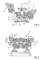
- Fig. 2
- eine geschnittene Seitenansicht der erfindungsgemäßen Spanneinrichtung gemäß Ebene II aus
Fig. 1 , teilweise in Explosionsdarstellung, - Fig. 3
- eine geschnittene Seitenansicht der erfindungsgemäßen Spanneinrichtung gemäß Ebene II in
Fig. 1 , in einem Montagezustand, - Fig. 4a
- eine geschnittene Seitenansicht der erfindungsgemäßen Spanneinrichtung gemäß Ebene II in
Fig. 1 , - Fig. 4b
- eine geschnittene Seitenansicht der erfindungsgemäßen Spanneinrichtung gemäß Ebene I der
Fig. 1 , - Fig. 5
- eine isometrische Ansicht der erfindungsgemäßen Spanneinrichtung gemäß einer zweiten Ausführungsform, montiert auf einem Adapter,
- Fig. 6
- eine isometrische Ansicht der erfindungsgemäßen Spanneinrichtung gemäß einer dritten Ausführungsform, montiert auf einem Adapter,
- Fig. 7
- eine isometrische Ansicht der erfindungsgemäßen Spanneinrichtung gemäß einer vierten Ausführungsform, montiert auf einem Adapter, sowie
- Fig. 8
- eine isometrische Ansicht der erfindungsgemäßen Spanneinrichtung gemäß einer fünften Ausführungsform, montiert auf einem Adapter.
- Fig. 1
- an isometric view in part cutaway of a first embodiment of the clamping device according to the invention mounted on an adapter,
- Fig. 2
- a sectional side view of the clamping device according to the invention according to level II
Fig. 1 , partially exploded, - Fig. 3
- a sectional side view of the clamping device according to the invention according to level II in
Fig. 1 in an assembled condition, - Fig. 4a
- a sectional side view of the clamping device according to the invention according to level II in
Fig. 1 . - Fig. 4b
- a sectional side view of the clamping device according to the invention according to level I of
Fig. 1 . - Fig. 5
- an isometric view of the clamping device according to the invention according to a second embodiment, mounted on an adapter,
- Fig. 6
- an isometric view of the clamping device according to the invention according to a third embodiment, mounted on an adapter,
- Fig. 7
- an isometric view of the clamping device according to the invention according to a fourth embodiment, mounted on an adapter, and
- Fig. 8
- an isometric view of the clamping device according to the invention according to a fifth embodiment, mounted on an adapter.
Die
Die Spannelementaufnahmen 14 sind in einem Grundkörper 20 der Spanneinrichtung 10 vorgesehen. Die Spannelementaufnahmen 14 sind so ausgebildet, dass die Spannelemente 12 in und entgegengesetzt einer Spannrichtung 22 bewegbar sind. Der Grundkörper 20 weist eine zentrale Ausnehmung 24 auf, in der unter anderem ein erstes Kuppelteil 26 sowie ein zweites Kuppelteil 28 zur Bildung einer Kupplung 30 angeordnet sind. Die zentrale Ausnehmung 24 ist gemäß
Die Spanneinrichtung 10 ist auf einem Adapter 36 montiert. Der Adapter 36 weist adapterseitige Bajonettverschlussabschnitte 38a und 38b auf, die mit dem ersten Kuppelteil 26 bzw. dem zweiten Kuppelteil 28 in Eingriff stehen. Hierzu weisen die Kuppelteile 26, 28 spanneinrichtungsseitige Bajonettverschlussteile 40a und 40b auf.The
In der gemäß Ebene II der
In der gemäß Ebene II der
Anschließend wird die Spannbacke 16 um eine Achse verschwenkt, die im Bereich der Hinterschnittverbindung 52 angeordnet ist, so dass die Spannbacke 16 in die im rechten Bereich der
Die
Durch diese paarweise Verbindung der Spannelemente 12 mittels des entsprechenden Kuppelteils 26, 28 und der Verbindung der Kuppelteile 26, 28 jeweils mit einem adapterseitigen Bajonettverschlussabschnitt 38 können die Spannelemente 12 jeweils paarweise und aufeinanderfolgend zum Erzeugen einer Spannwirkung bzw. beispielsweise zum Lösen der Spannwirkung bewegt werden. Selbstverständlich können die adapterseitigen Bajonettverschlussabschnittsteile 38 auch miteinander gekoppelt werden, so dass alle Spannelemente 12 gleichzeitig bewegt werden können.By this pairwise connection of the clamping
In der
Eine alternative Möglichkeit der Ausgestaltung von Spannelementen 12 der erfindungsgemäßen Spanneinrichtung 10 ist in
In
Claims (15)
Applications Claiming Priority (1)
| Application Number | Priority Date | Filing Date | Title |
|---|---|---|---|
| DE102008064525A DE102008064525A1 (en) | 2008-12-18 | 2008-12-18 | Clamping device and method for connecting a clamping jaw with a clamping device |
Publications (2)
| Publication Number | Publication Date |
|---|---|
| EP2198995A1 true EP2198995A1 (en) | 2010-06-23 |
| EP2198995B1 EP2198995B1 (en) | 2012-07-04 |
Family
ID=41809168
Family Applications (1)
| Application Number | Title | Priority Date | Filing Date |
|---|---|---|---|
| EP09179602A Not-in-force EP2198995B1 (en) | 2008-12-18 | 2009-12-17 | Clamp and method for connecting clamping jaws to a clamp |
Country Status (4)
| Country | Link |
|---|---|
| US (1) | US8408528B2 (en) |
| EP (1) | EP2198995B1 (en) |
| CA (1) | CA2687705C (en) |
| DE (1) | DE102008064525A1 (en) |
Families Citing this family (3)
| Publication number | Priority date | Publication date | Assignee | Title |
|---|---|---|---|---|
| DE102016010747A1 (en) | 2016-09-06 | 2018-03-08 | EMAG GmbH & Co. KG | Plan chuck |
| CN113635103B (en) * | 2021-10-14 | 2021-12-10 | 斯得浦泵业南通有限公司 | Clamping device of numerical control machine tool |
| CN115302423B (en) * | 2022-10-11 | 2023-03-24 | 烟台台芯电子科技有限公司 | IGBT module DBC aluminum wire bonding tool |
Citations (5)
| Publication number | Priority date | Publication date | Assignee | Title |
|---|---|---|---|---|
| US2464625A (en) * | 1944-12-30 | 1949-03-15 | Lees Bradner Co | Holding device |
| FR2119685A5 (en) * | 1970-12-24 | 1972-08-04 | Morawski London | |
| CA962826A (en) * | 1970-12-24 | 1975-02-18 | London T. Morawski | Multi-jaw chuck |
| US6012712A (en) * | 1998-03-20 | 2000-01-11 | Kurt Manufacturing Company, Inc. | Double vise with self-setting clamping with the same or different size workpieces |
| EP1704010A1 (en) * | 2004-01-07 | 2006-09-27 | Hainbuch Gmbh Spannende Technik | Clamping device |
Family Cites Families (11)
| Publication number | Priority date | Publication date | Assignee | Title |
|---|---|---|---|---|
| US2680395A (en) * | 1949-10-29 | 1954-06-08 | Erwood B Christiansen | Vise with split adjustable jaws |
| DE889880C (en) * | 1952-05-06 | 1953-09-14 | Eugen Bauckhage | Jaws, especially for vices |
| FR1129058A (en) | 1955-06-07 | 1957-01-15 | Prec Ind | Machining chuck and its operating mechanism |
| US4114910A (en) * | 1977-04-19 | 1978-09-19 | Reeder Marion F | Lathe chuck assembly for holding universal joints |
| US4530508A (en) * | 1982-07-14 | 1985-07-23 | Ferraro Thomas A | Jaw locking means for lathe chucks |
| US5149071A (en) * | 1991-11-04 | 1992-09-22 | Oliveira Paul L | Double-jaw vice for holding workpieces |
| US5464231A (en) * | 1994-06-20 | 1995-11-07 | Clay; Tymen | Chuck with jaws having curved engagement surfaces |
| US20050218608A1 (en) * | 2002-05-02 | 2005-10-06 | Johann Taglang | Clamping chuck |
| DE602004006600T2 (en) * | 2004-03-18 | 2008-01-31 | Tesa Sa | Tool changing device |
| DE102005018655A1 (en) * | 2005-04-21 | 2006-10-26 | Cnc-Service Egger | jig |
| CA2558910A1 (en) * | 2005-09-07 | 2007-03-07 | Hardinge Inc. | Workholding clamping assembly |
-
2008
- 2008-12-18 DE DE102008064525A patent/DE102008064525A1/en not_active Withdrawn
-
2009
- 2009-12-08 CA CA2687705A patent/CA2687705C/en not_active Expired - Fee Related
- 2009-12-17 US US12/640,924 patent/US8408528B2/en not_active Expired - Fee Related
- 2009-12-17 EP EP09179602A patent/EP2198995B1/en not_active Not-in-force
Patent Citations (5)
| Publication number | Priority date | Publication date | Assignee | Title |
|---|---|---|---|---|
| US2464625A (en) * | 1944-12-30 | 1949-03-15 | Lees Bradner Co | Holding device |
| FR2119685A5 (en) * | 1970-12-24 | 1972-08-04 | Morawski London | |
| CA962826A (en) * | 1970-12-24 | 1975-02-18 | London T. Morawski | Multi-jaw chuck |
| US6012712A (en) * | 1998-03-20 | 2000-01-11 | Kurt Manufacturing Company, Inc. | Double vise with self-setting clamping with the same or different size workpieces |
| EP1704010A1 (en) * | 2004-01-07 | 2006-09-27 | Hainbuch Gmbh Spannende Technik | Clamping device |
Also Published As
| Publication number | Publication date |
|---|---|
| CA2687705C (en) | 2016-08-09 |
| DE102008064525A1 (en) | 2010-07-01 |
| CA2687705A1 (en) | 2010-06-18 |
| US8408528B2 (en) | 2013-04-02 |
| US20100156016A1 (en) | 2010-06-24 |
| EP2198995B1 (en) | 2012-07-04 |
Similar Documents
| Publication | Publication Date | Title |
|---|---|---|
| DE102015218523B4 (en) | Gripping device | |
| EP2463969B1 (en) | Plier head for crimping pliers | |
| EP0868978A1 (en) | Crimping tool for crimping a workpiece | |
| DE102009005983A1 (en) | Pipe processing device | |
| EP2965843B1 (en) | Collet chuck and clamping means with quick change function | |
| EP1809441B1 (en) | Tensioning or gripping device in particular a linear or centering gripper | |
| DE202013101917U1 (en) | chuck | |
| DE102005031802A1 (en) | Tool receiver for machine tool has at least one fixing element to lock fork elements in tool receiving position | |
| DE202011052206U1 (en) | Basic body for a robot welding gun | |
| DE102016218298B4 (en) | gripping device | |
| EP1038617A2 (en) | Toolholder and machine tool | |
| WO1994005451A1 (en) | Clamping device for connecting machine spindles to tool holders | |
| EP3766640A1 (en) | Magnetic base | |
| DE102004029051B3 (en) | Fixing device for jaw of grip has receiver for fixing bolts for one of jaws, with locking bolts having eccentric contact sector | |
| EP2198995B1 (en) | Clamp and method for connecting clamping jaws to a clamp | |
| EP0275441B1 (en) | Clamping device | |
| DE102013212744B4 (en) | Nozzle holder, nozzle changer and laser processing machine | |
| EP0391085B1 (en) | Device for changing and clamping tools | |
| EP3386678A1 (en) | Device for the automated coupling and decoupling of a tool attachment, as well as method for the automated connection of at least two workpieces | |
| EP2357690A1 (en) | Battery pack and electric device having three dimensional coding system | |
| DE102016107648B3 (en) | Milling machine with a clamping device for a workpiece a positionally stable clamping frame | |
| DE102017117961B4 (en) | Method and device for preparing screws | |
| DE102015012938A1 (en) | The restraint | |
| DE202007012284U1 (en) | Surgical retractor | |
| DE102019106395B3 (en) | Hinge and method for making and releasing a releasable hinge connection between a door and a frame |
Legal Events
| Date | Code | Title | Description |
|---|---|---|---|
| PUAI | Public reference made under article 153(3) epc to a published international application that has entered the european phase |
Free format text: ORIGINAL CODE: 0009012 |
|
| AK | Designated contracting states |
Kind code of ref document: A1 Designated state(s): AT BE BG CH CY CZ DE DK EE ES FI FR GB GR HR HU IE IS IT LI LT LU LV MC MK MT NL NO PL PT RO SE SI SK SM TR |
|
| AX | Request for extension of the european patent |
Extension state: AL BA RS |
|
| 17P | Request for examination filed |
Effective date: 20101217 |
|
| GRAP | Despatch of communication of intention to grant a patent |
Free format text: ORIGINAL CODE: EPIDOSNIGR1 |
|
| GRAS | Grant fee paid |
Free format text: ORIGINAL CODE: EPIDOSNIGR3 |
|
| GRAA | (expected) grant |
Free format text: ORIGINAL CODE: 0009210 |
|
| AK | Designated contracting states |
Kind code of ref document: B1 Designated state(s): AT BE BG CH CY CZ DE DK EE ES FI FR GB GR HR HU IE IS IT LI LT LU LV MC MK MT NL NO PL PT RO SE SI SK SM TR |
|
| REG | Reference to a national code |
Ref country code: GB Ref legal event code: FG4D Free format text: NOT ENGLISH |
|
| REG | Reference to a national code |
Ref country code: CH Ref legal event code: EP |
|
| REG | Reference to a national code |
Ref country code: AT Ref legal event code: REF Ref document number: 564949 Country of ref document: AT Kind code of ref document: T Effective date: 20120715 |
|
| REG | Reference to a national code |
Ref country code: IE Ref legal event code: FG4D Free format text: LANGUAGE OF EP DOCUMENT: GERMAN |
|
| REG | Reference to a national code |
Ref country code: DE Ref legal event code: R096 Ref document number: 502009003998 Country of ref document: DE Effective date: 20120830 |
|
| REG | Reference to a national code |
Ref country code: CH Ref legal event code: NV Representative=s name: ZIMMERLI, WAGNER & PARTNER AG |
|
| REG | Reference to a national code |
Ref country code: NL Ref legal event code: VDEP Effective date: 20120704 |
|
| PG25 | Lapsed in a contracting state [announced via postgrant information from national office to epo] |
Ref country code: SI Free format text: LAPSE BECAUSE OF FAILURE TO SUBMIT A TRANSLATION OF THE DESCRIPTION OR TO PAY THE FEE WITHIN THE PRESCRIBED TIME-LIMIT Effective date: 20120704 |
|
| REG | Reference to a national code |
Ref country code: LT Ref legal event code: MG4D Effective date: 20120704 |
|
| PG25 | Lapsed in a contracting state [announced via postgrant information from national office to epo] |
Ref country code: HR Free format text: LAPSE BECAUSE OF FAILURE TO SUBMIT A TRANSLATION OF THE DESCRIPTION OR TO PAY THE FEE WITHIN THE PRESCRIBED TIME-LIMIT Effective date: 20120704 Ref country code: FI Free format text: LAPSE BECAUSE OF FAILURE TO SUBMIT A TRANSLATION OF THE DESCRIPTION OR TO PAY THE FEE WITHIN THE PRESCRIBED TIME-LIMIT Effective date: 20120704 Ref country code: IS Free format text: LAPSE BECAUSE OF FAILURE TO SUBMIT A TRANSLATION OF THE DESCRIPTION OR TO PAY THE FEE WITHIN THE PRESCRIBED TIME-LIMIT Effective date: 20121104 Ref country code: CY Free format text: LAPSE BECAUSE OF FAILURE TO SUBMIT A TRANSLATION OF THE DESCRIPTION OR TO PAY THE FEE WITHIN THE PRESCRIBED TIME-LIMIT Effective date: 20120704 Ref country code: NO Free format text: LAPSE BECAUSE OF FAILURE TO SUBMIT A TRANSLATION OF THE DESCRIPTION OR TO PAY THE FEE WITHIN THE PRESCRIBED TIME-LIMIT Effective date: 20121004 Ref country code: LT Free format text: LAPSE BECAUSE OF FAILURE TO SUBMIT A TRANSLATION OF THE DESCRIPTION OR TO PAY THE FEE WITHIN THE PRESCRIBED TIME-LIMIT Effective date: 20120704 |
|
| PG25 | Lapsed in a contracting state [announced via postgrant information from national office to epo] |
Ref country code: PL Free format text: LAPSE BECAUSE OF FAILURE TO SUBMIT A TRANSLATION OF THE DESCRIPTION OR TO PAY THE FEE WITHIN THE PRESCRIBED TIME-LIMIT Effective date: 20120704 Ref country code: PT Free format text: LAPSE BECAUSE OF FAILURE TO SUBMIT A TRANSLATION OF THE DESCRIPTION OR TO PAY THE FEE WITHIN THE PRESCRIBED TIME-LIMIT Effective date: 20121105 Ref country code: SE Free format text: LAPSE BECAUSE OF FAILURE TO SUBMIT A TRANSLATION OF THE DESCRIPTION OR TO PAY THE FEE WITHIN THE PRESCRIBED TIME-LIMIT Effective date: 20120704 Ref country code: GR Free format text: LAPSE BECAUSE OF FAILURE TO SUBMIT A TRANSLATION OF THE DESCRIPTION OR TO PAY THE FEE WITHIN THE PRESCRIBED TIME-LIMIT Effective date: 20121005 Ref country code: LV Free format text: LAPSE BECAUSE OF FAILURE TO SUBMIT A TRANSLATION OF THE DESCRIPTION OR TO PAY THE FEE WITHIN THE PRESCRIBED TIME-LIMIT Effective date: 20120704 |
|
| PG25 | Lapsed in a contracting state [announced via postgrant information from national office to epo] |
Ref country code: NL Free format text: LAPSE BECAUSE OF FAILURE TO SUBMIT A TRANSLATION OF THE DESCRIPTION OR TO PAY THE FEE WITHIN THE PRESCRIBED TIME-LIMIT Effective date: 20120704 |
|
| PG25 | Lapsed in a contracting state [announced via postgrant information from national office to epo] |
Ref country code: CZ Free format text: LAPSE BECAUSE OF FAILURE TO SUBMIT A TRANSLATION OF THE DESCRIPTION OR TO PAY THE FEE WITHIN THE PRESCRIBED TIME-LIMIT Effective date: 20120704 Ref country code: DK Free format text: LAPSE BECAUSE OF FAILURE TO SUBMIT A TRANSLATION OF THE DESCRIPTION OR TO PAY THE FEE WITHIN THE PRESCRIBED TIME-LIMIT Effective date: 20120704 Ref country code: RO Free format text: LAPSE BECAUSE OF FAILURE TO SUBMIT A TRANSLATION OF THE DESCRIPTION OR TO PAY THE FEE WITHIN THE PRESCRIBED TIME-LIMIT Effective date: 20120704 Ref country code: EE Free format text: LAPSE BECAUSE OF FAILURE TO SUBMIT A TRANSLATION OF THE DESCRIPTION OR TO PAY THE FEE WITHIN THE PRESCRIBED TIME-LIMIT Effective date: 20120704 |
|
| PLBE | No opposition filed within time limit |
Free format text: ORIGINAL CODE: 0009261 |
|
| STAA | Information on the status of an ep patent application or granted ep patent |
Free format text: STATUS: NO OPPOSITION FILED WITHIN TIME LIMIT |
|
| PG25 | Lapsed in a contracting state [announced via postgrant information from national office to epo] |
Ref country code: SK Free format text: LAPSE BECAUSE OF FAILURE TO SUBMIT A TRANSLATION OF THE DESCRIPTION OR TO PAY THE FEE WITHIN THE PRESCRIBED TIME-LIMIT Effective date: 20120704 |
|
| 26N | No opposition filed |
Effective date: 20130405 |
|
| BERE | Be: lapsed |
Owner name: HAINBUCH G.M.B.H. SPANNENDE TECHNIK Effective date: 20121231 |
|
| PG25 | Lapsed in a contracting state [announced via postgrant information from national office to epo] |
Ref country code: MC Free format text: LAPSE BECAUSE OF NON-PAYMENT OF DUE FEES Effective date: 20121231 Ref country code: BG Free format text: LAPSE BECAUSE OF FAILURE TO SUBMIT A TRANSLATION OF THE DESCRIPTION OR TO PAY THE FEE WITHIN THE PRESCRIBED TIME-LIMIT Effective date: 20121004 |
|
| REG | Reference to a national code |
Ref country code: DE Ref legal event code: R097 Ref document number: 502009003998 Country of ref document: DE Effective date: 20130405 |
|
| REG | Reference to a national code |
Ref country code: IE Ref legal event code: MM4A |
|
| PG25 | Lapsed in a contracting state [announced via postgrant information from national office to epo] |
Ref country code: BE Free format text: LAPSE BECAUSE OF NON-PAYMENT OF DUE FEES Effective date: 20121231 |
|
| PG25 | Lapsed in a contracting state [announced via postgrant information from national office to epo] |
Ref country code: ES Free format text: LAPSE BECAUSE OF FAILURE TO SUBMIT A TRANSLATION OF THE DESCRIPTION OR TO PAY THE FEE WITHIN THE PRESCRIBED TIME-LIMIT Effective date: 20121015 Ref country code: IE Free format text: LAPSE BECAUSE OF NON-PAYMENT OF DUE FEES Effective date: 20121217 |
|
| PG25 | Lapsed in a contracting state [announced via postgrant information from national office to epo] |
Ref country code: MT Free format text: LAPSE BECAUSE OF FAILURE TO SUBMIT A TRANSLATION OF THE DESCRIPTION OR TO PAY THE FEE WITHIN THE PRESCRIBED TIME-LIMIT Effective date: 20120704 |
|
| REG | Reference to a national code |
Ref country code: CH Ref legal event code: NV Representative=s name: WAGNER PATENT AG, CH |
|
| PG25 | Lapsed in a contracting state [announced via postgrant information from national office to epo] |
Ref country code: TR Free format text: LAPSE BECAUSE OF FAILURE TO SUBMIT A TRANSLATION OF THE DESCRIPTION OR TO PAY THE FEE WITHIN THE PRESCRIBED TIME-LIMIT Effective date: 20120704 |
|
| PG25 | Lapsed in a contracting state [announced via postgrant information from national office to epo] |
Ref country code: SM Free format text: LAPSE BECAUSE OF FAILURE TO SUBMIT A TRANSLATION OF THE DESCRIPTION OR TO PAY THE FEE WITHIN THE PRESCRIBED TIME-LIMIT Effective date: 20120704 Ref country code: LU Free format text: LAPSE BECAUSE OF NON-PAYMENT OF DUE FEES Effective date: 20121217 |
|
| PG25 | Lapsed in a contracting state [announced via postgrant information from national office to epo] |
Ref country code: HU Free format text: LAPSE BECAUSE OF FAILURE TO SUBMIT A TRANSLATION OF THE DESCRIPTION OR TO PAY THE FEE WITHIN THE PRESCRIBED TIME-LIMIT Effective date: 20091217 |
|
| PG25 | Lapsed in a contracting state [announced via postgrant information from national office to epo] |
Ref country code: MK Free format text: LAPSE BECAUSE OF FAILURE TO SUBMIT A TRANSLATION OF THE DESCRIPTION OR TO PAY THE FEE WITHIN THE PRESCRIBED TIME-LIMIT Effective date: 20120704 |
|
| REG | Reference to a national code |
Ref country code: FR Ref legal event code: PLFP Year of fee payment: 7 |
|
| REG | Reference to a national code |
Ref country code: DE Ref legal event code: R082 Ref document number: 502009003998 Country of ref document: DE Representative=s name: PATENTANWALTSKANZLEI CARTAGENA PARTNERSCHAFTSG, DE |
|
| REG | Reference to a national code |
Ref country code: FR Ref legal event code: PLFP Year of fee payment: 8 |
|
| REG | Reference to a national code |
Ref country code: FR Ref legal event code: PLFP Year of fee payment: 9 |
|
| PGFP | Annual fee paid to national office [announced via postgrant information from national office to epo] |
Ref country code: DE Payment date: 20191218 Year of fee payment: 11 |
|
| PGFP | Annual fee paid to national office [announced via postgrant information from national office to epo] |
Ref country code: FR Payment date: 20191219 Year of fee payment: 11 Ref country code: IT Payment date: 20191216 Year of fee payment: 11 |
|
| PGFP | Annual fee paid to national office [announced via postgrant information from national office to epo] |
Ref country code: AT Payment date: 20191213 Year of fee payment: 11 Ref country code: CH Payment date: 20191220 Year of fee payment: 11 |
|
| PGFP | Annual fee paid to national office [announced via postgrant information from national office to epo] |
Ref country code: GB Payment date: 20191220 Year of fee payment: 11 |
|
| REG | Reference to a national code |
Ref country code: DE Ref legal event code: R119 Ref document number: 502009003998 Country of ref document: DE |
|
| REG | Reference to a national code |
Ref country code: CH Ref legal event code: PL |
|
| REG | Reference to a national code |
Ref country code: AT Ref legal event code: MM01 Ref document number: 564949 Country of ref document: AT Kind code of ref document: T Effective date: 20201217 |
|
| GBPC | Gb: european patent ceased through non-payment of renewal fee |
Effective date: 20201217 |
|
| PG25 | Lapsed in a contracting state [announced via postgrant information from national office to epo] |
Ref country code: AT Free format text: LAPSE BECAUSE OF NON-PAYMENT OF DUE FEES Effective date: 20201217 Ref country code: IT Free format text: LAPSE BECAUSE OF NON-PAYMENT OF DUE FEES Effective date: 20201217 Ref country code: FR Free format text: LAPSE BECAUSE OF NON-PAYMENT OF DUE FEES Effective date: 20201231 |
|
| PG25 | Lapsed in a contracting state [announced via postgrant information from national office to epo] |
Ref country code: LI Free format text: LAPSE BECAUSE OF NON-PAYMENT OF DUE FEES Effective date: 20201231 Ref country code: GB Free format text: LAPSE BECAUSE OF NON-PAYMENT OF DUE FEES Effective date: 20201217 Ref country code: CH Free format text: LAPSE BECAUSE OF NON-PAYMENT OF DUE FEES Effective date: 20201231 Ref country code: DE Free format text: LAPSE BECAUSE OF NON-PAYMENT OF DUE FEES Effective date: 20210701 |