EP2197566B1 - Method and system for regenerating an amine-containing wash solution obtained during gas purification - Google Patents
Method and system for regenerating an amine-containing wash solution obtained during gas purification Download PDFInfo
- Publication number
- EP2197566B1 EP2197566B1 EP08785494A EP08785494A EP2197566B1 EP 2197566 B1 EP2197566 B1 EP 2197566B1 EP 08785494 A EP08785494 A EP 08785494A EP 08785494 A EP08785494 A EP 08785494A EP 2197566 B1 EP2197566 B1 EP 2197566B1
- Authority
- EP
- European Patent Office
- Prior art keywords
- scrubbing solution
- expansion
- line
- expansion stage
- pressure
- Prior art date
- Legal status (The legal status is an assumption and is not a legal conclusion. Google has not performed a legal analysis and makes no representation as to the accuracy of the status listed.)
- Active
Links
- 238000000034 method Methods 0.000 title claims abstract description 39
- 150000001412 amines Chemical class 0.000 title claims abstract description 13
- 238000000746 purification Methods 0.000 title claims abstract description 6
- 230000001172 regenerating effect Effects 0.000 title claims abstract description 4
- 238000005201 scrubbing Methods 0.000 claims abstract description 42
- 150000003464 sulfur compounds Chemical class 0.000 claims abstract description 34
- CURLTUGMZLYLDI-UHFFFAOYSA-N Carbon dioxide Chemical compound O=C=O CURLTUGMZLYLDI-UHFFFAOYSA-N 0.000 claims description 26
- 239000007789 gas Substances 0.000 claims description 25
- XLYOFNOQVPJJNP-UHFFFAOYSA-N water Substances O XLYOFNOQVPJJNP-UHFFFAOYSA-N 0.000 claims description 22
- 229910001868 water Inorganic materials 0.000 claims description 22
- 229910002092 carbon dioxide Inorganic materials 0.000 claims description 15
- 239000001569 carbon dioxide Substances 0.000 claims description 11
- 238000010438 heat treatment Methods 0.000 claims description 7
- 239000012535 impurity Substances 0.000 claims description 6
- 239000000203 mixture Substances 0.000 claims description 6
- 238000001816 cooling Methods 0.000 claims description 3
- 238000011084 recovery Methods 0.000 claims description 3
- VUZPPFZMUPKLLV-UHFFFAOYSA-N methane;hydrate Chemical compound C.O VUZPPFZMUPKLLV-UHFFFAOYSA-N 0.000 claims description 2
- 238000006477 desulfuration reaction Methods 0.000 claims 1
- 230000023556 desulfurization Effects 0.000 claims 1
- 238000009210 therapy by ultrasound Methods 0.000 claims 1
- 238000011144 upstream manufacturing Methods 0.000 claims 1
- 239000002918 waste heat Substances 0.000 claims 1
- 238000005406 washing Methods 0.000 description 39
- 230000008929 regeneration Effects 0.000 description 8
- 238000011069 regeneration method Methods 0.000 description 8
- 239000003599 detergent Substances 0.000 description 7
- VNWKTOKETHGBQD-UHFFFAOYSA-N methane Chemical compound C VNWKTOKETHGBQD-UHFFFAOYSA-N 0.000 description 6
- 238000000926 separation method Methods 0.000 description 5
- 239000000498 cooling water Substances 0.000 description 3
- 229930195733 hydrocarbon Natural products 0.000 description 3
- 150000002430 hydrocarbons Chemical class 0.000 description 3
- 238000011068 loading method Methods 0.000 description 3
- 239000000126 substance Substances 0.000 description 3
- 238000006243 chemical reaction Methods 0.000 description 2
- 230000008030 elimination Effects 0.000 description 2
- 238000003379 elimination reaction Methods 0.000 description 2
- 238000005265 energy consumption Methods 0.000 description 2
- 230000035484 reaction time Effects 0.000 description 2
- 239000002904 solvent Substances 0.000 description 2
- 238000010521 absorption reaction Methods 0.000 description 1
- 230000002411 adverse Effects 0.000 description 1
- -1 biogas Substances 0.000 description 1
- 238000001311 chemical methods and process Methods 0.000 description 1
- 238000004891 communication Methods 0.000 description 1
- 238000009833 condensation Methods 0.000 description 1
- 230000005494 condensation Effects 0.000 description 1
- 238000000354 decomposition reaction Methods 0.000 description 1
- 230000008021 deposition Effects 0.000 description 1
- 238000003795 desorption Methods 0.000 description 1
- 238000011161 development Methods 0.000 description 1
- 230000018109 developmental process Effects 0.000 description 1
- 238000010586 diagram Methods 0.000 description 1
- 230000000694 effects Effects 0.000 description 1
- 239000007788 liquid Substances 0.000 description 1
- 238000004519 manufacturing process Methods 0.000 description 1
- 150000002898 organic sulfur compounds Chemical class 0.000 description 1
- 230000000717 retained effect Effects 0.000 description 1
- 238000009834 vaporization Methods 0.000 description 1
- 230000008016 vaporization Effects 0.000 description 1
- 239000002912 waste gas Substances 0.000 description 1
Images
Classifications
-
- B—PERFORMING OPERATIONS; TRANSPORTING
- B01—PHYSICAL OR CHEMICAL PROCESSES OR APPARATUS IN GENERAL
- B01D—SEPARATION
- B01D53/00—Separation of gases or vapours; Recovering vapours of volatile solvents from gases; Chemical or biological purification of waste gases, e.g. engine exhaust gases, smoke, fumes, flue gases, aerosols
- B01D53/14—Separation of gases or vapours; Recovering vapours of volatile solvents from gases; Chemical or biological purification of waste gases, e.g. engine exhaust gases, smoke, fumes, flue gases, aerosols by absorption
- B01D53/1425—Regeneration of liquid absorbents
-
- B—PERFORMING OPERATIONS; TRANSPORTING
- B01—PHYSICAL OR CHEMICAL PROCESSES OR APPARATUS IN GENERAL
- B01D—SEPARATION
- B01D53/00—Separation of gases or vapours; Recovering vapours of volatile solvents from gases; Chemical or biological purification of waste gases, e.g. engine exhaust gases, smoke, fumes, flue gases, aerosols
- B01D53/14—Separation of gases or vapours; Recovering vapours of volatile solvents from gases; Chemical or biological purification of waste gases, e.g. engine exhaust gases, smoke, fumes, flue gases, aerosols by absorption
- B01D53/1456—Removing acid components
-
- B—PERFORMING OPERATIONS; TRANSPORTING
- B01—PHYSICAL OR CHEMICAL PROCESSES OR APPARATUS IN GENERAL
- B01D—SEPARATION
- B01D2257/00—Components to be removed
- B01D2257/30—Sulfur compounds
- B01D2257/304—Hydrogen sulfide
-
- B—PERFORMING OPERATIONS; TRANSPORTING
- B01—PHYSICAL OR CHEMICAL PROCESSES OR APPARATUS IN GENERAL
- B01D—SEPARATION
- B01D2257/00—Components to be removed
- B01D2257/30—Sulfur compounds
- B01D2257/308—Carbonoxysulfide COS
-
- B—PERFORMING OPERATIONS; TRANSPORTING
- B01—PHYSICAL OR CHEMICAL PROCESSES OR APPARATUS IN GENERAL
- B01D—SEPARATION
- B01D2257/00—Components to be removed
- B01D2257/50—Carbon oxides
- B01D2257/504—Carbon dioxide
-
- B—PERFORMING OPERATIONS; TRANSPORTING
- B01—PHYSICAL OR CHEMICAL PROCESSES OR APPARATUS IN GENERAL
- B01D—SEPARATION
- B01D2258/00—Sources of waste gases
- B01D2258/05—Biogas
Definitions
- the invention relates to a process for the regeneration of an amine-containing scrubbing solution obtained in the purification of gases, in which CO 2 and sulfur compounds are chemically bound, and to a plant suitable for carrying out the process.
- gases such as biogas, waste gases from chemical processes, refinery gas or associated gas, contain CO 2 and sulfur compounds, which must be removed before further use or discharge of these gases into the atmosphere by means of a laundry from these.
- physical or chemical gas scrubbing are used, wherein a chemical scrubbing is preferably carried out by means of an amine-containing scrubbing solution in which separated CO 2 and sulfur compounds are chemically bonded.
- it is useful to regenerate the contaminated amine-containing wash solution so that it can be recycled for reuse.
- the disadvantages are the high operating pressure and the high temperatures. The latter leads to losses of washing solution and increases the risk of decomposition.
- the purified wash solution still contains small amounts of impurities which have an adverse effect on reuse.
- WO 2004/052511 A discloses the regeneration of a physical solvent in a series of flash stages.
- WO 2005/044355 A discloses the regeneration of a solvent in a high pressure flash column and in another flash column or series of flash columns.
- the invention has for its object to provide a method for regenerating a resulting in the purification of gases amine-containing wash solution in which CO 2 and sulfur compounds are chemically bonded, which allows a more economical operation and with which a high-purity wash solution is obtained.
- the contaminated washing solution is heated to a temperature of at least 110 ° C, optionally to 135 ° C, preferably 125 ° C, and compressed to a pressure of at least 4 bar, preferably 6 to 12 bar, and subsequently expanded in a first expansion stage, preferably to a pressure of 1 to 8 bar, wherein the majority of CO 2 and sulfur compounds is separated as a gas stream from the washing solution (process step a)).
- the withdrawn washing solution is heated to a temperature of at least 130 ° C, optionally to 160 ° C, preferably 145 ° C, and to a pressure of at least 4 bar, preferably 5 to 8 bar, compressed and in a second expansion stage to a pressure relaxed, which is at least 0.5 bar, optionally up to 3 bar, higher than the expansion pressure of the first expansion stage, wherein the majority of remaining CO 2 and sulfur compounds is separated as a gas stream from the washing solution (process step b)).
- the expansion is preferably carried out as flash relaxation.
- the scrubbing solution withdrawn from the second expansion stage is cooled to a temperature below 70 ° C. and depressurized to atmospheric pressure in a third expansion stage, residual amounts of soluble CO 2 still remaining being removed and this substream is cooled to a normal temperature as a completely purified scrubbing solution ( Process step c)).
- the scrubbing solution withdrawn after the first expansion stage and / or second expansion stage is divided into two sub-streams.
- a partial flow is recirculated to the respective expansion stage and adjusted in terms of temperature and pressure to the conditions of the associated expansion stage. During the expansion remaining residual amounts of sulfur compounds are separated from this partial flow.
- the other part of the uncirculated stream is treated further either after process step b) or c).
- the stripped washing solution is compressed, for example to a pressure of 5 to 10 bar and heated to a temperature which is at least 2 to 10 ° C higher than the operating temperature in the respective expansion stage.
- the proposed procedure allows a regeneration of the contaminated washing solution with differently loaded substances at comparatively low pressures and temperatures, due to the envisaged multi-stage pressure and temperature-controlled relaxation.
- the proportion of water contained in the washing solution is retained, as are removed by means of the vapors discharged amounts of vaporized water after condensation again the purified washing solution.
- the multi-stage expansion of the contaminated wash solution allows a more selective separation of CO 2 , H 2 S and COS (organic sulfur compounds). Due to the different pressure and temperature conditions, the amount of water escaping from the wash solution at the individual flash releases can be significantly reduced. Since water has a higher heat of vaporization by a factor of 5 than the components to be removed from the gases, the required energy input for the necessary regeneration can thus be considerably reduced.
- the gas mixture of carbon dioxide, water and sulfur compounds withdrawn as vapors in the expansion stages according to process steps a) and b) is used as a heat carrier to heat the contaminated washing solution and cooled down to normal temperature.
- the resulting in the second expansion stage purified scrubbing solution is used as a heat carrier for heating the contaminated scrubbing solution.
- the gas stream (CO 2 and sulfur compounds) removed from the first and second expansion stages can be desulfurized in a downstream desulphurisation plant.
- reaction times in the first expansion stage can be further reduced by sonicating the wash solution.
- the dwell time or reaction time in this stage can thus be reduced by up to about 30% for the same deposition result.
- the second expansion stage can be followed by the same procedure still a third or fourth relaxation stage.
- the pH of the purified wash solution can be measured and serves as a controlled variable for adjusting the temperature of the contaminated wash solution in the expansion stages.
- the ratio between the amount of partial flow swept out and the amount of contaminated wash solution supplied is from 0.2 to 5.
- the intended elimination of a partial amount of washing solution in the first and / or second expansion stage has the following advantages.
- the partial flow amount, the pressure and the temperature of the partial flow circuit can be further adapted to the amounts of sulfur compounds contained in the biogas and used as a controlled variable.
- the adjusting working capacity of this washing solution is up to more than 85 g / l with respect to the separation of carbon dioxide and up to more than 15 g / l with sulfur compounds.
- smaller quantities of hydrocarbons are dissolved in the washing water with the smaller amount of detergent.
- methane losses are thus in the range of less than 0.05%. Using less detergent reduces energy consumption.
- a system suitable for carrying out the method comprises a circulation line for guiding the washing solution, in which a first pump, at least one heat exchanger, at least two expansion devices connected in series and a first separator are integrated in the flow direction. Between the first and the second expansion device, a second pump and a downstream heat exchanger are integrated into the circulation line. After at least one of the expansion devices branches from the circulation line from a loop of tubing, which is in communication with the expansion device, for the elimination of a partial amount of purified washing solution and their return to the expansion device. In the line loop, a third pump and a further heat exchanger are integrated.
- a conduit for the removal of the vapors is arranged, which communicates with a second separator for the separation of the condensed water in combination.
- a second separator for the separation of the condensed water in combination.
- the second separator is connected via a line with the first separator, for the metered forwarding of condensed water.
- the first heat exchanger is integrated into the line carrying the vapors and the second heat exchanger into the line carrying the purified, hot scrubbing solution.
- the third heat exchanger can be heated by means of an external heat carrier and temporarily switched on. As a rule, this is only used during the start-up phase.
- the proposed system can be used for a wide power range and is characterized by a high energy efficiency.
- the plant is, for example, part of a biogas upgrading plant in which CO 2 and sulfur compounds contained in the biogas are removed by means of amine scrubbing.
- CO 2 and sulfur compounds contained in the biogas are removed by means of amine scrubbing.
- amine scrubbing In order to allow reuse of the amine-containing wash solution, it is necessary to completely remove from this the impurities, CO 2 and sulfur compounds.
- the resulting contaminated wash solution (about 9 m 3 / h) with an amine concentration of 40%, a temperature of 38 ° C and a loading of 85 g CO 2 / l and 6 g H 2 S / l is fed via line 1 and by means of the circulation pump P1 via three series-connected heat exchangers W1, W2 and W3 and in these gradually, to about 65 ° C and then to about 125 ° C, heated and compressed to a pressure of 7.5 bar , Subsequently, the hot, contaminated washing solution enters a first flash relaxation device F1 (first expansion stage) and is depressurized in this to a pressure of about 4.5 bar.
- F1 first flash relaxation device
- the partially cleaned washing solution is now fed by means of the pump P2 via the line 2 to a further heat exchanger W4, heated by thermal oil as a heat transfer medium to a temperature of about 140 ° C, compressed to a pressure of 6.5 bar, in a second Flashentitatisvortechnik F2 (second expansion stage) passed and relaxed in this to a pressure of about 5.5 bar.
- a second Flashentitatisvortechnik F2 second expansion stage passed and relaxed in this to a pressure of about 5.5 bar.
- the proportions of chemically bound CO 2 are reduced from 40 g / l to 22 g / l and to sulfur compounds from 4 g / l to 2.5 g / l.
- the separated impurities are withdrawn as vapor via the line 6 at the head of the Flashentpressivesvortechnik F2. Subsequently, a further pressure reduction from 5.5 to 4.5 bar.
- the purified washing solution is discharged via the line 3 and divided into two partial streams.
- the branch line 3b is designed as a line loop, which is fed back into the flash relaxation device F2.
- a pump P3 and a heat exchanger W7 are integrated, which is heated by means of thermal oil as a heat transfer medium.
- a partial stream of washing solution (18 m 3 / h) is pumped continuously via line 3b and circulated.
- the temperature of the circulating washing solution is kept constant at about 145 ° C.
- the ratio between the circled partial flow amount and the amount of contaminated washing solution supplied via line 1 is from 0.2 to 5.
- the washing solution is further cooled by means of cooling water (up to 22 ° C) and directed pressure-controlled in the separator A1. In this there is a further pressure reduction of 4.5 bar to atmospheric pressure. This causes a return of still chemically bound CO 2 , whereby a maximum possible degree of purity of the washing solution is achieved.
- the effluent at the top of the separator A1 gas mixture (CO 2 and sulfur compounds) is discharged via the line 9.
- Water and sulfur compounds are passed through the heat exchanger W1 and used as a heat carrier for heating the contaminated wash solution and thereby cooled to a temperature of about 60 ° C, then in a downstream heat exchanger W6 using cooling water on down to normal temperature (about 25 ° C) cooled and passed into the separator A2.
- This condensed water is separated, which is passed in metered quantity via the line 7 in the separator A1 and mixed with in this befindaji, completely purified washing solution.
- the gas stream of carbon dioxide and sulfur compounds is removed via the line 8.
- the working pressure in the separator A2 corresponds approximately to the pressure in the Flashentpressivesvortechnisch F1 (about 4.5 bar).
- the washing process can be carried out in comparison to the known procedure with a significantly higher specific power. As a result, lower specific amounts of detergent are needed for the washing process. Since hydrocarbons (biogas contained in biogas) dissolve conditionally in the detergent, lower amounts of hydrocarbons are dissolved when using lower amounts of detergent, so that the purified biogas has a higher methane content.
- the proposed solution for the regeneration of the contaminated washing solution is also characterized by an energetically effective mode of operation, since only the heat exchangers W3, W4 and W7 are heated by means of externally supplied thermal oil as the heat carrier must, with the heat exchanger W3 is usually taken only during the start-up phase in operation.
- the heat exchangers W1 and W2 are heated by means of the resulting in the process hot vapors or the purified wash solution.
- hot water is additionally generated by heat recovery, otherwise, for. B. as a heat exchanger medium in the biogas treatment can be used.
- the cooling water is supplied via the lines 10 and discharged as hot water.
Abstract
Description
Die Erfindung bezieht sich auf ein Verfahren zur Regeneration einer bei der Reinigung von Gasen anfallenden aminhaltigen Waschlösung, in der CO2 und Schwefelverbindungen chemisch gebunden sind, sowie eine zur Durchführung des Verfahrens geeignete Anlage. Verschiedene Gase, wie z.B. Biogas, Abgase aus chemischen Prozessen, Raffineriegas oder Erdölbegleitgas, enthalten CO2 und Schwefelverbindungen, die vor der weiteren Nutzung oder Ableitung dieser Gase in die Atmosphäre mittels einer Wäsche aus diesen entfernt werden müssen. Hierfür kommen unter anderem physikalische oder chemische Gaswäscheverfahren zur Anwendung, wobei eine chemische Wäsche vorzugsweise mittels einer aminhaltigen Waschlösung erfolgt, in der abgetrenntes CO2 und Schwefelverbindungen chemisch gebunden werden. Aus Wirtschaftilchkeitsgründen ist es sinnvoll, die verunreinigte aminhaltige Waschlösung zu regenerieren, damit diese für eine erneute Verwendung im Kreislauf gefahren werden kann.The invention relates to a process for the regeneration of an amine-containing scrubbing solution obtained in the purification of gases, in which CO 2 and sulfur compounds are chemically bound, and to a plant suitable for carrying out the process. Various gases, such as biogas, waste gases from chemical processes, refinery gas or associated gas, contain CO 2 and sulfur compounds, which must be removed before further use or discharge of these gases into the atmosphere by means of a laundry from these. For this purpose, inter alia, physical or chemical gas scrubbing are used, wherein a chemical scrubbing is preferably carried out by means of an amine-containing scrubbing solution in which separated CO 2 and sulfur compounds are chemically bonded. For economy reasons, it is useful to regenerate the contaminated amine-containing wash solution so that it can be recycled for reuse.
In der
Von Nachteil sind der hohe Betriebsdruck und die hohen Temperaturen. Letzteres führt zu Verlusten an Waschlösung und erhöht die Gefahr von Zersetzungen. Die gereinigte Waschlösung enthält noch geringe Mengen an Verunreinigungen, die sich bei der Wiederverwendung nachteilig auswirken.The disadvantages are the high operating pressure and the high temperatures. The latter leads to losses of washing solution and increases the risk of decomposition. The purified wash solution still contains small amounts of impurities which have an adverse effect on reuse.
Der Erfindung liegt die Aufgabe zugrunde, ein Verfahren zur Regeneration einer bei der Reinigung von Gasen anfallenden aminhaltigen Waschlösung, in der CO2 und Schwefelverbindungen chemisch gebunden sind, zu schaffen, das eine wirtschaftlichere Betriebsweise ermöglicht und mit dem eine hochreine Waschlösung erhalten wird.The invention has for its object to provide a method for regenerating a resulting in the purification of gases amine-containing wash solution in which CO 2 and sulfur compounds are chemically bonded, which allows a more economical operation and with which a high-purity wash solution is obtained.
Ferner soll eine zur Durchführung des Verfahrens geeignete Anlage geschaffen werden. Erfindungsgemäß wird die Aufgabe verfahrenstechnisch durch die im Anspruch 1 angegebenen Merkmale gelöst. Vorteilhafte Weiterbildungen der Verfahrensweise sind in den Ansprüchen 2 bis 10 angegeben. Eine zur Durchführung des Verfahrens geeignete Anlage ist Gegenstand des Anspruchs 11. Vorteilhafte Ausgestaltungen der Anlage sind in den Ansprüchen 12 und 13 angegeben.Furthermore, a suitable for carrying out the process plant to be created. According to the invention, the object is achieved by the technical features of claim 1. Advantageous developments of the procedure are given in claims 2 to 10. An apparatus suitable for carrying out the process is Subject of claim 11. Advantageous embodiments of the system are given in claims 12 and 13.
Die verunreinigte Waschlösung wird bis auf eine Temperatur von mindestens 110 °C, gegebenenfalls bis 135 °C, vorzugsweise 125 °C, erwärmt und auf einen Druck von mindestens 4 bar, vorzugsweise 6 bis 12 bar, komprimiert und nachfolgend in einer ersten Entspannungsstufe entspannt, vorzugsweise auf einen Druck von 1 bis 8 bar, wobei der überwiegende Anteil an CO2 und Schwefelverbindungen als Gasstrom aus der Waschlösung abgetrennt wird (Verfahrensschritt a)).The contaminated washing solution is heated to a temperature of at least 110 ° C, optionally to 135 ° C, preferably 125 ° C, and compressed to a pressure of at least 4 bar, preferably 6 to 12 bar, and subsequently expanded in a first expansion stage, preferably to a pressure of 1 to 8 bar, wherein the majority of CO 2 and sulfur compounds is separated as a gas stream from the washing solution (process step a)).
Anschließend wird die abgezogene Waschlösung auf eine Temperatur von mindestens 130 °C, gegebenenfalls bis 160 °C, vorzugsweise 145 °C, erwärmt und auf einen Druck von mindestens 4 bar, vorzugsweise 5 bis 8 bar, komprimiert und in einer zweiten Entspannungsstufe auf einen Druck entspannt, der mindestens um 0,5 bar, gegebenenfalls um bis zu 3 bar, höher ist als der Entspannungsdruck der ersten Entspannungsstufe, wobei der überwiegende Anteil an noch vorhandenem CO2 und Schwefelverbindungen als Gasstrom aus der Waschlösung abgetrennt wird (Verfahrensschritt b)). In der ersten und zweiten Entspannungsstufe erfolgt die Entspannung vorzugsweise als Flashentspannung.Subsequently, the withdrawn washing solution is heated to a temperature of at least 130 ° C, optionally to 160 ° C, preferably 145 ° C, and to a pressure of at least 4 bar, preferably 5 to 8 bar, compressed and in a second expansion stage to a pressure relaxed, which is at least 0.5 bar, optionally up to 3 bar, higher than the expansion pressure of the first expansion stage, wherein the majority of remaining CO 2 and sulfur compounds is separated as a gas stream from the washing solution (process step b)). In the first and second relaxation stage, the expansion is preferably carried out as flash relaxation.
Die aus der zweiten Entspannungsstufe abgezogene Waschlösung wird bis auf eine Temperatur unterhalb von 70 °C abgekühlt und in einer dritten Entspannungsstufe auf Normaldruck entspannt, wobei noch vorhandene Restmengen an lösbarem CO2 abgetrennt werden und dieser Teilstrom als vollständig gereinigte Waschlösung bis auf Normaltemperatur abgekühlt wird (Verfahrensschritt c)).The scrubbing solution withdrawn from the second expansion stage is cooled to a temperature below 70 ° C. and depressurized to atmospheric pressure in a third expansion stage, residual amounts of soluble CO 2 still remaining being removed and this substream is cooled to a normal temperature as a completely purified scrubbing solution ( Process step c)).
Die nach der ersten Entspannungsstufe und/oder zweiten Entspannungsstufe abgezogene Waschlösung wird in zwei Teilströme aufgeteilt. Ein Teilstrom wird im Kreislauf in die jeweilige Entspannungsstufe zurückgeführt und hinsichtlich Temperatur und Druck auf die Bedingungen der zugehörigen Entspannungsstufe eingestellt. Während der Entspannung werden aus diesem Teilstrom noch vorhandene Restmengen an Schwefelverbindungen abgetrennt. Der andere, nicht ausgekreiste Teilstrom wird entweder nach Verfahrensschritt b) oder c) weiterbehandelt.The scrubbing solution withdrawn after the first expansion stage and / or second expansion stage is divided into two sub-streams. A partial flow is recirculated to the respective expansion stage and adjusted in terms of temperature and pressure to the conditions of the associated expansion stage. During the expansion remaining residual amounts of sulfur compounds are separated from this partial flow. The other part of the uncirculated stream is treated further either after process step b) or c).
Die ausgekreiste Waschlösung wird zum Beispiel auf einen Druck von 5 bis 10 bar komprimiert und auf eine Temperatur erwärmt, die um mindestens 2 bis 10 °C höher ist, als die Betriebstemperatur in der jeweiligen Entspannungsstufe.The stripped washing solution is compressed, for example to a pressure of 5 to 10 bar and heated to a temperature which is at least 2 to 10 ° C higher than the operating temperature in the respective expansion stage.
In der zweiten Entspannungsstufe werden noch vorhandene Restmengen an lösbarem CO2 und Schwefelverbindungen abgetrennt. In der dritten Entspannungsstufe kommt es bei den vorliegenden Bedingungen (Temperatur und Druck) zu einer Rücklösung von CO2, das aus der Waschlösung entweicht. Die Waschlösung besitzt nunmehr einen maximal möglichen Reinheitsgrad. Nach erfolgter Abkühlung auf Normaltemperatur kann diese in den Waschkreislauf zur Abtrennung von CO2 und Schwefelverbindungen aus Biogas zurückgeführt werden.In the second expansion stage still remaining amounts of soluble CO 2 and sulfur compounds are separated. In the third expansion stage, under the present conditions (temperature and pressure), there is a return of CO 2 which escapes from the wash solution. The washing solution now has a maximum possible degree of purity. After cooling to normal temperature, this can be returned to the washing cycle for the separation of CO 2 and sulfur compounds from biogas.
Die vorgeschlagene Verfahrensweise ermöglicht eine Regenerierung der verunreinigten Waschlösung mit unterschiedlich beladenen Stoffen bei vergleichsweise geringen Drücken und Temperaturen, aufgrund der vorgesehenen mehrstufigen druck- und temperaturgeregelten Entspannung. Außerdem bleibt der in der Waschlösung enthaltene Anteil an Wasser erhalten, da mittels der Brüden abgeführte Anteile an verdampftem Wasser nach erfolgter Kondensation wieder der gereinigten Waschlösung zugeführt werden.The proposed procedure allows a regeneration of the contaminated washing solution with differently loaded substances at comparatively low pressures and temperatures, due to the envisaged multi-stage pressure and temperature-controlled relaxation. In addition, the proportion of water contained in the washing solution is retained, as are removed by means of the vapors discharged amounts of vaporized water after condensation again the purified washing solution.
Die mehrstufige Entspannung der verunreinigten Waschlösung ermöglicht eine selektivere Abtrennung von CO2, H2S und COS (organische Schwefelverbindungen). Bedingt durch die unterschiedlichen Druck- und Temperaturbedingungen kann die bei den einzelnen Flashentspannungen mit entweichende Menge an Wasser aus der Waschlösung deutlich reduziert werden. Da Wasser eine um den Faktor 5 höhere Verdampfungswärme als die aus den Gasen zu entfernenden Komponenten besitzt, kann damit der erforderliche Energieeintrag für die notwendige Regeneration erheblich gesenkt werden.The multi-stage expansion of the contaminated wash solution allows a more selective separation of CO 2 , H 2 S and COS (organic sulfur compounds). Due to the different pressure and temperature conditions, the amount of water escaping from the wash solution at the individual flash releases can be significantly reduced. Since water has a higher heat of vaporization by a factor of 5 than the components to be removed from the gases, the required energy input for the necessary regeneration can thus be considerably reduced.
Das in den Entspannungsstufen gemäß den Verfahrensschritten a) und b) als Brüden abgezogene Gasgemisch aus Kohlendioxid, Wasser und Schwefelverbindungen wird als Wärmeträger zur Erwärmung der verunreinigten Waschlösung eingesetzt und dabei bis auf Normaltemperatur abgekühlt.The gas mixture of carbon dioxide, water and sulfur compounds withdrawn as vapors in the expansion stages according to process steps a) and b) is used as a heat carrier to heat the contaminated washing solution and cooled down to normal temperature.
Die in der zweiten Entspannungsstufe anfallende gereinigte Waschlösung wird als Wärmeträger zur Erwärmung der verunreinigten Waschlösung eingesetzt.The resulting in the second expansion stage purified scrubbing solution is used as a heat carrier for heating the contaminated scrubbing solution.
Dadurch wird eine energetisch besonders vorteilhafte Verfahrensweise ermöglicht, wobei zusätzlich noch Warmwasser erhalten wird.As a result, an energetically particularly advantageous procedure is made possible, with additionally hot water being obtained.
Aus dem auf Normaltemperatur abgekühlten Gasgemisch (Brüden) wird in einem Abscheider kondensiertes Wasser abgetrennt. Dieses wird in dosierter Menge mit der vollständig gereinigten Waschlösung zur Aufrechterhaltung des erforderlichen Amingehaltes vermischt.From the cooled to normal temperature gas mixture (vapors) condensed water is separated in a separator. This is mixed in metered quantity with the completely purified washing solution to maintain the required amine content.
Der aus der ersten und zweiten Entspannungsstufe abgeführte Gasstrom (CO2 und Schwefelverbindungen) kann erforderlichenfalls in einer nachgeschalteten Entschwefelungsanlage entschwefelt werden.If necessary, the gas stream (CO 2 and sulfur compounds) removed from the first and second expansion stages can be desulfurized in a downstream desulphurisation plant.
Die Reaktionszeiten in der ersten Entspannungsstufe können durch eine Ultraschallbehandlung der Waschlösung weiter reduziert werden. Die Verweil- bzw. Reaktionszeit in dieser Stufe kann somit bei gleichem Abscheideergebnis um bis zu ca. 30 % verringert werden. Der zweiten Entspannungsstufe kann nach der gleichen Verfahrensweise noch eine dritte oder vierte Entspannungsstufe nachgeschaltet werden.The reaction times in the first expansion stage can be further reduced by sonicating the wash solution. The dwell time or reaction time in this stage can thus be reduced by up to about 30% for the same deposition result. The second expansion stage can be followed by the same procedure still a third or fourth relaxation stage.
Der pH-Wert der gereinigten Waschlösung kann gemessen werden und dient als Regelgröße für die Einstellung der Temperatur der verunreinigten Waschlösung in den Entspannungsstufen.The pH of the purified wash solution can be measured and serves as a controlled variable for adjusting the temperature of the contaminated wash solution in the expansion stages.
Innerhalb einer Entspannungsstufe beträgt das Verhältnis zwischen der ausgekreisten Teilstrommenge und der zugeführten Menge an verunreinigter Waschlösung 0,2 bis 5.Within a flash stage, the ratio between the amount of partial flow swept out and the amount of contaminated wash solution supplied is from 0.2 to 5.
Die vorgesehene Auskreisung einer Teilmenge an Waschlösung in der ersten und/oder zweiten Entspannungsstufe hat folgende Vorteile.The intended elimination of a partial amount of washing solution in the first and / or second expansion stage has the following advantages.
So kann bei Auskreisung einer kleinen Teilstrommenge ein wirtschaftlicher Warmhaltebetrieb mit geringem Energieverbrauch realisiert werden. Die Teilstrommenge, der Druck und die Temperatur des Teilstromkreislaufes können weiter den im Biogas enthalten Mengen an Schwefelverbindungen angepasst und als Regelgröße verwendet werden.Thus, when a small proportion of partial flow is removed, an economical holding operation with low energy consumption can be realized. The partial flow amount, the pressure and the temperature of the partial flow circuit can be further adapted to the amounts of sulfur compounds contained in the biogas and used as a controlled variable.
Die hohe Reinheit der regenerierten Waschlösung führt beim weiteren Einsatz zur Reinigung von Biogas zu weiteren Vorteilen.The high purity of the regenerated wash solution leads to further advantages in the further use for the purification of biogas.
Die sich einstellende Arbeitskapazität dieser Waschlösung liegt bezüglich der Abtrennung von Kohlendioxid von bis zu über 85 g/l und der Schwefelverbindungen von bis zu über 15 g/l. Damit kann die gleiche Trennleistung bezüglich CO2 mit einer kleineren Waschmittelmenge und vor allem bei einer gleichzeitig größeren Menge an Schwefelverbindungen als bisher erfolgen. Infolge dessen werden mit der kleineren Waschmittelmenge auch geringere Mengen an Kohlenwasserstoffen im Waschwasser gelöst. Die sich bei dieser Verfahrensweise ergebenden Methanverluste liegen damit im Bereich von unter 0,05 %. Durch den Einsatz geringerer Waschmittelmengen reduziert sich der Energieverbrauch.The adjusting working capacity of this washing solution is up to more than 85 g / l with respect to the separation of carbon dioxide and up to more than 15 g / l with sulfur compounds. Thus, the same separation performance with respect to CO 2 with a smaller amount of detergent and above all with a simultaneously larger amount of sulfur compounds than before. As a result, smaller quantities of hydrocarbons are dissolved in the washing water with the smaller amount of detergent. The resulting in this procedure methane losses are thus in the range of less than 0.05%. Using less detergent reduces energy consumption.
Eine zur Durchführung des Verfahrens geeignete Anlage umfasst eine Kreislaufleitung zur Führung der Waschlösung, in die in Strömungsrichtung eine erste Pumpe, mindestens ein Wärmetauscher, mindestens zwei in Reihe geschaltete Entspannungsvorrichtungen und ein erster Abscheider eingebunden sind. Zwischen der ersten und der zweiten Entspannungsvorrichtung sind in die Kreislaufleitung eine zweite Pumpe und ein nachgeschalteter Wärmetauscher eingebunden. Nach mindestens einer der Entspannungsvorrichtungen zweigt von der Kreislaufleitung eine Leitungsschlaufe ab, die mit der Entspannungsvorrichtung in Verbindung steht, zur Auskreisung einer Teilmenge an gereinigter Waschlösung und deren Rückführung in die Entspannungsvorrichtung. In die Leitungsschlaufe sind eine dritte Pumpe und ein weiterer Wärmetauscher integriert.A system suitable for carrying out the method comprises a circulation line for guiding the washing solution, in which a first pump, at least one heat exchanger, at least two expansion devices connected in series and a first separator are integrated in the flow direction. Between the first and the second expansion device, a second pump and a downstream heat exchanger are integrated into the circulation line. After at least one of the expansion devices branches from the circulation line from a loop of tubing, which is in communication with the expansion device, for the elimination of a partial amount of purified washing solution and their return to the expansion device. In the line loop, a third pump and a further heat exchanger are integrated.
Am Kopf der Entspannungsvorrichtungen ist eine Leitung zur Abführung der Brüden angeordnet, die mit einem zweiten Abscheider zur Abtrennung des kondensierten Wassers in Verbindung steht. In diese Leitung ist mindestens ein Wärmetauscher zur Abkühlung der Brüden eingebunden. Der zweite Abscheider ist über eine Leitung mit dem ersten Abscheider verbunden, zur dosierten Weiterleitung von kondensiertem Wasser.At the top of the expansion devices, a conduit for the removal of the vapors is arranged, which communicates with a second separator for the separation of the condensed water in combination. In this line at least one heat exchanger for cooling the vapors is involved. The second separator is connected via a line with the first separator, for the metered forwarding of condensed water.
Zur stufenweisen Erwärmung der verunreinigten Waschlösung auf die erforderliche Betriebstemperatur sind vor der ersten Entspannungsvorrichtung drei in Reihe geschaltete Wärmetauscher angeordnet. Der erste Wärmetauscher ist in die die Brüden führende Leitung und der zweite Wärmetauscher in die die gereinigte, heiße Waschlösung führende Leitung eingebunden. Der dritte Wärmetauscher ist mittels eines externen Wärmeträgers beheizbar und zeitweise zuschaltbar. In der Regel wird dieser nur während der Anfahrphase genutzt.For stepwise heating of the contaminated washing solution to the required operating temperature, three series-connected heat exchangers are arranged in front of the first expansion device. The first heat exchanger is integrated into the line carrying the vapors and the second heat exchanger into the line carrying the purified, hot scrubbing solution. The third heat exchanger can be heated by means of an external heat carrier and temporarily switched on. As a rule, this is only used during the start-up phase.
Die vorgeschlagene Anlage kann für einen breiten Leistungsbereich genutzt werden und zeichnet sich durch einen energetisch hohen Wirkungsgrad aus.The proposed system can be used for a wide power range and is characterized by a high energy efficiency.
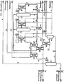
Die Erfindung soll nachstehend an einem Ausführungsbeispiel erläutert werden. In der zugehörigen Zeichnung ist das Funktionsschema einer Anlage zur Regeneration von verunreinigter Waschlösung, in der CO2 und Schwefelverbindungen als Verunreinigungen gebunden sind, gezeigt.The invention will be explained below using an exemplary embodiment. In the accompanying drawing is the functional diagram of a plant for the regeneration of contaminated Washing solution in which CO 2 and sulfur compounds are bound as impurities shown.
Die Anlage ist z.B. Bestandteil einer Biogasaufbereitungsanlage, in der im Biogas enthaltenes CO2 und Schwefelverbindungen mittels einer Aminwäsche entfernt werden. Um eine Wiederverwendung der aminhaltigen Waschlösung zu ermöglichen, ist es erforderlich, aus dieser die Verunreinigungen, CO2 und Schwefelverbindungen, vollständig zu entfernen. Die anfallende verunreinigte Waschlösung (ca. 9 m3/h) mit einer Aminkonzentration von 40 %, einer Temperatur von 38 °C und einer Beladung von 85 g CO2/l und 6 g H2S/l wird über die Leitung 1 zugeführt und mittels der Kreislaufpumpe P1 über drei in Reihe geschaltete Wärmetauscher W1, W2 und W3 geleitet und in diesen stufenweise, auf ca. 65 °C und nachfolgend bis auf ca.125 °C, erwärmt und bis auf einen Druck von 7,5 bar komprimiert. Anschließend gelangt die heiße, verunreinigte Waschlösung in eine erste Flashentspannungsvorrichtung F1 (erste Entspannungsstufe) und wird in dieser auf einen Druck von ca. 4,5 bar entspannt. Während des Entspannungsvorganges werden ca. 60 % der in der Waschlösung chemisch gebundenen Verunreinigungen (Kohlendioxid und Schwefelverbindungen) innerhalb einer Nachreaktionszeit von unter 400 s und einer Reaktionstemperatur von ca. 125 °C freigesetzt, die am Kopf der Flashentspannungsvorrichtung F1 als Brüden über die Leitung 6 abgezogen werden. Unter diesen Bedingungen reduziert sich in der Waschlösung der Anteil an chemisch gebundenem CO2 von 85 g/l auf 40 g/l und an Schwefelverbindungen von 6 g/l auf 4 g/l. Die teilweise gereinigte Waschlösung wird nunmehr mittels der Pumpe P2 über die Leitung 2 einem weiteren Wärmetauscher W4 zugeführt, mittels Thermalöl als Wärmeträger auf eine Temperatur von ca. 140 °C erwärmt, auf einen Druck von 6,5 bar komprimiert, in eine zweite Flashentspannungsvorrichtung F2 (zweite Entspannungsstufe) geleitet und in dieser auf einen Druck von ca. 5,5 bar entspannt. Während der Flashentspannung werden die Anteile an chemisch gebundenem CO2 von 40 g/l auf 22 g/l und an Schwefelverbindungen von 4 g/l auf 2,5 g/l reduziert. Die abgetrennten Verunreinigungen werden am Kopf der Flashentspannungsvorrichtung F2 als Brüden über die Leitung 6 abgezogen. Anschließend erfolgt eine weitere Druckreduzierung von 5,5 auf 4,5 bar. Dadurch wird der Wasseranteil in den Brüden deutlich reduziert und damit insgesamt weniger Energie für die Reinigung der Waschlösung benötigt. Am Boden wird die gereinigte Waschlösung über die Leitung 3 abgeführt und in zwei Teilströme aufgeteilt. Die Abzweigleitung 3b ist als Leitungsschlaufe ausgeführt, die in die Flashentspannungsvorrichtung F2 zurückgeführt ist. In diese Kreislaufleitung 3b sind eine Pumpe P3 und ein Wärmetauscher W7 eingebunden, der mittels Thermalöl als Wärmeträger beheizt wird. Somit wird kontinuierlich über die Leitung 3b ein Teilstrom an Waschlösung (18 m3/h) gepumpt und im Kreislauf gefahren. Über den zwischengeschalteten Wärmetauscher W7 wird die Temperatur der im Kreislauf gefahrenen Waschlösung auf ca. 145 °C konstant gehalten. Unter diesen Bedingungen reduziert sich in der Waschlösung der Anteil von chemisch gebundenem CO2 von 22 g/l auf 8 g/l und an Schwefelverbindungen von 2,5 g/l auf 0,9 g/l. Damit wird insgesamt eine Waschmittelbeladung von 77 g/l für die Entfernung von Kohlendioxid und 5,1 g/l für die Entfernung von Schwefelverbindungen erreicht. Erforderlichenfalls kann noch eine weitere, nicht gezeigte Flashentspannungsstufe nachgeschaltet werden, wodurch die Beladekapazität der Waschlösung weiter geringfügig gesteigert werden kann.The plant is, for example, part of a biogas upgrading plant in which CO 2 and sulfur compounds contained in the biogas are removed by means of amine scrubbing. In order to allow reuse of the amine-containing wash solution, it is necessary to completely remove from this the impurities, CO 2 and sulfur compounds. The resulting contaminated wash solution (about 9 m 3 / h) with an amine concentration of 40%, a temperature of 38 ° C and a loading of 85 g CO 2 / l and 6 g H 2 S / l is fed via line 1 and by means of the circulation pump P1 via three series-connected heat exchangers W1, W2 and W3 and in these gradually, to about 65 ° C and then to about 125 ° C, heated and compressed to a pressure of 7.5 bar , Subsequently, the hot, contaminated washing solution enters a first flash relaxation device F1 (first expansion stage) and is depressurized in this to a pressure of about 4.5 bar. During the relaxation process, about 60% of the chemically bound in the wash solution impurities (carbon dioxide and sulfur compounds) within a post-reaction time of less than 400 s and a reaction temperature of about 125 ° C released at the top of the Flashentspannungsvorrichtung F1 as vapors via the line. 6 subtracted from. Under these conditions, the proportion of chemically bound CO 2 in the scrubbing solution is reduced from 85 g / l to 40 g / l and to sulfur compounds from 6 g / l to 4 g / l. The partially cleaned washing solution is now fed by means of the pump P2 via the line 2 to a further heat exchanger W4, heated by thermal oil as a heat transfer medium to a temperature of about 140 ° C, compressed to a pressure of 6.5 bar, in a second Flashentspannungsvorrichtung F2 (second expansion stage) passed and relaxed in this to a pressure of about 5.5 bar. During flash relaxation, the proportions of chemically bound CO 2 are reduced from 40 g / l to 22 g / l and to sulfur compounds from 4 g / l to 2.5 g / l. The separated impurities are withdrawn as vapor via the line 6 at the head of the Flashentspannungsvorrichtung F2. Subsequently, a further pressure reduction from 5.5 to 4.5 bar. As a result, the water content in the vapors is significantly reduced and thus less energy is needed to clean the washing solution. At the bottom, the purified washing solution is discharged via the line 3 and divided into two partial streams. The
Das Verhältnis zwischen der ausgekreisten Teilstrommenge und der über die Leitung 1 zugeführten Menge an verunreinigter Waschlösung beträgt 0,2 bis 5. Die über die Teilstromleitung 3a abgeführte Menge (9 m3/h) an Waschlösung mit einer Temperatur von ca.145 °C wird durch den Wärmetauscher W2 geleitet und dabei als Wärmeträger zur Erwärmung der verunreinigten Waschlösung genutzt und dadurch bis auf ca. 68 °C abgekühlt. In einem nachgeschalteten Wärmetauscher W5 wird die Waschlösung mittels Kühlwasser weiter abgekühlt (bis auf 22 °C) und druckgeregelt in den Abscheider A1 geleitet. In diesem erfolgt eine weitere Druckreduzierung von 4,5 bar auf Normaldruck. Dadurch wird eine Rücklösung von noch chemisch gebundenem CO2 bewirkt, wodurch ein maximal möglicher Reinheitsgrad der Waschlösung erzielt wird. Das am Kopf des Abscheiders A1 abströmende Gasgemisch (CO2 und Schwefelverbindungen) wird über die Leitung 9 abgeführt.The ratio between the circled partial flow amount and the amount of contaminated washing solution supplied via line 1 is from 0.2 to 5. The amount discharged via the
Das am Kopf der Flashentspannungsvorrichtungen F1 und F2 über die Leitung 6 als Brüden abgezogene Gasgemisch aus Kohlendioxid. Wasser und Schwefelverbindungen wird über den Wärmetauscher W1 geleitet und als Wärmeträger zur Erwärmung der verunreinigten Waschlösung genutzt und dabei auf eine Temperatur von ca. 60 °C abgekühlt, anschließend in einem nachgeschalteten Wärmetauscher W6 mittels Kühlwasser weiter bis auf Normaltemperatur (ca. 25 °C) abgekühlt und in den Abscheider A2 geleitet. In diesem wird kondensiertes Wasser abgeschieden, das in dosierter Menge über die Leitung 7 in den Abscheider A1 geleitet wird und sich mit in diesem befindlicher, vollständig gereinigter Waschlösung vermischt. Der Gasstrom aus Kohlendioxid und Schwefelverbindungen wird über die Leitung 8 abgeführt. Der Arbeitsdruck im Abscheider A2 entspricht in etwa dem Druck in der Flashentspannungsvorrichtung F1 (ca. 4,5 bar).The gas mixture of carbon dioxide taken off at the top of the flash release devices F1 and F2 via the line 6 as vapors. Water and sulfur compounds are passed through the heat exchanger W1 and used as a heat carrier for heating the contaminated wash solution and thereby cooled to a temperature of about 60 ° C, then in a downstream heat exchanger W6 using cooling water on down to normal temperature (about 25 ° C) cooled and passed into the separator A2. In this condensed water is separated, which is passed in metered quantity via the line 7 in the separator A1 and mixed with in this befindlicher, completely purified washing solution. The gas stream of carbon dioxide and sulfur compounds is removed via the line 8. The working pressure in the separator A2 corresponds approximately to the pressure in the Flashentspannungsvorrichtung F1 (about 4.5 bar).
Die im Abscheider A1 anfallende, vollständig gereinigte Waschlösung (9 m3/h), die frei von CO2 und Schwefelverbindungen ist, wird mittels der Pumpe P4 über die Leitung 4 dem Gaswäscher der Biogasaufbereitungsanlage zugeführt. In der Leitung 4 wird der pH-Wert der gereinigten Waschlösung überwacht und erforderlichenfalls die über die Leitung 7 zugeführte Menge an Kondenswasser eingestellt.The resulting in the separator A1, fully purified washing solution (9 m 3 / h), which is free of CO 2 and sulfur compounds is supplied by means of the pump P4 via the line 4 to the gas scrubber biogas upgrading plant. In line 4, the pH of the purified washing solution is monitored and, if necessary, adjusted via the line 7 amount of condensed water.
Aufgrund der hohen Beladungskapazität der aminhaltigen Waschlösung kann der Waschprozess im Vergleich zu der bekannten Verfahrensweise mit einer deutlich höheren spezifischen Leistung durchgeführt werden. Demzufolge werden für den Waschprozess geringere spezifische Waschmittelmengen benötigt. Da sich Kohlenwasserstoffe (im Biogas enthaltenes Methan) bedingt im Waschmittel lösen, werden bei Einsatz geringerer Waschmittelmengen geringere Mengen an Kohlenwasserstoffe gelöst, so dass das gereinigte Biogas einen höheren Methangehalt aufweist.Due to the high loading capacity of the amine-containing washing solution, the washing process can be carried out in comparison to the known procedure with a significantly higher specific power. As a result, lower specific amounts of detergent are needed for the washing process. Since hydrocarbons (biogas contained in biogas) dissolve conditionally in the detergent, lower amounts of hydrocarbons are dissolved when using lower amounts of detergent, so that the purified biogas has a higher methane content.
Die vorgeschlagene Lösung zur Regeneration der verunreinigten Waschlösung zeichnet sich auch durch eine energetisch effektive Betriebsweise aus, da nur die Wärmetauscher W3, W4 und W7 mittels extern zugeführtem Thermalöl als Wärmeträger beheizt werden müssen, wobei der Wärmetauscher W3 in der Regel nur während der Anfahrphase in Betrieb genommen wird. Die Zu- und Abführung des Thermalöls erfolgt über die Leitungen 5. Die Wärmetauscher W1 und W2 werden mittels der im Prozess anfallenden heißen Brüden bzw. der gereinigten Waschlösung beheizt. In den Wärmetauschern W5 und W6 wird zusätzlich durch Wärmerückgewinnung Warmwasser erzeugt, das anderweitig, z. B. als Wärmetauschermedium in der Biogasaufbereitung, genutzt werden kann. Das Kühlwasser wird über die Leitungen 10 zu- und als Warmwasser abgeführt.The proposed solution for the regeneration of the contaminated washing solution is also characterized by an energetically effective mode of operation, since only the heat exchangers W3, W4 and W7 are heated by means of externally supplied thermal oil as the heat carrier must, with the heat exchanger W3 is usually taken only during the start-up phase in operation. The supply and discharge of the thermal oil via the
Die über die Leitungen 8 und 9 abgeführten Gasströme (CO2 und Schwefelverbindungen) werden einer gesonderten Verwendung zugeführt.The discharged via the
Claims (13)
- Method of regenerating an amine-containing scrubbing solution which is obtained during gas purification and in which the CO2 and sulfur compounds are chemically bound, with the contaminated scrubbing solution heated in several stages each time to a higher temperature and the impurities removed from the scrubbing solution in the process and the purified scrubbing solution cooled with the recovery of waste heat, characterized in thata) the contaminated scrubbing solution is heated to a temperature of at least 110°C and compressed to a pressure of at least 4 bar and subsequently expanded in a first expansion stage, with the major proportion of CO2 and sulfur compounds removed from the scrubbing solution as a gas stream,b) the scrubbing solution removed is heated to a temperature at least 130°C and compressed to a pressure of at least 4 bar and expanded in a second expansion stage to a pressure that is at least 0.5 bar higher than the expansion pressure of the first expansion stage, with the major proportion of the CO2 and sulfur compounds still present removed from the scrubbing solution as a gas streamc) the scrubbing solution removed in the second expansion stage is cooled to a temperature below 70°C and expanded to normal pressure in a third expansion stage with the residual amounts of soluble CO2 still present removed and this partial stream cooled to normal temperature as a completely purified scrubbing solution, andd) the scrubbing solution removed after the first expansion stage and/or second expansion stage is subdivided into two partial streams, with one partial stream in the circuit returned to the respective expansion stage and its temperature and pressure adjusted to the conditions of the associated expansion stage, with residual amounts of sulfur compounds still present removed from this partial stream during the expansion and with the other partial stream further processed in accordance with either process step b) or c).
- Method according to claim 1, characterized in that the gas mixture composed of carbon dioxide, water and sulfur compounds removed in the expansion stages as vapors in accordance with the process steps a) and b) is used as a heat carrier for heating the contaminated scrubbing solution and is cooled to normal temperature.
- Method according to one of the claims 1 or 2, characterized in that condensed water is removed from the gas mixture (vapors) which have been cooled to normal temperature, and the condensed water is mixed at a dosed amount with the completely purified scrubbing solution.
- Method according to one of the claims 1 to 3, characterized in that the contaminated scrubbing solution is compressed before expansion to a pressure of 6 to 12 bar and is expanded during the expansion to a pressure of 1 to 8 bar.
- Method according to one of the claims 1 to 4, characterized in that a flash expansion is carried out in the expansion stages in accordance with the process steps a) and b).
- Method according to one of the claims 1 to 5, characterized in that the purified scrubbing solution obtained in the second expansion stage is used as a heat carrier for heating the contaminated scrubbing solution.
- Method according to one of the claims 1 to 6, characterized in that the gas stream removed in the first and second expansion stage at least is desulfurized in a downstream desulfurization plant.
- Method according to one of the claims 1 to 7, characterized in that the scrubbing solution undergoes ultrasonic treatment during the first expansion stage.
- Method according to one of the claims 1 to 8, characterized in that the pH of the purified scrubbing solution is measured and serves as a control variable for adjusting the temperature of the contaminated scrubbing solution in the expansion stages.
- Method according to one of the claims 1 to 9, characterized in that in an expansion stage the ratio of the amount fed of the partial stream led back in the respective expansion stage to the amount fed in of contaminated scrubbing solution is 0.2 to 5.
- System for carrying out the method in accordance with at least one of the previous claims characterized in that a circulation line (1, 2, 3, 3a, 4) for conveying the scrubbing solution is planned, with a first pump (P1), at least one heat exchanger (W1, W2, W3), at least two expansion devices (F1, F2) connected in series and a first separator (A1) integrated into the said circulation line in the direction of flow, with a second pump (P2) and a downstream heat exchanger (W4) arranged between both expansion devices (F1, F2), with a loop line (3b) integrated into the circulation line (3) downstream of at least one of the expansion devices (F2) and connected to the expansion device (F2) for removing a partial amount of purified scrubbing solution from the circuit and with a third pump (P3) and a heat exchanger (W7) integrated into the loop line (3a).
- System according to claim 11, characterized in that a line (6) for removing the vapors is arranged at the head of the expansion devices (F1, F2), said line being connected to a second separator (A2) for removing the condensed water, with at least one heat exchanger (W1, W6) for cooling the vapors integrated into this line, and the second separator connected to the first separator (A1) via a line (7) for conveying condensed water.
- System according to claims 11 or 12, characterized in that three heat exchangers (W1, W2, W3) connected in series for the gradual heating of the contaminated scrubbing solution to the required operating temperature are arranged upstream of the first expansion device (F1), with the first heat exchanger (W1) integrated into the line (6) conveying the vapors and the second heat exchanger (W2) integrated into the line (3a) conveying the purified, hot scrubbing solution, and the third heat exchanger (W3) capable of being heated by means of an external heat carrier and capable of being switched on intermittently.
Priority Applications (2)
| Application Number | Priority Date | Filing Date | Title |
|---|---|---|---|
| SI200830654T SI2197566T1 (en) | 2007-10-09 | 2008-08-12 | Method and system for regenerating an amine-containing wash solution obtained during gas purification |
| PL08785494T PL2197566T3 (en) | 2007-10-09 | 2008-08-12 | Method and system for regenerating an amine-containing wash solution obtained during gas purification |
Applications Claiming Priority (2)
| Application Number | Priority Date | Filing Date | Title |
|---|---|---|---|
| DE102007048565A DE102007048565B3 (en) | 2007-10-09 | 2007-10-09 | Process and plant for the regeneration of an amine-containing washing solution resulting from the purification of gases |
| PCT/EP2008/006615 WO2009092403A1 (en) | 2007-10-09 | 2008-08-12 | Method and system for regenerating an amine-containing wash solution obtained during gas purification |
Publications (2)
| Publication Number | Publication Date |
|---|---|
| EP2197566A1 EP2197566A1 (en) | 2010-06-23 |
| EP2197566B1 true EP2197566B1 (en) | 2012-05-02 |
Family
ID=39929675
Family Applications (1)
| Application Number | Title | Priority Date | Filing Date |
|---|---|---|---|
| EP08785494A Active EP2197566B1 (en) | 2007-10-09 | 2008-08-12 | Method and system for regenerating an amine-containing wash solution obtained during gas purification |
Country Status (18)
| Country | Link |
|---|---|
| US (1) | US8460431B2 (en) |
| EP (1) | EP2197566B1 (en) |
| JP (1) | JP5655245B2 (en) |
| CN (1) | CN101820969B (en) |
| AT (1) | ATE555842T1 (en) |
| AU (1) | AU2008348856A1 (en) |
| BR (1) | BRPI0818503A8 (en) |
| CA (1) | CA2701667C (en) |
| DE (1) | DE102007048565B3 (en) |
| DK (1) | DK2197566T3 (en) |
| ES (1) | ES2385627T3 (en) |
| HR (1) | HRP20120580T1 (en) |
| PL (1) | PL2197566T3 (en) |
| PT (1) | PT2197566E (en) |
| RU (1) | RU2480401C2 (en) |
| SI (1) | SI2197566T1 (en) |
| UA (1) | UA100391C2 (en) |
| WO (1) | WO2009092403A1 (en) |
Families Citing this family (11)
| Publication number | Priority date | Publication date | Assignee | Title |
|---|---|---|---|---|
| ATE514667T1 (en) * | 2007-01-30 | 2011-07-15 | Mt Biomethan Gmbh | METHOD AND PLANT FOR THE TREATMENT OF RAW GASES CONTAINING METHANE AND CARBON DIOXIDE, IN PARTICULAR BIOGAS, TO PRODUCE METHANE |
| DE102008025971A1 (en) * | 2008-05-30 | 2009-12-03 | Dge Dr.-Ing. Günther Engineering Gmbh | Process and plant for the purification of biogas for the production of methane |
| DE102009009753B4 (en) | 2009-02-20 | 2014-01-30 | Mt-Biomethan Gmbh | Process for the chemisorptive purification of biogas or sewage gas |
| FR2954178B1 (en) * | 2009-12-21 | 2014-02-21 | Air Liquide | PROCESS FOR PURIFYING A GAS CONTAINING CARBON DIOXIDE |
| CN102059037A (en) * | 2010-11-22 | 2011-05-18 | 重庆欣雨压力容器制造有限责任公司 | Process for purifying carbon dioxide from tail gas of natural gas |
| DE102011016604A1 (en) * | 2011-04-09 | 2012-10-11 | Dge Dr.-Ing. Günther Engineering Gmbh | Method and device for producing biogas from fermentation substrate |
| EP2609988A1 (en) | 2011-12-29 | 2013-07-03 | Dreyer & Bosse Kraftwerke GmbH | Low temperature method for desorption of charged washing liquids containing amines from gas washing processes and device |
| DE102012110640B4 (en) | 2012-10-25 | 2018-07-26 | Dge Dr.-Ing. Günther Engineering Gmbh | Method for removing carbon dioxide from biogas by means of an amine-containing washing solution and regeneration of the resulting loaded washing solution |
| DE102013019357A1 (en) | 2013-11-19 | 2015-05-21 | Thyssenkrupp Industrial Solutions Ag | Process and apparatus for purifying process gases from the oxidative dehydrogenation of hydrocarbons |
| DE102014110190B4 (en) * | 2014-07-19 | 2021-11-11 | Dge Dr.-Ing. Günther Engineering Gmbh | Process for the separation of carbon dioxide from biogas by means of an amine-containing scrubbing solution and regeneration of the loaded scrubbing solution as well as systems for carrying out the process |
| CN105561787A (en) * | 2014-10-14 | 2016-05-11 | 中国石油化工股份有限公司 | Regeneration method of SO2-rich organic amine solution |
Family Cites Families (24)
| Publication number | Priority date | Publication date | Assignee | Title |
|---|---|---|---|---|
| DE3232802A1 (en) * | 1982-09-03 | 1984-03-08 | Alfred Prof. Dr.-Ing. 7830 Emmendingen Walz | METHOD AND DEVICE FOR PRODUCING ULTRAVIOLETTER RADIATION |
| DE3343916A1 (en) * | 1983-12-05 | 1985-06-13 | Linde Ag, 6200 Wiesbaden | METHOD AND DEVICE FOR REGENERATING A SOLVENT |
| DE3401773A1 (en) * | 1984-01-19 | 1985-08-01 | Linde Ag, 6200 Wiesbaden | METHOD FOR SEPARATING AND SIMULTANEOUSLY DETERMINING ACID IMPURITIES FROM GAS MIXTURES |
| IT1190357B (en) * | 1985-05-24 | 1988-02-16 | Snam Progetti | CRYOGENIC PROCEDURE FOR REMOVAL OF ACID GASES FROM GAS MIXTURES BY SOLVENT |
| US4702898A (en) * | 1986-10-17 | 1987-10-27 | Union Carbide Corporation | Process for the removal of acid gases from gas mixtures |
| NO874821L (en) * | 1986-12-02 | 1988-06-03 | Norton Co | PROCEDURE FOR AA REMOVING CARBON DIOXIDE FROM A GAS. |
| DE3709363C1 (en) * | 1987-03-21 | 1988-08-18 | Metallgesellschaft Ag | Process for treating two loaded wash solution streams |
| JP2882950B2 (en) * | 1992-09-16 | 1999-04-19 | 関西電力株式会社 | Method for removing carbon dioxide in flue gas |
| FR2777802B1 (en) * | 1998-04-22 | 2000-06-23 | Elf Exploration Prod | REGENERATIVE PROCESS FOR DEACIDIFYING A CO2-CONTAINING GAS AS WELL AS LIQUID HYDROCARBONS USING AN ACTIVATED METHYLDIETHANOLAMINE ABSORBENT LIQUID |
| US6337059B1 (en) * | 1999-05-03 | 2002-01-08 | Union Carbide Chemicals & Plastics Technology Corporation | Absorbent compositions for the removal of acid gases from gas streams |
| CN1168525C (en) * | 2001-12-10 | 2004-09-29 | 大连理工大学 | Energy saving raw material gas purifying methanol washing method |
| US7192468B2 (en) * | 2002-04-15 | 2007-03-20 | Fluor Technologies Corporation | Configurations and method for improved gas removal |
| EA009089B1 (en) * | 2002-12-12 | 2007-10-26 | Флуор Корпорейшн | Configurations and methods of acid gas removal |
| DE20300663U1 (en) * | 2003-01-16 | 2004-08-12 | Farmatic Biotech Energy Ag | Assembly to remove carbon dioxide and hydrogen sulfide from methane biogas by compression and release into an absorption column |
| CA2518458C (en) * | 2003-03-10 | 2013-01-29 | Gary Rochelle | Regeneration of an aqueous solution from an acid gas absorption process by multistage flashing and stripping |
| DE10313438A1 (en) * | 2003-03-26 | 2004-11-04 | Uhde Gmbh | Process for the selective removal of hydrogen sulfide and CO2 from raw gas |
| DE10324694A1 (en) * | 2003-05-28 | 2004-12-23 | Uhde Gmbh | Process for the removal of acid gases from pressurized natural gas contaminated with acid gas compounds and recovery of the removed acid gases at an elevated pressure level |
| DE10325358A1 (en) * | 2003-06-05 | 2004-12-23 | Basf Ag | Deacidifying fluid stream containing acid gas impurities, e.g. from fuel combustion, involves performing at least one absorption stage in inert scrubber column with plastic or rubber interior surface |
| EP1633458A2 (en) * | 2003-06-05 | 2006-03-15 | Basf Aktiengesellschaft | Method for the deacidification of a fluid stream by means of an inert scrubbing column and corresponding device |
| JP2007533431A (en) * | 2003-11-10 | 2007-11-22 | ビーエーエスエフ アクチェンゲゼルシャフト | Method for obtaining an acid gas stream under high pressure by removing acid gas from a fluid stream |
| DE102004011427A1 (en) * | 2004-03-09 | 2005-09-29 | Basf Ag | Absorbent with improved oxidation resistance and process for deacidifying fluid streams |
| DE102005051952B3 (en) * | 2005-10-29 | 2006-12-21 | Dge Dr.-Ing. Günther Engineering Gmbh | Preparing methane and liquid carbon dioxide from biogas, comprises contacting prepurified biogas; absorbing carbon dioxide by wash solution; compressing obtained detergent; supplying to desorption column; and condensing carbon dioxide |
| US7699914B1 (en) * | 2005-12-09 | 2010-04-20 | Morrow Luke N | Triple-effect absorption system for recovering methane gas |
| FR2911516B1 (en) * | 2007-01-19 | 2009-11-13 | Total Sa | PROCESS FOR PURIFYING A GASEOUS MIXTURE CONTAINING ACIDIC GASES |
-
2007
- 2007-10-09 DE DE102007048565A patent/DE102007048565B3/en not_active Expired - Fee Related
-
2008
- 2008-08-12 BR BRPI0818503A patent/BRPI0818503A8/en not_active IP Right Cessation
- 2008-08-12 PL PL08785494T patent/PL2197566T3/en unknown
- 2008-08-12 UA UAA201005583A patent/UA100391C2/en unknown
- 2008-08-12 US US12/682,308 patent/US8460431B2/en active Active
- 2008-08-12 CA CA2701667A patent/CA2701667C/en not_active Expired - Fee Related
- 2008-08-12 AU AU2008348856A patent/AU2008348856A1/en not_active Abandoned
- 2008-08-12 EP EP08785494A patent/EP2197566B1/en active Active
- 2008-08-12 DK DK08785494.9T patent/DK2197566T3/en active
- 2008-08-12 ES ES08785494T patent/ES2385627T3/en active Active
- 2008-08-12 AT AT08785494T patent/ATE555842T1/en active
- 2008-08-12 CN CN2008801108016A patent/CN101820969B/en not_active Expired - Fee Related
- 2008-08-12 SI SI200830654T patent/SI2197566T1/en unknown
- 2008-08-12 PT PT08785494T patent/PT2197566E/en unknown
- 2008-08-12 RU RU2010118215/05A patent/RU2480401C2/en not_active IP Right Cessation
- 2008-08-12 WO PCT/EP2008/006615 patent/WO2009092403A1/en active Application Filing
- 2008-08-12 JP JP2010528281A patent/JP5655245B2/en not_active Expired - Fee Related
-
2012
- 2012-07-12 HR HRP20120580AT patent/HRP20120580T1/en unknown
Also Published As
| Publication number | Publication date |
|---|---|
| HRP20120580T1 (en) | 2012-08-31 |
| JP5655245B2 (en) | 2015-01-21 |
| CN101820969A (en) | 2010-09-01 |
| ATE555842T1 (en) | 2012-05-15 |
| DK2197566T3 (en) | 2012-08-20 |
| CN101820969B (en) | 2013-08-28 |
| SI2197566T1 (en) | 2012-08-31 |
| JP2010540243A (en) | 2010-12-24 |
| AU2008348856A1 (en) | 2009-07-30 |
| BRPI0818503A8 (en) | 2016-05-31 |
| PL2197566T3 (en) | 2012-09-28 |
| CA2701667C (en) | 2016-10-18 |
| UA100391C2 (en) | 2012-12-25 |
| CA2701667A1 (en) | 2009-07-30 |
| US8460431B2 (en) | 2013-06-11 |
| WO2009092403A1 (en) | 2009-07-30 |
| ES2385627T3 (en) | 2012-07-27 |
| EP2197566A1 (en) | 2010-06-23 |
| US20100282074A1 (en) | 2010-11-11 |
| RU2480401C2 (en) | 2013-04-27 |
| PT2197566E (en) | 2012-07-24 |
| BRPI0818503A2 (en) | 2015-04-22 |
| DE102007048565B3 (en) | 2009-01-22 |
| RU2010118215A (en) | 2011-11-27 |
Similar Documents
| Publication | Publication Date | Title |
|---|---|---|
| EP2197566B1 (en) | Method and system for regenerating an amine-containing wash solution obtained during gas purification | |
| EP1953130B1 (en) | Method and installation for raw gases containing processing methane and carbon dioxide, in particular biogas, for extracting methane | |
| EP2382028B1 (en) | Method for separating carbon dioxide from an exhaust gas of a fossil fired power plant | |
| DE102008060310B4 (en) | Process and plant for the purification of raw or biogas for the production of methane | |
| DE102014110190B4 (en) | Process for the separation of carbon dioxide from biogas by means of an amine-containing scrubbing solution and regeneration of the loaded scrubbing solution as well as systems for carrying out the process | |
| DE1951277A1 (en) | Process for the elimination and recovery of contamination in gas mixtures | |
| DE3112792C2 (en) | Process for the regeneration of an absorption solution which is loaded with one or more gaseous compounds which can be released by heating and / or carried away by stripping, and plant for carrying out the process | |
| DE2750621C2 (en) | Process for removing gaseous contaminants from gas mixtures | |
| DE2407405A1 (en) | METHOD FOR THE REGENERATION OF ABSORPTION SOLUTIONS USED FOR THE REMOVAL OF GASEOUS POLLUTIONS FROM GAS MIXTURES BY WIPING WITH WATER VAPOR | |
| DE102007005494A1 (en) | Producing liquid methane from a gas containing methane and carbon dioxide comprises scrubbing the gas to remove carbon dioxide and using the liquefied carbon dioxide to liquefy the methane | |
| EP1289625B1 (en) | Method for neutralising a stream of hydrocarbon fluid | |
| DE102017222030A1 (en) | Process for the provision of CO2 for the synthesis of urea from smoke and synthesis gas | |
| WO2013013749A1 (en) | Heat recovery in absorption and desorption processes | |
| DE3248585A1 (en) | CIRCUIT METHOD FOR THE REMOVAL OF ACID GAS FROM A CHARGING GAS FLOW CONTAINING A HOT GAS MIXTURE CONTAINING WATER VAPOR | |
| DE10011335A1 (en) | Production of nitric acid of specified concentration, useful in the production of adipic acid, caprolactam, toluene diisocyanate etc., by one- or 2-pressure combustion of ammonia and absorption uses dried air supply | |
| DE2916993C2 (en) | ||
| DE102009056660B4 (en) | Process and installation for the chemisorptive separation of carbon dioxide from biological or sewage gas by means of an amine-containing washing solution and regeneration of the loaded washing solution | |
| DE102013010103B4 (en) | Process and device for separating metal carbonyls from gas mixtures | |
| DE102007004628A1 (en) | Method for treating application existing for predominant part made of nitrogen, carbon monoxide and hydrogen, involves obtaining dihydrogen or carbon monoxide product and another product consisting of air components | |
| DE2828001A1 (en) | METHOD FOR PRODUCTION OF HYDROGEN | |
| DE1568845A1 (en) | Process for the production of urea from ammonia and carbon dioxide | |
| EP2822673A1 (en) | Method and installation for separating carbon dioxide from biogas | |
| EP3601498B1 (en) | Process and apparatus for desulfuration of a gas stream containing hydrogen sulfide | |
| EP1519781B1 (en) | System unit for desorbing carbon dioxide from methanol | |
| EP3132840A1 (en) | Method and device for the separation of gaseous pollutants from a gas flow |
Legal Events
| Date | Code | Title | Description |
|---|---|---|---|
| PUAI | Public reference made under article 153(3) epc to a published international application that has entered the european phase |
Free format text: ORIGINAL CODE: 0009012 |
|
| 17P | Request for examination filed |
Effective date: 20100503 |
|
| AK | Designated contracting states |
Kind code of ref document: A1 Designated state(s): AT BE BG CH CY CZ DE DK EE ES FI FR GB GR HR HU IE IS IT LI LT LU LV MC MT NL NO PL PT RO SE SI SK TR |
|
| AX | Request for extension of the european patent |
Extension state: AL BA MK RS |
|
| DAX | Request for extension of the european patent (deleted) | ||
| RAP1 | Party data changed (applicant data changed or rights of an application transferred) |
Owner name: MT-BIOMETHAN GMBH |
|
| GRAP | Despatch of communication of intention to grant a patent |
Free format text: ORIGINAL CODE: EPIDOSNIGR1 |
|
| GRAS | Grant fee paid |
Free format text: ORIGINAL CODE: EPIDOSNIGR3 |
|
| GRAA | (expected) grant |
Free format text: ORIGINAL CODE: 0009210 |
|
| AK | Designated contracting states |
Kind code of ref document: B1 Designated state(s): AT BE BG CH CY CZ DE DK EE ES FI FR GB GR HR HU IE IS IT LI LT LU LV MC MT NL NO PL PT RO SE SI SK TR |
|
| REG | Reference to a national code |
Ref country code: GB Ref legal event code: FG4D Free format text: NOT ENGLISH |
|
| REG | Reference to a national code |
Ref country code: AT Ref legal event code: REF Ref document number: 555842 Country of ref document: AT Kind code of ref document: T Effective date: 20120515 Ref country code: CH Ref legal event code: EP |
|
| REG | Reference to a national code |
Ref country code: IE Ref legal event code: FG4D Free format text: LANGUAGE OF EP DOCUMENT: GERMAN |
|
| REG | Reference to a national code |
Ref country code: RO Ref legal event code: EPE |
|
| REG | Reference to a national code |
Ref country code: DE Ref legal event code: R096 Ref document number: 502008007139 Country of ref document: DE Effective date: 20120628 |
|
| REG | Reference to a national code |
Ref country code: HR Ref legal event code: TUEP Ref document number: P20120580 Country of ref document: HR |
|
| REG | Reference to a national code |
Ref country code: PT Ref legal event code: SC4A Free format text: AVAILABILITY OF NATIONAL TRANSLATION Effective date: 20120716 |
|
| REG | Reference to a national code |
Ref country code: ES Ref legal event code: FG2A Ref document number: 2385627 Country of ref document: ES Kind code of ref document: T3 Effective date: 20120727 |
|
| REG | Reference to a national code |
Ref country code: NL Ref legal event code: T3 |
|
| REG | Reference to a national code |
Ref country code: DK Ref legal event code: T3 |
|
| REG | Reference to a national code |
Ref country code: SE Ref legal event code: TRGR |
|
| REG | Reference to a national code |
Ref country code: HR Ref legal event code: T1PR Ref document number: P20120580 Country of ref document: HR |
|
| REG | Reference to a national code |
Ref country code: NO Ref legal event code: T2 Effective date: 20120502 |
|
| REG | Reference to a national code |
Ref country code: PL Ref legal event code: T3 |
|
| REG | Reference to a national code |
Ref country code: EE Ref legal event code: FG4A Ref document number: E006899 Country of ref document: EE Effective date: 20120730 |
|
| REG | Reference to a national code |
Ref country code: GR Ref legal event code: EP Ref document number: 20120401645 Country of ref document: GR Effective date: 20120903 |
|
| PG25 | Lapsed in a contracting state [announced via postgrant information from national office to epo] |
Ref country code: CY Free format text: LAPSE BECAUSE OF FAILURE TO SUBMIT A TRANSLATION OF THE DESCRIPTION OR TO PAY THE FEE WITHIN THE PRESCRIBED TIME-LIMIT Effective date: 20120502 Ref country code: IS Free format text: LAPSE BECAUSE OF FAILURE TO SUBMIT A TRANSLATION OF THE DESCRIPTION OR TO PAY THE FEE WITHIN THE PRESCRIBED TIME-LIMIT Effective date: 20120902 |
|
| REG | Reference to a national code |
Ref country code: SK Ref legal event code: T3 Ref document number: E 12403 Country of ref document: SK |
|
| PLBE | No opposition filed within time limit |
Free format text: ORIGINAL CODE: 0009261 |
|
| STAA | Information on the status of an ep patent application or granted ep patent |
Free format text: STATUS: NO OPPOSITION FILED WITHIN TIME LIMIT |
|
| PG25 | Lapsed in a contracting state [announced via postgrant information from national office to epo] |
Ref country code: MC Free format text: LAPSE BECAUSE OF NON-PAYMENT OF DUE FEES Effective date: 20120831 |
|
| 26N | No opposition filed |
Effective date: 20130205 |
|
| REG | Reference to a national code |
Ref country code: HU Ref legal event code: AG4A Ref document number: E015252 Country of ref document: HU |
|
| REG | Reference to a national code |
Ref country code: DE Ref legal event code: R097 Ref document number: 502008007139 Country of ref document: DE Effective date: 20130205 |
|
| PG25 | Lapsed in a contracting state [announced via postgrant information from national office to epo] |
Ref country code: MT Free format text: LAPSE BECAUSE OF FAILURE TO SUBMIT A TRANSLATION OF THE DESCRIPTION OR TO PAY THE FEE WITHIN THE PRESCRIBED TIME-LIMIT Effective date: 20120502 |
|
| PGFP | Annual fee paid to national office [announced via postgrant information from national office to epo] |
Ref country code: TR Payment date: 20130805 Year of fee payment: 6 |
|
| REG | Reference to a national code |
Ref country code: HR Ref legal event code: ODRP Ref document number: P20120580 Country of ref document: HR Payment date: 20140731 Year of fee payment: 7 |
|
| PGFP | Annual fee paid to national office [announced via postgrant information from national office to epo] |
Ref country code: LU Payment date: 20140821 Year of fee payment: 7 |
|
| PGFP | Annual fee paid to national office [announced via postgrant information from national office to epo] |
Ref country code: IE Payment date: 20140820 Year of fee payment: 7 Ref country code: DK Payment date: 20140825 Year of fee payment: 7 Ref country code: GR Payment date: 20140827 Year of fee payment: 7 Ref country code: NO Payment date: 20140821 Year of fee payment: 7 Ref country code: RO Payment date: 20140805 Year of fee payment: 7 Ref country code: BG Payment date: 20140825 Year of fee payment: 7 Ref country code: LT Payment date: 20140731 Year of fee payment: 7 Ref country code: FI Payment date: 20140820 Year of fee payment: 7 Ref country code: CZ Payment date: 20140730 Year of fee payment: 7 Ref country code: EE Payment date: 20140822 Year of fee payment: 7 |
|
| PGFP | Annual fee paid to national office [announced via postgrant information from national office to epo] |
Ref country code: PL Payment date: 20140801 Year of fee payment: 7 Ref country code: SK Payment date: 20140805 Year of fee payment: 7 Ref country code: AT Payment date: 20140820 Year of fee payment: 7 Ref country code: LV Payment date: 20140822 Year of fee payment: 7 Ref country code: HR Payment date: 20140731 Year of fee payment: 7 Ref country code: HU Payment date: 20140730 Year of fee payment: 7 Ref country code: SI Payment date: 20140717 Year of fee payment: 7 |
|
| PGFP | Annual fee paid to national office [announced via postgrant information from national office to epo] |
Ref country code: PT Payment date: 20140213 Year of fee payment: 7 |
|
| REG | Reference to a national code |
Ref country code: FR Ref legal event code: PLFP Year of fee payment: 8 |
|
| REG | Reference to a national code |
Ref country code: DE Ref legal event code: R082 Country of ref document: DE Ref document number: 502008007139 Representative=s name: WEIDNER STERN JESCHKE PATENTANWAELTE PARTNERSC, DE Ref country code: DE Ref legal event code: R082 Ref document number: 502008007139 Country of ref document: DE Representative=s name: LEDERER & KELLER PATENTANWAELTE PARTNERSCHAFT , DE |
|
| REG | Reference to a national code |
Ref country code: PT Ref legal event code: MM4A Free format text: LAPSE DUE TO NON-PAYMENT OF FEES Effective date: 20160212 |
|
| REG | Reference to a national code |
Ref country code: HR Ref legal event code: PBON Ref document number: P20120580 Country of ref document: HR Effective date: 20150812 |
|
| REG | Reference to a national code |
Ref country code: LT Ref legal event code: MM4D Effective date: 20150812 |
|
| REG | Reference to a national code |
Ref country code: DK Ref legal event code: EBP Effective date: 20150831 |
|
| REG | Reference to a national code |
Ref country code: NO Ref legal event code: MMEP |
|
| PG25 | Lapsed in a contracting state [announced via postgrant information from national office to epo] |
Ref country code: LU Free format text: LAPSE BECAUSE OF NON-PAYMENT OF DUE FEES Effective date: 20150812 |
|
| REG | Reference to a national code |
Ref country code: AT Ref legal event code: MM01 Ref document number: 555842 Country of ref document: AT Kind code of ref document: T Effective date: 20150812 Ref country code: EE Ref legal event code: MM4A Ref document number: E006899 Country of ref document: EE Effective date: 20150831 |
|
| REG | Reference to a national code |
Ref country code: DE Ref legal event code: R082 Ref document number: 502008007139 Country of ref document: DE Representative=s name: LEDERER & KELLER PATENTANWAELTE PARTNERSCHAFT , DE Ref country code: DE Ref legal event code: R082 Ref document number: 502008007139 Country of ref document: DE |
|
| PG25 | Lapsed in a contracting state [announced via postgrant information from national office to epo] |
Ref country code: BG Free format text: LAPSE BECAUSE OF NON-PAYMENT OF DUE FEES Effective date: 20160331 Ref country code: LT Free format text: LAPSE BECAUSE OF NON-PAYMENT OF DUE FEES Effective date: 20150812 Ref country code: CZ Free format text: LAPSE BECAUSE OF NON-PAYMENT OF DUE FEES Effective date: 20150812 Ref country code: HR Free format text: LAPSE BECAUSE OF NON-PAYMENT OF DUE FEES Effective date: 20150813 Ref country code: SK Free format text: LAPSE BECAUSE OF NON-PAYMENT OF DUE FEES Effective date: 20150812 Ref country code: EE Free format text: LAPSE BECAUSE OF NON-PAYMENT OF DUE FEES Effective date: 20150831 Ref country code: NO Free format text: LAPSE BECAUSE OF NON-PAYMENT OF DUE FEES Effective date: 20150831 |
|
| REG | Reference to a national code |
Ref country code: SK Ref legal event code: MM4A Ref document number: E 12403 Country of ref document: SK Effective date: 20150812 |
|
| REG | Reference to a national code |
Ref country code: DE Ref legal event code: R082 Ref document number: 502008007139 Country of ref document: DE Representative=s name: LEDERER & KELLER PATENTANWAELTE PARTNERSCHAFT , DE Ref country code: DE Ref legal event code: R081 Ref document number: 502008007139 Country of ref document: DE Owner name: HZI DEUTSCHLAND GMBH, DE Free format text: FORMER OWNER: MT-BIOMETHAN GMBH, 27404 ZEVEN, DE Ref country code: DE Ref legal event code: R081 Ref document number: 502008007139 Country of ref document: DE Owner name: HITACHI ZOSEN INOVA BIOMETHAN GMBH, DE Free format text: FORMER OWNER: MT-BIOMETHAN GMBH, 27404 ZEVEN, DE |
|
| REG | Reference to a national code |
Ref country code: ES Ref legal event code: PC2A Owner name: HITACHI ZOSEN INOVA BIOMETHAN GMBH Effective date: 20160518 |
|
| REG | Reference to a national code |
Ref country code: DE Ref legal event code: R082 Ref document number: 502008007139 Country of ref document: DE Representative=s name: LEDERER & KELLER PATENTANWAELTE PARTNERSCHAFT , DE Ref country code: DE Ref legal event code: R081 Ref document number: 502008007139 Country of ref document: DE Owner name: HITACHI ZOSEN INOVA BIOMETHAN GMBH, DE Free format text: FORMER OWNER: HZI DEUTSCHLAND GMBH, 51069 KOELN, DE |
|
| PG25 | Lapsed in a contracting state [announced via postgrant information from national office to epo] |
Ref country code: FI Free format text: LAPSE BECAUSE OF NON-PAYMENT OF DUE FEES Effective date: 20150812 Ref country code: AT Free format text: LAPSE BECAUSE OF NON-PAYMENT OF DUE FEES Effective date: 20150812 Ref country code: SI Free format text: LAPSE BECAUSE OF NON-PAYMENT OF DUE FEES Effective date: 20150813 Ref country code: PT Free format text: LAPSE BECAUSE OF NON-PAYMENT OF DUE FEES Effective date: 20160212 Ref country code: GR Free format text: LAPSE BECAUSE OF NON-PAYMENT OF DUE FEES Effective date: 20160303 Ref country code: LV Free format text: LAPSE BECAUSE OF NON-PAYMENT OF DUE FEES Effective date: 20150812 Ref country code: HU Free format text: LAPSE BECAUSE OF NON-PAYMENT OF DUE FEES Effective date: 20150813 Ref country code: RO Free format text: LAPSE BECAUSE OF NON-PAYMENT OF DUE FEES Effective date: 20150812 |
|
| REG | Reference to a national code |
Ref country code: SI Ref legal event code: KO00 Effective date: 20160406 |
|
| REG | Reference to a national code |
Ref country code: IE Ref legal event code: MM4A |
|
| REG | Reference to a national code |
Ref country code: GR Ref legal event code: ML Ref document number: 20120401645 Country of ref document: GR Effective date: 20160303 |
|
| PG25 | Lapsed in a contracting state [announced via postgrant information from national office to epo] |
Ref country code: IE Free format text: LAPSE BECAUSE OF NON-PAYMENT OF DUE FEES Effective date: 20150812 |
|
| REG | Reference to a national code |
Ref country code: FR Ref legal event code: TP Owner name: HITACHI ZOSEN INOVA BIOMETHAN GMBH, DE Effective date: 20160708 |
|
| REG | Reference to a national code |
Ref country code: FR Ref legal event code: PLFP Year of fee payment: 9 |
|
| PG25 | Lapsed in a contracting state [announced via postgrant information from national office to epo] |
Ref country code: DK Free format text: LAPSE BECAUSE OF NON-PAYMENT OF DUE FEES Effective date: 20150831 |
|
| REG | Reference to a national code |
Ref country code: CH Ref legal event code: NV Representative=s name: PATENTANWAELTE SCHAAD, BALASS, MENZL AND PARTN, CH Ref country code: CH Ref legal event code: PUE Owner name: HITACHI ZOSEN INOVA BIOMETHAN GMBH, DE Free format text: FORMER OWNER: HZI DEUTSCHLAND GMBH, DE Ref country code: CH Ref legal event code: PUE Owner name: HZI DEUTSCHLAND GMBH, DE Free format text: FORMER OWNER: MT-BIOMETHAN GMBH, DE |
|
| PGFP | Annual fee paid to national office [announced via postgrant information from national office to epo] |
Ref country code: NL Payment date: 20160819 Year of fee payment: 9 |
|
| REG | Reference to a national code |
Ref country code: NL Ref legal event code: PD Owner name: HITACHI ZOSEN INOVA BIOMETHAN GMBH; DE Free format text: DETAILS ASSIGNMENT: VERANDERING VAN EIGENAAR(S), OVERDRACHT; FORMER OWNER NAME: MT-BIOMETHAN GMBH Effective date: 20160816 |
|
| PG25 | Lapsed in a contracting state [announced via postgrant information from national office to epo] |
Ref country code: PL Free format text: LAPSE BECAUSE OF NON-PAYMENT OF DUE FEES Effective date: 20150812 |
|
| PGFP | Annual fee paid to national office [announced via postgrant information from national office to epo] |
Ref country code: IT Payment date: 20160825 Year of fee payment: 9 Ref country code: CH Payment date: 20160720 Year of fee payment: 9 |
|
| PGFP | Annual fee paid to national office [announced via postgrant information from national office to epo] |
Ref country code: FR Payment date: 20160822 Year of fee payment: 9 |
|
| REG | Reference to a national code |
Ref country code: GB Ref legal event code: 732E Free format text: REGISTERED BETWEEN 20161117 AND 20161123 |
|
| PGFP | Annual fee paid to national office [announced via postgrant information from national office to epo] |
Ref country code: BE Payment date: 20160819 Year of fee payment: 9 |
|
| PG25 | Lapsed in a contracting state [announced via postgrant information from national office to epo] |
Ref country code: TR Free format text: LAPSE BECAUSE OF NON-PAYMENT OF DUE FEES Effective date: 20150812 |
|
| PGFP | Annual fee paid to national office [announced via postgrant information from national office to epo] |
Ref country code: GB Payment date: 20170719 Year of fee payment: 10 |
|
| REG | Reference to a national code |
Ref country code: CH Ref legal event code: PL |
|
| REG | Reference to a national code |
Ref country code: NL Ref legal event code: MM Effective date: 20170901 |
|
| GBPC | Gb: european patent ceased through non-payment of renewal fee |
Effective date: 20170812 |
|
| PG25 | Lapsed in a contracting state [announced via postgrant information from national office to epo] |
Ref country code: LI Free format text: LAPSE BECAUSE OF NON-PAYMENT OF DUE FEES Effective date: 20170831 Ref country code: CH Free format text: LAPSE BECAUSE OF NON-PAYMENT OF DUE FEES Effective date: 20170831 |
|
| REG | Reference to a national code |
Ref country code: FR Ref legal event code: ST Effective date: 20180430 |
|
| REG | Reference to a national code |
Ref country code: BE Ref legal event code: MM Effective date: 20170831 Ref country code: BE Ref legal event code: PD Owner name: HITACHI ZOSEN INOVA BIOMETHAN GMBH; DE Free format text: DETAILS ASSIGNMENT: CHANGE OF OWNER(S), AFFECTATION / CESSION; FORMER OWNER NAME: HZI DEUTSCHLAND GMBH Effective date: 20160805 |
|
| PG25 | Lapsed in a contracting state [announced via postgrant information from national office to epo] |
Ref country code: NL Free format text: LAPSE BECAUSE OF NON-PAYMENT OF DUE FEES Effective date: 20170901 |
|
| PG25 | Lapsed in a contracting state [announced via postgrant information from national office to epo] |
Ref country code: GB Free format text: LAPSE BECAUSE OF NON-PAYMENT OF DUE FEES Effective date: 20170812 |
|
| PG25 | Lapsed in a contracting state [announced via postgrant information from national office to epo] |
Ref country code: IT Free format text: LAPSE BECAUSE OF NON-PAYMENT OF DUE FEES Effective date: 20170812 Ref country code: BE Free format text: LAPSE BECAUSE OF NON-PAYMENT OF DUE FEES Effective date: 20170831 Ref country code: FR Free format text: LAPSE BECAUSE OF NON-PAYMENT OF DUE FEES Effective date: 20170831 |
|
| REG | Reference to a national code |
Ref country code: ES Ref legal event code: FD2A Effective date: 20190918 |
|
| PG25 | Lapsed in a contracting state [announced via postgrant information from national office to epo] |
Ref country code: ES Free format text: LAPSE BECAUSE OF NON-PAYMENT OF DUE FEES Effective date: 20180813 |
|
| PGFP | Annual fee paid to national office [announced via postgrant information from national office to epo] |
Ref country code: SE Payment date: 20230821 Year of fee payment: 16 Ref country code: DE Payment date: 20230821 Year of fee payment: 16 |
|
| REG | Reference to a national code |
Ref country code: DE Ref legal event code: R082 Ref document number: 502008007139 Country of ref document: DE Representative=s name: KRAUS & LEDERER PARTGMBB, DE |