EP2196972A1 - Objektverfolgungssystem, Objektinfrastruktur, die mit einem Objektverfolgungssystem versehen ist, und Verfahren zur Verfolgung von Objekten - Google Patents
Objektverfolgungssystem, Objektinfrastruktur, die mit einem Objektverfolgungssystem versehen ist, und Verfahren zur Verfolgung von Objekten Download PDFInfo
- Publication number
- EP2196972A1 EP2196972A1 EP08171580A EP08171580A EP2196972A1 EP 2196972 A1 EP2196972 A1 EP 2196972A1 EP 08171580 A EP08171580 A EP 08171580A EP 08171580 A EP08171580 A EP 08171580A EP 2196972 A1 EP2196972 A1 EP 2196972A1
- Authority
- EP
- European Patent Office
- Prior art keywords
- facility
- message
- tracking system
- updating
- state
- Prior art date
- Legal status (The legal status is an assumption and is not a legal conclusion. Google has not performed a legal analysis and makes no representation as to the accuracy of the status listed.)
- Withdrawn
Links
- 238000000034 method Methods 0.000 title claims description 97
- 238000001514 detection method Methods 0.000 claims abstract description 114
- 230000001360 synchronised effect Effects 0.000 claims description 13
- 238000004891 communication Methods 0.000 claims description 12
- 230000005540 biological transmission Effects 0.000 claims description 6
- 238000012544 monitoring process Methods 0.000 claims description 3
- 239000013598 vector Substances 0.000 description 76
- 238000005070 sampling Methods 0.000 description 66
- 230000006870 function Effects 0.000 description 34
- 239000011159 matrix material Substances 0.000 description 27
- 238000005259 measurement Methods 0.000 description 25
- 238000012545 processing Methods 0.000 description 19
- 238000004422 calculation algorithm Methods 0.000 description 10
- 230000008569 process Effects 0.000 description 8
- 238000004458 analytical method Methods 0.000 description 7
- 238000013459 approach Methods 0.000 description 6
- 230000008859 change Effects 0.000 description 6
- 230000033001 locomotion Effects 0.000 description 6
- 230000005291 magnetic effect Effects 0.000 description 6
- 230000015654 memory Effects 0.000 description 6
- 230000001133 acceleration Effects 0.000 description 5
- 230000001419 dependent effect Effects 0.000 description 5
- 238000013461 design Methods 0.000 description 5
- 238000009472 formulation Methods 0.000 description 4
- 239000000203 mixture Substances 0.000 description 4
- 238000012546 transfer Methods 0.000 description 4
- 230000006698 induction Effects 0.000 description 3
- 239000002245 particle Substances 0.000 description 3
- 238000004088 simulation Methods 0.000 description 3
- 238000004364 calculation method Methods 0.000 description 2
- 230000007423 decrease Effects 0.000 description 2
- 230000003247 decreasing effect Effects 0.000 description 2
- 238000009795 derivation Methods 0.000 description 2
- 238000005192 partition Methods 0.000 description 2
- 230000011664 signaling Effects 0.000 description 2
- VWDWKYIASSYTQR-UHFFFAOYSA-N sodium nitrate Chemical compound [Na+].[O-][N+]([O-])=O VWDWKYIASSYTQR-UHFFFAOYSA-N 0.000 description 2
- 238000006467 substitution reaction Methods 0.000 description 2
- 230000006399 behavior Effects 0.000 description 1
- 230000008901 benefit Effects 0.000 description 1
- 230000000295 complement effect Effects 0.000 description 1
- 238000010276 construction Methods 0.000 description 1
- 238000013480 data collection Methods 0.000 description 1
- 238000013500 data storage Methods 0.000 description 1
- 238000005183 dynamical system Methods 0.000 description 1
- 239000003302 ferromagnetic material Substances 0.000 description 1
- 230000012010 growth Effects 0.000 description 1
- 230000006872 improvement Effects 0.000 description 1
- 239000004615 ingredient Substances 0.000 description 1
- 238000009434 installation Methods 0.000 description 1
- 230000003993 interaction Effects 0.000 description 1
- 230000004807 localization Effects 0.000 description 1
- 238000007726 management method Methods 0.000 description 1
- 239000000463 material Substances 0.000 description 1
- 239000002184 metal Substances 0.000 description 1
- 229910052751 metal Inorganic materials 0.000 description 1
- 238000013139 quantization Methods 0.000 description 1
- 238000011160 research Methods 0.000 description 1
- 230000001960 triggered effect Effects 0.000 description 1
- 238000009827 uniform distribution Methods 0.000 description 1
Images









Classifications
-
- G—PHYSICS
- G08—SIGNALLING
- G08G—TRAFFIC CONTROL SYSTEMS
- G08G1/00—Traffic control systems for road vehicles
- G08G1/01—Detecting movement of traffic to be counted or controlled
- G08G1/0104—Measuring and analyzing of parameters relative to traffic conditions
Definitions
- the present invention relates to an object tracking system.
- the present invention relates to an object infrastructure provided with an object tracking system.
- the present invention further relates to a method for tracking objects.
- PeMS traffic performance measurement system
- the object tracking system according to the present invention comprises
- objects can be tracked with relatively simple and cheap means. It is sufficient that the sensor nodes sense an occupancy state, i.e. whether a detection area associated with the sensor node is occupied by an object or not and that they merely provide a message that indicates whether the occupancy state is changed.
- the relatively cheap and simple construction of the sensor nodes contributes to an economically feasible application in object tracking systems for large object infrastructures.
- the message may additionally include the value of the occupancy state after the change was detected.
- suitable sensor elements to be used in the sensor nodes are for example magneto restrictive sensors. These sensors determine whether their associated detection area is occupied by detection of a perturbation of the earth magnetic field.
- magnetic loop sensors may be used, which detect a change of inductance caused by the presence of ferromagnetic material.
- each sensor node is provided with a wireless transmission facility that transmits the preprocessed data, e.g. the occupance status or an indication of a change thereof to a data to a receiver facility coupled to the message interpreter.
- a wireless transmission facility that transmits the preprocessed data, e.g. the occupance status or an indication of a change thereof to a data to a receiver facility coupled to the message interpreter.
- the absence of wiring towards the message interpreter makes the installation easier and cost effective.
- the sensor nodes provide their message at an event basis, e.g. if a perturbation of the earth magnetic field exceeds a threshold value. This reduces communication load of the message interpreter and minimizes power consumption of the sensor nodes.
- a set of sensor elements may be clustered in a sensor module.
- the sensor module may be a camera that monitors a part of the object infrastructure, wherein each photosensitive element of the camera serves as a sensor element of the object tracking system.
- a camera may be used for example if a perturbation of the earth magnetic field can not be measured. This is the case for example if (parts of) the infra structure comprises metal components e.g. a bridge.
- the detection areas of the sensor elements are complementary. The detection areas may overlap, or spaces may exist between the detection areas, but it is required that the detection area of the sensor be smaller than the object to be tracked.
- the sensor elements are point detectors.
- the sensor nodes can be either randomly distributed over the object infrastructure or placed in a pattern optimized for the object tracking problem in hand.
- the object tracking system comprises a plurality of system modules, each module comprising a respective subset of the plurality of sensor nodes for monitoring a respective section of the object infrastructure and a respective message interpreter, the object tracking system has a communication facility for enabling system modules of mutually neighboring sections to exchange state and detection information. In this way the object tracking system can be easily expanded if required.
- a new system module need only to communicate with the system modules arranged for neighboring sections.
- Neighboring sections may be arranged in one dimensional scheme, e.g. in case of a narrow road. For example if a certain road is already provided with an object tracking system, it is sufficient to provide for a communication facility between the system module for the last section of said object tracking system and the new system module for the appended section.
- the new module may communicate with other modules neighboring in various directions.
- the system modules merely need to exchange state information and object-detection information (i.e. the unprocessed sensor signals) in a limited subarea of the respective sections, the amount of communication between the system modules is modest resulting in a scalable object tracking system.
- the association facility associates the messages provided by the sensor nodes or neighboring system modules with the state information present in the object data base facility. In other words the association facility determines the probability that the detections are caused by a particular object for which state information is present in the object data base facility. If the messages cannot be associated with state information of an already identified object here or in the neighboring system module, a new entry may be added to the database. Alternatively, the entry for the new object may be added by a separate procedure.
- the object infrastructure may have an access with an object identification facility that provides for an identification of every object that enters the infrastructure.
- the individual sensor nodes do not need to provide other information than an occupancy status of their associated detection area.
- the sensor node may associate its own signal with a color, shape, or other signature of the tracked objects to facilitate or obviate association by the message interpreter.
- An association facility for associating the detection signals obtained on asynchronous basis with state information of a particular object may be based on one of the following methods.
- Gating comprises forming a gate around the predicted measurement of an object.
- the size and shape of the gate are chosen in such a way that unlikely messages are precluded to be associated with this particular object-track.
- the method determines a statistical, quadratic distance d oi 2 from object i.
- a measurement y is associated with the state-vector x oi of object i if d oi 2 ⁇ G , with G some constant threshold and d oi 2 equal to:
- Various methods can be used for finding the Threshold G.
- this data association method is not suitable for associating event based messages.
- problems arise when two gates overlap.
- the Nearest Neighbor method also uses a gate, but it can handle overlapping gates.
- the sum of all possible combinations to associate a certain measurement to a certain track is analyzed.
- the chosen combination associates the most measurements to a track for a minimum sum of distances.
- JPDA Probabilistic Data Association
- a Multiple Hypothesis Tracker allows that the state-vector of a single object can has multiple tracks.
- This method resembles to the Particle filter as described in B. Ristic, S. arulampalam, and N. Gordon, "Beyond the Kalman filter: Particle filter for tracking applications", 2002 . Therein, each state is estimated by simulating N states with each a different probability. It is a drawback of this method that it requires a high computational power.
- a further data association method is the Markov chain Monte Carlo data association (MCMCDA). All observations are used to classify and cluster them. To that end the whole set of observations is divided into a number of partitions represented by the set w. This is done n mc times resulting in n mc sets of w, i.e. possible partitions. The set of w with the highest probability, given the number of objects in the previous sample instant, is chosen and the state-vectors of the tracks a are updated according the partitioned observation. The computational time can be decreased by not using the total history of observations, but by using a moving horizon.
- a downside of this method is that each observation can belong to at most one object and, making this method unsuitable for event-based state-estimation.
- the state of an object can also be estimated at a point in time later than the last message, but before a new message has arrived. In that case the error covariance matrix is bounded, as it is known that the state change of the object must be within the detection boundaries of the sensor node.
- first, second, third etc. may be used herein to describe various elements, components, and/or sections, these elements, components, and/or sections should not be limited by these terms. These terms are only used to distinguish one element, component or section from another element, component, and/or section. Thus, a first element, component, and/or section discussed below could be termed a second element, component, and/or section without departing from the teachings of the present invention.
- Figure 1 and 2 show a first and a second view of an embodiment of an object infrastructure 80 provided with an object tracking system.
- the object infrastructure is intended to allow stationary and/or moving objects 70 thereon, e.g. a road or a parking place.
- the object infrastructure may be part of a public or private space, e.g. a recreational park.
- the object tracking system comprises a plurality of sensor nodes 10 that each provide a message indicative for an occupancy status of a detection area of the object infrastructure monitored by said sensor node 10. As shown therein the sensor nodes are randomly distributed over the object infrastructure.
- the object tracking system comprises a message interpretator MI, each comprising an object database facility, an association facility and a state updating facility.
- Each message interpretator is responsible for handling messages D from a respective section 80A, 80B, 80C, 80D of the object infrastructure 80.
- Figure 3 is another schematic view of the object tracking system.
- Figure 3 shows how sensor nodes 10 transmit (detection) messages to a message interpreter MI in their neighborhood.
- the message interpreters MI may also communicate to each other via a communication channel 60 to indicate that an object crosses a boundary between their respective sections and to exchange a status of such an object.
- the object tracking comprises a plurality of system modules MD1, MD2, MD3. Although three modules are shown in this example, any number of system modules is possible, dependent on the application. For example for an isolated object infra structure, e.g. an intersection of roads a single module may be applicable, while on a long road thousands of modules may be present.
- Each module MD 1, MD2, MD3 comprises a respective subset of the plurality of sensor nodes 10 for monitoring a respective section of the object infrastructure and a respective message interpreter MI.
- the object tracking system further has a communication facility 60 for enabling system modules MD1, MD2, MD3 of mutually neighboring sections to exchange state information.
- messages from the sensor nodes are directly transmitted to a message interpreter.
- the sensor nodes may form a network that routes the messages to the message interpreters. In that case the transmitters may have a short transmission range.
- Figure 4 schematically shows a part of the object infrastructure that is provided with a plurality of sensor nodes j having position c j .
- the sensor nodes have a detection area with radius R.
- An object i is present at the infrastructure having a position (v i x , v i y ). In this case if the object substantially covers the detection area the sensor node indicates that the detection area is occupied as indicated in gray. Otherwise the sensor node indicates that the detection area is not occupied (white).
- the fraction of the detection area that should be covered before an occupied status is detected may deviate from the above-mentioned 50% depending on the type of object.
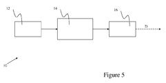
- Figure 5 schematically illustrates the signal flow for the sensor node 10, having sensor element 12, a processing unit 14 (with memory), and a radio link 16.
- the sensor element 12 is capable of sensing the proximity of the objects to be tracked.
- the processing unit 14 determines if an object is present or absent on the basis of the signals from the sensor element 12. If an occupancy status of the detection area of the sensor changes, the processing unit 14 initiates a transmission of a message D indicating the new occupancy status.
- the message may include a time stamp indicative of the time t at which the new occupancy status occurred.
- the sensor nodes may transmit occupancy status information on a periodical basis for example. However, an event-based transmission enables a lower power use.
- the message D sent should reach at least one message interpreter MI.
- a concrete implementation of the sensor node 10 is used for road object tracking: in this case the sensor element 12 is a magnetoresistive component, which measures the disturbance on the earth magnetic field induced by the objects.
- a magnetic rod or loop antenna may be used to detect the occupancy by an object.
- FIG. 6 shows a possible implementation of the hardware involved for the sensor node 10 of Figure 5 .
- the sensor element 12 is coupled via an A/D converter 13 to a microcontroller 14 that has access to a memory 15, and that further controls a radio transmitter 16 coupled to an antenna 17.
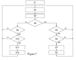
- Figure 7 schematically shows a method performed by a sensor node to generate a message indicative for occupancy status of a detection area of the sensor node.
- Step S1 initialization
- Step S2 input from the A/D converter
- Step S3 offset is removed from the sensed value.
- step S4 it is determined whether the occupancy state of the detection area as reported by the last message transmitted by the sensor node was ON (object was alpresent in the detection range) or OFF (no object present in the detection range. This occupancy state is internally stored in the sensor node.
- step S5 it is determined whether a signal value v obtained from the A/D converter, and indicative for an occupied status of the detection area is below a first predetermined value T L . If this is not the case program flow continues with step S2. If however the value is lower than said first predetermined value then program flow continues with step S6. In step S6 it is verified whether the signal value v remains below the first predetermined value T L for a first predetermined time period. During step S6 the retrieval of input from the A/D convertor is continued. If the signal value v returns to a value higher then said predetermined value T L before the end of said predetermined time-period then processing flow continues with step S2. Otherwise the value for the occupancy state is internally saved as unoccupied in step S7, and a message signaling this is transmitted in step S8.
- step S9 it is determined whether the signal value v obtained from the A/D converter, and indicative for an occupied status of the detection area is above a second predetermined value T H .
- the second predetermined value T H is higher than the first predetermined value T L . If this is not the case program flow continues with step S2. If however the value is higher than said second predetermined value T H then program flow continues with step S10.
- step S 10 it is verified whether the signal value v remains above the second predetermined value T H for a second predetermined time period, which may be equal to the first predetermined time period. During step S10 the retrieval of input from the A/D convertor is continued.
- step S2 If the signal value v returns to a value lower then said predetermined value T H before the end of said predetermined time-period then processing flow continues with step S2. Otherwise the value for the occupancy state is internally saved as occupied in step S11, and a message signaling this is transmitted in step S 12.
- Figure 8 illustrates the signal flow in a message interpreter MI.
- a radio receiver 20 receives the binary "object present" signals D (optionally with timestamp) from the sensor nodes 10 via the radio link and runs a model based state estimator algorithm to calculate the motion states of the objects individually (i.e. each real world object is represented in the message interpreter).
- the sensor density may be chosen dependent on the required accuracy of the estimation. If a very accurate object tracking is desired multiple sensors per object area may be present.
- the message interpreter MI has an object database facility 32, 34 that comprises state information of objects present at the object infrastructure.
- the message interpreter MI further has a sensor map 45describing the spatial location of the sensor nodes 10.
- the sensor nodes may transmit their location, or their position could even be derived by a localization method for wireless sensor networks.
- the message interpreter MI further has an association facility 40 for associating the messages D provided by the sensor nodes 10 with the state information present in the object data base facility 32, 34.
- the association facility 40 may associate the messages received with state information for example with one of the methods Gating, Nearest Neighbor (NN), (Joint) Probabilistic Data Association ((J)DPA), Multiple Hypothesis Tracker (MHT) and the MCMCDA.
- the message interpreter further has a state updating facility 50 for updating the state information on the basis of the messages D associated therewith by the association facility 40. Once the messages D are associated with a particular object the state of that object in a local object data base is updated by the state updating facility 50.
- the association facility 40 and the state updating facility 50 together form a database updating facility DBU.
- a global map builder 65 may exchange this updated information with global map builders of neighboring message interpreters via network interface 60 (wired or wireless) and to receive close to border detections. Other uses are also possible (e.g. to calculate system level features like object density and average velocity, but these are independent from the motion state estimation). , to exchange the motion state of crossing objects.
- a message interpreter MI shown in Figure 9 , consists of a radio receiver 20, coupled to antenna 22, a processing unit 24 (with memory 28) and a network interface 65, as well as a real-time clock 26.
- a real-time clock may be part of the sensor node, and the sensor node may embed a time-stamp indicative for time at which an event was detected in the message.
- a message interpreter will have a more reliable clock, as it can be more reliable synchronized with a reference clock.
- the network interface 65 couples the message interpreter MI via the communication channel 60 to other message interpreters.
- the microcontroller 24 of Figure 9 processes the received messages D.
- the memory 28 stores the local and global object map and the sensor map as well as the software for carrying out the data association and state estimation tasks.
- separate memories may be present for storing each of these maps and for storing the software.
- dedicated hardware may be present to perform one or more of these tasks.
- the result of the processing i.e. the estimation of the motion states of all sensed objects
- the result of the processing is present in the memory of the message interpreters in a distributed way.
- Message interpreters may run additional (cooperative) algorithms to deduct higher level motion characteristics and/or estimate additional object characteristics (e.g. geometry).
- the object tracking system may comprise only a single message interpreter MI.
- MI message interpreter
- the global map builder is superfluous, and local object map is identical to the global object map.
- each message interpreter MI for a respective module comprises hardware as described with reference to Figure 8 and 9 .
- Figure 10 schematically shows a part of an object infrastructure having sections R j-1 , R j , R j+1 .
- an object moves in a direction indicated by arrow X from R j-1 , via Rj, to R j+1 .
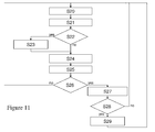
- Figure 11 shows an overview of a method for detecting the object performed by the message interpreter for section R j , using the messages obtained from the sensor nodes.
- step S20 the method waits for a message D from a sensor node.
- program flow continues with step S21, where the time t associated with the message is registered.
- the registered time t associated with the message may be a time-stamp embedded in the message or a time read from an internal clock of the message interpreter.
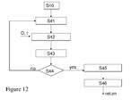
- step S22 it is verified whether the detection is made by a sensor node in a location of section Rj that neighbors one of the neighboring sections R j-1 or R j+1 . If that is the case, then in step S23 the event is communicated via the communication network interface to the message interpreter for that neighboring section. In step S24 it is determined which object O in the object data base facility is responsible for the detected event. An embodiment of a method used to carry out step S24 is described in more detail in Figure 12 . After the responsible object O is identified in Step 25, i.e. an association is made with existing object state information, it is determined in Step 26 whether it is present in the section Rj. If that is the case, control flow continues with Step S27.
- step S28 it is determined whether the state information implies that the object O has a position in a neighboring section R j-1 or R j+1 . In that case the updated state information is transmitted in step S29 to the message interpreter for the neighboring section and control flow returns to step S20. Otherwise the control flow returns immediately to Step S20.
- the current state known for the object with that index i is retrieved from the object database facility.
- a probability is determined that the object O caused the detection reported by the message D at time t.
- the object index i is incremented in step S43 and if it is determined in step S44 that i is less than the number of objects, the steps S41 to S43 are repeated. Otherwise in step S45 it is determined which object caused the detection reported by the message D at time t with the highest probability.
- the index of that object is returned as the result if the method.
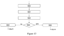
- step S60 the messages D 1 ,...,D n associated with object O are selected.
- step S61 a probability density function is constructed on the basis of the associated messages D 1 ,...,D n .
- step S62 the current state S 0 and time to for object O is retrieved from the object database.
- step S63 it is determined whether the time for which the state S of the object O has to be determined is greater than the time to associated with the current state S 0 .
- the state S (determined by the estimation method) is the state update of S0 to t, performed in step S65. If that is not the case, then the message D relates to a detection preceding the detection that resulted in the earlier estimation for state S0. In that case the state S0 is updated using the detection D by the state estimation method in step S64.
- A1 Estimation and association for multiple target tracking based on spatially, distributed detections
- multiple target tracking [1-3] one aims to track all the objects/targets, which are moving in a certain area.
- Section 2 defines background knowledge such as the notation of (object) variables and functions that are used throughout this paper. After that the problem is formulated in section 3 together with existing methods. Section 4 describes the approach which is taken in the design. A more detailed description of the estimation and associated is presented in Section 5 and 6 respectively. Finally both methods are tested in a small application example presented in Section 6 and conclusions are drawn in section 7. But let's start with the background information.
- the set Z defines the integer values and defines the set of non-negative integer numbers.
- the variable 0 is used either as null, the null-vector or the null-matrix. Its size will become clear from the context.
- Vector x ( t ) ⁇ is defined as a vector depending on time t and is sampled using some sampling method.
- the time t at sampling instant k ⁇ is defined as t k ⁇ .
- the matrix A ( t 2 - t 1 ) ⁇ depends on the difference between two time instants t 2 > t 1 and is shortly denotes as A t 2 - t 1
- each object also has a certain shape or geometry which covers a certain set of positions in , i.e. the grey area of Figure 14 .
- To define the vectors ⁇ i we equidistant sample the rectangular box defined by using a grid with a distance r .
- Each ⁇ i is a grid point within the set S as graphically depicted in Figure 15 .
- T i represents the i th object's rotation-matrix dependent on ⁇ i .
- the objects are observed in by a camera or a network of sensors. For that M 'detection' points are marked within and collected in the set D ⁇ .
- the position of a detection point is denoted as d ⁇ D .
- Figure 16 shows an example of object i which is detected by multiple detection points. The covariance ⁇ of each detection point is also indicated.
- the sampling method of the observation vectors z 0: k s a form of event sampling [4, 5,7]. For a new observation vector is sampled whenever an event, i.e. object detection, takes place. With these event samples all N objects are to be tracked. To accomplish that three methods are needed. The first one is the association of the new observation-vector z k to an object i and therefore denote it with z k i . Suppose that all associated observation-vectors z n i are collected in the set z k i ⁇ z 0 : k . Then the second method is to estimate m k i from the observation-set Z k i . This is used in the third method, which is a state-estimator.
- Z k i is defined as the set with all observation-vectors from z 0: k that were associated with object i .
- Z k i is defined as the set with all observation-vectors from z 0: k that were associated with object i .
- the set Z k i ⁇ z 0 : k is defined as the set of all observation-vectors z n which were associated with object i , from which their detection point is still covered by the object. We will first show how this is done. At time step k we have the observation-set Z k - 1 i and the observation z k was associated to object i , i.e. z k i . Now if the object's edge is detected at d k for the first time, then z k i is added to the set Z k - 1 i .
- Z k i is defined as: Z k i : ⁇ Z k - 1 i ⁇ z k , if d k ⁇ d n , ⁇ z n i ⁇ Z k - 1 i , Z k - 1 i ⁇ z n , if ⁇ n
- Estimation of the measurement-vector m k i given the observation set Z k i results in calculating p m k i
- the set Z consists of the observation vectors z n , for all n ⁇ N ⁇ [0, k ], that were associated to the same object.
- the detection point at time-step n are defined as d n ⁇ . Meaning that the objects orientation is not directly.
- Z ) is approximated by sampling in ⁇ , i.e.: p m
- the main aspect of equation (13a) is to determine p ( o
- O n ( ⁇ ) ⁇ to be equal to all possible object positions o , given that the object is detected at position d n ⁇ z n ( ⁇ Z ) and that the object's rotation is equal to ⁇ .
- Z , ⁇ ) and ⁇ l are related to the set O N ( ⁇ ) due to the fact that it O N ( thet a ) defines the set of possible object positions o for a given ⁇ .
- Z , ⁇ ) f o
- z n , ⁇ : ⁇ 0 if o ⁇ O N ⁇ , 1 if o ⁇ O n ⁇ , g o
- Z , ⁇ : ⁇ n ⁇ N ⁇ f o
- z n , ⁇ ⁇ 0 if o ⁇ O N ⁇ , 1 if o ⁇ O N 0 ,
- Z ) is calculated according to (13).
- the rest of this section is divided into two parts. The first part derives the probability function based on a single detection, i.e. f ( o
- Figure 20 (right) graphically depicts the determination of ⁇ n from the set ⁇ for a given ⁇ and detection point d n .
- z n , ⁇ ), as defined in (15), is approximated by placing a Gaussian function at each sampled position ô i ⁇ ⁇ n with a certain covariance dependent on the grid-size r : f o
- the aim of this section is to calculate the function g ( o
- Equation (22) If N contains m elements, then calculating equation (22) would result in K m products of m Gaussian functions and sum them afterwards. This would take too much processing power if m is large. That is why equation (22) is calculated differently.
- each detection point d n defines a rectangular set denoted with ( ⁇ ) dependent on rotation ⁇ .
- the intersection of all these rectangular sets is defined with the set ( ⁇ ).
- the first set, O n ( ⁇ ),shown in Figure 17 defines all possible object positions o based on a single detection at d n .
- the second set, i.e. O N ( ⁇ ),shown in Figure 18 defines all possible object positions o based on all detections at d n , ⁇ n ⁇ N .
- Z , ⁇ ) of (22) is therefore approximated as: g o
- Z , ⁇ ⁇ ⁇ n ⁇ N 2 ⁇ ⁇ ⁇ ⁇ 2 ⁇ i I n G o ⁇ o ⁇ i n ⁇ R , with I n : ⁇ o ⁇ i n - C N ⁇ ⁇ ⁇ ⁇ + ⁇ , ⁇ i ⁇ I j .
- Equation (25) is reduced to: g o
- Z , ⁇ ⁇ ⁇ n N 2 ⁇ ⁇ ⁇ ⁇ 2 ⁇ i ⁇ I n G o ⁇ o ⁇ i n ⁇ R , with N ⁇ N : C N ⁇ ⁇ O n ⁇ , ⁇ n ⁇ N ⁇ N .
- the calculation of (26) is done by applying the following two propositions.
- the first one i.e. Proposition 2
- the second one i.e. Proposition 3, proofs that a product of Gaussians results in a single Gaussian.
- Proposition 2 The product of a summation of Gaussians can be written into a summation of a product of Gaussian :
- the proof is given by writing out the left hand side of (27a) and restructuring it.
- Equation (30) is substituted into equation (16) together with g ( o
- Z ) also gives us the probability that a new observation vector is generated by an certain object i . This is discussed in the next section.
- the total probability that a new observation vector z k is generated by object i is equal to the total probability of the measurement-vector m k i given the observation set Z k - 1 i ⁇ z k .
- Z k - 1 i , z k which is equal to equation (31).
- the definition of a PDF is that its total probability, i.e. its integral from - ⁇ to ⁇ , is equal to 1.
- ⁇ i and K i are equal to ⁇ and K respectively, which define the approximation of the function f ( m k i
- the probability of (32) one can design a method which associates an observation-vector due to a new detection, to its most probable object i.
- the estimation method requires a certain amount of processing power, one can reduce this by reducing the number of samples in the set ⁇ . Meaning that association and estimation can be done with different sizes of ⁇ .
- the objects have a rectangular shape, then with some tricks one can reduce the amount of processing power to a level at which both association as well as estimation can run real-time.
- the simulation case is made such that it contains two interesting situation.
- the objects are tracked using two different association methods.
- the first one is a combination of Gating and detection association of 6.
- the second one is a combination of Gating and Nearest Neighbor.
- This paper presents a method for estimating the position- and rotation-vector of objects from spatially, distributed detections of that object. Each detection is generated at the event that the edge of an object crosses a detection point. From the estimation method a detection associator is also designed. This association method calculates the probability that a new detection was generated by an object i .
- An example of a parking lot shows that the detection association method has no incorrect associated detections in the case that two vehicles cross each other both in parallel as well as orthogonal. If the association method of Nearest Neighbor was used, a large amount of incorrect associated detections were noticed, resulting in a higher state-estimation error.
- the data-assimilation can be further improved with two adjustments.
- the first one is replacing the set S with S E only at the time-instants that the observation vector is received.
- the second improvement is to take the detection points that have not detected anything also in account.
- x ⁇ p x ⁇ dx ⁇ - ⁇ ⁇ ⁇ G m ⁇ ⁇ x ⁇ M ⁇ G x ⁇ u ⁇ U ⁇ dx .
- R defines the set of real numbers whereas the set defines the non-negative real numbers.
- the set Z defines the integer numbers and defines the set of non-negative integer numbers.
- the notation 0 is used to denote either the null-vector or the null-matrix. Its size will become clear from the context.
- a vector x ( t ) ⁇ is defined to depend on time t ⁇ and is sampled using some sampling method. Two different sampling methods are discussed. The first one is time sampling in which samples are generated whenever time t equals some predefined value. This is either synchronous in time or asynchronous. In the synchronous case the time between two samples is constant and defined as t s ⁇ .
- the i th and maximum eigenvalue of a square matrix A are denoted as ⁇ i ( A ) and ⁇ max ( A ) respectively.
- a ⁇ and B ⁇ are positive definite, denoted with A ⁇ 0 and B ⁇ 0, then A ⁇ B denotes A - B ⁇ 0.
- a ⁇ 0 denotes A is positive semi-definite.
- PDF probability density function
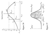
- the exact description of the set H ke ( Z ke -1, t ) depends on the actual sampling method. As an example H ke ( z ke -1 , t ) is derived for the method "Send-on-Delta", with y ( t ) ⁇ .
- H ke ( z ke -1 , t ) should contain the set of all possible values that y ( t ) can take in between the event instants k e - 1 and K e . Meaning that if t ke -1 ⁇ t ⁇ t ke , then y ( t ) ⁇ H ke ( z ke -1 , t ).
- the state vector x ( t ) of this system is to be estimated from the observation vectors z 0e: ke .
- our goal is to construct an event-based state-estimator (EBSE) that provides an estimate of x ( t ) not only at the event instants t ke but also at the sampling instants t ka . Therefore, we define a new set of sampling instants t n as the combination of sampling instants due to event sampling, i.e.
- the estimator calculates the PDF of the state-vector x n given all the observations until t n . This results in a hybrid state-estimator, for at time t n an event can either occur or not, which further implies that measurement data is received or not, respectively. In both cases the estimated state must be updated (not predicted) with all information until t n .
- n define the shape of this Gaussian function. Together with x n
- the problem of interest in this paper is to construct a state-estimator suitable for the general event sampling method introduced in Section 3 and which is computationally tractable. Furthermore, it is desirable to guarantee that P n
- Existing state estimators can be divided into two categories.
- the first one contains estimators based on time sampling: the (a)synchronous Kalman filter [12, 13] (linear process, Gaussian PDF), the Particle niter [14] and the Gaussian sum filter [4,5] (nonlinear process, non-Gaussian PDF).
- These estimators cannot be directly employed in event based sampling as if no new observation vector z ke is received, then t n - t ke ⁇ ⁇ and ⁇ i ( P n
- the second category contains estimators based on event sampling. In fact, to the best of our knowledge, only the method proposed in [15] fits this category.
- Equation (25) is explicitly solved by applying Proposition 1: p ⁇ x n
- n - 1 + C T ⁇ R n i - 1 ⁇ y n i , P n i : P n
- n - 1 - 1 + C T ⁇ R n i - 1 ⁇ C - 1 and ⁇ n i : G ⁇ y n i , C ⁇ x n
- y 0: n ⁇ Y 0 : n ) of (27) is approximated as a single Gaussian with an equal expectation and covariance matrix, i.e.: p x n
- the first two estimators are the EBSE and the asynchronous Kalman filter (AKF) of [13].
- ⁇ 0.1 [ m ].
- the AKF estimates the states only at the event instants t ke .
- the states at t ka are calculated by applying the prediction-step of (14b).
- the third estimator is based on the quantized Kalman filter (QKF) introduced in [21] that uses synchronous time sampling of y ka .
- the QKF can deal with quantized data, which also results in less data transfer, and therefore can be considered as an alternative to EBSE.
- y ka is the quantized version of y ka with quantization level 0.1, which corresponds to the "Send-on-Delta" method. Hence, a comparison can be made.
- ⁇ ⁇ R + x i - x i
- i - 1 , which is a measure of the change in the estimation-error after the measurement update with either z ke or y ka was done. Notice that if ⁇ ⁇ 1 the estimation error decreased after an update, if ⁇ > 1 the error increased and if ⁇ 1 the error remained the same.
- the last aspect on which the three estimators are compared is the total amount of processing time which was needed to estimate all state-vectors.
- both x ke and x ka were estimated and it took 0.094 seconds.
- the EBSE calculates P n
- n 2 as (29) in which V is replaced with R : V + V . Notice that for these estimators we have that ⁇ n ⁇ t s and R n ⁇ R , for all n . Let the EBSE and the KF start with the same initial covariance matrix P 0 .
- the first step of induction is to prove that From the definition of P 1
- 1 1 A ⁇ 1 ⁇ P 0 ⁇ A ⁇ 1 T + B ⁇ 1 ⁇ Q ⁇ B ⁇ 1 T - 1 + C T ⁇ R 1 - 1 ⁇ C - 1 and P 1
- 1 2 A t s ⁇ P 0 ⁇ A t s T + B t s ⁇ Q ⁇ B t s T - 1 + C T ⁇ R - 1 ⁇ C - 1 .
- V 1 A ⁇ 1 ⁇ P 0 ⁇ A ⁇ 1 T + B ⁇ 1 ⁇ Q ⁇ B ⁇ 1 T
- V 2 A t s ⁇ P 0 ⁇ A t s T + B t s ⁇ Q ⁇ B t s T
- 1 1 and U 2 : P 1
Landscapes
- Chemical & Material Sciences (AREA)
- Analytical Chemistry (AREA)
- Physics & Mathematics (AREA)
- General Physics & Mathematics (AREA)
- Traffic Control Systems (AREA)
- Radar Systems Or Details Thereof (AREA)
Priority Applications (3)
| Application Number | Priority Date | Filing Date | Title |
|---|---|---|---|
| EP08171580A EP2196972A1 (de) | 2008-12-12 | 2008-12-12 | Objektverfolgungssystem, Objektinfrastruktur, die mit einem Objektverfolgungssystem versehen ist, und Verfahren zur Verfolgung von Objekten |
| EP09771423.2A EP2374117B1 (de) | 2008-12-12 | 2009-12-11 | Objektverfolgungssystem, objektinfrastruktur, die mit einem objektverfolgungssystem versehen ist, und verfahren zur verfolgung von objekten |
| PCT/NL2009/050758 WO2010068106A1 (en) | 2008-12-12 | 2009-12-11 | Vehicle tracking system, vehicle infrastructure provided with vehicle tracking system and method for tracking vehicles |
Applications Claiming Priority (1)
| Application Number | Priority Date | Filing Date | Title |
|---|---|---|---|
| EP08171580A EP2196972A1 (de) | 2008-12-12 | 2008-12-12 | Objektverfolgungssystem, Objektinfrastruktur, die mit einem Objektverfolgungssystem versehen ist, und Verfahren zur Verfolgung von Objekten |
Publications (1)
| Publication Number | Publication Date |
|---|---|
| EP2196972A1 true EP2196972A1 (de) | 2010-06-16 |
Family
ID=40756284
Family Applications (2)
| Application Number | Title | Priority Date | Filing Date |
|---|---|---|---|
| EP08171580A Withdrawn EP2196972A1 (de) | 2008-12-12 | 2008-12-12 | Objektverfolgungssystem, Objektinfrastruktur, die mit einem Objektverfolgungssystem versehen ist, und Verfahren zur Verfolgung von Objekten |
| EP09771423.2A Active EP2374117B1 (de) | 2008-12-12 | 2009-12-11 | Objektverfolgungssystem, objektinfrastruktur, die mit einem objektverfolgungssystem versehen ist, und verfahren zur verfolgung von objekten |
Family Applications After (1)
| Application Number | Title | Priority Date | Filing Date |
|---|---|---|---|
| EP09771423.2A Active EP2374117B1 (de) | 2008-12-12 | 2009-12-11 | Objektverfolgungssystem, objektinfrastruktur, die mit einem objektverfolgungssystem versehen ist, und verfahren zur verfolgung von objekten |
Country Status (2)
| Country | Link |
|---|---|
| EP (2) | EP2196972A1 (de) |
| WO (1) | WO2010068106A1 (de) |
Cited By (1)
| Publication number | Priority date | Publication date | Assignee | Title |
|---|---|---|---|---|
| US7991550B2 (en) * | 2006-02-03 | 2011-08-02 | GM Global Technology Operations LLC | Method and apparatus for on-vehicle calibration and orientation of object-tracking systems |
Families Citing this family (1)
| Publication number | Priority date | Publication date | Assignee | Title |
|---|---|---|---|---|
| CN110542885B (zh) * | 2019-08-13 | 2021-09-21 | 北京理工大学 | 一种复杂交通环境下的毫米波雷达目标跟踪方法 |
Citations (4)
| Publication number | Priority date | Publication date | Assignee | Title |
|---|---|---|---|---|
| US5801943A (en) * | 1993-07-23 | 1998-09-01 | Condition Monitoring Systems | Traffic surveillance and simulation apparatus |
| US20010010541A1 (en) * | 1998-03-19 | 2001-08-02 | Fernandez Dennis Sunga | Integrated network for monitoring remote objects |
| WO2001078397A1 (en) * | 2000-04-11 | 2001-10-18 | Safehouse International Limited | An object monitoring system |
| WO2006068463A1 (en) * | 2004-12-24 | 2006-06-29 | Ultrawaves Design Holding B.V. | Intelligent distributed image processing |
-
2008
- 2008-12-12 EP EP08171580A patent/EP2196972A1/de not_active Withdrawn
-
2009
- 2009-12-11 EP EP09771423.2A patent/EP2374117B1/de active Active
- 2009-12-11 WO PCT/NL2009/050758 patent/WO2010068106A1/en not_active Ceased
Patent Citations (4)
| Publication number | Priority date | Publication date | Assignee | Title |
|---|---|---|---|---|
| US5801943A (en) * | 1993-07-23 | 1998-09-01 | Condition Monitoring Systems | Traffic surveillance and simulation apparatus |
| US20010010541A1 (en) * | 1998-03-19 | 2001-08-02 | Fernandez Dennis Sunga | Integrated network for monitoring remote objects |
| WO2001078397A1 (en) * | 2000-04-11 | 2001-10-18 | Safehouse International Limited | An object monitoring system |
| WO2006068463A1 (en) * | 2004-12-24 | 2006-06-29 | Ultrawaves Design Holding B.V. | Intelligent distributed image processing |
Non-Patent Citations (35)
| Title |
|---|
| "Asymptotic Effectiveness of the Event-Based Sampling according to the Integral Criterion", SENSORS, vol. 7, 2007, pages 16 - 37 |
| A. POORE; S. GADALETA: "Some assignment problems arising from multiple target tracking", MATHEMATICAL AND COMPUTER MODELLING, vol. 43, 2006, pages 1074 - 1091, XP024904058, DOI: doi:10.1016/j.mcm.2005.05.026 |
| A. V. BALALTRISHNAN, KALMAN FILTERING THEORY. OPTIMIZATION SOFTWARE, 1987 |
| B. RISTIC; S. ARULAMPALAM; N. GORDON, BEYOND THE KALMAN FILTER: PARTICLE FILTER FOR TRACKING APPLICATIONS, 2002 |
| B. RISTIC; S. ARULAMPALUM; N. GORDON, BEYOND THE KALMAN FILTER: PARTICLE FILTER FOR TRACKING APPLICATIONS. BOSTON, MASSACHUSETTS: ARTECH HOUSE, 2004 |
| D. C. MONTGOMERY; G. C. RUNGER: "Applied Statistics and Probability forEngineers", 2007, JOHN WILEY AND SONS |
| D. KELLY: "Introduction to probability", 1994, MACMILLAN PUBLISHING COMPANY |
| D. S. BERNSTEIN: "Matrix Mathernatics", 2005, PRINCETON UNIVERSITY PRESS |
| E. JOHANNESSON; T. HENNINGSSON; A. CERVIN: "Hybrid Systems: Computation and Control, ser. Lecture Notes in Computer Science", vol. 4416, 2007, SPRINGER VERLAG, article "Sporadic control of first-order linear stochastic systems", pages: 301 - 314 |
| G. F. FRANKLIN; J. D. POWEL; A. EMAMI-NAEINI: "Feedback control of dynamic systems", 1995 |
| H. DURANT-WHYTE; B. RAO; H. HU: "Towards a fully decentralized architecture for multisensor data fusion", 1990 IEEE INT. CONF. ON ROBOTICS AND AUTOMATION, 1990, pages 1331 - 1336 |
| H. L. LEBESQUE: "Integrale, longueur, aire", PH.D. DISSERTATION, 1902 |
| H. W. SORENSON; D. L. ALSPACH: "Recursive Bayesian estimation using Gaussian sums", AUTOMATICA, vol. 7, 1971, pages 465 - 479 |
| I. F. AKYILDIZ ET AL.: "Computer Networks", vol. 38, 2002, ELSEVIER, article "Wireless Sensor Networks: a survey", pages: 393 - 422 |
| J. H. KOTECHA; P. M. DJURI: "Gaussian sum particle filtering", IEEE TRANSACTION SIGNAL PROCESSING, vol. 51, no. 10, 2003, pages 2602 - 2612 |
| K. ÅSTRÖM; B. BERNHARDSSON: "Comparison of Riemann and Lebesque sampling for first order stochastic systems", 41ST IEEE CONFERENCE ON DECISION AND CONTROL, 2002 |
| K. J. ASTRÖM; B. M. BEMHARDSSON: "Comparison of Riemann and Lebesque sampling for first order stochastic systems", 41ST IEEE CONF ON DEC. AND CONTR., 2002 |
| K. MARDIA; J. KENT; J. BIBBY: "Mutlivariate analysis", 1979, ACADEMIC PRESS, INC |
| K. V MARDIA; J. T. KENT; J. M. BIBBY: "Mutlivariate analysis", 1979, ACADEMIC PRESS |
| L. AGGOUN; R. ELLIOT: "Measure Theory and Filtering", 2004, CAMBRIDGE UNIVERSITY PRESS |
| M. L. J. HAUTUS: "Controllability and observability conditions of linear autonomous systems", INDAGATIONES MATHEMATHICAE, vol. 32, 1972, pages 448 - 455 |
| M. MALLICK; S. CORALUPPI; C. CARTHEL: "Advances in Asynchronous and Decentralized Estimation", PROCEEDING OF THE 2001 AEROSPACE CONFERENCE, 2001 |
| M. MISKOWICZ: "Send-on-delta concept: an event-based data-reporting strategy", SENSORS, vol. 6, 2006, pages 49 - 63, XP055179444, DOI: doi:10.3390/s6010049 |
| N. JOHNSON; S. KOTZ; A. KEMP: "Univariate discrete distributions", 1992, JOHN WILEY AND SONS, INC |
| N. L. JOHNSON; S. KOTZ; A. W. KEMP: "Univariate discrete distributions", 1992, JOHN WILEY AND SONS |
| O. SONGHWAI; S. SASTRY; L. SCHENATO: "A Hierarchical Multiple-Target Tracking Algorithm for Sensor Networks", PROC. OF THE 2005 IEEE INTERNATIONAL CONFERENCE ON ROBOTICS AND AUTOMATION, 2005 |
| PETER J. BICKEL: "Measuring Traffic", STATISTICAL SCIENCE, vol. 22, no. 4, 2007, pages 581 - 597 |
| R. E. CURRY: "Estimation and control with quantized measurements", 1970, MIT PRESS |
| R. E. KALMAN: "A new approach to linear filtering and prediction problems", TRANSACTION OF THE ASME JOURNAL OF BASIC ENGINEERING, vol. 82, 1960, pages 35 - 42 |
| R. KARLSSON; F. GUSTAFSSON: "Monte Carlo data association for multiple target tracking", IEE INTERNATIONAL SEMINAR ON TARGET TRACKING: ALGORITHMS AND APPLICATIONS, 2001 |
| S. BLACKMAN; R. POPOLI, DESIGN AND ANALYSIS OF MODEM TRACKING SYSTEMS, 1999 |
| V. H. NGUYEN; Y. S. SUH: "Improving estimation performance in Networked Control Systems applying the Send-on-delta transmission method", SENSORS, vol. 7, 2007, pages 2128 - 2138 |
| V. NGUYEN; Y SUH: "Improving estimation performance in Networked Control Systems applying the Send-on-delta transmission method", SENSORS, vol. 7, 2007, pages 2128 - 2138 |
| W. P. M. H. HEEMELS; J. H. SANDEE; P. P. J. VAN DEN BOSCH: "Analysis of event-driven controllers for linear systems", INTERNATIONAL JOURNAL OF CONTROL, vol. 81, no. 4, 2008 |
| Y BAR-SHALOM; R. LI, MULTITARGET-MULTISENSOR TRACKING: PRINCIPLES AND TECHNIQUES. YBS, 1995 |
Cited By (1)
| Publication number | Priority date | Publication date | Assignee | Title |
|---|---|---|---|---|
| US7991550B2 (en) * | 2006-02-03 | 2011-08-02 | GM Global Technology Operations LLC | Method and apparatus for on-vehicle calibration and orientation of object-tracking systems |
Also Published As
| Publication number | Publication date |
|---|---|
| EP2374117A1 (de) | 2011-10-12 |
| EP2374117B1 (de) | 2017-08-30 |
| WO2010068106A1 (en) | 2010-06-17 |
Similar Documents
| Publication | Publication Date | Title |
|---|---|---|
| EP2370965B1 (de) | Verkehrsinformationseinheit, verkehrsinformationssystem, fahrzeugverwaltungssystem, fahrzeug und verfahren zum steuern eines fahrzeugs | |
| Li et al. | Split covariance intersection filter: Theory and its application to vehicle localization | |
| Zhang et al. | Vehicle re-identification for lane-level travel time estimations on congested urban road networks using video images | |
| CN105467382A (zh) | 基于svm的多传感器的目标跟踪数据融合算法及其系统 | |
| Wang et al. | Vehicle trajectory prediction algorithm in vehicular network | |
| Lee et al. | Density-aware decentralised multi-agent exploration with energy constraint based on optimal transport theory | |
| Ghods et al. | Real-time estimation of turning movement counts at signalized intersections using signal phase information | |
| Seo et al. | Online target localization using adaptive belief propagation in the HMM framework | |
| Farag | Bayesian localization in real-time using probabilistic maps and unscented-kalman-filters | |
| EP2374117B1 (de) | Objektverfolgungssystem, objektinfrastruktur, die mit einem objektverfolgungssystem versehen ist, und verfahren zur verfolgung von objekten | |
| Ng et al. | LoRa-based indoor positioning in dynamic industrial environments using deep Gaussian process regression and temporal-based enhancements | |
| Xiao et al. | Augmented extended Kalman filter with cooperative Bayesian filtering and multi‐models fusion for precise vehicle localisations | |
| Edelmayer et al. | Cooperative federated filtering approach for enhanced position estimation and sensor fault tolerance in ad-hoc vehicle networks | |
| Worrall et al. | A probabilistic method for detecting impending vehicle interactions | |
| Piperigkos et al. | Robust cooperative sparse representation solutions for detecting and mitigating spoofing attacks in autonomous vehicles | |
| Barde et al. | A survey of multi-sensor data fusion in wireless sensor networks | |
| Baek et al. | Method for estimating population OD matrix based on probe vehicles | |
| Claessens et al. | Context driven tracking using particle filters | |
| Nantes et al. | Bayesian inference of traffic volumes based on Bluetooth data | |
| Yakubovich et al. | A methodology for optimizing the objective function in a high-dimensional space using the swarm intelligence algorithm | |
| Piperigkos et al. | Cooperative plug-and-play-KalmanNet for 4D situational awareness in autonomous driving | |
| Piperigkos et al. | 5G enabled cooperative localization of connected and semi-autonomous vehicles via sparse Laplacian processing | |
| Sengupta et al. | Newell's theory based feature transformations for spatio-temporal traffic prediction | |
| Hongsheng | Far-field sensing in partial VANET environment | |
| Guo et al. | Cooperative Vehicle Localization in VANETs Subject to Sensing and Transmission Failures |
Legal Events
| Date | Code | Title | Description |
|---|---|---|---|
| PUAI | Public reference made under article 153(3) epc to a published international application that has entered the european phase |
Free format text: ORIGINAL CODE: 0009012 |
|
| AK | Designated contracting states |
Kind code of ref document: A1 Designated state(s): AT BE BG CH CY CZ DE DK EE ES FI FR GB GR HR HU IE IS IT LI LT LU LV MC MT NL NO PL PT RO SE SI SK TR |
|
| AX | Request for extension of the european patent |
Extension state: AL BA MK RS |
|
| AKY | No designation fees paid | ||
| REG | Reference to a national code |
Ref country code: DE Ref legal event code: 8566 |
|
| STAA | Information on the status of an ep patent application or granted ep patent |
Free format text: STATUS: THE APPLICATION IS DEEMED TO BE WITHDRAWN |
|
| 18D | Application deemed to be withdrawn |
Effective date: 20101217 |