EP2196844A1 - A projection unit having a speckle suppression device based on piezoelectric actuating - Google Patents
A projection unit having a speckle suppression device based on piezoelectric actuating Download PDFInfo
- Publication number
- EP2196844A1 EP2196844A1 EP09154420A EP09154420A EP2196844A1 EP 2196844 A1 EP2196844 A1 EP 2196844A1 EP 09154420 A EP09154420 A EP 09154420A EP 09154420 A EP09154420 A EP 09154420A EP 2196844 A1 EP2196844 A1 EP 2196844A1
- Authority
- EP
- European Patent Office
- Prior art keywords
- projection unit
- suppression device
- speckle suppression
- display
- diffusing element
- Prior art date
- Legal status (The legal status is an assumption and is not a legal conclusion. Google has not performed a legal analysis and makes no representation as to the accuracy of the status listed.)
- Granted
Links
Images


Classifications
-
- G—PHYSICS
- G02—OPTICS
- G02B—OPTICAL ELEMENTS, SYSTEMS OR APPARATUS
- G02B27/00—Optical systems or apparatus not provided for by any of the groups G02B1/00 - G02B26/00, G02B30/00
- G02B27/48—Laser speckle optics
-
- G—PHYSICS
- G02—OPTICS
- G02B—OPTICAL ELEMENTS, SYSTEMS OR APPARATUS
- G02B27/00—Optical systems or apparatus not provided for by any of the groups G02B1/00 - G02B26/00, G02B30/00
- G02B27/01—Head-up displays
-
- G—PHYSICS
- G02—OPTICS
- G02B—OPTICAL ELEMENTS, SYSTEMS OR APPARATUS
- G02B27/00—Optical systems or apparatus not provided for by any of the groups G02B1/00 - G02B26/00, G02B30/00
- G02B27/01—Head-up displays
- G02B27/0101—Head-up displays characterised by optical features
-
- H—ELECTRICITY
- H04—ELECTRIC COMMUNICATION TECHNIQUE
- H04N—PICTORIAL COMMUNICATION, e.g. TELEVISION
- H04N9/00—Details of colour television systems
- H04N9/12—Picture reproducers
- H04N9/31—Projection devices for colour picture display, e.g. using electronic spatial light modulators [ESLM]
- H04N9/3141—Constructional details thereof
- H04N9/315—Modulator illumination systems
- H04N9/3161—Modulator illumination systems using laser light sources
-
- G—PHYSICS
- G02—OPTICS
- G02B—OPTICAL ELEMENTS, SYSTEMS OR APPARATUS
- G02B5/00—Optical elements other than lenses
- G02B5/02—Diffusing elements; Afocal elements
Definitions
- the present invention relates to a laser based projection unit for diffractive head up display having a laser speckle suppression device based on piezoelectric actuating.
- Diffractive head up displays use coherent type light source in order to illuminate a display, and then to project a virtual image through a diffractive combiner.
- the usage of diffractive technology in this kind of application implies a necessity to have an adapted projection unit able to interact correctly with the diffractive combiner especially concerning the image quality.
- speckle appears when we illuminate a display or a naturally rough surface with a light spatially and temporally coherent as the light generated by a laser source. This phenomenon can be useful for certain applications such as measuring deformation of objects. But in other applications such as projection systems, including those associated with head-up display application using diffractive components, the suppression of this phenomenon is very important to improve the quality of the virtual image perceived by user.
- the statistical properties of the speckle generally depend from one hand on the coherence of the incident beam and on the other hand on the diffused mediums crossed by the light beam.
- the average size of speckle depends also on the optical system used after the display (lens, diffractive combiner and in some cases human eye).
- the purpose of the present invention is to give a solution to all the above described limitations of speckle reduction devices, by proposing a simple and small instrument for speckle reduction that can be integrated in any projection system without any need to modify the optical design of the projection system. Also the purpose of the present invention is a laser based projection system having the proposed speckle suppression device.
- the present invention proposes a projection unit for diffractive head up display comprising a coherent light source such as a laser diode and a beam shaping element forming a light beam which is directed towards a display, characterized in that it comprises a laser speckle suppression device which is positioned between the laser source and the display and wherein the laser speckle suppression device is a diffusing element actuated randomly by a piezoelectric vibrating structure.
- the speckle suppression device presented in the invention is based on moving directly a diffusing medium according to a composite vibration mode.
- This composite vibration mode for example bending+ rotation or + shearing
- This composite vibration mode associated with the structural features of the diffuser will enable to generate for each position of the diffuser a corresponding wavefront and thus a special speckle noise.
- the averaging of these wavefronts will enable a real random spatial phase averaging, which can reduce the speckle, whatever its magnitude, and at the same time to correct the uniformity of the beam.
- the projection unit 10 is constituted of a laser type source 12 generating a coherent light beam, a beam shaping element 14 (diffractive or not) and a display 16.
- a laser speckle suppression device 18 is positioned between the laser source 12 and the display 16.
- the laser speckle suppression device 18 is constituted of a vibrating metallic structure 20 on which an optical diffusing element 22 is fixed through which the laser beam 24 passes. Piezoelectric plates 26 are fixed on the vibrating structure 20. An electronic oscillating circuit 28 is designed to drive the vibrations in the piezoelectric elements at the desired frequency and at the desired vibration mode. This method enables to apply directly a vibrating movement to the diffusing element 22.
- the laser speckle suppression device 18 is constituted of a quartz plate 30 on which a diffusion layer 32 is deposited. Electrodes 34 are directly deposited on the quartz plate surfaces. These electrodes 34 are used in order to generate the required vibrating modes at the required frequency.
- the quartz plate is fixed for example on a support surface 36 on the electronic PCB including the driving electronics 28.
- This embodiment uses directly the piezoelectric properties of the quartz in order to generate the required vibrating modes at the desired frequency, and enables a simple integration with the associated driving electronics 28.
- the optical characteristics of the quartz plate 30 transparent material with a refraction index about 1.458
- the speckle is reduced due to the random averaging of the phase, and also the uniformization of the beam is obtained.
- the electronic circuit 28 is designed in order to assure the vibration of the structure at the required vibration frequency. In fact, this frequency is related to the chosen vibrating mode.
- the vibration of the diffusing element 22 randomly averages the image and thus reduces the speckle by virtually creating a mean value of the laser wavelength. Generally it is enough to drive the vibration at a frequency higher than that of the human eye sensitivity with sufficient amplitude. The random vibrations at that frequency will enable the eye to see a mean value of the images superposed on the diffusing element 22.
- the piezoelectric actuating according to the present invention is specifically designed to generate the composite vibration mode at the desired frequency and amplitude, the frequency is chosen with respect to the eye sensitivity criterion and to comfort requirements (no audible noise is generated by the device).
- This kind of projection systems 10 having such speckle suppression device 18 can be suitable for application such as head up displays based on diffractive (or holographic) combiners.
- head up displays based on diffractive (or holographic) combiners.
- the speckle effect is generally magnified by the diffractive combiner.
- the projection unit 10 for the diffractive head up display 42 presented on figure 7 comprises a laser source 12, a diffractive beam shaping element 14, two mirrors 38, 40, and a display 16.
- the diffractive beam shaping element 14 is designed to obtain a light spot having the same shape and dimensions as the display 16 with a high uniformity and a high energetic efficiency.
- the laser speckle suppression device 18 shown corresponds to the first embodiment of the invention.
- the laser speckle suppression device 18 can be easily integrated within the projection unit 10 and within the head up display 42 without any need to modify the optical design initially defined.
Abstract
Description
- The present invention relates to a laser based projection unit for diffractive head up display having a laser speckle suppression device based on piezoelectric actuating.
- Diffractive head up displays use coherent type light source in order to illuminate a display, and then to project a virtual image through a diffractive combiner. The usage of diffractive technology in this kind of application implies a necessity to have an adapted projection unit able to interact correctly with the diffractive combiner especially concerning the image quality.
- The phenomenon of speckle appears when we illuminate a display or a naturally rough surface with a light spatially and temporally coherent as the light generated by a laser source. This phenomenon can be useful for certain applications such as measuring deformation of objects. But in other applications such as projection systems, including those associated with head-up display application using diffractive components, the suppression of this phenomenon is very important to improve the quality of the virtual image perceived by user.
- As mentioned above, the statistical properties of the speckle generally depend from one hand on the coherence of the incident beam and on the other hand on the diffused mediums crossed by the light beam. In a projection system, including systems used in head-up display based on diffractive elements, the average size of speckle depends also on the optical system used after the display (lens, diffractive combiner and in some cases human eye).
- Up to today, almost all the currently patented speckle reduction devices uses complex optical systems and requires precise adjustments that can not be easily implemented for industrial application. We cite for example patents
U.S. 4,155,630 ;US2008/0055698A1 ;WO 00/65401 EP1257869 B1 . - All these are based on averaging of phase (case of patents
U.S. 4,155,630 ;US2008/0055698A1 and) using rocking motion of a mirror; or on averaging the polarization of the light beam (case ofEP1257869 B1 ). In all cases the usage of mirrors presents many limitations: - The application of a movement of translation or tilting on the mirror involves only a translation of wave front. In other words the averaging is done on several identical shifted wave fronts, this averaging reduces slightly the speckle but has no effect on the uniformization of the beam.
- The usage of mirrors requires a very precise control to create a movement profile of movement adapted to averaging;
- The most important weakness of mirror based solution is that this solution is available only for a speckle characterised by small amplitude.
- The purpose of the present invention is to give a solution to all the above described limitations of speckle reduction devices, by proposing a simple and small instrument for speckle reduction that can be integrated in any projection system without any need to modify the optical design of the projection system. Also the purpose of the present invention is a laser based projection system having the proposed speckle suppression device.
- The present invention proposes a projection unit for diffractive head up display comprising a coherent light source such as a laser diode and a beam shaping element forming a light beam which is directed towards a display, characterized in that it comprises a laser speckle suppression device which is positioned between the laser source and the display and wherein the laser speckle suppression device is a diffusing element actuated randomly by a piezoelectric vibrating structure.
- The present invention is now described by way of example with reference to the accompanying drawings in which:
-
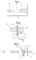
Figure 1 is a schematic view showing a projection unit comprising a laser speckle suppression device according to the invention. -
Figure 2 is a schematic view showing a first embodiment of the laser speckle suppression device offigure 1 . -
Figure 3 is a schematic view showing how the laser speckle suppression device offigure 2 is working. -
Figure 4 is a schematic view of a second embodiment of the laser speckle suppression device offigure 1 . -
Figure 5 is a cross section view showing the second embodiment of the laser speckle suppression device. -
Figure 6 shows the electrical configuration of the second embodiment of the laser speckle suppression device. -
Figure 7 shows a projection unit incorporated in a diffractive head up display and using the speckle suppression device according tofigure 2 . - The speckle suppression device presented in the invention is based on moving directly a diffusing medium according to a composite vibration mode. This composite vibration mode (for example bending+ rotation or + shearing) associated with the structural features of the diffuser will enable to generate for each position of the diffuser a corresponding wavefront and thus a special speckle noise. The averaging of these wavefronts will enable a real random spatial phase averaging, which can reduce the speckle, whatever its magnitude, and at the same time to correct the uniformity of the beam.
- As can be seen on
figure 1 , theprojection unit 10 is constituted of alaser type source 12 generating a coherent light beam, a beam shaping element 14 (diffractive or not) and adisplay 16. A laserspeckle suppression device 18 is positioned between thelaser source 12 and thedisplay 16. - In a first embodiment of the laser
speckle suppression device 18, as shown onfigure 2 , the laserspeckle suppression device 18 is constituted of a vibratingmetallic structure 20 on which an opticaldiffusing element 22 is fixed through which thelaser beam 24 passes.Piezoelectric plates 26 are fixed on the vibratingstructure 20. An electronic oscillatingcircuit 28 is designed to drive the vibrations in the piezoelectric elements at the desired frequency and at the desired vibration mode. This method enables to apply directly a vibrating movement to the diffusingelement 22. - In a second embodiment of the laser
speckle suppression device 18, as shown onfigures 4 to 6 , the laserspeckle suppression device 18 is constituted of aquartz plate 30 on which adiffusion layer 32 is deposited.Electrodes 34 are directly deposited on the quartz plate surfaces. Theseelectrodes 34 are used in order to generate the required vibrating modes at the required frequency. The quartz plate is fixed for example on asupport surface 36 on the electronic PCB including thedriving electronics 28. This embodiment uses directly the piezoelectric properties of the quartz in order to generate the required vibrating modes at the desired frequency, and enables a simple integration with the associateddriving electronics 28. Also the optical characteristics of the quartz plate 30 (transparent material with a refraction index about 1.458) enable to use it directly for both functions: optical function and piezoelectric function. Also in this version the speckle is reduced due to the random averaging of the phase, and also the uniformization of the beam is obtained. - For both embodiments of the laser
speckle suppression device 18, theelectronic circuit 28 is designed in order to assure the vibration of the structure at the required vibration frequency. In fact, this frequency is related to the chosen vibrating mode. - As explained above the vibration of the diffusing
element 22 randomly averages the image and thus reduces the speckle by virtually creating a mean value of the laser wavelength. Generally it is enough to drive the vibration at a frequency higher than that of the human eye sensitivity with sufficient amplitude. The random vibrations at that frequency will enable the eye to see a mean value of the images superposed on thediffusing element 22. As the piezoelectric actuating according to the present invention is specifically designed to generate the composite vibration mode at the desired frequency and amplitude, the frequency is chosen with respect to the eye sensitivity criterion and to comfort requirements (no audible noise is generated by the device). - This kind of
projection systems 10 having suchspeckle suppression device 18 can be suitable for application such as head up displays based on diffractive (or holographic) combiners. In such kind of head up displays, it is necessary to reduce the speckle effect in order to improve the quality of the virtual image. In fact the speckle effect is generally magnified by the diffractive combiner. - According to the present invention, the
projection unit 10 for the diffractive head updisplay 42 presented onfigure 7 , comprises alaser source 12, a diffractivebeam shaping element 14, twomirrors display 16. The diffractivebeam shaping element 14 is designed to obtain a light spot having the same shape and dimensions as thedisplay 16 with a high uniformity and a high energetic efficiency. The laserspeckle suppression device 18 shown corresponds to the first embodiment of the invention. The laserspeckle suppression device 18 can be easily integrated within theprojection unit 10 and within the head updisplay 42 without any need to modify the optical design initially defined.
Claims (8)
- A projection unit (10) comprising a coherent light source (12) such as a laser diode and a beam shaping element (14) forming a light beam (24) which is directed towards a display (16), characterized in that it comprises a laser speckle suppression device (18) which is positioned between the light source (12) and the display (16) and wherein the laser speckle suppression device (18) is a diffusing element (22) actuated randomly by a vibrating structure.
- The projection unit (10) according to claim 1, characterized in that the vibrating structure is arranged with regards to the diffusing element (22) so as to generate a composite vibration movement including displacement of the diffusing element (22) along an axis substantially parallel to the light beam (24) direction in order to generate different wave fronts with different speckle characteristics on the display (16).
- The projection unit (10) according to claim 2, characterized in that the composite vibration movement includes a pivoting movement of the diffusing element (22) along an axis substantially orthogonal to the light beam direction.
- The projection unit (10) according to anyone of the preceding claims, characterized in that the laser speckle suppression device (18) includes a metallic structure (20) with piezoelectric elements (26) forming the vibrating structure, the diffusing element (22) being mounted on the metallic structure (20) to be actuated.
- The projection unit (10) according to anyone of claims 1 to 3, characterized in that the laser speckle suppression device (18) includes a quartz plate (30) forming the diffusing element (22) and in that the diffusing element (22) is actuated by electrodes (34) deposited on opposite sides of the quartz plate (30).
- The projection unit (10) according to the preceding claim, characterized in that the quartz plate (30) includes a diffusion layer (32).
- The projection unit (10) according to anyone of the preceding claims, characterized in that the vibrating structure is mounted on a printed circuit board, and in that the printed circuit board comprises an electronic control unit to control the laser speckle suppression device (18).
- A head-up display (42) characterized in that it comprises a projection unit (10) according to anyone of the preceding claims.
Priority Applications (2)
| Application Number | Priority Date | Filing Date | Title |
|---|---|---|---|
| EP09154420.5A EP2196844B1 (en) | 2008-12-10 | 2009-03-05 | A projection unit having a speckle suppression device based on piezoelectric actuating |
| US12/630,066 US8500287B2 (en) | 2008-12-10 | 2009-12-03 | Projection unit having speckle suppression device based on piezoelectric actuating |
Applications Claiming Priority (2)
| Application Number | Priority Date | Filing Date | Title |
|---|---|---|---|
| EP08171221 | 2008-12-10 | ||
| EP09154420.5A EP2196844B1 (en) | 2008-12-10 | 2009-03-05 | A projection unit having a speckle suppression device based on piezoelectric actuating |
Publications (2)
| Publication Number | Publication Date |
|---|---|
| EP2196844A1 true EP2196844A1 (en) | 2010-06-16 |
| EP2196844B1 EP2196844B1 (en) | 2014-09-10 |
Family
ID=41417467
Family Applications (1)
| Application Number | Title | Priority Date | Filing Date |
|---|---|---|---|
| EP09154420.5A Active EP2196844B1 (en) | 2008-12-10 | 2009-03-05 | A projection unit having a speckle suppression device based on piezoelectric actuating |
Country Status (2)
| Country | Link |
|---|---|
| US (1) | US8500287B2 (en) |
| EP (1) | EP2196844B1 (en) |
Cited By (6)
| Publication number | Priority date | Publication date | Assignee | Title |
|---|---|---|---|---|
| WO2010134980A3 (en) * | 2009-05-21 | 2011-03-03 | Eastman Kodak Company | Optical laser projection system with speckle reduction element configured for out-of-plane motion |
| US8172404B2 (en) | 2009-05-21 | 2012-05-08 | Eastman Kodak Company | Projection with lenslet arrangement on speckle reduction element |
| US8172403B2 (en) | 2009-05-21 | 2012-05-08 | Eastman Kodak Company | Projection with curved speckle reduction element surface |
| CN110308026A (en) * | 2019-06-11 | 2019-10-08 | 江西昌河航空工业有限公司 | A kind of surface treatment method of pair of composite material blade iron clad detection |
| WO2021013520A1 (en) * | 2019-07-23 | 2021-01-28 | Signify Holding B.V. | Laser based white light source with adjustable sparkling |
| WO2023247825A1 (en) * | 2022-06-22 | 2023-12-28 | Modulight Corporation | Optical assembly and optical system |
Families Citing this family (12)
| Publication number | Priority date | Publication date | Assignee | Title |
|---|---|---|---|---|
| WO2007144816A2 (en) * | 2006-06-12 | 2007-12-21 | Koninklijke Philips Electronics N.V. | A method and a lighting system |
| US8437059B2 (en) * | 2010-01-21 | 2013-05-07 | Technion Research & Development Foundation Limited | Method for reconstructing a holographic projection |
| FR2959574B1 (en) * | 2010-04-28 | 2012-08-17 | Delphi Tech Inc | SPECKLE REDUCER AND PROJECTION UNIT COMPRISING A SPECKLE REDUCER |
| CN102486576B (en) * | 2010-12-02 | 2013-08-14 | 杭州中科新松光电有限公司 | Speckle elimination apparatus for vibrating laser display and elimination method thereof |
| JP5848504B2 (en) * | 2011-02-24 | 2016-01-27 | スタンレー電気株式会社 | Optical deflector |
| TW201400918A (en) * | 2012-03-27 | 2014-01-01 | Touch Micro System Tech | Phase modulation module and projector comprising the same |
| DE102013008372A1 (en) | 2013-05-16 | 2014-11-20 | GM Global Technology Operations LLC (n. d. Gesetzen des Staates Delaware) | Method and device for reducing speckles of an image of an object generated in a reproduction device |
| TWI502223B (en) * | 2014-01-03 | 2015-10-01 | Univ Nat Taiwan | Partial random laser illumination system and device having random phase and amplitude component |
| DE102014118378A1 (en) * | 2014-12-11 | 2016-06-16 | Hella Kgaa Hueck & Co. | Lighting device for vehicles |
| US9958700B2 (en) | 2015-07-30 | 2018-05-01 | Eastman Kodak Company | Optical modulator for laser speckle reduction |
| US11194170B2 (en) | 2017-09-01 | 2021-12-07 | Wayray Ag | Torsion spring speckle diffuser |
| CN113465538A (en) * | 2021-07-01 | 2021-10-01 | 北京的卢深视科技有限公司 | Speckle projection device, manufacturing method of speckle projection device and electronic equipment |
Citations (11)
| Publication number | Priority date | Publication date | Assignee | Title |
|---|---|---|---|---|
| US4155630A (en) | 1977-11-17 | 1979-05-22 | University Of Delaware | Speckle elimination by random spatial phase modulation |
| WO2000065401A1 (en) | 1999-04-28 | 2000-11-02 | Intel Corporation | Mechanically oscillated projection display |
| EP1328128A1 (en) | 2002-01-15 | 2003-07-16 | EASTMAN KODAK COMPANY (a New Jersey corporation) | Laser projection display system |
| EP1510851A1 (en) * | 2003-08-25 | 2005-03-02 | Cadent Limited | Apparatus and method for providing high intensity non-coherent light and for speckle reduction |
| WO2005054929A2 (en) | 2003-12-02 | 2005-06-16 | Elop Electro-Optics Industries Ltd. | Vehicle display system |
| EP1655636A1 (en) | 2003-07-22 | 2006-05-10 | Matsushita Electric Industrial Co., Ltd. | Two-dimensional image forming apparatus |
| EP1257869B1 (en) | 2000-02-07 | 2006-09-20 | Silicon Light Machines | Method and apparatus for reducing laser speckle using polarization averaging |
| WO2007035905A2 (en) | 2005-09-21 | 2007-03-29 | Abu-Ageel Nayef M | Method and apparatus for reducing laser speckle |
| US20080055698A1 (en) | 2006-05-23 | 2008-03-06 | Samsung Electro-Mechanics Co., Ltd. | Optical modulator and optical modulator module for reducing laser speckle |
| JP2008134269A (en) | 2005-03-11 | 2008-06-12 | Matsushita Electric Ind Co Ltd | Image projector |
| GB2456170A (en) * | 2008-01-07 | 2009-07-08 | Light Blue Optics Ltd | Holographic image display systems |
Family Cites Families (11)
| Publication number | Priority date | Publication date | Assignee | Title |
|---|---|---|---|---|
| DE2315658C3 (en) * | 1973-03-29 | 1980-11-20 | Philips Patentverwaltung Gmbh, 2000 Hamburg | Method and device for reducing or eliminating the granulation occurring in laser beam projections |
| US6594090B2 (en) * | 2001-08-27 | 2003-07-15 | Eastman Kodak Company | Laser projection display system |
| DE602005016528D1 (en) * | 2004-02-04 | 2009-10-22 | Microvision Inc | GRID HEAD-UP DISPLAY AND CORRESPONDING SYSTEMS AND METHOD |
| KR100644644B1 (en) * | 2004-10-28 | 2006-11-10 | 삼성전자주식회사 | Illumination system eliminating laser speckle and one penal type of projection system employing the same |
| JP4612043B2 (en) * | 2005-03-16 | 2011-01-12 | パナソニック株式会社 | Image projection device |
| US20100220299A1 (en) * | 2006-05-26 | 2010-09-02 | Tetsuro Mizushima | Image display device |
| US7956941B2 (en) * | 2007-08-01 | 2011-06-07 | Texas Instruments Incorporated | Method and apparatus for reducing speckle in coherent light |
| US7777960B2 (en) * | 2007-09-10 | 2010-08-17 | Microvision, Inc. | Wide field of view head-up display system |
| JP5147849B2 (en) * | 2007-09-14 | 2013-02-20 | パナソニック株式会社 | projector |
| WO2009040822A2 (en) * | 2007-09-25 | 2009-04-02 | Explay Ltd. | Micro-projector |
| US7969644B2 (en) * | 2008-09-02 | 2011-06-28 | Elbit Systems Of America, Llc | System and method for despeckling an image illuminated by a coherent light source |
-
2009
- 2009-03-05 EP EP09154420.5A patent/EP2196844B1/en active Active
- 2009-12-03 US US12/630,066 patent/US8500287B2/en active Active
Patent Citations (11)
| Publication number | Priority date | Publication date | Assignee | Title |
|---|---|---|---|---|
| US4155630A (en) | 1977-11-17 | 1979-05-22 | University Of Delaware | Speckle elimination by random spatial phase modulation |
| WO2000065401A1 (en) | 1999-04-28 | 2000-11-02 | Intel Corporation | Mechanically oscillated projection display |
| EP1257869B1 (en) | 2000-02-07 | 2006-09-20 | Silicon Light Machines | Method and apparatus for reducing laser speckle using polarization averaging |
| EP1328128A1 (en) | 2002-01-15 | 2003-07-16 | EASTMAN KODAK COMPANY (a New Jersey corporation) | Laser projection display system |
| EP1655636A1 (en) | 2003-07-22 | 2006-05-10 | Matsushita Electric Industrial Co., Ltd. | Two-dimensional image forming apparatus |
| EP1510851A1 (en) * | 2003-08-25 | 2005-03-02 | Cadent Limited | Apparatus and method for providing high intensity non-coherent light and for speckle reduction |
| WO2005054929A2 (en) | 2003-12-02 | 2005-06-16 | Elop Electro-Optics Industries Ltd. | Vehicle display system |
| JP2008134269A (en) | 2005-03-11 | 2008-06-12 | Matsushita Electric Ind Co Ltd | Image projector |
| WO2007035905A2 (en) | 2005-09-21 | 2007-03-29 | Abu-Ageel Nayef M | Method and apparatus for reducing laser speckle |
| US20080055698A1 (en) | 2006-05-23 | 2008-03-06 | Samsung Electro-Mechanics Co., Ltd. | Optical modulator and optical modulator module for reducing laser speckle |
| GB2456170A (en) * | 2008-01-07 | 2009-07-08 | Light Blue Optics Ltd | Holographic image display systems |
Cited By (8)
| Publication number | Priority date | Publication date | Assignee | Title |
|---|---|---|---|---|
| WO2010134980A3 (en) * | 2009-05-21 | 2011-03-03 | Eastman Kodak Company | Optical laser projection system with speckle reduction element configured for out-of-plane motion |
| US8172404B2 (en) | 2009-05-21 | 2012-05-08 | Eastman Kodak Company | Projection with lenslet arrangement on speckle reduction element |
| US8172403B2 (en) | 2009-05-21 | 2012-05-08 | Eastman Kodak Company | Projection with curved speckle reduction element surface |
| US8366281B2 (en) | 2009-05-21 | 2013-02-05 | Eastman Kodak Company | Out-of-plane motion of speckle reduction element |
| CN110308026A (en) * | 2019-06-11 | 2019-10-08 | 江西昌河航空工业有限公司 | A kind of surface treatment method of pair of composite material blade iron clad detection |
| WO2021013520A1 (en) * | 2019-07-23 | 2021-01-28 | Signify Holding B.V. | Laser based white light source with adjustable sparkling |
| US11761606B2 (en) | 2019-07-23 | 2023-09-19 | Signify Holding B.V. | Laser based white light source with adjustable sparkling |
| WO2023247825A1 (en) * | 2022-06-22 | 2023-12-28 | Modulight Corporation | Optical assembly and optical system |
Also Published As
| Publication number | Publication date |
|---|---|
| EP2196844B1 (en) | 2014-09-10 |
| US8500287B2 (en) | 2013-08-06 |
| US20100141898A1 (en) | 2010-06-10 |
Similar Documents
| Publication | Publication Date | Title |
|---|---|---|
| EP2196844A1 (en) | A projection unit having a speckle suppression device based on piezoelectric actuating | |
| US7969644B2 (en) | System and method for despeckling an image illuminated by a coherent light source | |
| EP2240813B1 (en) | Oscillating mirror for image projection | |
| CN100481909C (en) | Projector, screen, projector system, and scintillation removing apparatus | |
| JP6581700B2 (en) | projector | |
| JP5427034B2 (en) | Holographic projection system using micromirrors for light modulation | |
| US20070273849A1 (en) | Projector | |
| US10401640B2 (en) | Micro-projection device with anti-speckle vibration mode | |
| US20150070659A1 (en) | Method for reducing speckles and a light source used in said method | |
| US9513600B2 (en) | Display device using computer generated hologram | |
| JP2010509617A (en) | Speckle reduction method and apparatus | |
| US8134770B2 (en) | Reducing speckle pattern in display images | |
| WO2016150095A1 (en) | Method and device for inhibiting laser speckles | |
| JP2011158543A (en) | Projector device and head-up display device | |
| JP4655968B2 (en) | Scintillation removal apparatus and projector | |
| JPH11218726A (en) | Speckle removing means and video providing device using the means | |
| JP2011158542A (en) | Projector device and head-up display device | |
| CN111812793B (en) | Diffuser assembly | |
| JP2008294108A (en) | Laser-light-source device | |
| KR100710371B1 (en) | Optical system for portable projector | |
| JP6478008B2 (en) | Image display device | |
| KR20230155006A (en) | Optical devices, retinal projection displays, and head-mounted displays | |
| JP2024505408A (en) | 3D image display system and method | |
| KR20080076540A (en) | Display apparatus of the diffractive optical modulator having focus depth dependent on the numerical aperture | |
| Reitterer et al. | Beam-clipping-induced diffraction effects in MEMS laser scanners for autostereoscopic outdoor displays |
Legal Events
| Date | Code | Title | Description |
|---|---|---|---|
| PUAI | Public reference made under article 153(3) epc to a published international application that has entered the european phase |
Free format text: ORIGINAL CODE: 0009012 |
|
| AK | Designated contracting states |
Kind code of ref document: A1 Designated state(s): AT BE BG CH CY CZ DE DK EE ES FI FR GB GR HR HU IE IS IT LI LT LU LV MC MK MT NL NO PL PT RO SE SI SK TR |
|
| AX | Request for extension of the european patent |
Extension state: AL BA RS |
|
| 17P | Request for examination filed |
Effective date: 20101216 |
|
| AKX | Designation fees paid |
Designated state(s): AT BE BG CH CY CZ DE DK EE ES FI FR GB GR HR HU IE IS IT LI LT LU LV MC MK MT NL NO PL PT RO SE SI SK TR |
|
| 17Q | First examination report despatched |
Effective date: 20120911 |
|
| GRAP | Despatch of communication of intention to grant a patent |
Free format text: ORIGINAL CODE: EPIDOSNIGR1 |
|
| INTG | Intention to grant announced |
Effective date: 20140414 |
|
| GRAS | Grant fee paid |
Free format text: ORIGINAL CODE: EPIDOSNIGR3 |
|
| GRAA | (expected) grant |
Free format text: ORIGINAL CODE: 0009210 |
|
| AK | Designated contracting states |
Kind code of ref document: B1 Designated state(s): AT BE BG CH CY CZ DE DK EE ES FI FR GB GR HR HU IE IS IT LI LT LU LV MC MK MT NL NO PL PT RO SE SI SK TR |
|
| REG | Reference to a national code |
Ref country code: GB Ref legal event code: FG4D |
|
| REG | Reference to a national code |
Ref country code: CH Ref legal event code: EP |
|
| REG | Reference to a national code |
Ref country code: IE Ref legal event code: FG4D |
|
| REG | Reference to a national code |
Ref country code: AT Ref legal event code: REF Ref document number: 686978 Country of ref document: AT Kind code of ref document: T Effective date: 20141015 |
|
| REG | Reference to a national code |
Ref country code: DE Ref legal event code: R096 Ref document number: 602009026538 Country of ref document: DE Effective date: 20141023 |
|
| PG25 | Lapsed in a contracting state [announced via postgrant information from national office to epo] |
Ref country code: FI Free format text: LAPSE BECAUSE OF FAILURE TO SUBMIT A TRANSLATION OF THE DESCRIPTION OR TO PAY THE FEE WITHIN THE PRESCRIBED TIME-LIMIT Effective date: 20140910 Ref country code: LT Free format text: LAPSE BECAUSE OF FAILURE TO SUBMIT A TRANSLATION OF THE DESCRIPTION OR TO PAY THE FEE WITHIN THE PRESCRIBED TIME-LIMIT Effective date: 20140910 Ref country code: NO Free format text: LAPSE BECAUSE OF FAILURE TO SUBMIT A TRANSLATION OF THE DESCRIPTION OR TO PAY THE FEE WITHIN THE PRESCRIBED TIME-LIMIT Effective date: 20141210 Ref country code: GR Free format text: LAPSE BECAUSE OF FAILURE TO SUBMIT A TRANSLATION OF THE DESCRIPTION OR TO PAY THE FEE WITHIN THE PRESCRIBED TIME-LIMIT Effective date: 20141211 Ref country code: ES Free format text: LAPSE BECAUSE OF FAILURE TO SUBMIT A TRANSLATION OF THE DESCRIPTION OR TO PAY THE FEE WITHIN THE PRESCRIBED TIME-LIMIT Effective date: 20140910 Ref country code: SE Free format text: LAPSE BECAUSE OF FAILURE TO SUBMIT A TRANSLATION OF THE DESCRIPTION OR TO PAY THE FEE WITHIN THE PRESCRIBED TIME-LIMIT Effective date: 20140910 |
|
| REG | Reference to a national code |
Ref country code: NL Ref legal event code: VDEP Effective date: 20140910 |
|
| REG | Reference to a national code |
Ref country code: LT Ref legal event code: MG4D |
|
| PG25 | Lapsed in a contracting state [announced via postgrant information from national office to epo] |
Ref country code: LV Free format text: LAPSE BECAUSE OF FAILURE TO SUBMIT A TRANSLATION OF THE DESCRIPTION OR TO PAY THE FEE WITHIN THE PRESCRIBED TIME-LIMIT Effective date: 20140910 Ref country code: HR Free format text: LAPSE BECAUSE OF FAILURE TO SUBMIT A TRANSLATION OF THE DESCRIPTION OR TO PAY THE FEE WITHIN THE PRESCRIBED TIME-LIMIT Effective date: 20140910 Ref country code: CY Free format text: LAPSE BECAUSE OF FAILURE TO SUBMIT A TRANSLATION OF THE DESCRIPTION OR TO PAY THE FEE WITHIN THE PRESCRIBED TIME-LIMIT Effective date: 20140910 |
|
| REG | Reference to a national code |
Ref country code: AT Ref legal event code: MK05 Ref document number: 686978 Country of ref document: AT Kind code of ref document: T Effective date: 20140910 |
|
| REG | Reference to a national code |
Ref country code: FR Ref legal event code: PLFP Year of fee payment: 7 |
|
| PG25 | Lapsed in a contracting state [announced via postgrant information from national office to epo] |
Ref country code: NL Free format text: LAPSE BECAUSE OF FAILURE TO SUBMIT A TRANSLATION OF THE DESCRIPTION OR TO PAY THE FEE WITHIN THE PRESCRIBED TIME-LIMIT Effective date: 20140910 |
|
| PG25 | Lapsed in a contracting state [announced via postgrant information from national office to epo] |
Ref country code: PT Free format text: LAPSE BECAUSE OF FAILURE TO SUBMIT A TRANSLATION OF THE DESCRIPTION OR TO PAY THE FEE WITHIN THE PRESCRIBED TIME-LIMIT Effective date: 20150112 Ref country code: IS Free format text: LAPSE BECAUSE OF FAILURE TO SUBMIT A TRANSLATION OF THE DESCRIPTION OR TO PAY THE FEE WITHIN THE PRESCRIBED TIME-LIMIT Effective date: 20150110 Ref country code: RO Free format text: LAPSE BECAUSE OF FAILURE TO SUBMIT A TRANSLATION OF THE DESCRIPTION OR TO PAY THE FEE WITHIN THE PRESCRIBED TIME-LIMIT Effective date: 20140910 Ref country code: EE Free format text: LAPSE BECAUSE OF FAILURE TO SUBMIT A TRANSLATION OF THE DESCRIPTION OR TO PAY THE FEE WITHIN THE PRESCRIBED TIME-LIMIT Effective date: 20140910 Ref country code: CZ Free format text: LAPSE BECAUSE OF FAILURE TO SUBMIT A TRANSLATION OF THE DESCRIPTION OR TO PAY THE FEE WITHIN THE PRESCRIBED TIME-LIMIT Effective date: 20140910 Ref country code: SK Free format text: LAPSE BECAUSE OF FAILURE TO SUBMIT A TRANSLATION OF THE DESCRIPTION OR TO PAY THE FEE WITHIN THE PRESCRIBED TIME-LIMIT Effective date: 20140910 |
|
| PG25 | Lapsed in a contracting state [announced via postgrant information from national office to epo] |
Ref country code: PL Free format text: LAPSE BECAUSE OF FAILURE TO SUBMIT A TRANSLATION OF THE DESCRIPTION OR TO PAY THE FEE WITHIN THE PRESCRIBED TIME-LIMIT Effective date: 20140910 Ref country code: AT Free format text: LAPSE BECAUSE OF FAILURE TO SUBMIT A TRANSLATION OF THE DESCRIPTION OR TO PAY THE FEE WITHIN THE PRESCRIBED TIME-LIMIT Effective date: 20140910 |
|
| REG | Reference to a national code |
Ref country code: DE Ref legal event code: R097 Ref document number: 602009026538 Country of ref document: DE |
|
| PLBE | No opposition filed within time limit |
Free format text: ORIGINAL CODE: 0009261 |
|
| STAA | Information on the status of an ep patent application or granted ep patent |
Free format text: STATUS: NO OPPOSITION FILED WITHIN TIME LIMIT |
|
| PG25 | Lapsed in a contracting state [announced via postgrant information from national office to epo] |
Ref country code: DK Free format text: LAPSE BECAUSE OF FAILURE TO SUBMIT A TRANSLATION OF THE DESCRIPTION OR TO PAY THE FEE WITHIN THE PRESCRIBED TIME-LIMIT Effective date: 20140910 |
|
| 26N | No opposition filed |
Effective date: 20150611 |
|
| PG25 | Lapsed in a contracting state [announced via postgrant information from national office to epo] |
Ref country code: IT Free format text: LAPSE BECAUSE OF FAILURE TO SUBMIT A TRANSLATION OF THE DESCRIPTION OR TO PAY THE FEE WITHIN THE PRESCRIBED TIME-LIMIT Effective date: 20140910 |
|
| PG25 | Lapsed in a contracting state [announced via postgrant information from national office to epo] |
Ref country code: LU Free format text: LAPSE BECAUSE OF FAILURE TO SUBMIT A TRANSLATION OF THE DESCRIPTION OR TO PAY THE FEE WITHIN THE PRESCRIBED TIME-LIMIT Effective date: 20150305 Ref country code: MC Free format text: LAPSE BECAUSE OF FAILURE TO SUBMIT A TRANSLATION OF THE DESCRIPTION OR TO PAY THE FEE WITHIN THE PRESCRIBED TIME-LIMIT Effective date: 20140910 |
|
| REG | Reference to a national code |
Ref country code: CH Ref legal event code: PL |
|
| PG25 | Lapsed in a contracting state [announced via postgrant information from national office to epo] |
Ref country code: SI Free format text: LAPSE BECAUSE OF FAILURE TO SUBMIT A TRANSLATION OF THE DESCRIPTION OR TO PAY THE FEE WITHIN THE PRESCRIBED TIME-LIMIT Effective date: 20140910 |
|
| REG | Reference to a national code |
Ref country code: IE Ref legal event code: MM4A |
|
| PG25 | Lapsed in a contracting state [announced via postgrant information from national office to epo] |
Ref country code: CH Free format text: LAPSE BECAUSE OF NON-PAYMENT OF DUE FEES Effective date: 20150331 Ref country code: LI Free format text: LAPSE BECAUSE OF NON-PAYMENT OF DUE FEES Effective date: 20150331 Ref country code: IE Free format text: LAPSE BECAUSE OF NON-PAYMENT OF DUE FEES Effective date: 20150305 |
|
| REG | Reference to a national code |
Ref country code: FR Ref legal event code: PLFP Year of fee payment: 8 |
|
| PG25 | Lapsed in a contracting state [announced via postgrant information from national office to epo] |
Ref country code: BE Free format text: LAPSE BECAUSE OF FAILURE TO SUBMIT A TRANSLATION OF THE DESCRIPTION OR TO PAY THE FEE WITHIN THE PRESCRIBED TIME-LIMIT Effective date: 20140910 |
|
| PG25 | Lapsed in a contracting state [announced via postgrant information from national office to epo] |
Ref country code: MT Free format text: LAPSE BECAUSE OF FAILURE TO SUBMIT A TRANSLATION OF THE DESCRIPTION OR TO PAY THE FEE WITHIN THE PRESCRIBED TIME-LIMIT Effective date: 20140910 |
|
| REG | Reference to a national code |
Ref country code: FR Ref legal event code: PLFP Year of fee payment: 9 |
|
| PG25 | Lapsed in a contracting state [announced via postgrant information from national office to epo] |
Ref country code: HU Free format text: LAPSE BECAUSE OF FAILURE TO SUBMIT A TRANSLATION OF THE DESCRIPTION OR TO PAY THE FEE WITHIN THE PRESCRIBED TIME-LIMIT; INVALID AB INITIO Effective date: 20090305 Ref country code: BG Free format text: LAPSE BECAUSE OF FAILURE TO SUBMIT A TRANSLATION OF THE DESCRIPTION OR TO PAY THE FEE WITHIN THE PRESCRIBED TIME-LIMIT Effective date: 20140910 |
|
| PG25 | Lapsed in a contracting state [announced via postgrant information from national office to epo] |
Ref country code: TR Free format text: LAPSE BECAUSE OF FAILURE TO SUBMIT A TRANSLATION OF THE DESCRIPTION OR TO PAY THE FEE WITHIN THE PRESCRIBED TIME-LIMIT Effective date: 20140910 |
|
| REG | Reference to a national code |
Ref country code: FR Ref legal event code: PLFP Year of fee payment: 10 |
|
| PG25 | Lapsed in a contracting state [announced via postgrant information from national office to epo] |
Ref country code: MK Free format text: LAPSE BECAUSE OF FAILURE TO SUBMIT A TRANSLATION OF THE DESCRIPTION OR TO PAY THE FEE WITHIN THE PRESCRIBED TIME-LIMIT Effective date: 20140910 |
|
| REG | Reference to a national code |
Ref country code: DE Ref legal event code: R081 Ref document number: 602009026538 Country of ref document: DE Owner name: APTIV TECHNOLOGIES LIMITED, BB Free format text: FORMER OWNER: DELPHI TECHNOLOGIES, INC., TROY, MICH., US |
|
| REG | Reference to a national code |
Ref country code: GB Ref legal event code: 732E Free format text: REGISTERED BETWEEN 20190117 AND 20190123 |
|
| REG | Reference to a national code |
Ref country code: GB Ref legal event code: 732E Free format text: REGISTERED BETWEEN 20190124 AND 20190130 |
|
| PGFP | Annual fee paid to national office [announced via postgrant information from national office to epo] |
Ref country code: FR Payment date: 20230325 Year of fee payment: 15 |
|
| PGFP | Annual fee paid to national office [announced via postgrant information from national office to epo] |
Ref country code: GB Payment date: 20230316 Year of fee payment: 15 Ref country code: DE Payment date: 20230314 Year of fee payment: 15 |
|
| P01 | Opt-out of the competence of the unified patent court (upc) registered |
Effective date: 20230425 |