EP2196696A2 - Vibration absorber - Google Patents
Vibration absorber Download PDFInfo
- Publication number
- EP2196696A2 EP2196696A2 EP09178264A EP09178264A EP2196696A2 EP 2196696 A2 EP2196696 A2 EP 2196696A2 EP 09178264 A EP09178264 A EP 09178264A EP 09178264 A EP09178264 A EP 09178264A EP 2196696 A2 EP2196696 A2 EP 2196696A2
- Authority
- EP
- European Patent Office
- Prior art keywords
- valve
- valve element
- damping
- pressurized
- control pressure
- Prior art date
- Legal status (The legal status is an assumption and is not a legal conclusion. Google has not performed a legal analysis and makes no representation as to the accuracy of the status listed.)
- Withdrawn
Links
Images


Classifications
-
- F—MECHANICAL ENGINEERING; LIGHTING; HEATING; WEAPONS; BLASTING
- F16—ENGINEERING ELEMENTS AND UNITS; GENERAL MEASURES FOR PRODUCING AND MAINTAINING EFFECTIVE FUNCTIONING OF MACHINES OR INSTALLATIONS; THERMAL INSULATION IN GENERAL
- F16F—SPRINGS; SHOCK-ABSORBERS; MEANS FOR DAMPING VIBRATION
- F16F9/00—Springs, vibration-dampers, shock-absorbers, or similarly-constructed movement-dampers using a fluid or the equivalent as damping medium
- F16F9/32—Details
- F16F9/34—Special valve constructions; Shape or construction of throttling passages
- F16F9/348—Throttling passages in the form of annular discs or other plate-like elements which may or may not have a spring action, operating in opposite directions or singly, e.g. annular discs positioned on top of the valve or piston body
- F16F9/3485—Throttling passages in the form of annular discs or other plate-like elements which may or may not have a spring action, operating in opposite directions or singly, e.g. annular discs positioned on top of the valve or piston body characterised by features of supporting elements intended to guide or limit the movement of the annular discs
Definitions
- the invention relates to a vibration damper according to the preamble of patent claim 1.
- the DE 41 36 261 A1 describes a method and a device for operationally influencing a damping assembly. It is provided, inter alia, that a harder damping force characteristic is maintained, even if there is no longer any excitation for the oscillating movement. This switch-back delay to a softer damping force characteristic causes a clearly rapid decay of the oscillatory motion.
- the EP 1 538 367 B1 describes a damping valve device with a progressive damping force characteristic.
- the damping force is determined by a known disc valve, whereby a comfortable driving behavior is achieved.
- a slide arranged in series with the disc valve closes. It sets a very large damping force, which is possibly limited by an opening pressure relief valve, which is connected in parallel to the slide hydraulically.
- the JP 7-1671 91 to call which also relates to a two-stage damper valve device.
- a throttle ring is used, which is arranged in the inflow to the disc valve.
- the throttle ring is held in the open position by a return spring. If the piston rod movement exceeds a defined speed, then the throttle ring assumes a throttle position due to the effective dynamic pressure forces.
- the throttle ring is axially movable within an annular groove, wherein the front and the back of the throttle ring are exactly the same size. In the throttle ring are several throttle openings executed, so that the throttle ring is balanced under static pressure load with respect to the hydraulic pressure forces.
- the object of the present invention is to provide a Dämpfventil adopted, in which alone by the utilization of the pressure conditions in the vibration damper a foreign energy-free switch-back delay is achieved.
- the object is achieved in that the second pressurized surface on the valve element is greater than the first pressurized surface and the flow connection has at least two current paths, wherein at least one current path enables a volume flow in the outflow direction from the control pressure chamber and a current path is designed with a non-return valve device, which, starting from the control pressure chamber, assumes a closed position in the event of an incident flow.
- the closing movement of the valve element begins at a defined pressure level in the control pressure chamber and runs at least almost unthrottled.
- the opening movement is delayed, since the current path through the check valve device is blocked and thus the number of open current paths compared to the state during a closing movement of the valve element is smaller.
- the open current path acts as a choke. Consequently, a delayed opening movement can be achieved solely by the advantageous geometric design of the Dämpfventil worn, without the need for an active adjustment.
- the flow connection is carried out within the valve element.
- control pressure chamber is formed by an annular web disk.
- the annular web disk can have two concentric annular webs which radially delimit the control pressure chamber.
- a second valve element which forms a second damping valve, is arranged in the flow direction in series with the valve element.
- the use of two valve elements allows Dämpfkraftkennlinien with at least two turning points, so you can separate a comfort range of a decay range.
- the valve body for the first valve element has a first valve seat surface which delimits an annular channel to the second valve element. It achieves a radially compact design and a very large flow area on the second valve element.
- the second valve element is arranged radially outside the first pressurized surface of the first valve element and comes from a defined Abhubweg on the first valve element to the plant, wherein the effective pressurized area of the sum of the first pressurized surface on the first valve element and of a pressurized the second valve element is determined, wherein the sum of the two pressurized surface is at least as large as the second pressurized surface of the first valve element. If the second valve element exceeds the defined Abhubweg, then a larger Abhubkraft acts on the first valve element and promotes its Abhubdoch.
- the second valve element is designed as a valve ring.
- the valve ring can center on a web of the first valve element running outside the control pressure chamber.
- An annular web of the annular web disc represents a Abhubbegrenzung for the second valve element.
- a valve closing spring for the second valve element is supported on the annular web disk, which thus additionally assumes the function of a spring plate.
- first valve element is flown via a first passageway and the second valve element via a second passageway with damping medium, wherein the first and the second passageway are connected in parallel.
- the ring land disc separates the first and the second passageway in the region of the outlet openings from each other.
- valve spring for the first valve element is supported on a carrier disc, which is arranged spatially between the valve element and the annular web disk. With the support disk different levels can be provided in the region of the surface of the valve body, so that z. B. a comparatively large outlet cross section is available at a passageway.
- valve body Another measure to simplify the valve body is that the second valve element centered on the ring land and not z. B. on an annular shoulder of the valve body.
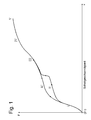
- the Fig. 1 shows a damping force / speed characteristic for a vibration damper with a Dämpfventil observed after the FIGS. 2 to 8 .
- the basic structure of a vibration damper in a motor vehicle may be regarded as known. For example, it is assumed that a damping valve device on an axially movable piston rod of the vibration damper.
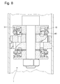
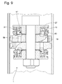
- the damper valve device 1 comprises a valve body 3, which consists of two layered valve body disks 3a; 3b is formed. In both valve body discs, a number of passage channels 5a; 5b, which guide damping medium diagonally through the valve body within a cylinder 7 of the vibration damper.
- the valve body 3 on a piston rod 9 divides the cylinder 7 into a piston rod side and a piston rod remote working space 11, 13th
- Outlet openings of the passage channels 5a; 5b lead damping medium in the direction of a first valve element 15 which is held by a valve spring 17 in a defined operating position.
- Fig. 2 can be seen that the first valve element is lifted in the defined operating position of an inner valve seat surface 19 and thus an outflow with a relatively small throttle effect from the passageway 5a; 5b is possible.
- the first valve element 15 is arranged axially movable in a control pressure chamber 21 and has two pressurized surfaces 23; 25.
- a first pressurized surface exerts at a flow from the direction of the passageways 5a; 5b, an additional opening force on the first valve element 15 from.
- To generate a closing force is the second pressurized surface 25, which is loaded by the pressure in the control pressure chamber 21.
- the second pressurized surface 25 is larger than the first pressurized surface 23 on the first valve element 15.
- a flow connection which consists of several current paths 27; 29 are formed.
- the flow connection itself is embodied within the first valve element 15.
- the flow path 27 can be flowed through in both directions, wherein this flow path is urgently to take over a Dämpfmediumablig from the control chamber in the direction of the passageways.
- a check valve device 31 is designed, which assumes a closed position in an incoming flow from the control pressure chamber 21. It may be useful to have a plurality of flow paths 29 equipped with a check valve device. As a check valve is used z.
- B. a simple ball 31 which is mounted floating between a valve closing surface 33 and a stop surface 35.
- valve spring for the first valve element is supported on a support plate 37 from.
- the carrier disk projects radially into the region of the outlet opening of the passage channels 5a; 5b, but provides a pointing in the direction of the passage channels draft for a comparatively large axial distance between the carrier disc and the outlet opening.
- the first valve element 15 slides axially in a ring land disk 39 which forms the control pressure chamber 21.
- An inner annular ridge 41 centers the annular ridge disc 39 of the piston rod 9 and biases the carrier disc 37 onto the valve body 3.
- a second valve element 43 is arranged, which forms a second damping valve.
- the second valve element rests on a second valve seat surface 45 of the valve body 3 and is biased by a valve closing spring 47.
- the valve closing spring 47 is supported on a peripheral edge outside an outer annular web 49 of the annular web disk 39.
- the outer ring land 49 represents a Abhubbegrenzung for the second valve element.
- the second valve element 43 is acted upon with pressure medium, wherein the annular channel of the first and inner valve seat surface 19 and the outer valve seat surface 45 is radially limited.
- Both the first, as well as the second valve element are as valve rings executed, wherein the second valve element centered on a running outside of the control chamber web of the first valve element.
- damping medium from the piston rod remote working space is displaced by the passage channels 5b in the direction of the first valve element 15, which is held by the valve spring 17 in an open position.
- the balls 31 of the check valve assemblies are only at a relative movement of the first valve element 15 to the annular disc 39 on one of the stop surfaces 33; 35 on.
- a closing movement of the valve element 15 the ball is located on the stop surface 35, so that all the flow paths 27; 29 are opened in the direction of the control room 21.
- the control chamber is pressurized with the pressure acting on the pressurized surface 25 causing a closing force counteracting the spring force of the valve spring 17 and the opening force caused by the pressure on the first pressurized surface 23.
- the second valve element 43 is in the starting position on the second valve seat surface 45. Between the second valve element 43 and the valve seat surface, a so-called pre-opening cross-section is then effective, which determines the damping force in the characteristic region I. As the piston rod speed increases, the excess force in the closing direction of the first valve element becomes larger, since the larger pressure-loaded surface 25 increasingly compensates for the force component of the valve spring. Like from the Fig. 3 is apparent, lifts the second valve element 43 due to the pressure level in the annular channel 51 against the closing force of the valve closing spring 47 of the second Valve seat surface 45 from. Then the Dämpfventil coupled is in a marked by the characteristic region II operating state. If the switching speed is not reached and has not been exceeded in a past time interval, a force decrease is achieved almost congruent to the characteristic II of a speed decrease.
- the characteristic region III describes the damping force characteristic of the Dämpfventil observed.
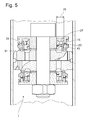
- Fig. 5 the operating behavior of the damping valve device 1 is shown in the characteristic range IV.
- the force relationships acting on the first valve element 15 change significantly.
- the surface of the second valve element 43 pressurized via the annular channel 51 now adds to the first pressurized surface 23 of the first valve element, the sum of these two surfaces being larger than the second pressurized surface 25 of the first valve element 15.
- both valve elements 15 become ; 43 moves in the opening direction.
- the check valve devices go with the ball 31 in the closed position. Over the open current path 27, a throttled entrainment movement is achieved.
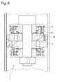
- the Fig. 6 shows the maximum passage position of the second valve element 43, wherein the first valve element 15 is lifted from the first valve seat surface 19 of the valve body 3. From this operating state, a flatter characteristic curve according to the region V in the Fig. 1 one.
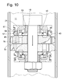
- FIG. 10 shows an alternative variant, in which the first valve element 15 is flown via a first passageway 5b and the second valve element 43 via a second passageway 5c, wherein the first and the second passageway 5b; 5c are connected in parallel.
- the two passageways 5b; 5c separated in the region of the outlet openings of the outer annular web 49 of the annular web disc 39, in which the second valve element 43 centered
- a bushing 57 is introduced on the inner wall of the outer annular web 49, which is mounted after insertion of the first valve element 15 into the control chamber 21.
Abstract
Description
Die Erfindung betrifft einen Schwingungsdämpfer gemäß dem Oberbegriff von Patentanspruch 1.The invention relates to a vibration damper according to the preamble of
Bei der Auslegung eines unverstellbaren Schwingungsdämpfers besteht grundsätzlich das Problem, einen guten Kompromiss zwischen Komfort und Fahrsicherheit zu finden. Mit der Entwicklung verstellbarer Schwingungsdämpfer ist der Widerspruch zu einem großen Teil entschärft worden, doch lässt sich auf Grund von Preisvorgaben nicht jedes Fahrzeug mit verstellbaren Schwingungsdämpfern bestücken.When designing a non-adjustable vibration damper, there is basically the problem of finding a good compromise between comfort and driving safety. With the development of adjustable vibration dampers, the contradiction has been defused to a great extent, but due to price constraints, not every vehicle can be equipped with adjustable vibration dampers.
Die
Die
In diesem Zusammenhang ist die
Fällt der dynamische Druck am Drosselring ab, dann bewegt die Rückstellfeder den Drosselring wieder in die Durchlass-Stellung.If the dynamic pressure at the throttle ring drops, then the return spring moves the throttle ring back into the passage position.
Mit den beiden Dämpfventileinrichtungen kann keine Rückschaltverzögerung wie mit der verstellbaren Dämpfungsbaugruppe erreicht werden.With the two Dämpfventileinrichtungen no switch-back delay can be achieved as with the adjustable damping assembly.
Die Aufgabe der vorliegenden Erfindung besteht darin, eine Dämpfventileinrichtung zu schaffen, bei der allein durch die Ausnutzung der Druckverhältnisse im Schwingungsdämpfer eine fremdenergiefreie Rückschaltverzögerung erreicht wird.The object of the present invention is to provide a Dämpfventileinrichtung, in which alone by the utilization of the pressure conditions in the vibration damper a foreign energy-free switch-back delay is achieved.
Erfindungsgemäß wird die Aufgabe dadurch gelöst, dass die zweite druckbeaufschlagte Fläche am Ventilelement größer ist als die erste druckbeaufschlagte Fläche und die Strömungsverbindung mindestens zwei Strompfade aufweist, wobei mindestens ein Strompfad einen Volumenstrom in Abflussrichtung aus dem Steuerdruckraum ermöglicht und ein Strompfad mit einer Rückschlagventileinrichtung ausgeführt ist, die bei einer Anströmung ausgehend vom Steuerdruckraum eine Schließstellung einnimmt.According to the invention the object is achieved in that the second pressurized surface on the valve element is greater than the first pressurized surface and the flow connection has at least two current paths, wherein at least one current path enables a volume flow in the outflow direction from the control pressure chamber and a current path is designed with a non-return valve device, which, starting from the control pressure chamber, assumes a closed position in the event of an incident flow.
Die Schließbewegung des Ventilelements setzt bei einem definierten Druckniveau im Steuerdruckraum ein und verläuft zumindest nahezu ungedrosselt. Die Öffnungsbewegung dagegen verläuft verzögert, da der Strompfad durch die Rückschlagventileinrichtung blockiert wird und damit die Anzahl der offenen Strompfade im Vergleich zum Zustand während einer Schließbewegung des Ventilelements kleiner ist. Der offene Strompfad wirkt als Drossel. Folglich kann eine verzögerte Öffnungsbewegung allein durch die vorteilhafte geometrische Ausgestaltung der Dämpfventileinrichtung erreicht werden, ohne dass es einer aktiven Verstelleinrichtung bedarf.The closing movement of the valve element begins at a defined pressure level in the control pressure chamber and runs at least almost unthrottled. The opening movement, however, is delayed, since the current path through the check valve device is blocked and thus the number of open current paths compared to the state during a closing movement of the valve element is smaller. The open current path acts as a choke. Consequently, a delayed opening movement can be achieved solely by the advantageous geometric design of the Dämpfventileinrichtung, without the need for an active adjustment.
Im Hinblick auf eine kompakte Bauform ist die Strömungsverbindung innerhalb des Ventilelements ausgeführt.With regard to a compact design, the flow connection is carried out within the valve element.
Des Weiteren ist vorgesehen, dass der Steuerdruckraum von einer Ringstegscheibe gebildet wird. Die Ringstegscheibe kann zwei konzentrische Ringstege aufweisen, die den Steuerdruckraum radial begrenzen.Furthermore, it is provided that the control pressure chamber is formed by an annular web disk. The annular web disk can have two concentric annular webs which radially delimit the control pressure chamber.
Bei einer ersten Ausführungsform ist in Strömungsrichtung in Reihe zum Ventilelement ein zweites Ventilelement angeordnet, das ein zweites Dämpfventil bildet. Die Verwendung zweier Ventilelemente ermöglicht Dämpfkraftkennlinien mit mindestens zwei Wendepunkten, so dass man einen Komfortbereich von einem Abklingbereich trennen kann.In a first embodiment, a second valve element, which forms a second damping valve, is arranged in the flow direction in series with the valve element. The use of two valve elements allows Dämpfkraftkennlinien with at least two turning points, so you can separate a comfort range of a decay range.
Der Ventilkörper für das erste Ventilelement weist eine erste Ventilsitzfläche auf, die einen Ringkanal zum zweiten Ventilelement begrenzt. Man erreicht eine radial kompakte Bauform und eine sehr große Anströmfläche am zweiten Ventilelement.The valve body for the first valve element has a first valve seat surface which delimits an annular channel to the second valve element. It achieves a radially compact design and a very large flow area on the second valve element.
In weiterer vorteilhafter Ausgestaltung ist das zweite Ventilelement radial außerhalb der ersten druckbeaufschlagten Fläche des ersten Ventilelements angeordnet ist und kommt ab einem definierten Abhubweg am ersten Ventilelement zur Anlage, wobei die wirksame druckbeaufschlagte Fläche von der Summe der ersten druckbeaufschlagten Fläche am ersten Ventilelement und von einer druckbeaufschlagten des zweiten Ventilelements bestimmt wird, wobei die Summe der beiden druckbeaufschlagten Fläche mindestens so groß ist wie die zweite druckbeaufschlagte Fläche des ersten Ventilelements. Wenn das zweite Ventilelement den definierten Abhubweg überschreitet, dann wirkt eine größere Abhubkraft auf das erste Ventilelement und fördert dessen Abhubbewegung.In a further advantageous embodiment, the second valve element is arranged radially outside the first pressurized surface of the first valve element and comes from a defined Abhubweg on the first valve element to the plant, wherein the effective pressurized area of the sum of the first pressurized surface on the first valve element and of a pressurized the second valve element is determined, wherein the sum of the two pressurized surface is at least as large as the second pressurized surface of the first valve element. If the second valve element exceeds the defined Abhubweg, then a larger Abhubkraft acts on the first valve element and promotes its Abhubbewegung.
Gemäß einem vorteilhaften Unteranspruch ist das zweite Ventilelement als ein Ventilring ausgeführt.According to an advantageous embodiment, the second valve element is designed as a valve ring.
Der Ventilring kann sich an einem außerhalb des Steuerdruckraums verlaufenden Stegs des ersten Ventilelements zentrieren.The valve ring can center on a web of the first valve element running outside the control pressure chamber.
Ein Ringsteg der Ringstegscheibe stellt eine Abhubbegrenzung für das zweite Ventilelement dar.An annular web of the annular web disc represents a Abhubbegrenzung for the second valve element.
Eine Ventilschließfeder für das zweite Ventilelement stützt sich an der Ringstegscheibe ab, die damit zusätzlich die Funktion eines Federtellers übernimmt.A valve closing spring for the second valve element is supported on the annular web disk, which thus additionally assumes the function of a spring plate.
Bei einer Alternativvariante wird das erste Ventilelement über einen ersten Durchtrittskanal und das zweite Ventilelement über einen zweiten Durchtrittskanal mit Dämpfmedium angeströmt, wobei der erste und der zweite Durchtrittskanal parallel geschaltet sind.In an alternative variant, the first valve element is flown via a first passageway and the second valve element via a second passageway with damping medium, wherein the first and the second passageway are connected in parallel.
Diese Lösung bietet den Vorteil, dass die beiden Ventilelemente praktisch keine gegenseitigen geometrischen Abhängigkeiten aufweisen, die bei der Auslegung oder Anpassung an eine gewünschte Dämpfkraftkennlinie zu berücksichtigen sind.This solution offers the advantage that the two valve elements have virtually no mutual geometric dependencies, which are to be considered in the design or adaptation to a desired damping force characteristic.
Die Ringstegsscheibe trennt den ersten und den zweiten Durchtrittskanal im Bereich der Austrittsöffnungen voneinander. Der Vorteil dieser Maßnahme besteht darin, dass sich die Oberflächenkontur am Ventilkörper im Bereich der Austrittsöffnungen der Durchtrittskanäle sehr einfach gestaltet.The ring land disc separates the first and the second passageway in the region of the outlet openings from each other. The advantage of this measure is that the surface contour on the valve body in the region of the outlet openings of the passage channels is very simple.
Die Ventilfeder für das erste Ventilelement stützt sich auf einer Trägerscheibe ab, die räumlich zwischen dem Ventilelement und der Ringstegscheibe angeordnet ist. Mit der Trägerscheibe können verschiedene Ebenen im Bereich der Oberfläche des Ventilkörpers bereitgestellt werden, so dass z. B. ein vergleichsweise großer Austrittsquerschnitt an einem Durchtrittskanal zur Verfügung steht.The valve spring for the first valve element is supported on a carrier disc, which is arranged spatially between the valve element and the annular web disk. With the support disk different levels can be provided in the region of the surface of the valve body, so that z. B. a comparatively large outlet cross section is available at a passageway.
Eine weitere Maßnahme zur Vereinfachung des Ventilkörpers besteht darin, dass sich das zweite Ventilelement an der Ringstegscheibe zentriert und nicht z. B. an einer Ringschulter des Ventilkörpers. Man kann einen standardisierten Ventilkörper mit verschiedenen Ringstegscheiben kombinieren, um verschiedene Dämpfkraftkennlinien realisieren zu können.Another measure to simplify the valve body is that the second valve element centered on the ring land and not z. B. on an annular shoulder of the valve body. One can have a standardized valve body with different ones Combine ring gear discs to realize different damping force characteristics.
Anhand der folgenden Figurenbeschreibung soll die Erfindung näher erläutert werden.The invention will be explained in more detail with reference to the following description of the figures.
Es zeigt:
- Fig. 1
- Dämpfkraftkennlinie für eine Dämpfventileinrichtung gemäß der
Fig. 2 bis 7 - Fig. 2 - 9
- Dämpfventileinrichtung mit zwei Dämpfventilen in Reihenschaltung
- Fig. 10
- Dämpfventileinrichtung mit zwei Dämpfventilen in Parallelschaltung
- Fig. 1
- Dämpfkraftkennlinie for a Dämpfventileinrichtung according to the
Fig. 2 to 7 - Fig. 2-9
- Damping valve device with two damping valves in series connection
- Fig. 10
- Damping valve device with two damping valves in parallel connection
Die
Die Dämpfventileinrichtung 1 umfasst einen Ventilkörper 3, der von zwei geschichteten Ventilkörperscheiben 3a; 3b gebildet wird. In beiden Ventilkörperscheiben ist eine Anzahl von Durchtrittskanälen 5a; 5b ausgeführt, die Dämpfmedium innerhalb eines Zylinders 7 des Schwingungsdämpfers diagonal durch den Ventilkörper leiten. Der Ventilkörper 3 an einer Kolbenstange 9 unterteilt den Zylinder 7 in einen kolbenstangenseitigen und einen kolbenstangenfernen Arbeitsraum 11, 13.The
Austrittsöffnungen der Durchtrittskanäle 5a; 5b führen Dämpfmedium in Richtung eines ersten Ventilelements 15, das von einer Ventilfeder 17 in einer definierten Betriebsstellung gehalten wird. In
Das erste Ventilelement 15 ist in einem Steuerdruckraum 21 axial beweglich angeordnet und verfügt über zwei druckbeaufschlagte Flächen 23; 25. Eine erste druckbeaufschlagte Fläche übt bei einer Anströmung aus Richtung der Durchtrittskanäle 5a; 5b eine zusätzliche Öffnungskraft auf das erste Ventilelement 15 aus. Zur Erzeugung einer Schließkraft dient die zweite druckbeaufschlagte Fläche 25, die vom Druck im Steuerdruckraum 21 belastet wird. Die zweite druckbeaufschlagte Fläche 25 ist größer als die erste druckbeaufschlagte Fläche 23 am ersten Ventilelement 15.The
Zwischen den beiden druckbeaufschlagten Flächen liegt eine Strömungsverbindung vor, die von mehreren Strompfaden 27; 29 gebildet werden. Die Strömungsverbindung selbst ist innerhalb des ersten Ventilelements 15 ausgeführt. Der Strömungspfad 27 ist sowohl in beiden Richtungen durchströmbar, wobei dieser Strömungspfad vordringlich einen Dämpfmediumabfluss aus dem Steuerraum in Richtung der Durchtrittskanäle übernehmen soll. In dem Strömungspfad 29 ist eine Rückschlagventileinrichtung 31 ausgeführt, die bei einer Anströmung ausgehend vom Steuerdruckraum 21 eine Schließstellung einnimmt. Es können sinnvollerweise mehrere Strömungspfade 29 mit einer Rückschlagventileinrichtung bestückt sein. Als Rückschlagventil dient z. B. eine einfache Kugel 31, die zwischen einer Ventilschließfläche 33 und einer Anschlagfläche 35 schwimmend gelagert ist.Between the two pressurized surfaces there is a flow connection, which consists of several
Um eine möglichst ungedrosselte Anströmung des ersten Ventilelements zu erreichen und einen einfachen Ventilkörper verwenden zu können, stützt sich die Ventilfeder für das erste Ventilelement auf einer Trägerscheibe 37 ab. Die Trägerscheibe ragt radial in den Bereich der Austrittsöffnung der Durchtrittkanäle 5a; 5b ein, doch sorgt eine in Richtung der Durchtrittskanäle weisende Formschräge für einen vergleichsweise großen axialen Abstand zwischen der Trägerscheibe und der Austrittsöffnung.In order to achieve as unthrottled flow of the first valve element and to use a simple valve body, the valve spring for the first valve element is supported on a
Das erste Ventilelement 15 gleitet axial in einer Ringstegscheibe 39, die den Steuerdruckraum 21 bildet. Ein innerer Ringsteg 41 zentriert die Ringstegscheibe 39 der Kolbenstange 9 und spannt die Trägerscheibe 37 auf den Ventilkörper 3.The
In Strömungsrichtung in Reihe zum ersten Ventilelement 15 ist ein zweites Ventilelement 43 angeordnet, das ein zweites Dämpfventil bildet. Ausgehend vom Stillstand der Kolbenstange 9 liegt das zweite Ventilelement auf einer zweiten Ventilsitzfläche 45 des Ventilkörpers 3 an und wird von einer Ventilschließfeder 47 vorgespannt. Die Ventilschließfeder 47 stützt sich an einem umlaufenden Rand außerhalb eines äußeren Ringstegs 49 der Ringstegscheibe 39 ab. Der äußere Ringsteg 49 stellt für das zweite Ventilelement eine Abhubbegrenzung dar. Über einen Ringkanal 51 wird das zweite Ventilelement 43 mit Druckmedium beaufschlagt, wobei der Ringkanal von der ersten bzw. inneren Ventilsitzfläche 19 und der äußeren Ventilsitzfläche 45 radial begrenzt wird. Sowohl das erste, wie auch das zweite Ventilelement sind als Ventilringe ausgeführt, wobei sich das zweite Ventilelement einem außerhalb des Steuerraums verlaufenden Steg des ersten Ventilelements zentriert.In the flow direction in series with the
Bei einer Kolbenstangenbewegung in Pfeilrichtung wird Dämpfmedium aus dem kolbenstangenfernen Arbeitsraum durch die Durchtrittskanäle 5b in Richtung des ersten Ventilelements 15 verdrängt, das von der Ventilfeder 17 in einer Öffnungsposition gehalten wird. Die Kugeln 31 der Rückschlagventilanordnungen liegen dabei erst bei einer Relativbewegung des ersten Ventilelements 15 zur Ringscheibe 39 an einer der Anschlagflächen 33; 35 an. Bei einer Schließbewegung des Ventilelements 15 befindet sich die Kugel an der Anschlagfläche 35, so dass sämtliche Strömungspfade 27; 29 in Richtung des Steuerraums 21 geöffnet sind. Der Steuerraum wird unter Druck gesetzt, wobei der auf die druckbeaufschlagte Fläche 25 wirksame Druck eine Schließkraft bewirkt, die der Federkraft der Ventilfeder 17 und der Öffnungskraft, hervorgerufen durch den Druck auf die erste druckbeaufschlagte Fläche 23 entgegenwirkt.In a piston rod movement in the arrow direction damping medium from the piston rod remote working space is displaced by the
Das zweite Ventilelement 43 liegt in der Ausgangsstellung auf der zweiten Ventilsitzfläche 45 auf. Zwischen zweiten Ventilelement 43 und der Ventilsitzfläche ist dann ein so genannter Voröffnungsquerschnitt wirksam, der die Dämpfkraft im Kennlinienbereich I bestimmt. Mit steigender Kolbenstangengeschwindigkeit wird der Kraftüberschuss in Schließrichtung des ersten Ventilelements größer, da die größere druckbeaufschlagte Fläche 25 den Kraftanteil der Ventilfeder zunehmend kompensiert. Wie aus der
Wird allerdings eine definierte Schallgeschwindigkeit überschritten, ist der Druckkraftüberschuss auf die zweite druckbeaufschlagte Fläche 25 des ersten Ventilelements so groß, dass das erste Ventilelement 15 auf der inneren Ventilfläche 19 aufsitzt. Dann ist über Aussparungen innerhalb der Ventilsitzfläche 19 oder im Ventilelement 15 ein Restquerschnitt 53 geöffnet. Dieser Restquerschnitt erzeugt ein Druckgefälle zwischen der Austrittsöffnung der Durchtrittskanäle 5b und dem Ringkanal 51, so dass zur weiteren Öffnungsbewegung des zweiten Ventilelements 43 eine größere Kolbenstangengeschwindigkeit v bzw. Druck im Arbeitsraum 13 notwendig ist.However, if a defined speed of sound is exceeded, the excess pressure on the second
Zwischen dem zweiten Ventilelement 43 und dem ersten Ventilelement 15 besteht noch kein axialer Kontakt, wie in der
Mit der
Die
Verringert sich die Kolbenstangengeschwindigkeit, dann nimmt die Öffnungskraft auf die beiden Ventilelemente 43; 15 ab, die eine Schließbewegung gemäß der
Im Gegensatz zur
Die
In der Ringstegscheibe ist ausgehend von der Ventilsitzfläche 19 ein Abflusskanal 55, der eine Abströmverbindung zwischen dem ersten Durchtrittskanal 5b und dem kolbenstangenseitigen Arbeitsraum 11 bildet. Der Staudruckraum 21 bleibt jedoch in allen Betriebsstellungen des ersten Ventilelements vom Abflusskanal 55 getrennt.Starting from the
Um einen Größenunterschied zwischen den beiden druckbeaufschlagten Flächen 23; 25 am ersten Ventilelement zu realisieren, ist an der Innenwand des äußeren Ringstegs 49 eine Buchse 57 eingebracht, die nach dem Einsetzen des ersten Ventilelements 15 in den Steuerraum 21 montiert wird. Zur Entlüftung und zum Volumenausgleich eines Ringraums 59 zwischen der Buchse 57 und dem ersten Ventilelement 15 dient eine Radialöffnung 61.To a size difference between the two
Das Betriebsverhalten dieser Dämpfeinrichtung entspricht im Wesentlichen dem der vorbeschriebenen Bauform nach den
Die Beschreibung beschränkt sich zwar auf die Wirkungsweise der Dämpfventileinrichtung in Pfeilrichtung, doch stellt sich ein identisches Betriebsverhalten auch bei einer Kolbenstangenbewegung in Richtung des kolbenstangenfernen Arbeitsraums ein, da die Dämpfventileinrichtung hinsichtlich der Ventilelemente um eine Teilungsfuge im Ventilkörper spiegelbildlich ausgeführt ist.Although the description is limited to the operation of the Dämpfventileinrichtung in the arrow direction, but sets an identical performance even with a piston rod movement in the direction of the piston rod remote working space, since the Dämpfventileinrichtung is designed in mirror image with respect to the valve elements to a dividing joint in the valve body.
- 11
- Dämpfventileinrichtungdamping valve device
- 33
- Ventilkörpervalve body
-
5a; 5b 5c5a;
5b 5c - DurchtrittskanälePassageways
- 77
- Zylindercylinder
- 99
- Kolbenstangepiston rod
- 1111
- kolbenstangenseitiger Arbeitsraumpiston rod side working space
- 1313
- kolbenstangenferner ArbeitsraumKolbenstangenferner workspace
- 1515
- erstes Ventilelementfirst valve element
- 1717
- Ventilfedervalve spring
- 1919
- VentilsitzflächeValve seat
- 2121
- Steuerraumcontrol room
- 2323
- erste druckbeaufschlagte Flächefirst pressurized surface
- 2525
- zweite druckbeaufschlagte Flächesecond pressurized surface
- 27; 2927; 29
- Strompfadcurrent path
- 3131
- RückschlagventileinrichtungCheck valve means
- 3333
- VentilschließflächeValve closing surface
- 3535
- Anschlagflächestop surface
- 3737
- Trägerscheibecarrier disc
- 3939
- RingstegscheibeRing contour disc
- 4141
- innerer Ringsteginner ring bridge
- 4343
- zweites Ventilelementsecond valve element
- 4545
- VentilsitzflächeValve seat
- 4747
- VentilschließfederValve closing spring
- 4949
- äußerer Ringstegouter ring bridge
- 5151
- Ringkanalannular channel
- 5353
- RestquerschnittResidual cross-section
- 5555
- Abflusskanalspillway
- 5757
- BuchseRifle
- 5959
- Ringraumannulus
- 6161
- Radialöffnungradial opening
Claims (14)
dadurch gekennzeichnet,
dass die zweite druckbeaufschlagte Fläche (25) am Ventilelement (15) größer ist als die erste druckbeaufschlagte Fläche (23) und die Strömungsverbindung mindestens zwei Strompfade (27; 29) aufweist, wobei mindestens ein Strompfad einen Volumenstrom (27) in Abflussrichtung aus dem Steuerdruckraum (21) ermöglicht und ein Strompfad (29) mit einer Rückschlagventileinrichtung (31) ausgeführt ist, die bei einer Anströmung ausgehend vom Steuerdruckraum (21) eine Schließstellung einnimmt.A damping valve device (1), comprising a valve body (3) with at least one passage (5a; 5b; 5c) which forms a damping valve with a valve element (15), the valve element (15) being guided by a valve spring (17) in a control pressure chamber (5). 21) is held in a defined operating position and is transferred at an inflow from the passageway (5a, 5b) in an opening movement, wherein the valve element (15) has a first pressurized surface (23), which upon pressurization from the at least one passageway (5a 5b) has an opening force and a second pressurized surface (25) on the valve element (15) which exerts a closing force on the valve element (15) when pressurized in the control pressure space (21), the valve element (15) above a defined pressure level Closing position is moved, wherein between the passageway (5a, 5b) and the control pressure chamber (21) at least one flow connection (2 7, 29),
characterized,
in that the second pressurized surface (25) on the valve element (15) is larger than the first pressurized surface (23) and the flow connection comprises at least two current paths (27; 29), at least one current path one Volumetric flow (27) in the outflow direction from the control pressure chamber (21) allows and a current path (29) with a check valve device (31) is executed, which assumes a closed position at a flow starting from the control pressure chamber (21).
dadurch gekennzeichnet,
dass die Strömungsverbindung (27; 29) innerhalb des Ventilelements (15) ausgeführt ist.Damping valve device according to claim 1,
characterized,
in that the flow connection (27; 29) is embodied within the valve element (15).
dadurch gekennzeichnet,
dass der Steuerdruckraum (21) von einer Ringstegscheibe (39) gebildet wird.Damping valve ring according to claim 1,
characterized,
in that the control pressure space (21) is formed by a ring web disk (39).
dadurch gekennzeichnet,
dass in Strömungsrichtung in Reihe zum Ventilelement (15) ein zweites Ventilelement (43) angeordnet ist, das ein zweites Dämpfventil bildet.Damping valve according to claim 1,
characterized,
that in the flow direction in series with the valve element (15), a second valve element (43) is arranged, which forms a second damping valve.
dadurch gekennzeichnet,
dass das erste Ventilelement über einen ersten Durchtrittskanal (5b; 5c) und das zweite Ventilelement (43) über den zweiten Durchtrittskanal (5c) mit Dämpfmedium angeströmt wird, wobei der erste und der zweite Durchtrittskanal parallel (5b; 5c) geschaltet sind.Damping valve device according to claim 1,
characterized,
that the first valve element via a first passageway (5b; 5c) and the second valve element (43) via the second passageway (5c) with damping medium is flowed, wherein the first and the second passageway are connected in parallel (5b, 5c).
dadurch gekennzeichnet,
dass der Ventilkörper (3) für das erste Ventilelement (15) eine erste Ventilsitzfläche (19) aufweist, die einen Ringkanal (51) zum zweiten Ventilelement (43) begrenzt.Damping valve according to claim 4,
characterized,
in that the valve body (3) for the first valve element (15) has a first valve seat surface (19) which delimits an annular channel (51) to the second valve element (43).
dadurch gekennzeichnet,
dass das zweite Ventilelement (43) radial außerhalb der ersten druckbeaufschlagten Fläche (23) des ersten Ventilelements (15) angeordnet ist und ab einem definierten Abhubweg am ersten Ventilelement (15) zur Anlage kommt und dabei die wirksame druckbeaufschlagte Fläche von der Summe der ersten druckbeaufschlagten Fläche (23) am ersten Ventilelement (15) und von einer druckbeaufschlagten des zweiten Ventilelements (43) bestimmt wird, wobei die Summe der beiden druckbeaufschlagten Fläche mindestens so groß ist wie die zweite druckbeaufschlagte Fläche (25) des ersten Ventilelements (15).Damping valve according to claim 4,
characterized,
in that the second valve element (43) is arranged radially outside the first pressurized surface (23) of the first valve element (15) and comes into contact with the first valve element (15) starting from a defined discharge stroke and thereby the effective pressurized area of the sum of the first pressurized Surface (23) on the first valve element (15) and of a pressurized of the second valve element (43) is determined, wherein the sum of the two pressurized surface is at least as large as the second pressurized surface (25) of the first valve element (15).
dadurch gekennzeichnet,
dass das zweite Ventilelement (43) als ein Ventilring ausgeführt ist.Damping valve according to claims 4 or 5,
characterized,
that the second valve element (43) is designed as a valve ring.
dadurch gekennzeichnet,
dass sich der Ventilring (43) an einem außerhalb des Steuerdruckraums (21) verlaufenden Stegs des ersten Ventilelements (15) zentriert.Damping valve ring according to claim 8,
characterized,
in that the valve ring (43) is centered on a web of the first valve element (15) running outside the control pressure chamber (21).
dadurch gekennzeichnet,
dass ein Ringsteg (49) der Ringstegscheibe (39) eine Abhubbegrenzung für das zweite Ventilelement (43) darstellt.Damping valve ring according to claim 4,
characterized,
that an annular web (49) of the annular web plate (39) is a Abhubbegrenzung for the second valve element (43).
dadurch gekennzeichnet,
dass sich eine Ventilschließfeder (47) für das zweite Ventilelement (43) an der Ringstegscheibe (39) abstützt.Damping valve device according to claim 3,
characterized,
in that a valve closing spring (47) for the second valve element (43) is supported on the annular web disk (39).
dadurch gekennzeichnet,
dass die Ringstegsscheibe (39) den ersten und den zweiten Durchtrittskanal (5b; 5c) im Bereich der Austrittsöffnungen voneinander trennt.Damping valve device according to claim 5,
characterized,
that the annular web plate (39) the first and second passage channel (5b; 5c) from one another in the region of the outlet openings.
dadurch gekennzeichnet,
dass sich die Ventilfeder (17) für das erste Ventilelement (15) auf einer Trägerscheibe (37) abstützt, die räumlich zwischen dem Ventilkörper (15) und der Ringstegscheibe (39) angeordnet ist.Damping valve device according to claim 1,
characterized,
in that the valve spring (17) for the first valve element (15) is supported on a support disk (37) which is arranged spatially between the valve body (15) and the annular web disk (39).
dadurch gekennzeichnet,
dass sich das zweite Ventilelement (43) an der Ringstegscheibe (39) zentriert.Damping valve device according to claim 5,
characterized,
in that the second valve element (43) is centered on the annular web disk (39).
Applications Claiming Priority (1)
| Application Number | Priority Date | Filing Date | Title |
|---|---|---|---|
| DE102008054643A DE102008054643B3 (en) | 2008-12-15 | 2008-12-15 | vibration |
Publications (2)
| Publication Number | Publication Date |
|---|---|
| EP2196696A2 true EP2196696A2 (en) | 2010-06-16 |
| EP2196696A3 EP2196696A3 (en) | 2014-07-30 |
Family
ID=42035846
Family Applications (1)
| Application Number | Title | Priority Date | Filing Date |
|---|---|---|---|
| EP09178264.9A Withdrawn EP2196696A3 (en) | 2008-12-15 | 2009-12-08 | Vibration absorber |
Country Status (2)
| Country | Link |
|---|---|
| EP (1) | EP2196696A3 (en) |
| DE (1) | DE102008054643B3 (en) |
Cited By (3)
| Publication number | Priority date | Publication date | Assignee | Title |
|---|---|---|---|---|
| CN104948640A (en) * | 2014-03-28 | 2015-09-30 | Zf腓特烈斯哈芬股份公司 | Damping valve arrangement with a multistage damping force characteristic |
| CN112648322A (en) * | 2019-10-10 | 2021-04-13 | 采埃孚股份公司 | Damping valve device for vibration damper |
| CN112648322B (en) * | 2019-10-10 | 2024-04-30 | 采埃孚股份公司 | Damping valve device for vibration damper |
Citations (9)
| Publication number | Priority date | Publication date | Assignee | Title |
|---|---|---|---|---|
| FR2476782A1 (en) * | 1980-02-27 | 1981-08-28 | Rca Corp | DAMPER FOR SUSPENSION OF MOTOR VEHICLE |
| US5501307A (en) * | 1991-10-24 | 1996-03-26 | Yamaha Hatsudoki Kabushiki Kaisha | Shock absorber |
| US5655633A (en) * | 1994-05-20 | 1997-08-12 | Tokico Ltd. | Hydraulic damper of a damping force adjusting type |
| US6234462B1 (en) * | 1998-04-07 | 2001-05-22 | Mannesmann Sachs Ag | Self-pumping hydro-pneumatic spring strut with internal leveling |
| US20030106753A1 (en) * | 2001-12-12 | 2003-06-12 | Takashi Nezu | Damping force control type hydraulic shock absorber |
| US20050115786A1 (en) * | 2003-12-01 | 2005-06-02 | Zf Friedrichshafen Ag | Damping valve assembly with a progressive damping force characteristic |
| WO2006122540A2 (en) * | 2005-05-19 | 2006-11-23 | Martin Kraiss | Method and device for controlling a shock absorber |
| US20070221457A1 (en) * | 2006-03-22 | 2007-09-27 | Zf Friedrichshafen Ag | Self-pumping hydropneumatic shock absorber |
| US20080149438A1 (en) * | 2006-12-26 | 2008-06-26 | Kayaba Industry Co., Ltd. | Damping force generating mechanism for shock absorber |
Family Cites Families (2)
| Publication number | Priority date | Publication date | Assignee | Title |
|---|---|---|---|---|
| DE3901256A1 (en) * | 1988-01-29 | 1989-08-03 | Volkswagen Ag | Automatically controlled hydraulic single-tube or twin-tube telescopic shock absorber |
| JPH07167191A (en) * | 1993-12-15 | 1995-07-04 | Tokico Ltd | Hydraulic buffer device |
-
2008
- 2008-12-15 DE DE102008054643A patent/DE102008054643B3/en not_active Expired - Fee Related
-
2009
- 2009-12-08 EP EP09178264.9A patent/EP2196696A3/en not_active Withdrawn
Patent Citations (9)
| Publication number | Priority date | Publication date | Assignee | Title |
|---|---|---|---|---|
| FR2476782A1 (en) * | 1980-02-27 | 1981-08-28 | Rca Corp | DAMPER FOR SUSPENSION OF MOTOR VEHICLE |
| US5501307A (en) * | 1991-10-24 | 1996-03-26 | Yamaha Hatsudoki Kabushiki Kaisha | Shock absorber |
| US5655633A (en) * | 1994-05-20 | 1997-08-12 | Tokico Ltd. | Hydraulic damper of a damping force adjusting type |
| US6234462B1 (en) * | 1998-04-07 | 2001-05-22 | Mannesmann Sachs Ag | Self-pumping hydro-pneumatic spring strut with internal leveling |
| US20030106753A1 (en) * | 2001-12-12 | 2003-06-12 | Takashi Nezu | Damping force control type hydraulic shock absorber |
| US20050115786A1 (en) * | 2003-12-01 | 2005-06-02 | Zf Friedrichshafen Ag | Damping valve assembly with a progressive damping force characteristic |
| WO2006122540A2 (en) * | 2005-05-19 | 2006-11-23 | Martin Kraiss | Method and device for controlling a shock absorber |
| US20070221457A1 (en) * | 2006-03-22 | 2007-09-27 | Zf Friedrichshafen Ag | Self-pumping hydropneumatic shock absorber |
| US20080149438A1 (en) * | 2006-12-26 | 2008-06-26 | Kayaba Industry Co., Ltd. | Damping force generating mechanism for shock absorber |
Cited By (3)
| Publication number | Priority date | Publication date | Assignee | Title |
|---|---|---|---|---|
| CN104948640A (en) * | 2014-03-28 | 2015-09-30 | Zf腓特烈斯哈芬股份公司 | Damping valve arrangement with a multistage damping force characteristic |
| CN112648322A (en) * | 2019-10-10 | 2021-04-13 | 采埃孚股份公司 | Damping valve device for vibration damper |
| CN112648322B (en) * | 2019-10-10 | 2024-04-30 | 采埃孚股份公司 | Damping valve device for vibration damper |
Also Published As
| Publication number | Publication date |
|---|---|
| EP2196696A3 (en) | 2014-07-30 |
| DE102008054643B3 (en) | 2010-09-09 |
Similar Documents
| Publication | Publication Date | Title |
|---|---|---|
| EP2159444B1 (en) | Adjustable damping valve | |
| DE102014205410B4 (en) | Shock absorbers with controllable damping force | |
| DE3932669C2 (en) | Hydraulic shock absorber | |
| DE19652819C2 (en) | Hydraulic shock absorber with controllable damping force | |
| DE10257872B4 (en) | Hydraulic shock absorber with damping force control | |
| DE102012210459B3 (en) | Adjustable damper valve device | |
| DE19734522C2 (en) | Hydraulic shock absorber with adjustable damping force | |
| EP3212958B1 (en) | Method for operating a controllable shock absorber for motor vehicles | |
| DE19710454B4 (en) | Shock absorber with rebound valve | |
| DE4223673C2 (en) | Pressure actuated valve arrangement in the piston of a shock absorber | |
| DE19750155C2 (en) | Hydraulic shock absorber with control of the damping force | |
| DE112016004157T5 (en) | shock absorber | |
| DE102011004962A1 (en) | shock absorber | |
| DE19755994C2 (en) | Piston for a hydraulic vibration damper | |
| DE4036613A1 (en) | SHOCK ABSORBER WITH VARIABLE DAMPING FORCE SELECTED AUTOMATICALLY depending on the VIBRATION OF A VEHICLE BODY | |
| DE102012204530A1 (en) | Shock absorber with damping force control | |
| DE102012210458B3 (en) | Adjustable damping valve device for attachment at piston rod of vibration damper, has deflection profile arranged upstream to inflow aperture in flow direction and established on annular element, where aperture is aligned to flow direction | |
| DE112019000908T5 (en) | DAMPING VALVE AND SHOCK ABSORBER | |
| DE4190781C2 (en) | Hydraulic vibration damper for a motor vehicle | |
| EP2366915A2 (en) | Vibration damper with stroke-dependent damping force | |
| DE112018001280T5 (en) | shock absorber | |
| DE102020209102A1 (en) | Damping valve device with progressive damping force characteristic | |
| DE112019001510B4 (en) | Damper with floating piston bleed channel | |
| DE112009003822T5 (en) | damping device | |
| DE102021201438B3 (en) | Damping valve device with progressive damping force characteristic |
Legal Events
| Date | Code | Title | Description |
|---|---|---|---|
| PUAI | Public reference made under article 153(3) epc to a published international application that has entered the european phase |
Free format text: ORIGINAL CODE: 0009012 |
|
| AK | Designated contracting states |
Kind code of ref document: A2 Designated state(s): AT BE BG CH CY CZ DE DK EE ES FI FR GB GR HR HU IE IS IT LI LT LU LV MC MK MT NL NO PL PT RO SE SI SK SM TR |
|
| AX | Request for extension of the european patent |
Extension state: AL BA RS |
|
| PUAL | Search report despatched |
Free format text: ORIGINAL CODE: 0009013 |
|
| AK | Designated contracting states |
Kind code of ref document: A3 Designated state(s): AT BE BG CH CY CZ DE DK EE ES FI FR GB GR HR HU IE IS IT LI LT LU LV MC MK MT NL NO PL PT RO SE SI SK SM TR |
|
| AX | Request for extension of the european patent |
Extension state: AL BA RS |
|
| RIC1 | Information provided on ipc code assigned before grant |
Ipc: F16F 9/348 20060101AFI20140626BHEP |
|
| STAA | Information on the status of an ep patent application or granted ep patent |
Free format text: STATUS: THE APPLICATION IS DEEMED TO BE WITHDRAWN |
|
| 18D | Application deemed to be withdrawn |
Effective date: 20140701 |