EP2196558A1 - Thin layer formation equipment and process for formation of thin layers - Google Patents
Thin layer formation equipment and process for formation of thin layers Download PDFInfo
- Publication number
- EP2196558A1 EP2196558A1 EP06797277A EP06797277A EP2196558A1 EP 2196558 A1 EP2196558 A1 EP 2196558A1 EP 06797277 A EP06797277 A EP 06797277A EP 06797277 A EP06797277 A EP 06797277A EP 2196558 A1 EP2196558 A1 EP 2196558A1
- Authority
- EP
- European Patent Office
- Prior art keywords
- component
- alx
- chamber
- thin
- halogen
- Prior art date
- Legal status (The legal status is an assumption and is not a legal conclusion. Google has not performed a legal analysis and makes no representation as to the accuracy of the status listed.)
- Withdrawn
Links
Images

Classifications
-
- C—CHEMISTRY; METALLURGY
- C23—COATING METALLIC MATERIAL; COATING MATERIAL WITH METALLIC MATERIAL; CHEMICAL SURFACE TREATMENT; DIFFUSION TREATMENT OF METALLIC MATERIAL; COATING BY VACUUM EVAPORATION, BY SPUTTERING, BY ION IMPLANTATION OR BY CHEMICAL VAPOUR DEPOSITION, IN GENERAL; INHIBITING CORROSION OF METALLIC MATERIAL OR INCRUSTATION IN GENERAL
- C23C—COATING METALLIC MATERIAL; COATING MATERIAL WITH METALLIC MATERIAL; SURFACE TREATMENT OF METALLIC MATERIAL BY DIFFUSION INTO THE SURFACE, BY CHEMICAL CONVERSION OR SUBSTITUTION; COATING BY VACUUM EVAPORATION, BY SPUTTERING, BY ION IMPLANTATION OR BY CHEMICAL VAPOUR DEPOSITION, IN GENERAL
- C23C16/00—Chemical coating by decomposition of gaseous compounds, without leaving reaction products of surface material in the coating, i.e. chemical vapour deposition [CVD] processes
- C23C16/22—Chemical coating by decomposition of gaseous compounds, without leaving reaction products of surface material in the coating, i.e. chemical vapour deposition [CVD] processes characterised by the deposition of inorganic material, other than metallic material
- C23C16/30—Deposition of compounds, mixtures or solid solutions, e.g. borides, carbides, nitrides
- C23C16/301—AIII BV compounds, where A is Al, Ga, In or Tl and B is N, P, As, Sb or Bi
- C23C16/303—Nitrides
-
- C—CHEMISTRY; METALLURGY
- C23—COATING METALLIC MATERIAL; COATING MATERIAL WITH METALLIC MATERIAL; CHEMICAL SURFACE TREATMENT; DIFFUSION TREATMENT OF METALLIC MATERIAL; COATING BY VACUUM EVAPORATION, BY SPUTTERING, BY ION IMPLANTATION OR BY CHEMICAL VAPOUR DEPOSITION, IN GENERAL; INHIBITING CORROSION OF METALLIC MATERIAL OR INCRUSTATION IN GENERAL
- C23C—COATING METALLIC MATERIAL; COATING MATERIAL WITH METALLIC MATERIAL; SURFACE TREATMENT OF METALLIC MATERIAL BY DIFFUSION INTO THE SURFACE, BY CHEMICAL CONVERSION OR SUBSTITUTION; COATING BY VACUUM EVAPORATION, BY SPUTTERING, BY ION IMPLANTATION OR BY CHEMICAL VAPOUR DEPOSITION, IN GENERAL
- C23C16/00—Chemical coating by decomposition of gaseous compounds, without leaving reaction products of surface material in the coating, i.e. chemical vapour deposition [CVD] processes
- C23C16/44—Chemical coating by decomposition of gaseous compounds, without leaving reaction products of surface material in the coating, i.e. chemical vapour deposition [CVD] processes characterised by the method of coating
- C23C16/448—Chemical coating by decomposition of gaseous compounds, without leaving reaction products of surface material in the coating, i.e. chemical vapour deposition [CVD] processes characterised by the method of coating characterised by the method used for generating reactive gas streams, e.g. by evaporation or sublimation of precursor materials
- C23C16/4488—Chemical coating by decomposition of gaseous compounds, without leaving reaction products of surface material in the coating, i.e. chemical vapour deposition [CVD] processes characterised by the method of coating characterised by the method used for generating reactive gas streams, e.g. by evaporation or sublimation of precursor materials by in situ generation of reactive gas by chemical or electrochemical reaction
-
- C—CHEMISTRY; METALLURGY
- C30—CRYSTAL GROWTH
- C30B—SINGLE-CRYSTAL GROWTH; UNIDIRECTIONAL SOLIDIFICATION OF EUTECTIC MATERIAL OR UNIDIRECTIONAL DEMIXING OF EUTECTOID MATERIAL; REFINING BY ZONE-MELTING OF MATERIAL; PRODUCTION OF A HOMOGENEOUS POLYCRYSTALLINE MATERIAL WITH DEFINED STRUCTURE; SINGLE CRYSTALS OR HOMOGENEOUS POLYCRYSTALLINE MATERIAL WITH DEFINED STRUCTURE; AFTER-TREATMENT OF SINGLE CRYSTALS OR A HOMOGENEOUS POLYCRYSTALLINE MATERIAL WITH DEFINED STRUCTURE; APPARATUS THEREFOR
- C30B25/00—Single-crystal growth by chemical reaction of reactive gases, e.g. chemical vapour-deposition growth
- C30B25/02—Epitaxial-layer growth
-
- C—CHEMISTRY; METALLURGY
- C30—CRYSTAL GROWTH
- C30B—SINGLE-CRYSTAL GROWTH; UNIDIRECTIONAL SOLIDIFICATION OF EUTECTIC MATERIAL OR UNIDIRECTIONAL DEMIXING OF EUTECTOID MATERIAL; REFINING BY ZONE-MELTING OF MATERIAL; PRODUCTION OF A HOMOGENEOUS POLYCRYSTALLINE MATERIAL WITH DEFINED STRUCTURE; SINGLE CRYSTALS OR HOMOGENEOUS POLYCRYSTALLINE MATERIAL WITH DEFINED STRUCTURE; AFTER-TREATMENT OF SINGLE CRYSTALS OR A HOMOGENEOUS POLYCRYSTALLINE MATERIAL WITH DEFINED STRUCTURE; APPARATUS THEREFOR
- C30B29/00—Single crystals or homogeneous polycrystalline material with defined structure characterised by the material or by their shape
- C30B29/10—Inorganic compounds or compositions
- C30B29/40—AIIIBV compounds wherein A is B, Al, Ga, In or Tl and B is N, P, As, Sb or Bi
- C30B29/403—AIII-nitrides
-
- H—ELECTRICITY
- H10—SEMICONDUCTOR DEVICES; ELECTRIC SOLID-STATE DEVICES NOT OTHERWISE PROVIDED FOR
- H10P—GENERIC PROCESSES OR APPARATUS FOR THE MANUFACTURE OR TREATMENT OF DEVICES COVERED BY CLASS H10
- H10P14/00—Formation of materials, e.g. in the shape of layers or pillars
- H10P14/20—Formation of materials, e.g. in the shape of layers or pillars of semiconductor materials
- H10P14/24—Formation of materials, e.g. in the shape of layers or pillars of semiconductor materials using chemical vapour deposition [CVD]
-
- H—ELECTRICITY
- H10—SEMICONDUCTOR DEVICES; ELECTRIC SOLID-STATE DEVICES NOT OTHERWISE PROVIDED FOR
- H10P—GENERIC PROCESSES OR APPARATUS FOR THE MANUFACTURE OR TREATMENT OF DEVICES COVERED BY CLASS H10
- H10P14/00—Formation of materials, e.g. in the shape of layers or pillars
- H10P14/20—Formation of materials, e.g. in the shape of layers or pillars of semiconductor materials
- H10P14/34—Deposited materials, e.g. layers
- H10P14/3402—Deposited materials, e.g. layers characterised by the chemical composition
- H10P14/3414—Deposited materials, e.g. layers characterised by the chemical composition being group IIIA-VIA materials
- H10P14/3416—Nitrides
Definitions
- the present invention relates to a thin-film producing apparatus which can form a film of an AlN component, and to a method of producing a thin film.
- the plasma CVD apparatus is an apparatus for depositing a metal thin film or the like, by converting a gas of an organometallic complex or the like which is a material of the film and has been introduced in a chamber, into a plasma state by using a high-frequency wave that is incident from a high-frequency antenna, and by promoting a chemical reaction on the surface of a substrate by an active excited atom in the plasma.
- a plasma CVD apparatus hereinafter referred to as a new type of plasma CVD apparatus
- a film-forming method see following Patent Document 1, for instance
- an etching object member made from a metal component that forms a high-vapor-pressure halide, and is expected to form a film
- a halogen gas converted into a plasma state to etch above described etching object member by the radical of halogen, thereby generating a precursor of a halide of the metal component, and simultaneously only the metal component of the precursor deposit on the substrate.
- the above described new type of the plasma CVD apparatus is structured so as to form the metal film on the substrate by controlling the temperature of the substrate to be lower than that of the etching object member to be a source of a metal to be deposited, at a predetermined low pressure (0.1 Torr to 0.2 Torr, for instance).
- a predetermined low pressure 0.1 Torr to 0.2 Torr, for instance.
- M metal of the etching object member
- Cl 2 a halogen gas
- a thin film of M can be formed on the above described substrate by controlling the etching object member to a high temperature (300°C to 700°C, for instance), and controlling the substrate to a low temperature (approximately 200°C, for instance). This process is considered to be caused by the following reactions.
- the above described new type of the CVD apparatus appropriately keeps a ratio of MCl to Cl * to make a deposition reaction appropriately proceed.
- a flow rate of Cl 2 gas, a pressure, a power, temperatures of the substrate and the etching object member, a distance between the substrate and the etching object member, and the like as film-forming conditions are appropriately set, and thereby the ratio of MCl and Cl * can be controlled to be approximately the same, and M is detected without lowering a film-forming speed, and besides, without making Cl * excessively etch the substrate.
- AlN aluminum nitride
- MCl in the reaction formula becomes AlX 3 .
- AlX 3 is stable, so that it is difficult to cause the etching (reducing) reaction due to Cl * , under present circumstances.
- the compatibility with a raw material of nitrogen or the like is also important, and such a technology has not been established as to unfailingly produce the thin film of AlN in the new type of the CVD apparatus.
- Patent Document 1 Japanese Patent Application Laid-Open No. 2003-147534
- the present invention is designed with respect to the above described circumstances, and the object is to provide a thin-film producing apparatus and a method of producing the thin film which can unfailingly produce a thin film of AlN with the use of a new type of a CVD apparatus.
- a thin-film producing apparatus of the present invention comprises a chamber configured to accommodate a substrate therein; an etching object member containing Al configured to provide at a position opposing to the substrate in the chamber; action gas feeding means for feeding an action gas containing a halogen into the inside of the chamber; a plasma generating means for generating a plasma of the action gas by generating plasma within the chamber to generate a halogen radical, and generating a precursor AlX 3 formed by Al component contained in the etching object member and halogen X by controlling a staying period of a fluid to etch the etching object member with the halogen radical; forming means for forming NH 2 which is a compound of nitrogen and hydrogen, in the inner part of the chamber; and a controlling means for generating a intermediate product of AlX 2 from the precursor AlX 3 by lowering temperature of the substrate side less than temperature of the etching object member and simultaneously controlling the staying period of fluid, and forming AlN component generated from reaction
- the thin-film producing apparatus controls the staying period of the fluid to form the intermediate product of AlX 2 , makes the AlN component which has been produced through the reaction of NH 2 with AlX 2 form its film on the substrate side, accordingly facilitates a reduction by the halogen radical, and can unfailingly produce a thin film of AlN at low temperatures.
- a thin-film producing apparatus of the present invention comprises: a chamber configured to accommodate a substrate therein; an etching object member containing Al configured to provide at a position opposing to the substrate in the chamber; action gas feeding means for feeding an action gas containing a halogen into the inside of the chamber; a plasma generating means for generating a plasma of the action gas by generating plasma within the chamber to generate a halogen radical, and generating a precursor AlX 3 formed by Al component contained in the etching object member and halogen X by controlling a staying period of a fluid to etch the etching object member with the halogen radical; forming means for forming NH 2 which is a compound of nitrogen and hydrogen, in the inner part of the chamber; and a controlling means for generating a intermediate product of AlX from the precursor AlX 3 by lowering temperature of the substrate side less than temperature of the etching object member and simultaneously controlling the staying period of fluid, and forming AlN component generated from reaction
- the thin-film producing apparatus controls the staying period of the fluid to form the intermediate product of AlX, makes the AlN component which has been produced through the reaction of NH 2 with AlX form its film on the substrate side, accordingly facilitates a reduction by the halogen radical, and can unfailingly produce a thin film of AlN at low temperatures.
- the thin-film producing apparatus of the present invention according to claim 3 is characterized in that the forming means has a function of making ammonia (NH 3 ) react with the halogen radical to form NH 2 , in the thin-film producing apparatus according to claim 1.
- the thin-film producing apparatus can form NH 2 by using ammonia (NH 3 ).
- the thin-film producing apparatus of the present invention according to claim 4 is characterized in that the forming means has a function of converting ammonia (NH 3 ) into NH 2 and a H radical in the plasma to form NH 2 , in the thin-film producing apparatus according to claim 1.
- the thin-film producing apparatus can form NH 2 by using ammonia (NH 3 ).
- the thin-film producing apparatus of the present invention according to claim 5 is characterized in that the forming means has a function of causing a dissociation reaction between hydrogen and nitrogen thereby to form NH 2 , in the thin-film producing apparatus according to claim 1.
- the thin-film producing apparatus can form NH 2 by using hydrogen and nitrogen.
- the thin-film producing apparatus of the present invention according to claim 6 is characterized in that the forming means includes a function of adjusting an amount of NH 2 according to a state of the precursor AlX 3 , and the control means includes a function of adjusting an amount of NH 2 to a desired state to make the Al component and the A1N component intermixed on the substrate, in the thin-film producing apparatus according to claim 1.
- the thin-film producing apparatus adjusts the amount of NH 2 to the desired state, and thereby can produce the thin film in which the Al component and the AlN component are intermixed, on the substrate.
- the thin-film producing apparatus of the present invention according to claim 7 is characterized in that the function of the control means for making the Al component and the AlN component intermixed is a function of alternately stacking the Al component and the AlN component on each other, in the thin-film producing apparatus according to claim 6.
- the thin-film producing apparatus can produce the thin film in which the Al component and the AlN component are alternately stacked on each other.
- the thin-film producing apparatus of the present invention according to claim 8 is characterized in that the staying period is derived from a value calculated by dividing the volume of the chamber by a product of a flow rate of the action gas, a temperature in the atmosphere and a pressure in the chamber, and the plasma generating means and the control means control the staying period by increasing the pressure in the chamber, in the thin-film producing apparatus according to claim 1.
- the thin-film producing apparatus increases the pressure in the chamber, and thereby can form the film of the A1N component on the substrate side.
- the thin-film producing apparatus of the present invention according to claim 9 is characterized in that the halogen contained in the action gas is chlorine, in the thin-film producing apparatus according to claim 1.
- a method of producing a thin film of the present invention comprises: forming NH 2 which is a compound of nitrogen and hydrogen, while feeding an action gas containing a halogen into a chamber; etching an etching object member containing Al with a halogen radical by controlling a staying period of a fluid to form a precursor AlX 3 formed by an Al component contained in the etching object member and the halogen X; and forming an AlN component which has been produced through a reaction of NH 2 with AlX 2 on a substrate side, while producing an intermediate product of AlX 2 from the precursor AlX 3 .
- the method of producing the thin film controls the staying period of the fluid to form the intermediate product of AlX 2 , makes the AlN component which has been produced through the reaction of NH 2 with AlX 2 form its film on the substrate side, accordingly facilitates a reduction by the halogen radical, and can unfailingly produce a thin film of AlN at low temperatures.
- a method of producing a thin film of the present invention comprises: forming NH 2 which is a compound of nitrogen and hydrogen, while feeding an action gas containing a halogen into a chamber; etching an etching object member containing Al with a halogen radical by controlling a staying period of a fluid to form a precursor AlX 3 formed by an Al component contained in the etching object member and the halogen X; and forming an AlN component which has been produced through a reaction of NH 2 with AlX 2 and the halogen radical on a substrate side, while producing an intermediate product of AlX 2 from the precursor AlX 3 .
- the method of producing the thin film controls the staying period of the fluid to form the intermediate product of AlX, makes the AlN component which has been produced through the reaction of NH 2 with AlX form its film on the substrate side, accordingly facilitates a reduction by the halogen radical, and can unfailingly produce a thin film of AlN at low temperatures.
- the method of producing the thin film of the present invention according to claim 12 is characterized in that the method of producing the thin film according to claim 10 includes making ammonia (NH 3 ) react with the halogen radical to form NH 2 .
- the method of producing the thin film can produce a thin film of AlN by using ammonia (NH 3 ).
- the method of producing the thin film of the present invention according to claim 13 is characterized in that the method of producing the thin film according to claim 10 includes converting ammonia (NH 3 ) into NH 2 and a H radical in plasma to form NH 2 .
- the method of producing the thin film can produce a thin film of AlN by using ammonia (NH 3 ).
- the method of producing the thin film of the present invention according to claim 14 is characterized in that NH 2 in the method of producing the thin film according to claim 10 includes causing a dissociation reaction between hydrogen and nitrogen to form NH 2 .
- the thin film of AlN can be produced by using hydrogen and nitrogen.
- the method of producing the thin film of the present invention according to claim 15 is characterized in that the method of producing the thin film according to claim 10 includes adjusting an amount of NH 2 according to a state of the precursor AlX 3 , and producing the thin film on the substrate, in which the Al component and the AlN component are intermixed.
- the thin-film producing apparatus adjusts the amount of NH 2 to the desired state, and thereby can produce the thin film in which the Al component and the AlN component are intermixed, on the substrate.
- the method of producing the thin film of the present invention according to claim 16 is characterized in that the method of producing the thin film according to claim 15 includes producing the thin film in which the Al component and the AlN component are alternately stacked on each other, by making the Al component and the AlN component intermixed.
- the method of producing the thin film can produce the thin film in which the Al component and the AlN component are alternately stacked on each other.
- the method of producing the thin film of the present invention according to claim 17 is characterized in that the method of producing the thin film according to claim 15 includes producing the thin film in which the AlN component and the Al component are alternately stacked on each other by making the Al component and the AlN component intermixed, on the substrate on which the thin film of Al 2 O 3 has been produced.
- the method of producing the thin film can produce a thin film in which an AlN component and an Al component are stacked, on the substrate on which the thin film of Al 2 O 3 was produced, which can be a gate metal having a high dielectric constant.
- the method of producing the thin film of the present invention according to claim 18 is characterized in that the halogen contained in the action gas is chlorine, in the method of producing the thin film according to claim 10.
- a thin-film producing apparatus is a thin-film producing apparatus which can unfailingly produce a thin film of AlN at low temperatures by using a new type of a CVD apparatus.
- a method of producing a thin film according to the present invention is a method of producing a thin film, which can unfailingly produce a thin film of AlN in an environment of a low temperature by using a new type of a CVD apparatus.
- FIG. 1 illustrates a schematic side view of a thin-film producing apparatus according to one embodiment of the present invention
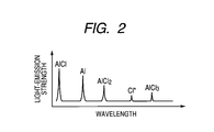
- FIG. 2 shows a graph showing a light-emitting state of plasma.
- a support table 2 is provided in the vicinity of the bottom part of a chamber 1, for instance, made from a ceramic (made from insulation material), which has been formed to be a cylindrical shape, and a substrate 3 is mounted on the support table 2.
- Temperature control means 6 which includes a heater 4 and refrigerant circulating means 5 is provided on the support table 2, and the support table 2 is controlled to a predetermined temperature (such temperature that substrate 3 is kept at 100°C to 300°C, for instance) by the temperature control means 6.
- the shape of the chamber is not limited to the cylindrical shape, but the chamber can employ, for instance, a rectangular shape as well.
- the upper face of the chamber 1 is formed to be an opening portion, and the opening portion is blocked with a tabular ceiling board 7 made from an insulation material (made from ceramic, for instance).
- a plasma antenna 8 for forming a plasma state in the inside of the chamber 1 is provided above the ceiling board 7, and the plasma antenna 8 is formed to be a planar ring shape parallel to the plane of the ceiling board 7.
- a matching box 9 and a power source 10 are connected to the plasma antenna 8, and feed a high-frequency power thereto.
- Plasma generating means for generating an induction plasma is constituted by the plasma antenna 8, the matching box 9 and the power source 10.
- An etching object member (member to be etched) 11 made from aluminum (Al) is held by the chamber 1, and is arranged in between the substrate 3 and the ceiling board 7 in a discontinuous state with respect to an electric flow of the plasma antenna 8.
- the etching object member 11 is formed, for instance, to be a grid shape and in a structurally discontinuous state with respect to the peripheral direction which is the direction of the electric flow of the plasma antenna 8.
- the etching object member which is set at a discontinuous state with respect to the electric flow of the plasma antenna 8
- One line of a gas nozzle 14 for feeding an action gas 17 containing chlorine as a halogen (gas: Cl 2 gas diluted to predetermined concentration by He) into the inner part of the chamber 1 is provided in a cylinder portion of the chamber 1 above the etching object member 11.
- the gas nozzle 14 extends to the central part of the chamber 1, and the tip is directed toward the upside and is made to be a gas blow hole 15.
- Gases of He and Cl 2 are individually controlled and sent to a flow rate controller 16, and Cl 2 action gas 17 which has been diluted by He is sent to the gas nozzle 14 through the flow rate controller 16 which controls the flow rate and the pressure (action gas feeding means).
- the shape and the arrangement of the gas nozzle 14 is not limited to the illustrated example, but for instance, a plurality of gas nozzles may be connected in the peripheral direction of the chamber 1 at equal spaces (on eight spots, for instance). Fluorine, bromine, iodine or the like can be applied to the halogen contained in the action gas. By using chlorine as the halogen, the thin film can be produced with the use of inexpensive chlorine gas.
- a nozzle 21 for feeding ammonia is provided on the cylinder portion of the chamber 1, and NH 3 is fed into the chamber 1 from the nozzle 21 through a flow rate controller 23.
- the NH 3 which has been fed into the chamber is disassociated to NH 2 and a hydrogen radical H * by plasma, and NH 2 is formed (forming means), which will be described later.
- NH 3 is converted into NH 2 and HCl through a reaction with a chlorine radical Cl * , and NH 2 is formed (forming means).
- the inside of the chamber 1 which has been sealed with the ceiling board 7 is kept at a predetermined pressure by a vacuum unit 19.
- An unshown valve of the vacuum unit 19 is controlled by control means 20, and the inside of the chamber is controlled to a desired pressure through adjustment by the valve.
- the control means 20 appropriately adjusts the output of the power source 10, and consequently can control an RF power.
- a plasma spectroscope 25 for detecting a light-emitting state of plasma (light-emission strength with respect to wavelength, for instance) is provided on the cylinder portion of the chamber 1, determines the states (spectroscopic data) of the chlorine radical Cl * , AlX 3 , AlX 2 and AlX, which will be described later, based on the spectroscopic data, and sends the spectroscopic data to the control means 20.
- the control means 20 appropriately controls the flow rate of an action gas 17 and the flow rate of NH 3 based on the sent spectroscopic data.
- the above described thin-film producing apparatus feeds the action gas 17 containing chlorine into the chamber 1, controls (prolongs) the staying period of the fluid, specifically, increases the pressure in the chamber 1, makes the chlorine radical etch the etching object member 11 containing Al to form a precursor AlCl 3 including an Al component contained in the etching object member and the halogen Cl, and simultaneously forms AlCl 2 and (or) AlCl of intermediate products.
- the thin-film producing apparatus also feeds NH 3 into the chamber 1 from the nozzle 21, and forms NH 2 by plasma or through a reaction with the chlorine radical Cl * ; and then deposits an AlN component on the substrate 3 side through a reaction of AlCl 2 (AlCl) with NH 2 (and chlorine radical Cl * ).
- the intermediate product of AlCl 2 (AlCl) is formed by prolong the staying period of the fluid, and the intermediate product is made to react with NH 2 (and chlorine radical Cl * ), and as a result, the Al component of the precursor AlX 3 is deposited on the substrate 3 side as AlN. Accordingly, a reduction by the Cl radical can be facilitated, and a thin film of AlN can be unfailingly produced.
- the staying period of the fluid is controlled by increasing the pressure in the chamber 1.
- Q represents a flow rate of gas
- T represents a temperature in the atmosphere
- P represents a pressure (760 (Torr) /P (Total))
- V represents a volume in the reaction atmosphere.
- the pressure P (Total: Torr) is set in a range of 0.1 to 0.2 (Torr), but in the present embodiment, the pressure P (Total: Torr) is set, for instance, in a range of 0.5 to 1.0 (Torr), and the staying period is set at approximately 1.5 times longer.
- the pressure P is set by the control of an unshown valve of the vacuum unit 19.
- the action gas 17 is fed to the inner part of the chamber 1, which has been controlled to 0.5 to 1.0 (Torr), from a gas nozzle 14.
- a plasma antenna 8 projects an electromagnetic wave to the inside of the chamber 1, ionizes the action gas 17 to generate a plasma of the Cl 2 gas, and forms Cl radicals.
- the plasma is generated in a region illustrated by gas plasma 12.
- the reaction at this time can be expressed by the following formula: Cl 2 ⁇ 2 ⁇ Cl * , wherein Cl * represents a chlorine radical.
- the gas plasma 12 acts on an etching object member 11 containing Al to heat the etching object member 11 and simultaneously cause an etching reaction on Al.
- the reaction at this time can be expressed, for instance, by the following formula.
- the chlorine radical Cl * acts on AlCl 3 , thereby causes the reaction of: AlCl 3 + Cl * ⁇ AlCl 2 + Cl 2 ⁇ , and forms AlCl 2 control means .
- the chlorine radical Cl * also acts on AlCl 2 , thereby causes the reaction of: AlCl 2 + Cl * ⁇ AlCl + Cl 2 ⁇ , and forms AlCl control means .
- the thin-film producing apparatus also feeds ammonia (NH 3 ) into the inside of the chamber 1 from the nozzle 21.
- NH 3 causes the reaction of: NH 3 ⁇ NH 2 ⁇ H * by gas plasma 12, that is to say, NH 3 is dissociated into NH 2 and a hydrogen radical H * , and NH 2 is formed.
- NH 3 causes the reaction of: NH 3 + Cl * ⁇ NH 2 + HCl ⁇ by the chlorine radical Cl * , that is to say, is dissociated into NH 2 and HCl, and NH 2 is formed.
- the formed NH 2 and AlCl 2 cause the reaction of: AlCl 2 + NH 2 ⁇ AlN + 2 ⁇ HCl ⁇ to deposit the AlN component on the substrate 3.
- AlCl 2 formed NH 2 , AlCl and the chlorine radical Cl * cause the reaction of: AlCl + NH 2 + Cl * ⁇ AlN + 2 ⁇ HCl ⁇ to deposit the AlN component on the substrate 3.
- the thin-film producing apparatus makes the Al component of a precursor AlX 3 react with NH 2 through easily reducible (unstable) intermediate products to form a film of AlN on a substrate 3 side, and can unfailingly produce a thin film of AlN at low temperatures.
- the thin-film producing apparatus feeds ammonia (NH 3 ) into the inside of the chamber 1 and produces the thin film of AlN, but can independently feed H 2 and N 2 and produces the thin film of AlN. In this case, it is necessary to optimally set a temperature condition or the like.
- a plasma spectroscope 25 detects a light-emitting state of plasma (light-emission strength with respect to wavelength, for instance) in the film-forming process (deposition process). Specifically, the light-emission strengths of AlCl 3 , AlCl 2 , AlCl, the chlorine radical Cl * and Al are different according to the wavelengths, as is illustrated in FIG. 2 , and accordingly the plasma spectroscope 25 can detect the states of AlCl 3 , AlCl 2 , AlCl, the chlorine radical Cl * and Al by detecting the light-emission strengths.
- the detected data by the plasma spectroscope 25 is sent to control means 20, and the control means 20 monitors whether AlCl 3 , AlCl 2 , AlCl, the chlorine radical Cl * and Al are formed in a desired state through the above described reaction process.
- the control means 20 commands a vacuum unit 19 to adjust an unshown valve and control the pressure so that AlCl 3 , AlCl 2 , AlCl, the chlorine radical Cl * and Al can be formed in the desired state.
- Such a flow rate of ammonia (NH 3 ) as to match with states of AlC1 2 and AlCl is determined on the basis of the result of monitoring, and the flow rate of ammonia (NH 3 ) is controlled by commands on the flow rate adjustment sent to a flow rate controller 23.
- the above described AlCl forms an Al component through the reaction of: AlCl + Cl * ⁇ Al + Cl 2 ⁇ , which is caused by the chlorine radical Cl * .
- the AlCl 2 forms the Al component through the reaction of: AlCl 2 + AlCl 2 ⁇ 2 ⁇ Al ⁇ + Cl 2 ⁇ , which is caused in the plasma .
- the thin-film producing apparatus repeats the feed and stop of ammonia (NH 3 ) on the basis of the detected data by the plasma spectroscope 25, thereby makes the above described reaction and a formation reaction of AlN alternately conducted, and can produce a stacked film of Al and AlN on a substrate 3.
- the chlorine radical Cl * decreases, which may cause an unequal balance with AlCl x .
- control means 20 appropriately adjusts the output of a power source 10 to increase an RF power in synchronization with an action of raising the pressure, and thereby can increase the plasma density.
- the operation increases the chlorine radical Cl * , eliminates the possibility of decreasing the chlorine radical Cl * even when having raised the pressure, and can keep the balance with AlCl x .
- a configuration of separately feeding the chlorine radical Cl * may be adopted other than a method of raising the RF power.
- the thin-film producing apparatus feeds Ar gas into the chamber 1 when having finished the film formation, generates plasma, thereby lowers an electron temperature in the vicinity of the substrate 3.
- the thin film of AlN is affected by the Cl radical Cl * which remains after the plasma has been stopped.
- the thin-film producing apparatus continuously passes He after the plasma has been stopped, makes the He react with the Cl radical Cl * , and can exhaust the resultant gas as Cl 2 gas. Thereby, the formed thin film of AlN is not affected by the remaining Cl radical Cl * .
- the present invention can provide a thin-film producing apparatus that employs a new type of a CVD apparatus and can unfailingly produce a thin film of AlN at low temperatures, and a method of producing the thin film.
- the present invention can be used in industrial fields of a thin-film producing apparatus which can form a thin film of AlN, and of a method of producing the thin film.
Landscapes
- Chemical & Material Sciences (AREA)
- General Chemical & Material Sciences (AREA)
- Engineering & Computer Science (AREA)
- Materials Engineering (AREA)
- Metallurgy (AREA)
- Organic Chemistry (AREA)
- Chemical Kinetics & Catalysis (AREA)
- Crystallography & Structural Chemistry (AREA)
- Inorganic Chemistry (AREA)
- Mechanical Engineering (AREA)
- Electrochemistry (AREA)
- Chemical Vapour Deposition (AREA)
- Formation Of Insulating Films (AREA)
Abstract
Description
- The present invention relates to a thin-film producing apparatus which can form a film of an AlN component, and to a method of producing a thin film.
- At present, in a field of manufacturing a semiconductor or the like, a film-forming method with the use of a plasma CVD (Chemical Vapor Deposition) apparatus is known. The plasma CVD apparatus is an apparatus for depositing a metal thin film or the like, by converting a gas of an organometallic complex or the like which is a material of the film and has been introduced in a chamber, into a plasma state by using a high-frequency wave that is incident from a high-frequency antenna, and by promoting a chemical reaction on the surface of a substrate by an active excited atom in the plasma.
- In contrast, the present inventors developed a plasma CVD apparatus (hereinafter referred to as a new type of plasma CVD apparatus) and a film-forming method (see following
Patent Document 1, for instance), which are followed. In the plasma CVD apparatus and the film-forming method, an etching object member made from a metal component that forms a high-vapor-pressure halide, and is expected to form a film, is provided in a chamber, a halogen gas converted into a plasma state to etch above described etching object member by the radical of halogen, thereby generating a precursor of a halide of the metal component, and simultaneously only the metal component of the precursor deposit on the substrate. - The above described new type of the plasma CVD apparatus is structured so as to form the metal film on the substrate by controlling the temperature of the substrate to be lower than that of the etching object member to be a source of a metal to be deposited, at a predetermined low pressure (0.1 Torr to 0.2 Torr, for instance). For instance, when the metal of the etching object member is represented by M, and a halogen gas is represented by Cl2, a thin film of M can be formed on the above described substrate by controlling the etching object member to a high temperature (300°C to 700°C, for instance), and controlling the substrate to a low temperature (approximately 200°C, for instance).
This process is considered to be caused by the following reactions. -
- (1) dissociation reaction of plasma; Cl2 → 2Cl*
- (2) etching reaction; M + Cl* → MCl (g)
- (3) adsorption reaction onto substrate; MCl (g) → MC1 (ad)
- (4) deposition reaction; MCl (ad) + Cl* → M + Cl2 ↑
Here, Cl* represents a radical of Cl, (g) represents a gas state, and (ad) represents an adsorbed state respectively. - The above described new type of the CVD apparatus appropriately keeps a ratio of MCl to Cl* to make a deposition reaction appropriately proceed. Specifically, a flow rate of Cl2 gas, a pressure, a power, temperatures of the substrate and the etching object member, a distance between the substrate and the etching object member, and the like as film-forming conditions are appropriately set, and thereby the ratio of MCl and Cl* can be controlled to be approximately the same, and M is detected without lowering a film-forming speed, and besides, without making Cl* excessively etch the substrate.
- It is considered to prepare a thin film of aluminum nitride (AlN) to be used for a semiconductor material or the like, by using the above described new type of the CVD apparatus. In the case of using Al for the etching object member, MCl in the reaction formula becomes AlX3. However, AlX3 is stable, so that it is difficult to cause the etching (reducing) reaction due to Cl*, under present circumstances. For this reason, the compatibility with a raw material of nitrogen or the like is also important, and such a technology has not been established as to unfailingly produce the thin film of AlN in the new type of the CVD apparatus.
- Patent Document 1: Japanese Patent Application Laid-Open No.
2003-147534 - The present invention is designed with respect to the above described circumstances, and the object is to provide a thin-film producing apparatus and a method of producing the thin film which can unfailingly produce a thin film of AlN with the use of a new type of a CVD apparatus.
- In order to achieve the above described object, a thin-film producing apparatus of the present invention according to
claim 1 comprises a chamber configured to accommodate a substrate therein; an etching object member containing Al configured to provide at a position opposing to the substrate in the chamber; action gas feeding means for feeding an action gas containing a halogen into the inside of the chamber; a plasma generating means for generating a plasma of the action gas by generating plasma within the chamber to generate a halogen radical, and generating a precursor AlX3 formed by Al component contained in the etching object member and halogen X by controlling a staying period of a fluid to etch the etching object member with the halogen radical; forming means for forming NH2 which is a compound of nitrogen and hydrogen, in the inner part of the chamber; and a controlling means for generating a intermediate product of AlX2 from the precursor AlX3 by lowering temperature of the substrate side less than temperature of the etching object member and simultaneously controlling the staying period of fluid, and forming AlN component generated from reaction of the NH2 generated by the forming means and the AlX2, on the substrate side. - Thus, the thin-film producing apparatus controls the staying period of the fluid to form the intermediate product of AlX2, makes the AlN component which has been produced through the reaction of NH2 with AlX2 form its film on the substrate side, accordingly facilitates a reduction by the halogen radical, and can unfailingly produce a thin film of AlN at low temperatures.
- In order to achieve the above described object, a thin-film producing apparatus of the present invention according to
claim 2 comprises: a chamber configured to accommodate a substrate therein; an etching object member containing Al configured to provide at a position opposing to the substrate in the chamber; action gas feeding means for feeding an action gas containing a halogen into the inside of the chamber; a plasma generating means for generating a plasma of the action gas by generating plasma within the chamber to generate a halogen radical, and generating a precursor AlX3 formed by Al component contained in the etching object member and halogen X by controlling a staying period of a fluid to etch the etching object member with the halogen radical; forming means for forming NH2 which is a compound of nitrogen and hydrogen, in the inner part of the chamber; and a controlling means for generating a intermediate product of AlX from the precursor AlX3 by lowering temperature of the substrate side less than temperature of the etching object member and simultaneously controlling the staying period of fluid, and forming AlN component generated from reaction of the NH2 generated by the forming means, the AlX, and the halogen radical, on the substrate side. - Thus, the thin-film producing apparatus controls the staying period of the fluid to form the intermediate product of AlX, makes the AlN component which has been produced through the reaction of NH2 with AlX form its film on the substrate side, accordingly facilitates a reduction by the halogen radical, and can unfailingly produce a thin film of AlN at low temperatures.
- The thin-film producing apparatus of the present invention according to
claim 3 is characterized in that the forming means has a function of making ammonia (NH3) react with the halogen radical to form NH2, in the thin-film producing apparatus according toclaim 1. - Thus, the thin-film producing apparatus can form NH2 by using ammonia (NH3).
- The thin-film producing apparatus of the present invention according to
claim 4 is characterized in that the forming means has a function of converting ammonia (NH3) into NH2 and a H radical in the plasma to form NH2, in the thin-film producing apparatus according toclaim 1. - Thus, the thin-film producing apparatus can form NH2 by using ammonia (NH3).
- The thin-film producing apparatus of the present invention according to
claim 5 is characterized in that the forming means has a function of causing a dissociation reaction between hydrogen and nitrogen thereby to form NH2, in the thin-film producing apparatus according toclaim 1. - Thus, the thin-film producing apparatus can form NH2 by using hydrogen and nitrogen.
- The thin-film producing apparatus of the present invention according to
claim 6 is characterized in that the forming means includes a function of adjusting an amount of NH2 according to a state of the precursor AlX3, and the control means includes a function of adjusting an amount of NH2 to a desired state to make the Al component and the A1N component intermixed on the substrate, in the thin-film producing apparatus according toclaim 1. - Thus, the thin-film producing apparatus adjusts the amount of NH2 to the desired state, and thereby can produce the thin film in which the Al component and the AlN component are intermixed, on the substrate.
- The thin-film producing apparatus of the present invention according to
claim 7 is characterized in that the function of the control means for making the Al component and the AlN component intermixed is a function of alternately stacking the Al component and the AlN component on each other, in the thin-film producing apparatus according toclaim 6. - Thus, the thin-film producing apparatus can produce the thin film in which the Al component and the AlN component are alternately stacked on each other.
- The thin-film producing apparatus of the present invention according to claim 8 is characterized in that the staying period is derived from a value calculated by dividing the volume of the chamber by a product of a flow rate of the action gas, a temperature in the atmosphere and a pressure in the chamber, and the plasma generating means and the control means control the staying period by increasing the pressure in the chamber, in the thin-film producing apparatus according to
claim 1. - Thus, the thin-film producing apparatus increases the pressure in the chamber, and thereby can form the film of the A1N component on the substrate side.
- The thin-film producing apparatus of the present invention according to
claim 9 is characterized in that the halogen contained in the action gas is chlorine, in the thin-film producing apparatus according toclaim 1. - Thus, inexpensive chlorine can be used.
- In order to achieve the above described object, a method of producing a thin film of the present invention according to
claim 10 comprises: forming NH2 which is a compound of nitrogen and hydrogen, while feeding an action gas containing a halogen into a chamber; etching an etching object member containing Al with a halogen radical by controlling a staying period of a fluid to form a precursor AlX3 formed by an Al component contained in the etching object member and the halogen X; and forming an AlN component which has been produced through a reaction of NH2 with AlX2 on a substrate side, while producing an intermediate product of AlX2 from the precursor AlX3. - Thus, the method of producing the thin film controls the staying period of the fluid to form the intermediate product of AlX2, makes the AlN component which has been produced through the reaction of NH2 with AlX2 form its film on the substrate side, accordingly facilitates a reduction by the halogen radical, and can unfailingly produce a thin film of AlN at low temperatures.
- In order to achieve the above described object, a method of producing a thin film of the present invention according to
claim 11 comprises: forming NH2 which is a compound of nitrogen and hydrogen, while feeding an action gas containing a halogen into a chamber; etching an etching object member containing Al with a halogen radical by controlling a staying period of a fluid to form a precursor AlX3 formed by an Al component contained in the etching object member and the halogen X; and forming an AlN component which has been produced through a reaction of NH2 with AlX2 and the halogen radical on a substrate side, while producing an intermediate product of AlX2 from the precursor AlX3. - Thus, the method of producing the thin film controls the staying period of the fluid to form the intermediate product of AlX, makes the AlN component which has been produced through the reaction of NH2 with AlX form its film on the substrate side, accordingly facilitates a reduction by the halogen radical, and can unfailingly produce a thin film of AlN at low temperatures.
- The method of producing the thin film of the present invention according to
claim 12 is characterized in that the method of producing the thin film according toclaim 10 includes making ammonia (NH3) react with the halogen radical to form NH2. - Thus, the method of producing the thin film can produce a thin film of AlN by using ammonia (NH3).
- The method of producing the thin film of the present invention according to claim 13 is characterized in that the method of producing the thin film according to
claim 10 includes converting ammonia (NH3) into NH2 and a H radical in plasma to form NH2. - Thus, the method of producing the thin film can produce a thin film of AlN by using ammonia (NH3).
- The method of producing the thin film of the present invention according to
claim 14 is characterized in that NH2 in the method of producing the thin film according toclaim 10 includes causing a dissociation reaction between hydrogen and nitrogen to form NH2. - Thus, the thin film of AlN can be produced by using hydrogen and nitrogen.
- The method of producing the thin film of the present invention according to
claim 15 is characterized in that the method of producing the thin film according toclaim 10 includes adjusting an amount of NH2 according to a state of the precursor AlX3, and producing the thin film on the substrate, in which the Al component and the AlN component are intermixed. - Thus, the thin-film producing apparatus adjusts the amount of NH2 to the desired state, and thereby can produce the thin film in which the Al component and the AlN component are intermixed, on the substrate.
- The method of producing the thin film of the present invention according to
claim 16 is characterized in that the method of producing the thin film according toclaim 15 includes producing the thin film in which the Al component and the AlN component are alternately stacked on each other, by making the Al component and the AlN component intermixed. - Thus, the method of producing the thin film can produce the thin film in which the Al component and the AlN component are alternately stacked on each other.
- The method of producing the thin film of the present invention according to
claim 17 is characterized in that the method of producing the thin film according toclaim 15 includes producing the thin film in which the AlN component and the Al component are alternately stacked on each other by making the Al component and the AlN component intermixed, on the substrate on which the thin film of Al2O3 has been produced. - Thus, the method of producing the thin film can produce a thin film in which an AlN component and an Al component are stacked, on the substrate on which the thin film of Al2O3 was produced, which can be a gate metal having a high dielectric constant.
- The method of producing the thin film of the present invention according to
claim 18 is characterized in that the halogen contained in the action gas is chlorine, in the method of producing the thin film according toclaim 10. - Thus, inexpensive chlorine can be used.
- A thin-film producing apparatus according to the present invention is a thin-film producing apparatus which can unfailingly produce a thin film of AlN at low temperatures by using a new type of a CVD apparatus. In addition, a method of producing a thin film according to the present invention is a method of producing a thin film, which can unfailingly produce a thin film of AlN in an environment of a low temperature by using a new type of a CVD apparatus.
-
-
FIG. 1 is a schematic side view of a thin-film producing apparatus according to one embodiment of the present invention; and -
FIG. 2 is a graph showing a light-emitting state of plasma. - Embodiments according to the present invention will now be described in detail below with reference to the drawings.
-
FIG. 1 illustrates a schematic side view of a thin-film producing apparatus according to one embodiment of the present invention; andFIG. 2 shows a graph showing a light-emitting state of plasma. - As is illustrated in
FIG. 1 , a support table 2 is provided in the vicinity of the bottom part of achamber 1, for instance, made from a ceramic (made from insulation material), which has been formed to be a cylindrical shape, and asubstrate 3 is mounted on the support table 2. Temperature control means 6 which includes aheater 4 andrefrigerant circulating means 5 is provided on the support table 2, and the support table 2 is controlled to a predetermined temperature (such temperature thatsubstrate 3 is kept at 100°C to 300°C, for instance) by the temperature control means 6. Incidentally, the shape of the chamber is not limited to the cylindrical shape, but the chamber can employ, for instance, a rectangular shape as well. - The upper face of the
chamber 1 is formed to be an opening portion, and the opening portion is blocked with atabular ceiling board 7 made from an insulation material (made from ceramic, for instance). A plasma antenna 8 for forming a plasma state in the inside of thechamber 1 is provided above theceiling board 7, and the plasma antenna 8 is formed to be a planar ring shape parallel to the plane of theceiling board 7. Amatching box 9 and apower source 10 are connected to the plasma antenna 8, and feed a high-frequency power thereto. Plasma generating means for generating an induction plasma is constituted by the plasma antenna 8, thematching box 9 and thepower source 10. - An etching object member (member to be etched) 11 made from aluminum (Al) is held by the
chamber 1, and is arranged in between thesubstrate 3 and theceiling board 7 in a discontinuous state with respect to an electric flow of the plasma antenna 8. Theetching object member 11 is formed, for instance, to be a grid shape and in a structurally discontinuous state with respect to the peripheral direction which is the direction of the electric flow of the plasma antenna 8. - As for a configuration of the etching object member which is set at a discontinuous state with respect to the electric flow of the plasma antenna 8, it is also possible to form the etching object member into a mesh shape, or to form a plurality of long protrusions in the inner peripheral side of the ring.
- One line of a
gas nozzle 14 for feeding anaction gas 17 containing chlorine as a halogen (gas: Cl2 gas diluted to predetermined concentration by He) into the inner part of thechamber 1 is provided in a cylinder portion of thechamber 1 above theetching object member 11. Thegas nozzle 14 extends to the central part of thechamber 1, and the tip is directed toward the upside and is made to be agas blow hole 15. Gases of He and Cl2 are individually controlled and sent to aflow rate controller 16, and Cl2 action gas 17 which has been diluted by He is sent to thegas nozzle 14 through theflow rate controller 16 which controls the flow rate and the pressure (action gas feeding means). - The shape and the arrangement of the
gas nozzle 14 is not limited to the illustrated example, but for instance, a plurality of gas nozzles may be connected in the peripheral direction of thechamber 1 at equal spaces (on eight spots, for instance). Fluorine, bromine, iodine or the like can be applied to the halogen contained in the action gas. By using chlorine as the halogen, the thin film can be produced with the use of inexpensive chlorine gas. - In addition, a
nozzle 21 for feeding ammonia (NH3) is provided on the cylinder portion of thechamber 1, and NH3 is fed into thechamber 1 from thenozzle 21 through aflow rate controller 23. The NH3 which has been fed into the chamber is disassociated to NH2 and a hydrogen radical H* by plasma, and NH2 is formed (forming means), which will be described later. Alternatively, NH3 is converted into NH2 and HCl through a reaction with a chlorine radical Cl*, and NH2 is formed (forming means). - A gas or the like, which does not participate in a film-forming process, is emitted (exhausted) from a
vent 18. The inside of thechamber 1 which has been sealed with theceiling board 7 is kept at a predetermined pressure by avacuum unit 19. An unshown valve of thevacuum unit 19 is controlled by control means 20, and the inside of the chamber is controlled to a desired pressure through adjustment by the valve. On the other hand, the control means 20 appropriately adjusts the output of thepower source 10, and consequently can control an RF power. - In addition, a
plasma spectroscope 25 for detecting a light-emitting state of plasma (light-emission strength with respect to wavelength, for instance) is provided on the cylinder portion of thechamber 1, determines the states (spectroscopic data) of the chlorine radical Cl*, AlX3, AlX2 and AlX, which will be described later, based on the spectroscopic data, and sends the spectroscopic data to the control means 20. The control means 20 appropriately controls the flow rate of anaction gas 17 and the flow rate of NH3 based on the sent spectroscopic data. - The above described thin-film producing apparatus feeds the
action gas 17 containing chlorine into thechamber 1, controls (prolongs) the staying period of the fluid, specifically, increases the pressure in thechamber 1, makes the chlorine radical etch theetching object member 11 containing Al to form a precursor AlCl3 including an Al component contained in the etching object member and the halogen Cl, and simultaneously forms AlCl2 and (or) AlCl of intermediate products. The thin-film producing apparatus also feeds NH3 into thechamber 1 from thenozzle 21, and forms NH2 by plasma or through a reaction with the chlorine radical Cl*; and then deposits an AlN component on thesubstrate 3 side through a reaction of AlCl2 (AlCl) with NH2 (and chlorine radical Cl*). - The intermediate product of AlCl2 (AlCl) is formed by prolong the staying period of the fluid, and the intermediate product is made to react with NH2 (and chlorine radical Cl*), and as a result, the Al component of the precursor AlX3 is deposited on the
substrate 3 side as AlN. Accordingly, a reduction by the Cl radical can be facilitated, and a thin film of AlN can be unfailingly produced. - Here, the staying period of the fluid is controlled by increasing the pressure in the
chamber 1. The staying period (t) of the fluid is expressed by
- Here, Q represents a flow rate of gas, T represents a temperature in the atmosphere, P represents a pressure (760 (Torr) /P (Total)), and V represents a volume in the reaction atmosphere. Accordingly, prolonging the staying period of the fluid, by which the intermediate products of AlCl2 and AlCl is formed, can be attained by any of operations of: raising the pressure P (Total: Torr) to decrease the P to a small value; reducing the flow rate; lowering the temperature; and increasing the volume. In the present embodiment, in consideration of the controllability or the like, the staying period is prolonged by raising the pressure P (Total: Torr).
- When a metal thin film is produced by using a new type of a CVD apparatus, the pressure P (Total: Torr) is set in a range of 0.1 to 0.2 (Torr), but in the present embodiment, the pressure P (Total: Torr) is set, for instance, in a range of 0.5 to 1.0 (Torr), and the staying period is set at approximately 1.5 times longer. The pressure P is set by the control of an unshown valve of the
vacuum unit 19. - The specific film-forming (deposition) state will now be described below.
- The
action gas 17 is fed to the inner part of thechamber 1, which has been controlled to 0.5 to 1.0 (Torr), from agas nozzle 14. A plasma antenna 8 projects an electromagnetic wave to the inside of thechamber 1, ionizes theaction gas 17 to generate a plasma of the Cl2 gas, and forms Cl radicals. The plasma is generated in a region illustrated bygas plasma 12. The reaction at this time can be expressed by the following formula:
, wherein Cl* represents a chlorine radical. - The
gas plasma 12 acts on anetching object member 11 containing Al to heat theetching object member 11 and simultaneously cause an etching reaction on Al. The reaction at this time can be expressed, for instance, by the following formula.
The chlorine radical Cl* acts on AlCl3, thereby causes the reaction of:
The chlorine radical Cl* also acts on AlCl2, thereby causes the reaction of:
- The thin-film producing apparatus also feeds ammonia (NH3) into the inside of the
chamber 1 from thenozzle 21.
NH3 causes the reaction of:
bygas plasma 12, that is to say, NH3 is dissociated into NH2 and a hydrogen radical H*, and NH2 is formed. - NH3 causes the reaction of:

by the chlorine radical Cl*, that is to say, is dissociated into NH2 and HCl, and NH2 is formed. - The formed NH2 and AlCl2 cause the reaction of:

to deposit the AlN component on thesubstrate 3. - In addition, AlCl2, formed NH2, AlCl and the chlorine radical Cl* cause the reaction of:

to deposit the AlN component on thesubstrate 3. - In this way, the thin-film producing apparatus makes the Al component of a precursor AlX3 react with NH2 through easily reducible (unstable) intermediate products to form a film of AlN on a
substrate 3 side, and can unfailingly produce a thin film of AlN at low temperatures. - Incidentally, in the above described embodiment, the thin-film producing apparatus feeds ammonia (NH3) into the inside of the
chamber 1 and produces the thin film of AlN, but can independently feed H2 and N2 and produces the thin film of AlN. In this case, it is necessary to optimally set a temperature condition or the like. - When the above described thin film of Al is produced, a
plasma spectroscope 25 detects a light-emitting state of plasma (light-emission strength with respect to wavelength, for instance) in the film-forming process (deposition process). Specifically, the light-emission strengths of AlCl3, AlCl2, AlCl, the chlorine radical Cl* and Al are different according to the wavelengths, as is illustrated inFIG. 2 , and accordingly theplasma spectroscope 25 can detect the states of AlCl3, AlCl2, AlCl, the chlorine radical Cl* and Al by detecting the light-emission strengths. - The detected data by the
plasma spectroscope 25 is sent to control means 20, and the control means 20 monitors whether AlCl3, AlCl2, AlCl, the chlorine radical Cl* and Al are formed in a desired state through the above described reaction process. When the desired product has not been obtained (when the state of light-emission strengths does not match with a previously memorized state) as a result of monitoring, the control means 20 commands avacuum unit 19 to adjust an unshown valve and control the pressure so that AlCl3, AlCl2, AlCl, the chlorine radical Cl* and Al can be formed in the desired state. - Such a flow rate of ammonia (NH3) as to match with states of AlC12 and AlCl is determined on the basis of the result of monitoring, and the flow rate of ammonia (NH3) is controlled by commands on the flow rate adjustment sent to a
flow rate controller 23. - The above described AlCl forms an Al component through the reaction of:

In addition, the AlCl2 forms the Al component through the reaction of:
The thin-film producing apparatus repeats the feed and stop of ammonia (NH3) on the basis of the detected data by theplasma spectroscope 25, thereby makes the above described reaction and a formation reaction of AlN alternately conducted, and can produce a stacked film of Al and AlN on asubstrate 3. - It is also possible at this time to produce a thin film in a state in which the compositions of Al and AlN are inclined on the
substrate 3, by controlling the flow rate of ammonia (NH3). Furthermore, it is also possible to produce a stacked film of Al and AlN on thesubstrate 3 on which Al2O3 has been produced beforehand. In this case, the stacked film can be used as a gate metal having a high dielectric constant. - By the way, when the pressure is raised, the chlorine radical Cl* decreases, which may cause an unequal balance with AlClx. When a plasma density is increased, the chlorine radical Cl* and AlClx increase, so that control means 20 appropriately adjusts the output of a
power source 10 to increase an RF power in synchronization with an action of raising the pressure, and thereby can increase the plasma density. The operation increases the chlorine radical Cl*, eliminates the possibility of decreasing the chlorine radical Cl* even when having raised the pressure, and can keep the balance with AlClx. - Incidentally, as for a configuration of increasing the chlorine radical Cl*, a configuration of separately feeding the chlorine radical Cl* may be adopted other than a method of raising the RF power.
- When the thin film of AlN has been produced, it is considered that the thin film is etched by the chlorine radical Cl* when the temperature of the
substrate 3 side is kept high. In order to inhibit the thin film from being etched, the thin-film producing apparatus feeds Ar gas into thechamber 1 when having finished the film formation, generates plasma, thereby lowers an electron temperature in the vicinity of thesubstrate 3. These processes allow to reduce a radiant energy of the surface of the substrate. - Furthermore, it is considered that the thin film of AlN is affected by the Cl radical Cl* which remains after the plasma has been stopped. In order to inhibit the thin film of AlN from being affected, the thin-film producing apparatus continuously passes He after the plasma has been stopped, makes the He react with the Cl radical Cl*, and can exhaust the resultant gas as Cl2 gas. Thereby, the formed thin film of AlN is not affected by the remaining Cl radical Cl*.
- Accordingly, the present invention can provide a thin-film producing apparatus that employs a new type of a CVD apparatus and can unfailingly produce a thin film of AlN at low temperatures, and a method of producing the thin film.
- The present invention can be used in industrial fields of a thin-film producing apparatus which can form a thin film of AlN, and of a method of producing the thin film.
Claims (18)
- A thin-film producing apparatus comprising:a chamber configured to accommodate a substrate therein;an etching object member containing Al configured to provide at a position opposing to the substrate in the chamber;action gas feeding means for feeding an action gas containing a halogen into the inside of the chamber;a plasma generating means for generating a plasma of the action gas by generating plasma within the chamber to generate a halogen radical, and generating a precursor AlX3 formed by Al component contained in the etching object member and halogen X by controlling a staying period of a fluid to etch the etching object member with the halogen radical;forming means for forming NH2 which is a compound of nitrogen and hydrogen, in the inner part of the chamber; anda controlling means for generating a intermediate product of AlX2 from the precursor AlX3 by lowering temperature of the substrate side less than temperature of the etching object member and simultaneously controlling the staying period of fluid, and forming AlN component generated from reaction of the NH2 generated by the forming means and the AlX2, on the substrate side.
- A thin-film producing apparatus comprising:a chamber configured to accommodate a substrate therein;an etching object member containing Al configured to provide at a position opposing to the substrate in the chamber;action gas feeding means for feeding an action gas containing a halogen into the inside of the chamber;a plasma generating means for generating a plasma of the action gas by generating plasma within the chamber to generate a halogen radical, and generating a precursor AlX3 formed by Al component contained in the etching object member and halogen X by controlling a staying period of a fluid to etch the etching object member with the halogen radical;forming means for forming NH2 which is a compound of nitrogen and hydrogen, in the inner part of the chamber; anda controlling means for generating a intermediate product of AlX from the precursor AlX3 by lowering temperature of the substrate side less than temperature of the etching object member and simultaneously controlling the staying period of fluid, and forming AlN component generated from reaction of the NH2 generated by the forming means, the AlX, and the halogen radical, on the substrate side.
- The thin-film producing apparatus according to claim 1, wherein
the forming means has a function of making ammonia (NH3) react with the halogen radical to form NH2. - The thin-film producing apparatus according to claim 1, wherein
the forming means has a function of converting ammonia (NH3) into NH2 and a H radical in the plasma to form NH2. - The thin-film producing apparatus according to claim 1, wherein
the forming means has a function of causing a dissociation reaction between hydrogen and nitrogen thereby to form NH2. - The thin-film producing apparatus according to claim 1, wherein
the forming means includes a function of adjusting an amount of NH2 according to a state of the precursor AlX3, and
the control means includes a function of adjusting an amount of NH2 to a desired state to make the Al component and the AlN component intermixed on the substrate. - The thin-film producing apparatus according to claim 6, wherein
the function of the control means for making the Al component and the AlN component intermixed is a function of alternately stacking the Al component and the AlN component on each other. - The thin-film producing apparatus according to claim 1, wherein
the staying period is derived from a value calculated by dividing the volume of the chamber by a product of a flow rate of the action gas, a temperature in the atmosphere and a pressure in the chamber, and
the plasma generating means and the control means control the staying period by increasing the pressure in the chamber. - The thin-film producing apparatus according to claim 1, wherein
the halogen contained in the action gas is chlorine. - A method of producing a thin film comprising:forming NH2 which is a compound of nitrogen and hydrogen, while feeding an action gas containing a halogen into a chamber; etching an etching object member containing Al with a halogen radical by controlling a staying period of a fluid to form a precursor AlX3 formed by an Al component contained in the etching object member and the halogen X; and forming an AlN component which has been produced through a reaction of NH2 with AlX2 on a substrate side, while producing an intermediate product of AlX2 from the precursor AlX3.
- A method of producing a thin film comprising:forming NH2 which is a compound of nitrogen and hydrogen, while feeding an action gas containing a halogen into a chamber; etching an etching object member containing Al with a halogen radical by controlling a staying period of a fluid to form a precursor AlX3 formed by an Al component contained in the etching object member and the halogen X; and forming an AlN component which has been produced through a reaction of NH2 with AlX2 and the halogen radical on a substrate side, while producing an intermediate product of AlX2 from the precursor AlX3.
- The method of producing the thin film according to claim 10, wherein
NH2 is formed by making ammonia (NH3) react with the halogen radical. - The method of producing the thin film according to claim 10, wherein
NH2 is formed by converting ammonia (NH3) into NH2 and a H radical in plasma. - The method of producing the thin film according to claim 10, wherein
NH2 is formed by causing a dissociation reaction between hydrogen and nitrogen. - The method of producing the thin film according to claim 10, wherein
the thin film is produced on by adjusting an amount of NH2 according to a state of the precursor AlX3 to make the Al component and the AlN component intermixed in a substrate. - The method of producing the thin film according to claim 15, wherein
the thin film in which the Al component and the AlN component are alternately stacked on each other is produced, by making the Al component and the AlN component intermixed. - The method of producing the thin film according to claim 15, wherein
the thin film in which the AlN component and the Al component are stacked on each other is produced on the substrate on which the thin film of Al2O3 has been produced, by making the Al component and the AlN component intermixed. - The method of producing the thin film according to claim 10, wherein
the halogen contained in the action gas is chlorine.
Applications Claiming Priority (2)
| Application Number | Priority Date | Filing Date | Title |
|---|---|---|---|
| JP2005254156A JP4845455B2 (en) | 2005-09-01 | 2005-09-01 | Thin film production apparatus and thin film production method |
| PCT/JP2006/317335 WO2007026876A1 (en) | 2005-09-01 | 2006-09-01 | Thin layer formation equipment and process for formation of thin layers |
Publications (2)
| Publication Number | Publication Date |
|---|---|
| EP2196558A1 true EP2196558A1 (en) | 2010-06-16 |
| EP2196558A4 EP2196558A4 (en) | 2010-07-28 |
Family
ID=37808960
Family Applications (1)
| Application Number | Title | Priority Date | Filing Date |
|---|---|---|---|
| EP06797277A Withdrawn EP2196558A4 (en) | 2005-09-01 | 2006-09-01 | EQUIPMENT FOR FORMING FINE LAYERS AND METHOD FOR FORMING FINE LAYERS |
Country Status (3)
| Country | Link |
|---|---|
| EP (1) | EP2196558A4 (en) |
| JP (1) | JP4845455B2 (en) |
| WO (1) | WO2007026876A1 (en) |
Cited By (1)
| Publication number | Priority date | Publication date | Assignee | Title |
|---|---|---|---|---|
| US10688538B2 (en) | 2016-08-05 | 2020-06-23 | Applied Materials, Inc. | Aluminum fluoride mitigation by plasma treatment |
Family Cites Families (10)
| Publication number | Priority date | Publication date | Assignee | Title |
|---|---|---|---|---|
| JPH1129848A (en) * | 1997-07-08 | 1999-02-02 | Showa Denko Kk | Chromium nitride coating film and its forming method |
| US6200893B1 (en) * | 1999-03-11 | 2001-03-13 | Genus, Inc | Radical-assisted sequential CVD |
| JP3680029B2 (en) * | 2001-08-08 | 2005-08-10 | 三菱重工業株式会社 | Vapor growth method and vapor growth apparatus for metal thin film |
| JP3727878B2 (en) | 2001-11-14 | 2005-12-21 | 三菱重工業株式会社 | Metal film production equipment |
| JP3665031B2 (en) * | 2002-02-21 | 2005-06-29 | 三菱重工業株式会社 | Barrier metal film manufacturing apparatus and barrier metal film manufacturing method |
| JP3771833B2 (en) * | 2001-11-14 | 2006-04-26 | 三菱重工業株式会社 | Wafer support apparatus and semiconductor manufacturing apparatus |
| TWI253478B (en) * | 2001-11-14 | 2006-04-21 | Mitsubishi Heavy Ind Ltd | Barrier metal film production apparatus, barrier metal film production method, metal film production method, and metal film production apparatus |
| US20030145790A1 (en) * | 2002-02-05 | 2003-08-07 | Hitoshi Sakamoto | Metal film production apparatus and metal film production method |
| JP2003243387A (en) * | 2002-02-20 | 2003-08-29 | Kansai Tlo Kk | Method and system for nitriding silicon wafer |
| JP3716240B2 (en) * | 2002-08-23 | 2005-11-16 | 三菱重工業株式会社 | Method and apparatus for producing metal oxide film |
-
2005
- 2005-09-01 JP JP2005254156A patent/JP4845455B2/en not_active Expired - Fee Related
-
2006
- 2006-09-01 EP EP06797277A patent/EP2196558A4/en not_active Withdrawn
- 2006-09-01 WO PCT/JP2006/317335 patent/WO2007026876A1/en not_active Ceased
Cited By (1)
| Publication number | Priority date | Publication date | Assignee | Title |
|---|---|---|---|---|
| US10688538B2 (en) | 2016-08-05 | 2020-06-23 | Applied Materials, Inc. | Aluminum fluoride mitigation by plasma treatment |
Also Published As
| Publication number | Publication date |
|---|---|
| WO2007026876A1 (en) | 2007-03-08 |
| JP2007067302A (en) | 2007-03-15 |
| EP2196558A4 (en) | 2010-07-28 |
| JP4845455B2 (en) | 2011-12-28 |
Similar Documents
| Publication | Publication Date | Title |
|---|---|---|
| EP2396808B1 (en) | Migration and plasma enhanced chemical vapor deposition | |
| KR102013927B1 (en) | Deposition of smooth metal nitride films | |
| US10388511B2 (en) | Method of forming silicon nitride film, film forming apparatus and storage medium | |
| US9765431B2 (en) | Atomic layer deposition of metal phosphates and lithium silicates | |
| EP1420079B1 (en) | Film-forming system and film-forming method | |
| US20100273291A1 (en) | Decontamination of mocvd chamber using nh3 purge after in-situ cleaning | |
| TW201833365A (en) | Method of subatmospheric plasma-enhanced ald using capacitively coupled electrodes with narrow gap | |
| EP1475454A8 (en) | Metal barrier film production apparatus, metal barrier film production method, metal film production method, and metal film production apparatus | |
| US9773667B2 (en) | Apparatus and method for producing group III nitride semiconductor device and method for producing semiconductor wafer | |
| KR102006519B1 (en) | Plasma processing method and plasma processing apparatus | |
| Pan et al. | Metal-organic chemical vapor deposition of ZnO | |
| EP2196558A1 (en) | Thin layer formation equipment and process for formation of thin layers | |
| WO2010129289A2 (en) | Decontamination of mocvd chamber using nh3 purge after in-situ cleaning | |
| EP2166131A1 (en) | Thin film manufacturing apparatus and thin film manufacturing method | |
| EP2166129A1 (en) | Thin-film producing apparatus and method of producing thin film | |
| JP4386873B2 (en) | Thin film production equipment | |
| US20200149164A1 (en) | Thermal metal chemical vapor deposition apparatus and process | |
| US10662522B1 (en) | Thermal metal chemical vapor deposition process | |
| JP4383418B2 (en) | Thin film production apparatus and thin film production method | |
| US20230357923A1 (en) | Film forming method | |
| KR100346015B1 (en) | MOCVD for the Growth of III-Group Metal Nitride Thin Films Using Activated-Nitrogen as Nitrogen Source | |
| JP2008081753A (en) | Treatment device and treatment method | |
| JP2008081754A (en) | Thin film production device and thin film production method | |
| KR20010064532A (en) | Impurity reduction methode in semiconductor chemical vapor deposition equipment |
Legal Events
| Date | Code | Title | Description |
|---|---|---|---|
| PUAI | Public reference made under article 153(3) epc to a published international application that has entered the european phase |
Free format text: ORIGINAL CODE: 0009012 |
|
| 17P | Request for examination filed |
Effective date: 20090728 |
|
| AK | Designated contracting states |
Kind code of ref document: A1 Designated state(s): AT BE BG CH CY CZ DE DK EE ES FI FR GB GR HU IE IS IT LI LT LU LV MC NL PL PT RO SE SI SK TR |
|
| AX | Request for extension of the european patent |
Extension state: AL BA HR MK RS |
|
| A4 | Supplementary search report drawn up and despatched |
Effective date: 20100630 |
|
| REG | Reference to a national code |
Ref country code: DE Ref legal event code: 8566 |
|
| RBV | Designated contracting states (corrected) |
Designated state(s): AT BE BG CH CY CZ DE DK EE ES FI FR GB GR HU IE IS IT LI LT LU LV MC NL PL PT RO SE SI SK TR |
|
| STAA | Information on the status of an ep patent application or granted ep patent |
Free format text: STATUS: THE APPLICATION HAS BEEN WITHDRAWN |
|
| 18W | Application withdrawn |
Effective date: 20101019 |