EP2196405A1 - Vacuum seal bag - Google Patents
Vacuum seal bag Download PDFInfo
- Publication number
- EP2196405A1 EP2196405A1 EP08021456A EP08021456A EP2196405A1 EP 2196405 A1 EP2196405 A1 EP 2196405A1 EP 08021456 A EP08021456 A EP 08021456A EP 08021456 A EP08021456 A EP 08021456A EP 2196405 A1 EP2196405 A1 EP 2196405A1
- Authority
- EP
- European Patent Office
- Prior art keywords
- bonding layer
- air
- vacuum seal
- seal bag
- hole
- Prior art date
- Legal status (The legal status is an assumption and is not a legal conclusion. Google has not performed a legal analysis and makes no representation as to the accuracy of the status listed.)
- Withdrawn
Links
Images


Classifications
-
- F—MECHANICAL ENGINEERING; LIGHTING; HEATING; WEAPONS; BLASTING
- F16—ENGINEERING ELEMENTS AND UNITS; GENERAL MEASURES FOR PRODUCING AND MAINTAINING EFFECTIVE FUNCTIONING OF MACHINES OR INSTALLATIONS; THERMAL INSULATION IN GENERAL
- F16K—VALVES; TAPS; COCKS; ACTUATING-FLOATS; DEVICES FOR VENTING OR AERATING
- F16K15/00—Check valves
- F16K15/14—Check valves with flexible valve members
- F16K15/144—Check valves with flexible valve members the closure elements being fixed along all or a part of their periphery
- F16K15/147—Check valves with flexible valve members the closure elements being fixed along all or a part of their periphery the closure elements having specially formed slits or being of an elongated easily collapsible form
-
- B—PERFORMING OPERATIONS; TRANSPORTING
- B65—CONVEYING; PACKING; STORING; HANDLING THIN OR FILAMENTARY MATERIAL
- B65D—CONTAINERS FOR STORAGE OR TRANSPORT OF ARTICLES OR MATERIALS, e.g. BAGS, BARRELS, BOTTLES, BOXES, CANS, CARTONS, CRATES, DRUMS, JARS, TANKS, HOPPERS, FORWARDING CONTAINERS; ACCESSORIES, CLOSURES, OR FITTINGS THEREFOR; PACKAGING ELEMENTS; PACKAGES
- B65D33/00—Details of, or accessories for, sacks or bags
- B65D33/01—Ventilation or drainage of bags
-
- B—PERFORMING OPERATIONS; TRANSPORTING
- B65—CONVEYING; PACKING; STORING; HANDLING THIN OR FILAMENTARY MATERIAL
- B65D—CONTAINERS FOR STORAGE OR TRANSPORT OF ARTICLES OR MATERIALS, e.g. BAGS, BARRELS, BOTTLES, BOXES, CANS, CARTONS, CRATES, DRUMS, JARS, TANKS, HOPPERS, FORWARDING CONTAINERS; ACCESSORIES, CLOSURES, OR FITTINGS THEREFOR; PACKAGING ELEMENTS; PACKAGES
- B65D33/00—Details of, or accessories for, sacks or bags
- B65D33/16—End- or aperture-closing arrangements or devices
- B65D33/25—Riveting; Dovetailing; Screwing; using press buttons or slide fasteners
- B65D33/2508—Riveting; Dovetailing; Screwing; using press buttons or slide fasteners using slide fasteners with interlocking members having a substantially uniform section throughout the length of the fastener; Sliders therefor
-
- B—PERFORMING OPERATIONS; TRANSPORTING
- B65—CONVEYING; PACKING; STORING; HANDLING THIN OR FILAMENTARY MATERIAL
- B65D—CONTAINERS FOR STORAGE OR TRANSPORT OF ARTICLES OR MATERIALS, e.g. BAGS, BARRELS, BOTTLES, BOXES, CANS, CARTONS, CRATES, DRUMS, JARS, TANKS, HOPPERS, FORWARDING CONTAINERS; ACCESSORIES, CLOSURES, OR FITTINGS THEREFOR; PACKAGING ELEMENTS; PACKAGES
- B65D81/00—Containers, packaging elements, or packages, for contents presenting particular transport or storage problems, or adapted to be used for non-packaging purposes after removal of contents
- B65D81/18—Containers, packaging elements, or packages, for contents presenting particular transport or storage problems, or adapted to be used for non-packaging purposes after removal of contents providing specific environment for contents, e.g. temperature above or below ambient
- B65D81/20—Containers, packaging elements, or packages, for contents presenting particular transport or storage problems, or adapted to be used for non-packaging purposes after removal of contents providing specific environment for contents, e.g. temperature above or below ambient under vacuum or superatmospheric pressure, or in a special atmosphere, e.g. of inert gas
- B65D81/2007—Containers, packaging elements, or packages, for contents presenting particular transport or storage problems, or adapted to be used for non-packaging purposes after removal of contents providing specific environment for contents, e.g. temperature above or below ambient under vacuum or superatmospheric pressure, or in a special atmosphere, e.g. of inert gas under vacuum
- B65D81/2038—Containers, packaging elements, or packages, for contents presenting particular transport or storage problems, or adapted to be used for non-packaging purposes after removal of contents providing specific environment for contents, e.g. temperature above or below ambient under vacuum or superatmospheric pressure, or in a special atmosphere, e.g. of inert gas under vacuum with means for establishing or improving vacuum
Definitions
- the present invention relates to a vacuum seal bag, and more particularly to a vacuum seal bag which can be vacuumized directly without installing an air valve.
- a pre-built through-hole on an upper membrane layer or a lower membrane layer of the bag is installed with an air valve.
- the opening is sealed by a sealing structure, followed by aligning a nozzle of a manual or an electric air extracting device, such as a dust catcher, with the air valve of the bag to extract out the air inside the bag to achieve a vacuum state, thereby assuring that the food products or the goods that are collected can be preserved for a long time.
- a manual or an electric air extracting device such as a dust catcher
- an upper membrane layer 31 is provided with the air valve 4, and the air valve 4 (as shown in FIG. 2 and FIG. 3 ) is constituted by an upper cap 41, a plug 42, a plurality of O-rings 43, 44, a positioning seat 45, a valve plate 46, a valve seat 47 and a gasket 48 (as shown in FIG. 3 ).
- the aforementioned conventional vacuum bag 3 that is provided with the air valve is found to have following drawbacks:
- the primary object of the present invention is to provide a vacuum seal bag that an air extracting operation can be performed after an air extracting device has been aligned with and covered on a vent-hole of a second bonding layer, and that air inside the vacuum seal bag can be extracted out at the vent-hole of the second bonding layer, through an air extraction hole of the vacuum seal bag, a vent-hole of a first bonding layer, as well as a small gap between the first bonding layer and glueware on an interior surface of the second bonding layer, by using outward suction force.
- Another object of the present invention is to provide a vacuum seal bag which is provided with simple structures and can be vacuumized by directly collaborating with an air extracting device, without installing an air valve that is composed of complicated parts, thereby largely reducing manpower, labor hours and cost, correspondingly.
- Still another object of the present invention is to provide a vacuum seal bag which does not occupy space relatively to facilitate storing, packaging or transporting, as it is not necessary to install an air valve.
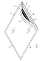
- a vacuum seal bag of the present invention comprises two membrane layers 1 to form three side ends 11, 12, 13, by ultrasonic welding, high frequency welding or other welding methods; whereas, a side end 14 where the two membrane layers 1 are not welded, is provided with a sealing structure which is a zip lock set 141 in this embodiment.
- a sealing structure can also be a seal set including two parts, with each part being affixed with the other (not shown in the drawings).
- an opening 1411 is formed to put in food products (not shown in the drawings) or other goods; whereas, when a vacuumizing operation is to be performed, the sealing structure of this embodiment, or the zip lock set 141, is sealed, and then air in the vacuum seal bag is extracted out by an electric air extracting device 5 (as shown in FIG. 8 ), a manual air extracting device (not shown in the drawings) or other air extracting device such as an electric dust catcher (not shown in the drawings), through an air extraction hole 10 that is provided on the vacuum seal bag, enabling the vacuum seal bag to be in a vacuum state, which facilitates the food products or the goods to be preserved in the vacuum seal bag for a long time.
- an electric air extracting device 5 as shown in FIG. 8
- a manual air extracting device not shown in the drawings
- other air extracting device such as an electric dust catcher
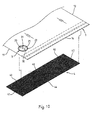
- the air extraction hole 10 of one membrane layer 1 of the vacuum seal bag is affixed with a first bonding layer 2 of a small area.
- An interior surface of the first bonding layer 2 is provided with glueware 20 (as shown in FIG. 7 ) and a vent-hole 21 which is connected with the air extraction hole 10 of the aforementioned membrane layer 1.
- An exterior side of the first bonding layer 2 is affixed with a second bonding layer 3 of a small area, an interior surface of the second bonding layer 3 is provided with glueware 30 (as shown in FIG.
- the second bonding layer 3 also includes a covering part 31 which can cover the aforementioned vent-hole 21 of the first bonding layer 2, as well as at least one vent-hole 32, 33 that is spaced with the covering part 31 by a distance.
- the vent-holes 32, 33 are tiny wavy slot holes respectively.
- air inside the vacuum seal bag can be extracted out at the vent-holes 32, 33 of the second bonding layer 3, through the air extraction hole 10 of one of the aforementioned membrane layers 1, the vent-hole 21 of the first bonding layer 2, as well as a small gap 301 (as shown in FIG. 6 and FIG. 7 ) between the first bonding layer 2 and the glueware 30 on the interior surface of the second bonding layer 3, by using outward suction force.
- the glueware 30 on the interior surface of the second bonding layer 3 can be bonded more tightly with the first bonding layer 3 by vacuum suction force in the vacuum seal bag, as suction force disappears.
- the first bonding layer 2 can be also bonded with one of the aforementioned membrane layers 1 by the glueware 20, so as to prevent ambient air from entering into the vacuum seal bag, thereby achieving a sealing effect.
- the interior surface of one membrane layer 1 that is provided with the air extraction hole 10, for the aforementioned vacuum seal bag can be also further welded with an air-guide membrane layer 4, which belongs to a prior art, by ultrasonic welding, high frequency welding or other welding methods.
- An area of that air-guide membrane layer 4 is a little smaller than that of the aforementioned membrane layer 1, and is welded with the aforementioned membrane layer 1 by three side ends 41, 42, 44 (as shown in FIG. 10 ); whereas, a gap 431 is formed (as shown in FIG.
- first bonding layer 2 and the second bonding layer 3 are all membranes made by a plastic material.
- first bonding layer 2 or the second bonding layer 3 can be further printed with a text (not shown in the drawings), a graph 22 or a mark, to facilitate aligning with the electric air extracting device 5, upon extracting out the air.
- the graph 22 is printed on the first bonding layer 2.
Abstract
A vacuum seal bag is provided. An air extracting operation is performed after an air extracting device (5) has been aligned with and covered on a vent-hole (32,33) of a second bonding layer (3); and air in the vacuum seal bag is extracted out at the vent-hole of the second bonding layer, through an air extraction hole (10) of the vacuum seal bag, a vent-hole (21) of a first bonding layer (2), as well as a small gap (301) between the first bonding layer and glueware (30) on an interior surface of the second bonding layer. When the vacuum operation is accomplished and stops, suction force disappears; therefore, the glueware (30) on the internal surface of the second bonding layer (3) is bonded with the first bonding layer (2) more tightly by the pressure difference between ambient air and the vacuum suction in the vacuum seal bag to prevent ambient air from entering into the vacuum seal bag to achieve a sealing effect.
Description
- The present invention relates to a vacuum seal bag, and more particularly to a vacuum seal bag which can be vacuumized directly without installing an air valve.
- For an ordinary vacuum seal bag that is used to collect food products or goods, a pre-built through-hole on an upper membrane layer or a lower membrane layer of the bag is installed with an air valve. Next, after an opening of the bag is put in with the food products or the goods, the opening is sealed by a sealing structure, followed by aligning a nozzle of a manual or an electric air extracting device, such as a dust catcher, with the air valve of the bag to extract out the air inside the bag to achieve a vacuum state, thereby assuring that the food products or the goods that are collected can be preserved for a long time. In addition, referring to
FIGS. 1 to 3 , for aconventional vacuum bag 3 which is provided with an air valve, anupper membrane layer 31 is provided with theair valve 4, and the air valve 4 (as shown inFIG. 2 andFIG. 3 ) is constituted by anupper cap 41, aplug 42, a plurality of O-rings positioning seat 45, avalve plate 46, avalve seat 47 and a gasket 48 (as shown inFIG. 3 ). The aforementionedconventional vacuum bag 3 that is provided with the air valve is found to have following drawbacks: - 1. Upon assembling the
upper cap 41, theplug 42, the O-rings positioning seat 45, thevalve plate 46, thevalve seat 47 and thegasket 48, of theair valve 4, theupper membrane layer 31 of the bag is affected by a small space of the closestlower membrane layer 32, allowing an assembling operation to be rather troublesome that manpower and labor hours can be wasted. - 2. As the
air valve 4 is provided with a lot of parts, cost is increased correspondingly. - 3. In using the
vacuum bag 3, when the food products or the goods are put into the bag, they will be in touch with thevalve seat 47 easily and therefore, it is easy to produce a gap that the vacuum function can be lost if thevacuum bag 3 is used many times repeatedly. - 4. As the food products or the goods can have different shapes, when the upper and
lower membrane layers upper cap 41 of theair valve 4 is to be aligned with an air extracting device (not shown in the drawings). Furthermore, if theupper cap 41 is aligned by exerting too much force, the collection, such as the food products or the goods, in the bag, can be squeezed. Even that if it is all right to squeeze the collection in the bag, the operation can still be inconvenient due to that the collection are provided with irregular shapes. - The primary object of the present invention is to provide a vacuum seal bag that an air extracting operation can be performed after an air extracting device has been aligned with and covered on a vent-hole of a second bonding layer, and that air inside the vacuum seal bag can be extracted out at the vent-hole of the second bonding layer, through an air extraction hole of the vacuum seal bag, a vent-hole of a first bonding layer, as well as a small gap between the first bonding layer and glueware on an interior surface of the second bonding layer, by using outward suction force.
- Another object of the present invention is to provide a vacuum seal bag which is provided with simple structures and can be vacuumized by directly collaborating with an air extracting device, without installing an air valve that is composed of complicated parts, thereby largely reducing manpower, labor hours and cost, correspondingly.
- Still another object of the present invention is to provide a vacuum seal bag which does not occupy space relatively to facilitate storing, packaging or transporting, as it is not necessary to install an air valve.
- To enable a further understanding of the said objectives and the technological methods of the invention herein, the brief description of the drawings below is followed by the detailed description of the preferred embodiments.
-
-
FIG. 1 shows a three-dimensional view of a conventional vacuum bag. -
FIG. 2 shows a three-dimensional exploded view of an air valve of a conventional vacuum bag. -
FIG. 3 shows an enlarged view of a cross section of a conventional vacuum bag that is assembled. -
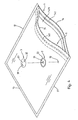
FIG. 4 shows a three-dimensional exploded view of an embodiment of the present invention. -
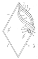
FIG. 5 shows a three-dimensional view of an embodiment of the present invention. -
FIG. 6 shows an enlarged view of a partial cross section after an embodiment of the present invention has been aligned with an air extracting device. -
FIG. 7 shows a re-enlarged view of a partial cross section of an embodiment of the present invention. -
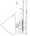
FIG. 8 shows an enlarged view of a partial cross section of an embodiment of the present invention, wherein a membrane layer is further welded with an air-guide membrane layer. -
FIG. 9 shows a three-dimensional rear view of an embodiment of the present invention, wherein a membrane layer has been further welded with an air-guide membrane layer. -
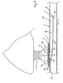
FIG. 10 shows a partial three-dimensional exploded view of an embodiment of the present invention, wherein a membrane layer has not been welded with an air-guide membrane layer. - Referring to
FIGS. 4 to 7 , a vacuum seal bag of the present invention comprises twomembrane layers 1 to form threeside ends side end 14 where the twomembrane layers 1 are not welded, is provided with a sealing structure which is a zip lock set 141 in this embodiment. However, that sealing structure can also be a seal set including two parts, with each part being affixed with the other (not shown in the drawings). When the sealing structure of this embodiment, or the zip lock set 141, is opened, an opening 1411 is formed to put in food products (not shown in the drawings) or other goods; whereas, when a vacuumizing operation is to be performed, the sealing structure of this embodiment, or thezip lock set 141, is sealed, and then air in the vacuum seal bag is extracted out by an electric air extracting device 5 (as shown inFIG. 8 ), a manual air extracting device (not shown in the drawings) or other air extracting device such as an electric dust catcher (not shown in the drawings), through anair extraction hole 10 that is provided on the vacuum seal bag, enabling the vacuum seal bag to be in a vacuum state, which facilitates the food products or the goods to be preserved in the vacuum seal bag for a long time. - The
air extraction hole 10 of onemembrane layer 1 of the vacuum seal bag is affixed with afirst bonding layer 2 of a small area. An interior surface of thefirst bonding layer 2 is provided with glueware 20 (as shown inFIG. 7 ) and a vent-hole 21 which is connected with theair extraction hole 10 of theaforementioned membrane layer 1. An exterior side of thefirst bonding layer 2 is affixed with asecond bonding layer 3 of a small area, an interior surface of thesecond bonding layer 3 is provided with glueware 30 (as shown inFIG. 7 ) to facilitate bonding at an upper side of the aforementionedfirst bonding layer 2, and thesecond bonding layer 3 also includes a coveringpart 31 which can cover the aforementioned vent-hole 21 of thefirst bonding layer 2, as well as at least one vent-hole part 31 by a distance. In this embodiment, the vent-holes air extracting device 5 is aligned with and covered on the vent-holes FIG. 6 ), the air extracting operation can be performed. In addition, air inside the vacuum seal bag can be extracted out at the vent-holes second bonding layer 3, through theair extraction hole 10 of one of theaforementioned membrane layers 1, the vent-hole 21 of thefirst bonding layer 2, as well as a small gap 301 (as shown inFIG. 6 andFIG. 7 ) between thefirst bonding layer 2 and theglueware 30 on the interior surface of thesecond bonding layer 3, by using outward suction force. On the other hand, when the vacuum operation is accomplished and stops, theglueware 30 on the interior surface of thesecond bonding layer 3 can be bonded more tightly with thefirst bonding layer 3 by vacuum suction force in the vacuum seal bag, as suction force disappears. In addition, thefirst bonding layer 2 can be also bonded with one of theaforementioned membrane layers 1 by theglueware 20, so as to prevent ambient air from entering into the vacuum seal bag, thereby achieving a sealing effect. - Furthermore, referring to
FIGS. 8 to 10 , the interior surface of onemembrane layer 1 that is provided with theair extraction hole 10, for the aforementioned vacuum seal bag, can be also further welded with an air-guide membrane layer 4, which belongs to a prior art, by ultrasonic welding, high frequency welding or other welding methods. An area of that air-guide membrane layer 4 is a little smaller than that of theaforementioned membrane layer 1, and is welded with theaforementioned membrane layer 1 by threeside ends FIG. 10 ); whereas, agap 431 is formed (as shown inFIG. 8 ) between aninner end 43 and theaforementioned membrane layer 1, wherein, an upper and lower surfaces of the air-guide membrane layer 4 are all provided with a plurality of air-guide slots 40 which facilitate the air inside the vacuum seal bag to be extracted out more smoothly and quickly, upon extracting out the air. - On the other hand, the aforementioned
first bonding layer 2 and thesecond bonding layer 3 are all membranes made by a plastic material. - In addition, the aforementioned
first bonding layer 2 or thesecond bonding layer 3 can be further printed with a text (not shown in the drawings), agraph 22 or a mark, to facilitate aligning with the electricair extracting device 5, upon extracting out the air. As thesecond bonding layer 3 of this embodiment is made by a transparent material, thegraph 22 is printed on thefirst bonding layer 2. - Accordingly, it is induced that the present invention is provided with following improved effects:
- 1. The structures are simple. The vacuum seal bag can be vacuumized by directly collaborating with the air extracting device, without installing the air valve that is constituted by complicated parts, which largely reduces manpower, labor hours and cost, correspondingly.
- 2. As it is not necessary to install the air valve, the vacuum seal bag does not occupy space relatively, which facilitates storing, packaging or transporting.
- 3. When the air extracting device is aligned with and covered on the vent-
holes second bonding layer 3, the air extracting operation can be performed; and the air inside the vacuum seal bag can be extracted out at the vent-holes second bonding layer 3 by the outward suction force, through theair extraction hole 10, the vent-hole 21 of thefirst bonding layer 2, and then thesmall gap 301 between thefirst bonding layer 2 and theglueware 30 on the interior surface of thesecond bonding layer 3. On the other hand, when the vacuum operation is accomplished and stops, theglueware 30 on the interior surface of thesecond bonding layer 3 can be bonded more tightly with thefirst bonding layer 2 by the vacuum suction force in the vacuum seal bag, as the suction force disappears, which can prevent the ambient air from entering into the vacuum seal bag, thereby achieving the sealing effect. - 4. Freshness of the food products in the vacuum seal bag can be preserved to avoid germs, thereby prolonging the lifetime of the food products.
- 5. The vacuum seal bag can be used repeatedly, thereby complying with the principle of environmental protection.
- It is of course to be understood that the embodiments described herein is merely illustrative of the principles of the invention and that a wide variety of modifications thereto may be effected by persons skilled in the art without departing from the spirit and scope of the invention as set forth in the following claims.
Claims (6)
- A vacuum seal bag comprising two membrane layers 1 that form three side ends 11, 12, 13 by welding, whereas a side end 14 where the two membrane layers 1 are not welded is provided with a sealing structure 141; when the sealing structure 141 is opened, an opening 1411 being formed to put in food products or other goods; when a vacuum operation is to be performed, the sealing structure 141 being sealed first, and then air being extracted out by an air extracting hole 10 provided on the vacuum seal bag, in association with an air extracting device 5, enabling the vacuum seal bag to be in a vacuum state; the air extraction hole 10 of one membrane layer 1 of the vacuum seal bag being affixed with a first bonding layer 2 of a small area, an interior surface of the first bonding layer 2 being provided with glueware 20 and being transfixed with a vent-hole 21 which is connected with the air extraction hole 10 of the aforementioned membrane layer 1; an exterior side of the first bonding layer 2 being affixed with a second bonding layer 3 of a small area, an interior surface of the second bonding layer 3 being provided with glueware 30 to facilitate bonding at an upper side of the aforementioned first bonding layer 2; the second bonding layer 3 also including a covering part 31 to cover the vent-hole 21 of the aforementioned first bonding layer 2 and more than one vent-hole 32, 33 that is spaced with the covering part 31 by a distance.
- The vacuum seal bag according to claim 1, wherein the first bonding layer 2 and the second bonding layer 3 are membranes made by a plastic material.
- The vacuum seal bag according to claim 1, wherein the first bonding layer 2 or the second bonding layer 3 is further printed with a text, a graph or a mark, to facilitate aligning with the air extracting device 5 upon extracting the air.
- A vacuum seal bag comprising two membrane layers 1 that form three side ends 11, 12, 13 by welding, whereas a side end 14 where the two membrane layers 1 are not welded is provided with a sealing structure 141, one membrane layer 1 is provided with an air extraction hole 10, and an interior surface of that membrane layer 1 is welded with an air-guide membrane layer 4 of a smaller area; the air-guide membrane layer 4 being provided with three side ends 41, 42, 44, a gap being formed between an inner end 43 and the aforementioned membrane layer 1, and each of upper and lower surfaces of the air-guide membrane layer 4 being provided with a plurality of air-guide slots 40; when the sealing structure 141 is opened, an opening 1411 being formed to put in food products or other goods; when a vacuum operation is to be performed, the sealing structure 141 being sealed first, and then air being extracted out by an air extracting hole 10 provided on the vacuum seal bag, in association with an air extracting device 5, enabling the vacuum seal bag to be in a vacuum state; the air inside the vacuum seal bag being extracted out more smoothly and quickly, by the air-guide slots 40 that are provided on the upper and lower surfaces of the air-guide membrane layer 4 which is welded with one of the aforementioned membrane layers 1; the air extraction hole 10 of one membrane layer 1 of the vacuum seal bag being affixed with a first bonding layer 2 of a small area, an interior surface of the first bonding layer 2 being provided with glueware 20 and being transfixed with a vent-hole 21 which is connected with the air extraction hole 10 of the aforementioned membrane layer 1; an exterior side of the first bonding layer 2 being affixed with a second bonding layer 3 of a small area, an interior surface of the second bonding layer 3 being provided with glueware 30 to facilitate bonding at an upper side of the aforementioned first bonding layer 2; the second bonding layer 3 also including a covering part 31 to cover the vent-hole 21 of the aforementioned first bonding layer 2 and more than one vent-hole 32, 33 that is spaced with the covering part 31 by a distance.
- The vacuum seal bag according to claim 4, wherein the first bonding layer 2 and the second bonding layer 3 are membranes made by a plastic material.
- The vacuum seal bag according to claim 4, wherein the first bonding layer 2 or the second bonding layer 3 is further printed with a text, a graph or a mark, to facilitate aligning with the air extracting device 5 upon extracting out the air.
Priority Applications (1)
| Application Number | Priority Date | Filing Date | Title |
|---|---|---|---|
| EP08021456A EP2196405A1 (en) | 2008-12-10 | 2008-12-10 | Vacuum seal bag |
Applications Claiming Priority (1)
| Application Number | Priority Date | Filing Date | Title |
|---|---|---|---|
| EP08021456A EP2196405A1 (en) | 2008-12-10 | 2008-12-10 | Vacuum seal bag |
Publications (1)
| Publication Number | Publication Date |
|---|---|
| EP2196405A1 true EP2196405A1 (en) | 2010-06-16 |
Family
ID=40469836
Family Applications (1)
| Application Number | Title | Priority Date | Filing Date |
|---|---|---|---|
| EP08021456A Withdrawn EP2196405A1 (en) | 2008-12-10 | 2008-12-10 | Vacuum seal bag |
Country Status (1)
| Country | Link |
|---|---|
| EP (1) | EP2196405A1 (en) |
Cited By (10)
| Publication number | Priority date | Publication date | Assignee | Title |
|---|---|---|---|---|
| CN102530395A (en) * | 2011-11-21 | 2012-07-04 | 北华大学 | Preservation method for precious raw hide |
| WO2013053131A1 (en) * | 2011-10-14 | 2013-04-18 | Chen wei ling | Detachable air valve for bag and use method thereof |
| NL2008887C2 (en) * | 2012-05-25 | 2013-11-26 | Bin Innovations Bv | System for marinating or brining food, container, valve and reservoir for use in the system. |
| CN104044799A (en) * | 2013-03-15 | 2014-09-17 | 张人堂 | Airtight bag with seal structure |
| US9499035B1 (en) | 2015-09-15 | 2016-11-22 | Sergey Chashchukhin | Vehicle cover |
| CN107022468A (en) * | 2017-06-09 | 2017-08-08 | 无锡市赛微生物技术有限公司 | A kind of instant culture medium plate collecting bag |
| CN109513271A (en) * | 2017-09-19 | 2019-03-26 | 西安蓝屿新风洁净技术有限公司 | A kind of lysozyme air cleaning filter |
| WO2019243116A1 (en) * | 2018-06-22 | 2019-12-26 | Koninklijke Philips N.V. | Patient interface valve arrangement |
| CN111186632A (en) * | 2018-11-15 | 2020-05-22 | 珠海润都制药股份有限公司 | Package for improving stability of medicine |
| CN112660594A (en) * | 2020-12-08 | 2021-04-16 | 宁波华丰包装有限公司 | Square three-dimensional vacuum compression bag |
Citations (8)
| Publication number | Priority date | Publication date | Assignee | Title |
|---|---|---|---|---|
| GB689714A (en) * | 1950-11-29 | 1953-04-01 | Wilts United Dairies Ltd | Improvements in and relating to airtight packages |
| DE3521373A1 (en) * | 1985-06-14 | 1986-12-18 | Heinrich Hermann Gmbh + Co, 7000 Stuttgart | Overpressure valve for a packaging container, in particular made of flexible material, and production method therefor |
| EP1108655A1 (en) * | 1999-02-05 | 2001-06-20 | Santoku Inc. | Preservation container for food or the like |
| WO2005000706A1 (en) * | 2003-05-30 | 2005-01-06 | Avery Dennison Corporation | Food bag release valve |
| US20050161465A1 (en) * | 2004-01-26 | 2005-07-28 | Miller Richard T. | Valve element |
| WO2006012528A2 (en) * | 2004-07-23 | 2006-02-02 | Alcoa Inc. | Storage system having a disposable vacuum bag |
| WO2007038299A2 (en) * | 2005-09-23 | 2007-04-05 | The Glad Products Company | Valve element |
| WO2008021630A2 (en) * | 2006-08-07 | 2008-02-21 | The Glad Products Company | Vacuum storage bag |
-
2008
- 2008-12-10 EP EP08021456A patent/EP2196405A1/en not_active Withdrawn
Patent Citations (8)
| Publication number | Priority date | Publication date | Assignee | Title |
|---|---|---|---|---|
| GB689714A (en) * | 1950-11-29 | 1953-04-01 | Wilts United Dairies Ltd | Improvements in and relating to airtight packages |
| DE3521373A1 (en) * | 1985-06-14 | 1986-12-18 | Heinrich Hermann Gmbh + Co, 7000 Stuttgart | Overpressure valve for a packaging container, in particular made of flexible material, and production method therefor |
| EP1108655A1 (en) * | 1999-02-05 | 2001-06-20 | Santoku Inc. | Preservation container for food or the like |
| WO2005000706A1 (en) * | 2003-05-30 | 2005-01-06 | Avery Dennison Corporation | Food bag release valve |
| US20050161465A1 (en) * | 2004-01-26 | 2005-07-28 | Miller Richard T. | Valve element |
| WO2006012528A2 (en) * | 2004-07-23 | 2006-02-02 | Alcoa Inc. | Storage system having a disposable vacuum bag |
| WO2007038299A2 (en) * | 2005-09-23 | 2007-04-05 | The Glad Products Company | Valve element |
| WO2008021630A2 (en) * | 2006-08-07 | 2008-02-21 | The Glad Products Company | Vacuum storage bag |
Cited By (14)
| Publication number | Priority date | Publication date | Assignee | Title |
|---|---|---|---|---|
| WO2013053131A1 (en) * | 2011-10-14 | 2013-04-18 | Chen wei ling | Detachable air valve for bag and use method thereof |
| CN103958950A (en) * | 2011-10-14 | 2014-07-30 | 陈玮伶 | Detachable air valve for bag and use method thereof |
| CN103958950B (en) * | 2011-10-14 | 2016-02-10 | 陈玮伶 | Removable bag air valve and using method thereof |
| CN102530395A (en) * | 2011-11-21 | 2012-07-04 | 北华大学 | Preservation method for precious raw hide |
| NL2008887C2 (en) * | 2012-05-25 | 2013-11-26 | Bin Innovations Bv | System for marinating or brining food, container, valve and reservoir for use in the system. |
| CN104044799A (en) * | 2013-03-15 | 2014-09-17 | 张人堂 | Airtight bag with seal structure |
| US9499035B1 (en) | 2015-09-15 | 2016-11-22 | Sergey Chashchukhin | Vehicle cover |
| CN107022468A (en) * | 2017-06-09 | 2017-08-08 | 无锡市赛微生物技术有限公司 | A kind of instant culture medium plate collecting bag |
| CN107022468B (en) * | 2017-06-09 | 2023-11-10 | 无锡市食品安全检验检测中心 | Ready-to-use culture medium plate storage bag |
| CN109513271A (en) * | 2017-09-19 | 2019-03-26 | 西安蓝屿新风洁净技术有限公司 | A kind of lysozyme air cleaning filter |
| WO2019243116A1 (en) * | 2018-06-22 | 2019-12-26 | Koninklijke Philips N.V. | Patient interface valve arrangement |
| CN111186632A (en) * | 2018-11-15 | 2020-05-22 | 珠海润都制药股份有限公司 | Package for improving stability of medicine |
| CN112660594A (en) * | 2020-12-08 | 2021-04-16 | 宁波华丰包装有限公司 | Square three-dimensional vacuum compression bag |
| CN112660594B (en) * | 2020-12-08 | 2022-07-05 | 宁波华丰包装有限公司 | Square three-dimensional vacuum compression bag |
Similar Documents
| Publication | Publication Date | Title |
|---|---|---|
| EP2196405A1 (en) | Vacuum seal bag | |
| US6581641B2 (en) | One-way valve for use with vacuum pump | |
| WO2005070137A3 (en) | User installable vacuum seal apparatus for storage bags | |
| EP1739024A3 (en) | Reclosable vacuum storage bag having flat resealable means | |
| US20150060446A1 (en) | Rubber seal for vacuum receptacle and lid for the receptacle using the same | |
| KR20080017051A (en) | Device and method for evacuating a storage bag | |
| US20120099806A1 (en) | Vacuum compression storage bags | |
| KR20140061540A (en) | Detachable air valve for bag and use method thereof | |
| US8720468B2 (en) | Pouch air valve and structure adopted on a sealed pouch and method of use | |
| JPH04189752A (en) | Opening and closing device for bag evacuation opening | |
| US8936044B1 (en) | Pouch air valve used on sealing pouches | |
| CN205034502U (en) | Sealed lid of vacuum control | |
| CN201372035Y (en) | Vacuum sealing bag | |
| CN204323955U (en) | Vacuum seal bottle cap | |
| CN206580074U (en) | A kind of rice bag | |
| KR101876324B1 (en) | Vacuum desiccator | |
| US20070017926A1 (en) | Nozzle device for vacuum container | |
| JP3166615U (en) | Vacuum seal plug | |
| CN207390023U (en) | A kind of vacuum compression bag | |
| CN213293275U (en) | High-barrier transparent freshness protection package | |
| JP2007153436A (en) | Vacuum packaging apparatus | |
| CN218930396U (en) | Novel vacuum compression bag | |
| CN218259696U (en) | Food fresh-keeping vacuum zipper bag | |
| CN214609231U (en) | Storage device | |
| CN201236001Y (en) | Vacuum compression bag |
Legal Events
| Date | Code | Title | Description |
|---|---|---|---|
| PUAI | Public reference made under article 153(3) epc to a published international application that has entered the european phase |
Free format text: ORIGINAL CODE: 0009012 |
|
| AK | Designated contracting states |
Kind code of ref document: A1 Designated state(s): AT BE BG CH CY CZ DE DK EE ES FI FR GB GR HR HU IE IS IT LI LT LU LV MC MT NL NO PL PT RO SE SI SK TR |
|
| AX | Request for extension of the european patent |
Extension state: AL BA MK RS |
|
| AKY | No designation fees paid | ||
| STAA | Information on the status of an ep patent application or granted ep patent |
Free format text: STATUS: THE APPLICATION IS DEEMED TO BE WITHDRAWN |
|
| 18D | Application deemed to be withdrawn |
Effective date: 20101217 |