EP2195136B1 - Antriebsmechanismuskonfiguration für arbeitsmaschine, insbesondere für werkzeugmaschinenantrieb - Google Patents
Antriebsmechanismuskonfiguration für arbeitsmaschine, insbesondere für werkzeugmaschinenantrieb Download PDFInfo
- Publication number
- EP2195136B1 EP2195136B1 EP08801033A EP08801033A EP2195136B1 EP 2195136 B1 EP2195136 B1 EP 2195136B1 EP 08801033 A EP08801033 A EP 08801033A EP 08801033 A EP08801033 A EP 08801033A EP 2195136 B1 EP2195136 B1 EP 2195136B1
- Authority
- EP
- European Patent Office
- Prior art keywords
- machine
- revolving
- torque motor
- rotor
- stator
- Prior art date
- Legal status (The legal status is an assumption and is not a legal conclusion. Google has not performed a legal analysis and makes no representation as to the accuracy of the status listed.)
- Not-in-force
Links
- 238000004804 winding Methods 0.000 claims description 14
- 230000002706 hydrostatic effect Effects 0.000 claims description 12
- 238000005461 lubrication Methods 0.000 claims description 5
- 239000010720 hydraulic oil Substances 0.000 claims description 4
- 238000010276 construction Methods 0.000 description 12
- 239000003921 oil Substances 0.000 description 6
- 239000000314 lubricant Substances 0.000 description 3
- 239000013598 vector Substances 0.000 description 3
- 230000005284 excitation Effects 0.000 description 2
- 238000004519 manufacturing process Methods 0.000 description 2
- XLYOFNOQVPJJNP-UHFFFAOYSA-N water Substances O XLYOFNOQVPJJNP-UHFFFAOYSA-N 0.000 description 2
- 238000001816 cooling Methods 0.000 description 1
- 230000000694 effects Effects 0.000 description 1
- 230000005672 electromagnetic field Effects 0.000 description 1
- 239000007788 liquid Substances 0.000 description 1
- 238000003754 machining Methods 0.000 description 1
- 238000012423 maintenance Methods 0.000 description 1
- 230000013011 mating Effects 0.000 description 1
- 238000012986 modification Methods 0.000 description 1
- 230000004048 modification Effects 0.000 description 1
- 238000004806 packaging method and process Methods 0.000 description 1
- 239000004033 plastic Substances 0.000 description 1
- 229920003023 plastic Polymers 0.000 description 1
- 239000004753 textile Substances 0.000 description 1
Images



Classifications
-
- B—PERFORMING OPERATIONS; TRANSPORTING
- B23—MACHINE TOOLS; METAL-WORKING NOT OTHERWISE PROVIDED FOR
- B23Q—DETAILS, COMPONENTS, OR ACCESSORIES FOR MACHINE TOOLS, e.g. ARRANGEMENTS FOR COPYING OR CONTROLLING; MACHINE TOOLS IN GENERAL CHARACTERISED BY THE CONSTRUCTION OF PARTICULAR DETAILS OR COMPONENTS; COMBINATIONS OR ASSOCIATIONS OF METAL-WORKING MACHINES, NOT DIRECTED TO A PARTICULAR RESULT
- B23Q5/00—Driving or feeding mechanisms; Control arrangements therefor
- B23Q5/02—Driving main working members
- B23Q5/04—Driving main working members rotary shafts, e.g. working-spindles
- B23Q5/10—Driving main working members rotary shafts, e.g. working-spindles driven essentially by electrical means
-
- H—ELECTRICITY
- H02—GENERATION; CONVERSION OR DISTRIBUTION OF ELECTRIC POWER
- H02K—DYNAMO-ELECTRIC MACHINES
- H02K5/00—Casings; Enclosures; Supports
- H02K5/04—Casings or enclosures characterised by the shape, form or construction thereof
- H02K5/16—Means for supporting bearings, e.g. insulating supports or means for fitting bearings in the bearing-shields
- H02K5/173—Means for supporting bearings, e.g. insulating supports or means for fitting bearings in the bearing-shields using bearings with rolling contact, e.g. ball bearings
- H02K5/1735—Means for supporting bearings, e.g. insulating supports or means for fitting bearings in the bearing-shields using bearings with rolling contact, e.g. ball bearings radially supporting the rotary shaft at only one end of the rotor
-
- B—PERFORMING OPERATIONS; TRANSPORTING
- B23—MACHINE TOOLS; METAL-WORKING NOT OTHERWISE PROVIDED FOR
- B23Q—DETAILS, COMPONENTS, OR ACCESSORIES FOR MACHINE TOOLS, e.g. ARRANGEMENTS FOR COPYING OR CONTROLLING; MACHINE TOOLS IN GENERAL CHARACTERISED BY THE CONSTRUCTION OF PARTICULAR DETAILS OR COMPONENTS; COMBINATIONS OR ASSOCIATIONS OF METAL-WORKING MACHINES, NOT DIRECTED TO A PARTICULAR RESULT
- B23Q2220/00—Machine tool components
- B23Q2220/004—Rotary tables
Definitions
- the invention concerns the arrangement of a revolving table of big machine-tools, in particular boring mills created by a torque motor and a mounting system.
- the electromotor is of usual construction. Its main parts are a stable stator and a revolving rotor that are mutually separated by an air space.
- the supplied electrical energy is changed, by means of electro-magnetic field in the air space, at mechanical one, which is given over by the motor, at the rotor shaft, to the driven device.
- it is usually constructed an electromotor with a long rotor of a smaller diameter.
- the force of the electromotor, and by this the load, is created so that the force vector is a little one, but it is acting In a greater length (the length of the motor) so, that the small vectors are added together.
- the connection of the electromotor with the gearbox has a task to convert the high engine speed and the low torque to low engine speed and high torque, which are necessary for driving those machine-tools.
- Such a constructional disposition is bringing many disadvantages, among others also a necessity to use great and complicated gearboxes.
- Using of gearboxes of complicated constructions takes many problems with, such as a play between gearings, which causes noise and inexactness. The great complicity of the device is not negligible, too, as it is causing high production expenses.
- an assembly machine comprises a machine frame, a plurality of work stations arranged on a circular carrier plate secured on the surface of the machine frame, and a rotary dish that is rotationally driven in cycles and arranged concentrically with the carrier plate.
- the rotary dish protrudes along the circumference of the carrier plate and forms a ring-shaped support surface for work pieces that surround the carrier plate.
- the machine frame is a cast machine component that comprises a table-like substructure and a console on the top side with a ring-shaped mounting surface for receiving a drive for the rotary dish.
- the rotary dish drive is a direct drive that comprises a ring-shaped stator with electrical windings that is secured on the mounting surface, and a rotor fitted with permanent magnets. The rotor forms a carrier for and is detachably connected with the rotary dish.
- the purpose of the invention is to create such arrangement of a revolving table of big machine-tools, in particular boring mills, that will make possible a precise starting-up and stopping of the machine-tool table with great mass.
- This task fulfills and the above-mentioned disadvantages replaces arrangement of a revolving table of a big machine-tools, in particular boring mills, the subject matter of which consists in the fact, that the integral part of its stable part is a stator of the torque motor, and the integral part of its revolving part is a rotor of the torque motor, where the both the rotor and the stator of the torque motor are aligned axially to each other and to the machine central axe and are fixed to the mounting system, the ratio of the stator diameter to the stator height of the torque motor being greater than 2.
- the motor torque is greater than 10.000 Nm and the motor has a greater number of poles, usually greater than 100.
- the revolving table when used for great machine-tools, e.g. boring mills, has its stable part formed by machine support, in which the stator of the torque motor is fixed, fitted by at least one winding, while the revolving part is created by machine working plate, whose part forms the rotor of the torque machine fitted by at least one permanent magnet, both the rotor and the stator of the torque motor being aligned axially to each other and to the machine central axe, too, and for the axial alignment of the working plate and of the rotor of the torque motor toward the machine central axe, these parts are fixed in the mounting system, which is created by a pin fixed in the machine support, on which a radial bearing is mounted, on which the working plate is set up, while for the revolving mounting of the working plate, between the machine support and the working plate, at their proximal end, there is mounted the radial bearing and taken out the lubricant system conduit, and at the distant end of the working plate there is a hydrostatic mounting
- the drive for machine is modified by construction for using as a generator for electric energy production.
- a generator whose basic construction part is the torque motor, has its stable part made by a frame of the electric machine, in which there is mounted the stator of the torque motor fitted by at least one winding, while the revolving part is created by the flange of the electric machine, to which there is mounted the driving shaft and the rotor of the torque motor fitted by at least one rotor excitation coil, both the rotor and the stator of the torque motor being axially aligned towards the central axe, and to secure the revolving movement, both the stable and the revolving part are fixed to the mounting system consisting of an external ring and an internal ring of the annular bearing.
- the drive for machines modified by construction for using at radars has in its stable part, formed by the radar basis, mounted the stator of the torque motor equipped by at least one winding and in its revolving part, formed by the radar revolving part, fixed the rotor of the torque motor equipped by at least one permanent magnet, both the rotor and stator of the torque motor being axially aligned towards the radar central axe, and to secure the rotating movement, both the stable and the revolving part are fixed to the mounting system consisting of the external ring and the internal ring of the annular bearing.
- the main advantage of the new arrangement of a revolving table of a big machine-tools, in particular boring mills, is the fact that there are any gears missing and its construction is very simple one.
- the drive is formed only by two parts, which are the machine support and the working plate. It is necessary to make a sufficiently efficient torque motor for this construction (with high torque), which will form a part of the machine driving.
- the torque motor has to have a sufficient force, to be able to move or position the machined parts with a mass of the order of metric tons and more. From this reason, it is necessary to use a motor with nominal torque of c. 10.000 Nm and more. It seems that the torque motor is with the greatest advantage for that reason, while being characterized by great diameter and small length.
- the force vector is great (i.e. it disposes by great torque, but it takes effect at smaller length).
- the rate D : h is higher then one for the torque motors.
- the rate D : h is smaller than one.
- the torque motors that can be used for working machines have the rate D : H higher than 2.
- the torque motor is formed by two concentric parts with higher diameter and smaller height, which is why it is not much appropriate to be mounted in a cage. But thanks its form, it is ideal for direct mounting, e.g. to a machine-tool or to the driving of a crane pivot and other similar industrial devices having a central swivel plate, and this by such a way that it should make its integral part. This motor is also ideal to deduce great torques, a classical motor being no match for, because for such a torque (force) it would be too great or it would require a gear-box.
- the torque motor forms two centralized rings, which are the stator with a winding and the rotor equipped by permanent magnets. These rings are than forming an integrated part of the machine-tool.
- fig. 1 is a schematic view at the basic constructional disposition of the working machine driving
- fig. 2 illustrates the driving construction parts for machine-tools - boring mill in a longitudinal section
- fig. 2a represents the driving construction parts for machine-tools with a simplified mounting system
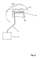
- fig. 2b represents a detailed view at the hydrostatic system
- fig. 3 represents a view at the machine in the execution as a torque generator
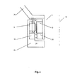
- fig. 4 represents a view at the driving of great radars rotating equipments.
- the basic arrangement of the working machine drive 1 according this invention is demonstrated at the fig. 1 .
- the parts of drive 1 in this execution are ordered symmetrically around the machine axe 13 .
- Individual parts of the machine drive 1 are formed by the torque motor 3 , which is its integral part, and the mounting system 27 . It is dealing about the liquid cooled more-poles permanently excited alternate synchronic motor.
- This one is formed by the stator 9 of the torque motor 3 , which is an integral part of the stable part 24 of the drive 1 , and by the rotor 10 of the torque motor 3 , which is an integral part of the revolving part 25 , both the rotor 10 and the stator 9 of the torque motor 3 being axially aligned one to other, as also to the axe 13 of the machine.
- the stable and also the revolving part, 24 and 25 , of the machine drive 1 there is mounted the stable and also the revolving part, 24 and 25 , of the machine drive 1 .
- the stable part 24 is fixed to the external ring 19 of the annual bearing, while the revolving part 25 of the driving 1 is fixed at the internal ring 20 of the annual bearing.
- the function of the drive 1 for machines is the following.
- the excitation current is starting to flow in the winding 15 of the stator 9 bobbins in such a way that it creates the revolving magnetic field.
- This field brings in the movement the rotor 10 excited by the permanent magnets 16 , by which contemporaneously also the revolving part 25 fixed in the mounting system 27 is brought to the movement.
- the drive 1 designed for a big machine-tool, where it is necessary to drive revolving tables or other positioning equipment is shown at fig. 2 .
- the drive 1 for a boring mill includes the torque motor 3 , the mounting system 27 , the revolving part 25 of the machine drive 1 formed by the working plate 5 of the machine-tool, and the stable part 24 of the machine drive 1 formed by the machine support 2 .
- the torque motor 3 which is an integral part of the machine-tool, is formed by two concentric rings, one of them being the stator 9 fitted by the winding 15 and mounted in the machine support 2 , which is - in this case - the machine supporting frame, and the other being the rotor 10 with permanent magnets 16 , which is fixed to the revolving working plate 5 .
- the stator 9 is mounted externally to the rotor 10 and both these parts are axially aligned one to other, as also to the central pin 4 , which is fixed in the machine support 2 , and for the coaxial alignment of the working plate 2 and of the rotor 10 of the torque motor 3 towards the machine central axe 13 are these parts fixed in the mounting system 27 , which - in this case - is formed by a pin 4 , at which it is mounted the radial bearing 6 , at which it is mounted the working plate 5 , while for the revolving mounting of the working plate 5 , between the machine support 2 and the working plate 5 , at their proximal end, there is mounted the radial bearing 6 and brought out the lubrication system conduit 11 and at the distant end, there is mounted the hydrostatic system 28 .
- the hydrostatic system 28 is formed by the top face 32 and the bottom face 31 , which is equipped by pockets 34 for keeping the hydraulic oil. To these pockets 34 there is connected the hydrostatic conduit 8 of the hydraulic oil, by which the latter is brought from hydraulic aggregate 33 to hydrostatic system 28 .
- the drive for machine-tool - boring mill is the following.
- the torque motor 3 is working in this case identically as described here-above.
- the revolving part 25 formed by the working plate 5 serves for fixing of machined components.
- the stable part 24 is formed by the machine support 2 of the machine-tool, which is the supporting frame.
- the revolving magnetic field generated by the exciting current actuates the rotor 10 fixed at the revolving part 25 .
- the revolving part 25 mounted at the radial bearing 6 rotates round the pin 4 , on which the bearing is fixed. Its horizontal position by the rotation is secured by the axial bearing 7 at one end, and at the other end it is secured by the hydrostatic system 28 .
- This system of working plate mounting is formed by two mating faces, the lower face 31 having cavities (pockets) in itself, which are connected to the pressure system, from which the oil is forced under pressure to these pockets.
- the other, superior face 32 is a flat one. It is ground and hard, because of sinking of frictional forces and of the lifetime. That superior face 32 is enclosing the oil in the pockets, and the oil is, under pressure, upholding the working plate 5 at the oil film.
- the oil pressure is generated by the hydraulic aggregate 33 (not shown at the picture) and the oil is brought to the pockets 34 through the pipes 35 .
- FIG. 2a Further variant mounting of the working plate 5 is shown at the fig. 2a . From this figure it is visible, that for the revolving mounting of the working plate 5 , between the machine support 2 and the working plate 5 , at their proximal end, there is mounted the radial bearing 6 and brought out the lubrication system conduit 11 and at the distant end there is mounted the axial bearing 7 connected to the conduit 11 of the lubrication system.
- the drive 1 execution is its constructional modification suitable for using as a torque generator.
- the machine driving 1 of this construction is shown at the fig. 3 .
- the drive 1 for machines has its stable part 24 formed by the frame 21 of the electric machine, in which there is mounted the stator 9 of the torque motor 3 equipped by at least one winding 15 , while the revolving part 25 is formed by the flange 22 of the electric machine, to which it is mounted the driveshaft 23 and the rotor 10 of the torque motor 3 equipped by at least one exciting winding 18 of the rotor 10 , both the rotor 10 and the stator 9 of the torque motor 3 being aligned axially against the central axe 13 , and to assure the rotating movement, the stable and the revolving part, 24 and 25 , are fixed to the mounting system 27 , which is formed by external ring 19 and internal ring 20 of the annular bearing.
- the drive for a generator is the following.
- the torque motor 3 is working in this case identically as described here-above.
- the revolving part 25 formed by the flange 22 serves for the mounting of the shaft 23 .
- the stable part 24 is formed by the frame 21 of the electric machine, on which the stator 9 with the winding 15 is mounted.
- the revolving magnetic field formed by the exciting current takes in movement the rotor 10 mounted at the revolving part 25 .
- Both, the revolving part 25 and the stable part are mounted at the mounting system 27 . In this case it concerns the annular bearing formed by external ring 19 and internal ring 20 .
- the stable part 24 is mounted to the external ring 19 of the annular bearing and assures a firm connection between the stator 9 and the frame 21 of the electric machine, while the revolving part 25 of the machine drive 1 is mounted at the internal ring 20 of the annular bearing and assures the rotating movement of the revolving part 25 , and further also the rotor 10 and stator 9 axial alignment against the axe 13 of the torque generator.
- the drive 1 has in its stable part 24 mounted the stator 9 of the torque motor 3 equipped by at least one winding 15 and in its revolving part 25 mounted the rotor 10 of the torque motor 3 equipped by at least one permanent magnet 16 , both the rotor 10 and the stator 9 of the torque motor 3 being axially aligned towards the central axe 13 of the radar.
- both the stable part 24 and the revolving part 25 are fixed to the mounting system 27 consisting of the external ring 19 and the internal ring 20 of the annual bearing.
- the drive function for radar is the following.
- the torque motor 3 is working in this case identically as described here-above.
- the revolving part 25 formed by an arm serves for mounting of the radar rotating parts 30 .
- the stable part 24 is formed by the radar basis 29 and is designed for mounting of the stator 9 with the winding 15 .
- the revolving magnetic field created by the exciting current actuates the rotor 10 mounted at the revolving part 25 .
- Both the revolving part 25 and the stable part 24 are arranged at the mounting system 27 . In this case it concerns the annular bearing formed by the external ring 19 and the internal ring 20 .
- the stable part 24 is mounted to the external ring 19 of the annular bearing and assures a firm connection between the stator 9 and the support 29 of the radar, while the revolving part 25 of the machine drive 1 is mounted at the internal ring 20 of the annular bearing and assures the rotating movement of the revolving part 25 , and further also the axial alignment of the rotor 10 and stator 9 towards the radar axe 13 .
- Arrangement of a revolving table of big machine-tools is suitable to generate a great force, where it is not a necessity of high speed.
- the ideal applications as e.g. by the boring mill, revolving mill, pivot of a great crane, radio locator, wind power station, water power station, come out from these requirements, this driving is possible to use for function of generator, where it forms directly a part of the revolving machinery (turbines, propellers), and no gearings are needed.
Landscapes
- Engineering & Computer Science (AREA)
- Mechanical Engineering (AREA)
- Power Engineering (AREA)
- Connection Of Motors, Electrical Generators, Mechanical Devices, And The Like (AREA)
- Turning (AREA)
Claims (2)
- Der Aufbau des Drehtisches einer großen Bearbeitungsmaschine, hauptsächlich einer Karussell-Drehbank, die aus einem Momentmotor (3) und einem Lagersystem (27) besteht, auf dem ein drehbarer Teil (25) und ein fester Teil (24) angeordnet sind, wo den integralen Bestandteil des festen Teils (24) der Maschine, der aus einem Maschinengestell (2) besteht, der Ständer (9) des Momentmotors (3) darstellt, der mit mindestens einer Windung ausgestattet ist, und wo den integralen Bestandteil des drehbaren Teils (25) der Maschine, der aus einer Arbeitsplatte (5) der Maschine besteht, der Rotor (10) des Momentmotors darstellt, der mit mindestens einem Dauermagnet (16) ausgestattet ist, wo der Rotor (10) sowie der Ständer (9) des Momentmotors (3) einander gegenüber und gegenüber der Achse (13) der Maschine koaxial angeordnet sind, und an dem Lagersystem (27) fest angeschlossen sind, das aus einem Bolzen (4) besteht, der in dem Maschinengestell (2) befestigt ist, auf dem ein Querlage (6) angeordnet ist, auf dem die Arbeitsplatte (5) gelegt ist, dagegen für die drehbare Lagerung der Arbeitsplatte (5) zwischen dem Maschinengestell (2) und der Arbeitsplatte (5) auf ihrem proximalen Ende ein Querlager (6) angeordnet und die Leitung des Schmierölsystems (11) ausgeführt ist, wobei das Verhältnis des Durchmessers (D) vom Rotor (10) zur Höhe (h) des Ständers (9) des Momentmotors (3) grösser als 2 ist, dadurch gekennzeichnet, dass a Drehmoment des Motors mehr als 10.000 Nm beträgt und der Motor über mehr als 100 Pole verfügt und am distalen Ende zur Sicherung der horizontalen Lage des drehbaren Teils (25) das Axiallager (7) angeordnet ist, das an die Leitung (11) des Schmierölsystems oder an das hydrostatisches System (28) angeschlossen ist.
- Der Aufbau des Drehtisches einer großen Bearbeitungsmaschine, hauptsächlich einer Karussell-Drehbank, nach Anspruch 1, dadurch gekennzeichnet, dass das hydrostatische System aus einer oberen Fläche (32) und einer unteren Fläche (31) besteht, die mit Taschen (34) für die Aufbewahrung des hydraulischen Öls ausgestattet ist, an die die hydrostatische Leitung (8) des hydraulischen Öls angeschlossen ist, durch die es in das hydrostatische System (28) aus dem hydraulischen Aggregat (33) geführt ist.
Priority Applications (1)
| Application Number | Priority Date | Filing Date | Title |
|---|---|---|---|
| PL08801033T PL2195136T3 (pl) | 2007-08-22 | 2008-08-20 | Układ mechanizmu napędowego maszyny roboczej, zwłaszcza obrabiarki |
Applications Claiming Priority (2)
| Application Number | Priority Date | Filing Date | Title |
|---|---|---|---|
| CZ20070572A CZ2007572A3 (cs) | 2007-08-22 | 2007-08-22 | Usporádání pohonu pracovního stroje, zejména pro pohon obrábecího stroje |
| PCT/CZ2008/000098 WO2009024104A2 (en) | 2007-08-22 | 2008-08-20 | Driving mechanism configuration of working machine, especially for machine-tool drive |
Publications (2)
| Publication Number | Publication Date |
|---|---|
| EP2195136A2 EP2195136A2 (de) | 2010-06-16 |
| EP2195136B1 true EP2195136B1 (de) | 2012-11-28 |
Family
ID=40345783
Family Applications (1)
| Application Number | Title | Priority Date | Filing Date |
|---|---|---|---|
| EP08801033A Not-in-force EP2195136B1 (de) | 2007-08-22 | 2008-08-20 | Antriebsmechanismuskonfiguration für arbeitsmaschine, insbesondere für werkzeugmaschinenantrieb |
Country Status (5)
| Country | Link |
|---|---|
| EP (1) | EP2195136B1 (de) |
| CZ (1) | CZ2007572A3 (de) |
| ES (1) | ES2399570T3 (de) |
| PL (1) | PL2195136T3 (de) |
| WO (1) | WO2009024104A2 (de) |
Family Cites Families (4)
| Publication number | Priority date | Publication date | Assignee | Title |
|---|---|---|---|---|
| US5239892A (en) * | 1990-08-27 | 1993-08-31 | Mitutoyo Corporation | Rotating device |
| DE19918082B4 (de) * | 1999-04-21 | 2005-09-08 | Deckel Maho Gmbh | Universal-Werkzeugmaschine |
| DE10204965C1 (de) * | 2002-02-06 | 2003-07-10 | Akb Automationskomponenten Und | Montagemaschine |
| DE10358943A1 (de) * | 2003-12-15 | 2005-07-14 | Fertigungstechnik Weissenfels Gmbh | Werkstücktisch |
-
2007
- 2007-08-22 CZ CZ20070572A patent/CZ2007572A3/cs unknown
-
2008
- 2008-08-20 EP EP08801033A patent/EP2195136B1/de not_active Not-in-force
- 2008-08-20 PL PL08801033T patent/PL2195136T3/pl unknown
- 2008-08-20 ES ES08801033T patent/ES2399570T3/es active Active
- 2008-08-20 WO PCT/CZ2008/000098 patent/WO2009024104A2/en not_active Ceased
Also Published As
| Publication number | Publication date |
|---|---|
| WO2009024104A3 (en) | 2009-04-16 |
| EP2195136A2 (de) | 2010-06-16 |
| ES2399570T3 (es) | 2013-04-02 |
| CZ2007572A3 (cs) | 2009-03-04 |
| WO2009024104A2 (en) | 2009-02-26 |
| PL2195136T3 (pl) | 2013-04-30 |
Similar Documents
| Publication | Publication Date | Title |
|---|---|---|
| US20080289440A1 (en) | Linear/Rotary Drive Assembly | |
| EP2133982A2 (de) | Elektrische Maschine mit integriertem magnetischen Getriebe | |
| US8358044B2 (en) | Electric machine apparatus with integrated, high torque density magnetic gearing | |
| JP5460566B2 (ja) | アキシャルギャップ型回転電機 | |
| JP6106660B2 (ja) | 電気機械エネルギー変換器のステータとロータとの間の空隙を維持する機械組立体 | |
| US20080191570A1 (en) | Pivot Bearing Device, Particularly for a Rotating circular Table of a Machine Tool | |
| EP1916758A2 (de) | Elektromagnetische Maschine mit Doppelrotor | |
| US20130181562A1 (en) | Dual-rotor machine | |
| US10454342B2 (en) | Rotational movement control of an electric generator by means of a turning device | |
| EP3294623B1 (de) | Schiffsantriebsvorrichtung, gondeleinheit und schiff | |
| CN101707409A (zh) | 具有空气静力轴承和分段环形马达的ct扫描器机架 | |
| US20110273063A1 (en) | Electromechanical device | |
| US10027189B2 (en) | Electric rotating machine | |
| CN104904103B (zh) | 具有两个同轴的转子的机器 | |
| US10958121B2 (en) | Rotating electrical machine | |
| WO2015193734A1 (en) | Rotational movement multiplier | |
| US20130088103A1 (en) | Synchronic Wind Turbine Generator | |
| WO2000037308A1 (en) | Turnable propeller device for a ship, an offshore structure or equivalent | |
| US20120013211A1 (en) | Electric motor having a selectively adjustable base speed | |
| CN108488325B (zh) | 三速输出行星齿轮减速机 | |
| EP3017529B1 (de) | Reduzierung der lagerkräfte bei einer elektrischen maschine | |
| JP2012097730A (ja) | 流体発電装置 | |
| EP2195136B1 (de) | Antriebsmechanismuskonfiguration für arbeitsmaschine, insbesondere für werkzeugmaschinenantrieb | |
| WO2001035517A1 (en) | Wind turbine/generator assembly | |
| EP1570565A1 (de) | Integrierter elektromotor und traktionsantrieb |
Legal Events
| Date | Code | Title | Description |
|---|---|---|---|
| PUAI | Public reference made under article 153(3) epc to a published international application that has entered the european phase |
Free format text: ORIGINAL CODE: 0009012 |
|
| 17P | Request for examination filed |
Effective date: 20100322 |
|
| AK | Designated contracting states |
Kind code of ref document: A2 Designated state(s): AT BE BG CH CY CZ DE DK EE ES FI FR GB GR HR HU IE IS IT LI LT LU LV MC MT NL NO PL PT RO SE SI SK TR |
|
| AX | Request for extension of the european patent |
Extension state: AL BA MK RS |
|
| 17Q | First examination report despatched |
Effective date: 20101230 |
|
| GRAC | Information related to communication of intention to grant a patent modified |
Free format text: ORIGINAL CODE: EPIDOSCIGR1 |
|
| GRAP | Despatch of communication of intention to grant a patent |
Free format text: ORIGINAL CODE: EPIDOSNIGR1 |
|
| DAX | Request for extension of the european patent (deleted) | ||
| GRAS | Grant fee paid |
Free format text: ORIGINAL CODE: EPIDOSNIGR3 |
|
| GRAA | (expected) grant |
Free format text: ORIGINAL CODE: 0009210 |
|
| AK | Designated contracting states |
Kind code of ref document: B1 Designated state(s): AT BE BG CH CY CZ DE DK EE ES FI FR GB GR HR HU IE IS IT LI LT LU LV MC MT NL NO PL PT RO SE SI SK TR |
|
| RAP1 | Party data changed (applicant data changed or rights of an application transferred) |
Owner name: PELUG - TECH S.R.O. |
|
| REG | Reference to a national code |
Ref country code: GB Ref legal event code: FG4D |
|
| REG | Reference to a national code |
Ref country code: CH Ref legal event code: EP |
|
| REG | Reference to a national code |
Ref country code: AT Ref legal event code: REF Ref document number: 585879 Country of ref document: AT Kind code of ref document: T Effective date: 20121215 |
|
| REG | Reference to a national code |
Ref country code: IE Ref legal event code: FG4D |
|
| REG | Reference to a national code |
Ref country code: DE Ref legal event code: R096 Ref document number: 602008020479 Country of ref document: DE Effective date: 20130124 |
|
| REG | Reference to a national code |
Ref country code: RO Ref legal event code: EPE |
|
| REG | Reference to a national code |
Ref country code: ES Ref legal event code: FG2A Ref document number: 2399570 Country of ref document: ES Kind code of ref document: T3 Effective date: 20130402 |
|
| REG | Reference to a national code |
Ref country code: AT Ref legal event code: MK05 Ref document number: 585879 Country of ref document: AT Kind code of ref document: T Effective date: 20121128 |
|
| REG | Reference to a national code |
Ref country code: NL Ref legal event code: VDEP Effective date: 20121128 |
|
| REG | Reference to a national code |
Ref country code: LT Ref legal event code: MG4D |
|
| PG25 | Lapsed in a contracting state [announced via postgrant information from national office to epo] |
Ref country code: SE Free format text: LAPSE BECAUSE OF FAILURE TO SUBMIT A TRANSLATION OF THE DESCRIPTION OR TO PAY THE FEE WITHIN THE PRESCRIBED TIME-LIMIT Effective date: 20121128 Ref country code: FI Free format text: LAPSE BECAUSE OF FAILURE TO SUBMIT A TRANSLATION OF THE DESCRIPTION OR TO PAY THE FEE WITHIN THE PRESCRIBED TIME-LIMIT Effective date: 20121128 Ref country code: LT Free format text: LAPSE BECAUSE OF FAILURE TO SUBMIT A TRANSLATION OF THE DESCRIPTION OR TO PAY THE FEE WITHIN THE PRESCRIBED TIME-LIMIT Effective date: 20121128 Ref country code: NO Free format text: LAPSE BECAUSE OF FAILURE TO SUBMIT A TRANSLATION OF THE DESCRIPTION OR TO PAY THE FEE WITHIN THE PRESCRIBED TIME-LIMIT Effective date: 20130228 |
|
| REG | Reference to a national code |
Ref country code: PL Ref legal event code: T3 |
|
| PG25 | Lapsed in a contracting state [announced via postgrant information from national office to epo] |
Ref country code: BE Free format text: LAPSE BECAUSE OF FAILURE TO SUBMIT A TRANSLATION OF THE DESCRIPTION OR TO PAY THE FEE WITHIN THE PRESCRIBED TIME-LIMIT Effective date: 20121128 Ref country code: GR Free format text: LAPSE BECAUSE OF FAILURE TO SUBMIT A TRANSLATION OF THE DESCRIPTION OR TO PAY THE FEE WITHIN THE PRESCRIBED TIME-LIMIT Effective date: 20130301 Ref country code: LV Free format text: LAPSE BECAUSE OF FAILURE TO SUBMIT A TRANSLATION OF THE DESCRIPTION OR TO PAY THE FEE WITHIN THE PRESCRIBED TIME-LIMIT Effective date: 20121128 Ref country code: PT Free format text: LAPSE BECAUSE OF FAILURE TO SUBMIT A TRANSLATION OF THE DESCRIPTION OR TO PAY THE FEE WITHIN THE PRESCRIBED TIME-LIMIT Effective date: 20130328 Ref country code: SI Free format text: LAPSE BECAUSE OF FAILURE TO SUBMIT A TRANSLATION OF THE DESCRIPTION OR TO PAY THE FEE WITHIN THE PRESCRIBED TIME-LIMIT Effective date: 20121128 |
|
| PG25 | Lapsed in a contracting state [announced via postgrant information from national office to epo] |
Ref country code: AT Free format text: LAPSE BECAUSE OF FAILURE TO SUBMIT A TRANSLATION OF THE DESCRIPTION OR TO PAY THE FEE WITHIN THE PRESCRIBED TIME-LIMIT Effective date: 20121128 |
|
| REG | Reference to a national code |
Ref country code: SK Ref legal event code: T3 Ref document number: E 13896 Country of ref document: SK |
|
| PG25 | Lapsed in a contracting state [announced via postgrant information from national office to epo] |
Ref country code: DK Free format text: LAPSE BECAUSE OF FAILURE TO SUBMIT A TRANSLATION OF THE DESCRIPTION OR TO PAY THE FEE WITHIN THE PRESCRIBED TIME-LIMIT Effective date: 20121128 Ref country code: BG Free format text: LAPSE BECAUSE OF FAILURE TO SUBMIT A TRANSLATION OF THE DESCRIPTION OR TO PAY THE FEE WITHIN THE PRESCRIBED TIME-LIMIT Effective date: 20130228 Ref country code: EE Free format text: LAPSE BECAUSE OF FAILURE TO SUBMIT A TRANSLATION OF THE DESCRIPTION OR TO PAY THE FEE WITHIN THE PRESCRIBED TIME-LIMIT Effective date: 20121128 |
|
| PG25 | Lapsed in a contracting state [announced via postgrant information from national office to epo] |
Ref country code: NL Free format text: LAPSE BECAUSE OF FAILURE TO SUBMIT A TRANSLATION OF THE DESCRIPTION OR TO PAY THE FEE WITHIN THE PRESCRIBED TIME-LIMIT Effective date: 20121128 |
|
| PLBE | No opposition filed within time limit |
Free format text: ORIGINAL CODE: 0009261 |
|
| STAA | Information on the status of an ep patent application or granted ep patent |
Free format text: STATUS: NO OPPOSITION FILED WITHIN TIME LIMIT |
|
| 26N | No opposition filed |
Effective date: 20130829 |
|
| PG25 | Lapsed in a contracting state [announced via postgrant information from national office to epo] |
Ref country code: CY Free format text: LAPSE BECAUSE OF FAILURE TO SUBMIT A TRANSLATION OF THE DESCRIPTION OR TO PAY THE FEE WITHIN THE PRESCRIBED TIME-LIMIT Effective date: 20121128 |
|
| REG | Reference to a national code |
Ref country code: DE Ref legal event code: R097 Ref document number: 602008020479 Country of ref document: DE Effective date: 20130829 |
|
| PG25 | Lapsed in a contracting state [announced via postgrant information from national office to epo] |
Ref country code: HR Free format text: LAPSE BECAUSE OF FAILURE TO SUBMIT A TRANSLATION OF THE DESCRIPTION OR TO PAY THE FEE WITHIN THE PRESCRIBED TIME-LIMIT Effective date: 20130731 |
|
| GBPC | Gb: european patent ceased through non-payment of renewal fee |
Effective date: 20130820 |
|
| PG25 | Lapsed in a contracting state [announced via postgrant information from national office to epo] |
Ref country code: MC Free format text: LAPSE BECAUSE OF FAILURE TO SUBMIT A TRANSLATION OF THE DESCRIPTION OR TO PAY THE FEE WITHIN THE PRESCRIBED TIME-LIMIT Effective date: 20121128 |
|
| REG | Reference to a national code |
Ref country code: IE Ref legal event code: MM4A |
|
| PG25 | Lapsed in a contracting state [announced via postgrant information from national office to epo] |
Ref country code: IE Free format text: LAPSE BECAUSE OF NON-PAYMENT OF DUE FEES Effective date: 20130820 Ref country code: GB Free format text: LAPSE BECAUSE OF NON-PAYMENT OF DUE FEES Effective date: 20130820 |
|
| PGFP | Annual fee paid to national office [announced via postgrant information from national office to epo] |
Ref country code: DE Payment date: 20140829 Year of fee payment: 7 Ref country code: CZ Payment date: 20140820 Year of fee payment: 7 |
|
| PGFP | Annual fee paid to national office [announced via postgrant information from national office to epo] |
Ref country code: PL Payment date: 20140820 Year of fee payment: 7 Ref country code: ES Payment date: 20140828 Year of fee payment: 7 Ref country code: SK Payment date: 20140820 Year of fee payment: 7 |
|
| PGFP | Annual fee paid to national office [announced via postgrant information from national office to epo] |
Ref country code: IT Payment date: 20140828 Year of fee payment: 7 |
|
| PGFP | Annual fee paid to national office [announced via postgrant information from national office to epo] |
Ref country code: FR Payment date: 20140829 Year of fee payment: 7 Ref country code: CH Payment date: 20141121 Year of fee payment: 7 |
|
| PGFP | Annual fee paid to national office [announced via postgrant information from national office to epo] |
Ref country code: RO Payment date: 20140820 Year of fee payment: 7 |
|
| PG25 | Lapsed in a contracting state [announced via postgrant information from national office to epo] |
Ref country code: MT Free format text: LAPSE BECAUSE OF FAILURE TO SUBMIT A TRANSLATION OF THE DESCRIPTION OR TO PAY THE FEE WITHIN THE PRESCRIBED TIME-LIMIT Effective date: 20121128 Ref country code: TR Free format text: LAPSE BECAUSE OF FAILURE TO SUBMIT A TRANSLATION OF THE DESCRIPTION OR TO PAY THE FEE WITHIN THE PRESCRIBED TIME-LIMIT Effective date: 20121128 |
|
| PG25 | Lapsed in a contracting state [announced via postgrant information from national office to epo] |
Ref country code: HU Free format text: LAPSE BECAUSE OF FAILURE TO SUBMIT A TRANSLATION OF THE DESCRIPTION OR TO PAY THE FEE WITHIN THE PRESCRIBED TIME-LIMIT; INVALID AB INITIO Effective date: 20080820 Ref country code: LU Free format text: LAPSE BECAUSE OF NON-PAYMENT OF DUE FEES Effective date: 20130820 |
|
| REG | Reference to a national code |
Ref country code: DE Ref legal event code: R119 Ref document number: 602008020479 Country of ref document: DE |
|
| REG | Reference to a national code |
Ref country code: CH Ref legal event code: PL |
|
| PG25 | Lapsed in a contracting state [announced via postgrant information from national office to epo] |
Ref country code: CH Free format text: LAPSE BECAUSE OF NON-PAYMENT OF DUE FEES Effective date: 20150831 Ref country code: LI Free format text: LAPSE BECAUSE OF NON-PAYMENT OF DUE FEES Effective date: 20150831 Ref country code: CZ Free format text: LAPSE BECAUSE OF NON-PAYMENT OF DUE FEES Effective date: 20150820 Ref country code: IT Free format text: LAPSE BECAUSE OF NON-PAYMENT OF DUE FEES Effective date: 20150820 Ref country code: SK Free format text: LAPSE BECAUSE OF NON-PAYMENT OF DUE FEES Effective date: 20150820 |
|
| REG | Reference to a national code |
Ref country code: SK Ref legal event code: MM4A Ref document number: E 13896 Country of ref document: SK Effective date: 20150820 |
|
| PG25 | Lapsed in a contracting state [announced via postgrant information from national office to epo] |
Ref country code: RO Free format text: LAPSE BECAUSE OF NON-PAYMENT OF DUE FEES Effective date: 20150820 |
|
| REG | Reference to a national code |
Ref country code: FR Ref legal event code: ST Effective date: 20160429 |
|
| PG25 | Lapsed in a contracting state [announced via postgrant information from national office to epo] |
Ref country code: IS Free format text: LAPSE BECAUSE OF FAILURE TO SUBMIT A TRANSLATION OF THE DESCRIPTION OR TO PAY THE FEE WITHIN THE PRESCRIBED TIME-LIMIT Effective date: 20121128 |
|
| PG25 | Lapsed in a contracting state [announced via postgrant information from national office to epo] |
Ref country code: DE Free format text: LAPSE BECAUSE OF NON-PAYMENT OF DUE FEES Effective date: 20160301 |
|
| PG25 | Lapsed in a contracting state [announced via postgrant information from national office to epo] |
Ref country code: FR Free format text: LAPSE BECAUSE OF NON-PAYMENT OF DUE FEES Effective date: 20150831 |
|
| REG | Reference to a national code |
Ref country code: ES Ref legal event code: FD2A Effective date: 20160926 |
|
| PG25 | Lapsed in a contracting state [announced via postgrant information from national office to epo] |
Ref country code: PL Free format text: LAPSE BECAUSE OF NON-PAYMENT OF DUE FEES Effective date: 20150820 |
|
| PG25 | Lapsed in a contracting state [announced via postgrant information from national office to epo] |
Ref country code: ES Free format text: LAPSE BECAUSE OF NON-PAYMENT OF DUE FEES Effective date: 20150821 |