EP2194892B1 - Surgical cutting instrument - Google Patents
Surgical cutting instrument Download PDFInfo
- Publication number
- EP2194892B1 EP2194892B1 EP08829996.1A EP08829996A EP2194892B1 EP 2194892 B1 EP2194892 B1 EP 2194892B1 EP 08829996 A EP08829996 A EP 08829996A EP 2194892 B1 EP2194892 B1 EP 2194892B1
- Authority
- EP
- European Patent Office
- Prior art keywords
- cutting
- cannula
- opening
- distal end
- edge
- Prior art date
- Legal status (The legal status is an assumption and is not a legal conclusion. Google has not performed a legal analysis and makes no representation as to the accuracy of the status listed.)
- Not-in-force
Links
- 238000007373 indentation Methods 0.000 claims description 10
- 230000009471 action Effects 0.000 description 5
- 238000000034 method Methods 0.000 description 4
- 230000004048 modification Effects 0.000 description 4
- 238000012986 modification Methods 0.000 description 4
- 239000004593 Epoxy Substances 0.000 description 1
- 230000004075 alteration Effects 0.000 description 1
- 230000007423 decrease Effects 0.000 description 1
- 230000001419 dependent effect Effects 0.000 description 1
- 230000006872 improvement Effects 0.000 description 1
- 239000000463 material Substances 0.000 description 1
- 230000007246 mechanism Effects 0.000 description 1
- 238000002324 minimally invasive surgery Methods 0.000 description 1
- 230000008569 process Effects 0.000 description 1
- 230000001737 promoting effect Effects 0.000 description 1
- 230000009467 reduction Effects 0.000 description 1
- 230000004044 response Effects 0.000 description 1
- 238000010008 shearing Methods 0.000 description 1
- 238000003466 welding Methods 0.000 description 1
Images

Classifications
-
- A—HUMAN NECESSITIES
- A61—MEDICAL OR VETERINARY SCIENCE; HYGIENE
- A61B—DIAGNOSIS; SURGERY; IDENTIFICATION
- A61B17/00—Surgical instruments, devices or methods
- A61B17/32—Surgical cutting instruments
-
- A—HUMAN NECESSITIES
- A61—MEDICAL OR VETERINARY SCIENCE; HYGIENE
- A61B—DIAGNOSIS; SURGERY; IDENTIFICATION
- A61B17/00—Surgical instruments, devices or methods
- A61B17/32—Surgical cutting instruments
- A61B17/3205—Excision instruments
- A61B17/3207—Atherectomy devices working by cutting or abrading; Similar devices specially adapted for non-vascular obstructions
- A61B17/320783—Atherectomy devices working by cutting or abrading; Similar devices specially adapted for non-vascular obstructions through side-hole, e.g. sliding or rotating cutter inside catheter
-
- A—HUMAN NECESSITIES
- A61—MEDICAL OR VETERINARY SCIENCE; HYGIENE
- A61F—FILTERS IMPLANTABLE INTO BLOOD VESSELS; PROSTHESES; DEVICES PROVIDING PATENCY TO, OR PREVENTING COLLAPSING OF, TUBULAR STRUCTURES OF THE BODY, e.g. STENTS; ORTHOPAEDIC, NURSING OR CONTRACEPTIVE DEVICES; FOMENTATION; TREATMENT OR PROTECTION OF EYES OR EARS; BANDAGES, DRESSINGS OR ABSORBENT PADS; FIRST-AID KITS
- A61F9/00—Methods or devices for treatment of the eyes; Devices for putting in contact-lenses; Devices to correct squinting; Apparatus to guide the blind; Protective devices for the eyes, carried on the body or in the hand
- A61F9/007—Methods or devices for eye surgery
- A61F9/00736—Instruments for removal of intra-ocular material or intra-ocular injection, e.g. cataract instruments
- A61F9/00763—Instruments for removal of intra-ocular material or intra-ocular injection, e.g. cataract instruments with rotating or reciprocating cutting elements, e.g. concentric cutting needles
Definitions
- the present invention relates to surgical cutting instruments, and in particular to cutting instruments configured for use in percutaneous and minimally invasive procedures.
- Surgical cutting instruments have been developed that are sized for minimally invasive or percutaneous access to a site for removal of tissue.
- One such procedure involves removal of vitreous material from within the eye.
- Surgical cutting instruments for this type of procedure must have a very small size, because the instrument accesses the interior of the eye directly through the body of the eye.
- the cutting instruments integrate aspiration with the cutting function to withdraw the tissue as it is excised.
- these cutting instruments are typically of the tube-within-a-tube type in which an inner tubular cutter moves within a larger outer cannula. Vacuum is drawn,through the inner tubular cutter to pull tissue severed by the cutter back through the instrument.
- Tube-within-a-tube cutting instruments typically incorporate either rotary or reciprocating inner tubular cutters.
- the rotary cutter includes a cutting edge that rotates past an opening in the outer cannula through which tissue is drawn and severed.
- the inner cutter translates back and forth within the outer cannula.
- the end of the reciprocating cutter defines a cutting edge that severs tissue extending through the opening in the outer cannula, usually on the forward stroke of the cutter.
- US 4,111,207 discloses a notched tubular cutting instrument for use in vitrectomy.
- An elongated tubular housing is formed with a cutting orifice in its tip.
- a resilient, inner tubular blade reciprocates within the housing.
- the housing is bent to bias the blade against the edges of the cutting orifice.
- the cutting orifice is a notch in the tubular housing having a cutting edge and two side edges.
- the cutting edge has a rake of more than 10°.
- the side edges and cutting edge continuously guide the blade across the orifice and provide a shearing action between the blade and the cutting edge.
- the two part form of claim 1 is based on this document.
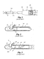
- the cutting instrument 10 includes a handpiece 12 that supports an outer cannula 20.
- a tubular inner cutter 22 is disposed for reciprocation within the outer cannula.
- the cutting head 26 of the inner cutter defines a cutting edge 24 ( FIG. 2 ) that traverses the tissue opening 21 in the outer cannula to sever tissue T.
- An aspiration vacuum A ( FIG. 3 ) draws a vacuum within the tubular inner cutter through aspiration tube 14.
- the reciprocating unit reciprocates the inner cutter 22 in the direction R ( FIG. 2 ) by a drive mount 16 connected to a suitable source of linear motion.
- the outer cannula has an inner diameter D 1 greater than the outer diameter D 2 of the inner cutter. This difference in diameters provides a running clearance for low friction reciprocation of the inner cutter within the outer cutter. In prior reciprocating cutting instruments, this running clearance was maintained through the entire stroke of the inner cutter, including at the tissue opening 21.
- a hinge slot 23 is formed in the inner cutter so that the cutting head 26 can pivot in the direction P ( FIG. 3 ) as the cutting edge 24 contacts the tissue T.
- the tissue tends to resist the forward movement of the cutter. This resistance thus causes the cutting head to pivot in the direction P.
- the cutting head 26 pivots upward, it forms an essentially zero clearance between the cutting edge 24 and the edge of the tissue opening in the outer cannula. This zero clearance allows the inner cutter 22 to cleanly sever the tissue segment T 1 that has been drawn into the outer cannula. On each stroke of the inner cutter 22, new tissue segments T 1 are severed while the vacuum draws previously severed tissue T 2 back through the cutting instrument.
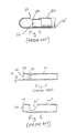
- FIG. 4 Another inner cutter is illustrated in FIG. 4 .
- the hinge slot extends along most of the length of the inner cutter 22' to define a body portion.
- the cutting head pivots in response to the resistance offered by the tissue, and provide an alternative method of securing the inner cutter to the reciprocating unit.
- the cutting head 26 may be "pre-bent” at an angle ⁇ relative to the length of the tubular inner cutter, as shown in FIG. 5 .
- a user then inserts this "pre-bent” inner cutter into the outer cannula when assembling the cutting instrument 10. It has been found that this "pre-bend” characteristic can optimize the cutting performance of the instrument 10 when operating on difficult tissues. For instance, the vitreous tissue of the eye has viscous properties causing it to offer insufficient resistance to the cutting head 26 as the reciprocating unit advances the inner cutter. In the absence of sufficient resistance from the tissue, the cutting head may not pivot fully upward to form the desired zero clearance. In order to ensure a clean and complete cut, the cutting head 26 is bent upward slightly, as shown in FIG.
- a modified inner cutter 22" is shown in FIG. 6 in which the hinge slot 23' is enlarged to optimize the pivot action of the pre-bent cutting head 26.
- the pre-bent cutting head shown in FIGS. 2-6 allows the reciprocating cutting instrument to efficiently sever and aspirate a wide range of tissues, including the troublesome vitreous tissue.
- commercial instruments incorporating the hinged-blade and pre-bend features are capable of cutting speeds that greatly exceed the capabilities of prior tube-within-a-tube cutting instruments.
- the pre-bent cutting head shown in FIGS. 5-6 inherently reduces the running clearance between the outer cannula and the inner reciprocating tubular cutter, making contact between the two components more likely. This contact produces sliding friction that can increase the load upon the drive mechanism used to reciprocate the inner cutter. This increased load manifests itself in a reduction in cutting speed or in the need for a larger drive motor.
- the sliding friction can generate heat along the length of the instrument, which may not be desirable in certain surgical applications. Therefore, further improvement of this successful cutting instrument is always desirable.
- the present invention contemplates a surgical cutting instrument as claimed in claim 1 that includes a cannula with cutting opening through which tissue enters the internal bore of the cannula.
- the cannula bore contains a cutting member with a tubular cutting head sized to prevent the cutting head from exiting cutting opening.
- a source of reciprocating motion reciprocates the cutting member within the cannula past a cutting edge formed on the distal side of the cutting opening.
- a sloped member disposed in the cannula bore guides the cutting head toward the cutting edge as the cutting head advances toward the distal end of the cannula.
- the sloped member enables the cutting head and the cutting edge to form a point of essentially zero clearance, thereby cleanly severing any tissue extending through the cutting opening with a scissor-like action.
- Different slope members are disclosed including a discrete ramp, an indentation, a crease, and an angled distal end of the cannula. Preferred embodiments are disclosed in the dependent claims.
- an improved surgical cutting instrument retains the benefits of the running clearance and the hinged cutting head feature of the cutting instrument shown in FIGS. 1-4 , as well as the benefits of the "pre-bend" feature of the cutting instrument of FIGS. 5-6 .
- the cutting instrument utilizes a outer cannula 40 with a cutting opening 42 and a sloped member to precisely direct the cutting head 26 to an essentially zero clearance point with cutting edge 43 of the cutting opening 42 so that tissue extending into the cannula 40 can be cleanly cut with a scissor-like action.
- the cutting head 26 fully exit the cannula 40 through the cutting opening 42.
- the sloped member contemplates structure that guides the cutting head 26 toward the essentially zero clearance point with the cutting opening 42 including, but not limited to, for example a ramp 60, an indentation 64, a crease 64", or a bend in the distal end of the cannula 40. It is understood that the sloped member may be located within the outer cannula in orientations and positions that urge or guide the cutting head of the inner cannula toward the cutting edge as the cutting head reciprocates toward the distal end of the cannula. Specific embodiments of the present invention are disclosed below.
- FIGS. 7-8 provides an outer cannula 40 with an internal ramp 60 opposing the cutting opening 42. As shown in FIG. 7 , the ramp slopes upward toward the end of the outer cannula 40. The distal end 62 of the ramp is preferably at least coincident with the edge 43 of the opening 42.
- the instrument includes a tubular inner cutter 50 that includes a cutting head with a cutting edge 54 arranged to sever tissue extending through the opening 42.
- the cutter may include a hinge slot 52 so that the cutting head 56 can exhibit the "hinged blade” characteristics of the cutting instrument disclosed in the U.S. Patent WO 5,782,849 .
- the cutting head may be connected to a non-tubular body portion or may be a fully tubular body without the "hinged blade” slot provided that the body is capable of deflecting under influence of the sloped member. In these, as the cutting member advances distally toward the opening 42, the cutting head 56 travels up the ramp 60 toward the edge 43 of the cutting opening.
- the ramp 60 has a height H calibrated in relation to the diameter D l of the inner cutter 50 and the inner diameter D o of the outer cannula 40 so that the cutting edge 54 forms an essentially zero clearance at the edge 43 of the opening.
- the height H of the ramp coincident with the edge 43 of the tissue opening 42 preferably equals the running clearance between the reciprocating inner cutter and the outer cannula 40.
- the height H of the ramp is 0.07 - 0.1 millimetres with a length of 0.25 - 0.3 millimetres.
- the distal end 62 of the ramp is offset distally from the cutting edge 43 of the opening by 0 - 0.05 millimetres.
- the ramp may be selected based on the running clearance between the inner and outer tubes, the size and location of the tissue opening in the outer cannula, the location of the distal end of the ramp 60 relative to the cutting edge and the stroke of the inner cutter.
- the ramp 60 preferably includes a semi-circular cross-section along its length, with the apex aligned with the center of the tissue opening 42.
- Other configurations for the surface of the ramp 60 are contemplated that do not disturb the ability of the inner cutter to slide up the ramp in a stable manner.
- the cutting edge 54 of the inner cutter 50 should be as concentric with the edge 43 of the tissue opening 42 as possible - i.e., the inner cutter should not displace to one side of the outer cannula when the cut is made.
- the surface of the ramp may be slightly concaved at a radius that generally coincides with the diameter D l of the inner cutter.
- it is preferable for the ramp to be disposed diametrically opposite the cutting opening to ensure a precise scissor action between the edge 54 of the cutting head and the cutting edge 43.
- the ramp defines a linear cross-section in that its height increases uniformly along its length to the distal end 62.
- the ramp may define a nonlinear cross section, such as longitudinally concave, provided that it permits smooth sliding movement of the inner cutter along the ramp, without binding.
- the ramp shown in FIG. 7 commences slightly before the proximal edge of the tissue opening. However, the beginning of the ramp may be oriented in a variety of positions relative to the proximal edge of the tissue opening 42.
- the ramp 60 is a separate component from the outer cannula.
- the ramp may be attached in a suitable manner to the inner surface of the outer cannula 40, such as by welding or epoxy.
- a slot (not shown) may be formed in the outer cannula opposite the tissue opening 42 and the ramp may be configured to be mounted within the slot and attached to the outside of the outer cannula.
- the shape of the distal end of the outer cannula 40' defines the ramp 60'.
- an indentation 64 may be formed in the outer It cannula 20 opposite the opening 42.
- a die or punch may form the indentation 64 in a suitable cold-forming process.
- the indentation 64 is formed so that the resulting ramp 60' uniformly increases to the preferred height.
- the indentation could be a circular indentation, a dimple, or a dent so long as when the cutting head 56 contacts the indentation it is guided to a zero clearance position relative the cutting edge 43.
- the entire distal end of the outer cannula may be creased to form a ramp.
- the outer cannula 40" includes a ramp 60" defined by a crease 64" at the distal end of the cannula.
- the crease should be formed at an angle ⁇ calibrated to produce the desired cutting clearance between the cutting edge of the inner cutter and the edge 43 of the tissue opening 42.
- a ramp such as ramps 60, 60' and 60" has been provided on the inner surface of the respective outer cannula so that the inner cutter travels up the ramp to achieve the desired cutting clearance.
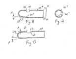
- the distal end 64 of an outer cannula includes a modification to eliminate the ramp while still retaining the ability for an inner tubular cutter to achieve an essentially zero clearance at the edge 63 of the tissue opening 62.
- the distal end is angled relative to the remainder of the outer cannula. The distal end may be bent at an angle ⁇ commencing adjacent the proximal edge 66 of the tissue opening 62.
- the distal edge 63 of the opening is offset at the same angle ⁇ relative to the proximal edge.
- the inner cutter such as the cutter 50 shown in FIG. 7
- the running clearance decreases until the cutting edge 54 reaches an essentially zero clearance at the distal edge 63.
- the cutting head 56 is tubular; however, other configurations are contemplated provided that the portion of the cutting edge 54 cooperating with the cutting edge 43 of the outer cannula is sized to span the width of the opening 42 and is configured to follow the shape of the outer carinula 40, 40', 40" at the opening.
Landscapes
- Health & Medical Sciences (AREA)
- Life Sciences & Earth Sciences (AREA)
- Surgery (AREA)
- Heart & Thoracic Surgery (AREA)
- Engineering & Computer Science (AREA)
- Biomedical Technology (AREA)
- Nuclear Medicine, Radiotherapy & Molecular Imaging (AREA)
- Medical Informatics (AREA)
- Molecular Biology (AREA)
- Animal Behavior & Ethology (AREA)
- General Health & Medical Sciences (AREA)
- Public Health (AREA)
- Veterinary Medicine (AREA)
- Surgical Instruments (AREA)
Applications Claiming Priority (2)
| Application Number | Priority Date | Filing Date | Title |
|---|---|---|---|
| US97165307P | 2007-09-12 | 2007-09-12 | |
| PCT/US2008/076305 WO2009036383A1 (en) | 2007-09-12 | 2008-09-12 | Surgical cutting instrument |
Publications (3)
| Publication Number | Publication Date |
|---|---|
| EP2194892A1 EP2194892A1 (en) | 2010-06-16 |
| EP2194892A4 EP2194892A4 (en) | 2013-08-28 |
| EP2194892B1 true EP2194892B1 (en) | 2015-07-15 |
Family
ID=40432712
Family Applications (1)
| Application Number | Title | Priority Date | Filing Date |
|---|---|---|---|
| EP08829996.1A Not-in-force EP2194892B1 (en) | 2007-09-12 | 2008-09-12 | Surgical cutting instrument |
Country Status (7)
| Country | Link |
|---|---|
| US (1) | US8313501B2 (cg-RX-API-DMAC7.html) |
| EP (1) | EP2194892B1 (cg-RX-API-DMAC7.html) |
| JP (1) | JP5307142B2 (cg-RX-API-DMAC7.html) |
| AU (1) | AU2008298607B2 (cg-RX-API-DMAC7.html) |
| BR (1) | BRPI0816703A2 (cg-RX-API-DMAC7.html) |
| CA (1) | CA2699375C (cg-RX-API-DMAC7.html) |
| WO (1) | WO2009036383A1 (cg-RX-API-DMAC7.html) |
Families Citing this family (20)
| Publication number | Priority date | Publication date | Assignee | Title |
|---|---|---|---|---|
| EP2729098B1 (en) * | 2011-07-08 | 2016-08-17 | Doheny Eye Institute | Ocular lens cutting device |
| US20140100593A1 (en) * | 2012-10-09 | 2014-04-10 | Paul Sand | Plastic Surgical Instruments |
| US9636139B2 (en) * | 2012-12-12 | 2017-05-02 | Covidien Lp | Tissue-removing catheter with ball and socket deployment mechanism |
| US9615969B2 (en) | 2012-12-18 | 2017-04-11 | Novartis Ag | Multi-port vitrectomy probe with dual cutting edges |
| DE102013201784B4 (de) * | 2013-02-04 | 2015-05-28 | Geuder Ag | Vorrichtung zum Schneiden und Absaugen von Gewebe |
| NL2010444C2 (nl) | 2013-03-13 | 2014-09-16 | D O R C Dutch Ophthalmic Res Ct International B V | Oogchirurgisch snijgereedschap. |
| US11547446B2 (en) | 2014-01-13 | 2023-01-10 | Trice Medical, Inc. | Fully integrated, disposable tissue visualization device |
| US9693898B2 (en) * | 2014-11-19 | 2017-07-04 | Novartis Ag | Double-acting vitreous probe with contoured port |
| US10398813B2 (en) * | 2015-02-27 | 2019-09-03 | Marcos Sforza | Harvesting cannula |
| WO2017161177A1 (en) | 2016-03-17 | 2017-09-21 | Trice Medical, Inc. | Clot evacuation and visualization devices and methods of use |
| AU2017236701B2 (en) | 2016-03-24 | 2022-04-07 | Stryker European Operations Holdings Llc | Surgical instrument having cutting assembly with grip |
| US10639197B2 (en) | 2017-06-19 | 2020-05-05 | Alcon Inc. | Vitrectomy probe |
| US11116890B2 (en) * | 2017-08-28 | 2021-09-14 | Surgical Design Corporation | Ocular work tip sleeve adapter |
| US11419971B2 (en) * | 2017-08-28 | 2022-08-23 | Surgical Design Corporation | Ocular surgical work tip adapter |
| WO2019077704A1 (ja) * | 2017-10-18 | 2019-04-25 | 日立ジョンソンコントロールズ空調株式会社 | 弁機構およびこれを備えるスクロール圧縮機 |
| EP3890668A4 (en) * | 2018-12-05 | 2022-08-10 | Medical Instrument Development Laboratories, Inc. | VITRECTOMY PROBE WITH TISSUE MANIPULATION FUNCTION AND METHOD OF MAKING VITRECTOMY PROBE |
| US11826068B2 (en) * | 2018-12-10 | 2023-11-28 | Acclarent, Inc. | Method of forming suction instrument end and shaver instrument end |
| CN113855160A (zh) * | 2021-10-27 | 2021-12-31 | 苏州茵络医疗器械有限公司 | 一种血栓清除设备 |
| USD1026212S1 (en) | 2021-12-13 | 2024-05-07 | Yaniris R. Avellanet | Cannula for removal of fat tissue |
| WO2025101754A1 (en) | 2023-11-09 | 2025-05-15 | Nico Corporation | Flexible instrument adapter for surgical access assembly |
Citations (1)
| Publication number | Priority date | Publication date | Assignee | Title |
|---|---|---|---|---|
| US20050222663A1 (en) * | 2000-12-20 | 2005-10-06 | Fox Hollow Technologies, Inc. | Debulking catheters and methods |
Family Cites Families (13)
| Publication number | Priority date | Publication date | Assignee | Title |
|---|---|---|---|---|
| US3995619A (en) * | 1975-10-14 | 1976-12-07 | Glatzer Stephen G | Combination subcutaneous suture remover, biopsy sampler and syringe |
| US4111207A (en) | 1976-10-28 | 1978-09-05 | David Kopf Instruments | Notched tubular cutting instrument |
| US4552554A (en) * | 1984-06-25 | 1985-11-12 | Medi-Tech Incorporated | Introducing catheter |
| AU6667494A (en) * | 1993-05-07 | 1994-12-12 | Danek Medical, Inc. | Surgical cutting instrument |
| US5360416A (en) * | 1993-09-30 | 1994-11-01 | Sherwood Medical Company | Thin-walled anesthesia needles |
| US5423844A (en) * | 1993-10-22 | 1995-06-13 | Promex, Inc. | Rotary surgical cutting instrument |
| US5800389A (en) * | 1996-02-09 | 1998-09-01 | Emx, Inc. | Biopsy device |
| US6258111B1 (en) * | 1997-10-03 | 2001-07-10 | Scieran Technologies, Inc. | Apparatus and method for performing ophthalmic procedures |
| US6217527B1 (en) * | 1998-09-30 | 2001-04-17 | Lumend, Inc. | Methods and apparatus for crossing vascular occlusions |
| US6638233B2 (en) * | 1999-08-19 | 2003-10-28 | Fox Hollow Technologies, Inc. | Apparatus and methods for material capture and removal |
| IT1316915B1 (it) * | 2000-07-20 | 2003-05-13 | Hs Hospital Service Spa | Dispositivo per biopsia transcutanea di tessuti rigidi. |
| GB2376633B (en) * | 2000-11-06 | 2004-11-10 | Suros Surgical Systems Inc | Biopsy apparatus |
| US6758824B1 (en) * | 2000-11-06 | 2004-07-06 | Suros Surgical Systems, Inc. | Biopsy apparatus |
-
2008
- 2008-09-12 AU AU2008298607A patent/AU2008298607B2/en not_active Ceased
- 2008-09-12 EP EP08829996.1A patent/EP2194892B1/en not_active Not-in-force
- 2008-09-12 JP JP2010525051A patent/JP5307142B2/ja not_active Expired - Fee Related
- 2008-09-12 US US12/210,081 patent/US8313501B2/en active Active
- 2008-09-12 BR BRPI0816703A patent/BRPI0816703A2/pt not_active IP Right Cessation
- 2008-09-12 WO PCT/US2008/076305 patent/WO2009036383A1/en not_active Ceased
- 2008-09-12 CA CA2699375A patent/CA2699375C/en not_active Expired - Fee Related
Patent Citations (1)
| Publication number | Priority date | Publication date | Assignee | Title |
|---|---|---|---|---|
| US20050222663A1 (en) * | 2000-12-20 | 2005-10-06 | Fox Hollow Technologies, Inc. | Debulking catheters and methods |
Also Published As
| Publication number | Publication date |
|---|---|
| BRPI0816703A2 (pt) | 2016-04-05 |
| JP2010538760A (ja) | 2010-12-16 |
| AU2008298607B2 (en) | 2014-01-23 |
| EP2194892A1 (en) | 2010-06-16 |
| CA2699375A1 (en) | 2009-03-19 |
| CA2699375C (en) | 2016-04-19 |
| WO2009036383A1 (en) | 2009-03-19 |
| EP2194892A4 (en) | 2013-08-28 |
| AU2008298607A1 (en) | 2009-03-19 |
| US20090069831A1 (en) | 2009-03-12 |
| US8313501B2 (en) | 2012-11-20 |
| JP5307142B2 (ja) | 2013-10-02 |
Similar Documents
| Publication | Publication Date | Title |
|---|---|---|
| EP2194892B1 (en) | Surgical cutting instrument | |
| US5782849A (en) | Surgical cutting instrument | |
| US5997560A (en) | Surgical cutting instrument | |
| US5733297A (en) | Cutter for surgical probe | |
| AU730317B2 (en) | Endoscopic shaver blade with resilient cutting edges | |
| US5423844A (en) | Rotary surgical cutting instrument | |
| JP6099732B2 (ja) | 対では無い溝を有する外科用バードリル | |
| US9700287B2 (en) | Coaxial incisional full-core biopsy needle | |
| EP1446059B1 (en) | Reciprocating rotary arthroscopic surgical instrument | |
| EP3384857B1 (en) | Surgical cutting instrument with distal suction capability | |
| EP2667803B1 (en) | Surgical cutting instrument with distal suction capability | |
| EP1851013B1 (en) | Improvements in or relating to scissors | |
| US5217479A (en) | Surgical cutting instrument | |
| US8758379B2 (en) | Rotary cutting tool with improved cutting and reduced clogging on soft tissue and thin bone | |
| US5810857A (en) | Surgical knife for controlled lengthening of an incision | |
| US20070106310A1 (en) | Suture cutter | |
| KR20190042566A (ko) | 막힘 감소 팁을 가진 수술 기구용 절개 조립체 | |
| US20050080441A1 (en) | Surgical instruments which are especially useful for ophthalmic surgical procedures, and methods of making the same | |
| US20130110147A1 (en) | Tube set for a rotary tissue cutter with curved inner blade | |
| CN215079099U (zh) | 剪线器 | |
| CN114126469B (zh) | 内置摆动剥离器的内窥镜切除帽 | |
| CN118490291B (zh) | 一种钉仓组件及吻合器 | |
| EP3527152A1 (en) | Tool for a microinvasive surgical instrument and microinvasive surgical instrument | |
| CN112869805A (zh) | 剪线器 | |
| US9414855B1 (en) | Anvil knife for anastomosis tool |
Legal Events
| Date | Code | Title | Description |
|---|---|---|---|
| PUAI | Public reference made under article 153(3) epc to a published international application that has entered the european phase |
Free format text: ORIGINAL CODE: 0009012 |
|
| 17P | Request for examination filed |
Effective date: 20100412 |
|
| AK | Designated contracting states |
Kind code of ref document: A1 Designated state(s): AT BE BG CH CY CZ DE DK EE ES FI FR GB GR HR HU IE IS IT LI LT LU LV MC MT NL NO PL PT RO SE SI SK TR |
|
| AX | Request for extension of the european patent |
Extension state: AL BA MK RS |
|
| DAX | Request for extension of the european patent (deleted) | ||
| RAP1 | Party data changed (applicant data changed or rights of an application transferred) |
Owner name: NICO CORPORATION |
|
| A4 | Supplementary search report drawn up and despatched |
Effective date: 20130726 |
|
| RIC1 | Information provided on ipc code assigned before grant |
Ipc: A61F 9/007 20060101ALI20130722BHEP Ipc: A61B 17/3207 20060101AFI20130722BHEP Ipc: A61B 17/32 20060101ALI20130722BHEP |
|
| 17Q | First examination report despatched |
Effective date: 20140708 |
|
| RAP1 | Party data changed (applicant data changed or rights of an application transferred) |
Owner name: NICO CORPORATION |
|
| GRAP | Despatch of communication of intention to grant a patent |
Free format text: ORIGINAL CODE: EPIDOSNIGR1 |
|
| INTG | Intention to grant announced |
Effective date: 20150306 |
|
| RIC1 | Information provided on ipc code assigned before grant |
Ipc: A61B 17/32 20060101AFI20150220BHEP Ipc: A61F 9/007 20060101ALI20150220BHEP Ipc: A61B 17/3207 20060101ALN20150220BHEP |
|
| GRAS | Grant fee paid |
Free format text: ORIGINAL CODE: EPIDOSNIGR3 |
|
| GRAA | (expected) grant |
Free format text: ORIGINAL CODE: 0009210 |
|
| RIN1 | Information on inventor provided before grant (corrected) |
Inventor name: IRELAND, DANIEL Inventor name: MILLER, SEAN |
|
| AK | Designated contracting states |
Kind code of ref document: B1 Designated state(s): AT BE BG CH CY CZ DE DK EE ES FI FR GB GR HR HU IE IS IT LI LT LU LV MC MT NL NO PL PT RO SE SI SK TR |
|
| REG | Reference to a national code |
Ref country code: CH Ref legal event code: EP Ref country code: GB Ref legal event code: FG4D |
|
| REG | Reference to a national code |
Ref country code: IE Ref legal event code: FG4D |
|
| REG | Reference to a national code |
Ref country code: AT Ref legal event code: REF Ref document number: 736354 Country of ref document: AT Kind code of ref document: T Effective date: 20150815 |
|
| REG | Reference to a national code |
Ref country code: DE Ref legal event code: R096 Ref document number: 602008039054 Country of ref document: DE |
|
| REG | Reference to a national code |
Ref country code: AT Ref legal event code: MK05 Ref document number: 736354 Country of ref document: AT Kind code of ref document: T Effective date: 20150715 |
|
| REG | Reference to a national code |
Ref country code: NL Ref legal event code: MP Effective date: 20150715 |
|
| REG | Reference to a national code |
Ref country code: LT Ref legal event code: MG4D |
|
| PG25 | Lapsed in a contracting state [announced via postgrant information from national office to epo] |
Ref country code: GR Free format text: LAPSE BECAUSE OF FAILURE TO SUBMIT A TRANSLATION OF THE DESCRIPTION OR TO PAY THE FEE WITHIN THE PRESCRIBED TIME-LIMIT Effective date: 20151016 Ref country code: NO Free format text: LAPSE BECAUSE OF FAILURE TO SUBMIT A TRANSLATION OF THE DESCRIPTION OR TO PAY THE FEE WITHIN THE PRESCRIBED TIME-LIMIT Effective date: 20151015 Ref country code: LV Free format text: LAPSE BECAUSE OF FAILURE TO SUBMIT A TRANSLATION OF THE DESCRIPTION OR TO PAY THE FEE WITHIN THE PRESCRIBED TIME-LIMIT Effective date: 20150715 Ref country code: LT Free format text: LAPSE BECAUSE OF FAILURE TO SUBMIT A TRANSLATION OF THE DESCRIPTION OR TO PAY THE FEE WITHIN THE PRESCRIBED TIME-LIMIT Effective date: 20150715 Ref country code: FI Free format text: LAPSE BECAUSE OF FAILURE TO SUBMIT A TRANSLATION OF THE DESCRIPTION OR TO PAY THE FEE WITHIN THE PRESCRIBED TIME-LIMIT Effective date: 20150715 |
|
| PG25 | Lapsed in a contracting state [announced via postgrant information from national office to epo] |
Ref country code: HR Free format text: LAPSE BECAUSE OF FAILURE TO SUBMIT A TRANSLATION OF THE DESCRIPTION OR TO PAY THE FEE WITHIN THE PRESCRIBED TIME-LIMIT Effective date: 20150715 Ref country code: AT Free format text: LAPSE BECAUSE OF FAILURE TO SUBMIT A TRANSLATION OF THE DESCRIPTION OR TO PAY THE FEE WITHIN THE PRESCRIBED TIME-LIMIT Effective date: 20150715 Ref country code: SE Free format text: LAPSE BECAUSE OF FAILURE TO SUBMIT A TRANSLATION OF THE DESCRIPTION OR TO PAY THE FEE WITHIN THE PRESCRIBED TIME-LIMIT Effective date: 20150715 Ref country code: PL Free format text: LAPSE BECAUSE OF FAILURE TO SUBMIT A TRANSLATION OF THE DESCRIPTION OR TO PAY THE FEE WITHIN THE PRESCRIBED TIME-LIMIT Effective date: 20150715 Ref country code: PT Free format text: LAPSE BECAUSE OF FAILURE TO SUBMIT A TRANSLATION OF THE DESCRIPTION OR TO PAY THE FEE WITHIN THE PRESCRIBED TIME-LIMIT Effective date: 20151116 Ref country code: ES Free format text: LAPSE BECAUSE OF FAILURE TO SUBMIT A TRANSLATION OF THE DESCRIPTION OR TO PAY THE FEE WITHIN THE PRESCRIBED TIME-LIMIT Effective date: 20150715 |
|
| REG | Reference to a national code |
Ref country code: DE Ref legal event code: R097 Ref document number: 602008039054 Country of ref document: DE |
|
| PG25 | Lapsed in a contracting state [announced via postgrant information from national office to epo] |
Ref country code: MC Free format text: LAPSE BECAUSE OF FAILURE TO SUBMIT A TRANSLATION OF THE DESCRIPTION OR TO PAY THE FEE WITHIN THE PRESCRIBED TIME-LIMIT Effective date: 20150715 Ref country code: CZ Free format text: LAPSE BECAUSE OF FAILURE TO SUBMIT A TRANSLATION OF THE DESCRIPTION OR TO PAY THE FEE WITHIN THE PRESCRIBED TIME-LIMIT Effective date: 20150715 Ref country code: DK Free format text: LAPSE BECAUSE OF FAILURE TO SUBMIT A TRANSLATION OF THE DESCRIPTION OR TO PAY THE FEE WITHIN THE PRESCRIBED TIME-LIMIT Effective date: 20150715 Ref country code: EE Free format text: LAPSE BECAUSE OF FAILURE TO SUBMIT A TRANSLATION OF THE DESCRIPTION OR TO PAY THE FEE WITHIN THE PRESCRIBED TIME-LIMIT Effective date: 20150715 Ref country code: LU Free format text: LAPSE BECAUSE OF FAILURE TO SUBMIT A TRANSLATION OF THE DESCRIPTION OR TO PAY THE FEE WITHIN THE PRESCRIBED TIME-LIMIT Effective date: 20150912 Ref country code: IT Free format text: LAPSE BECAUSE OF FAILURE TO SUBMIT A TRANSLATION OF THE DESCRIPTION OR TO PAY THE FEE WITHIN THE PRESCRIBED TIME-LIMIT Effective date: 20150715 Ref country code: SK Free format text: LAPSE BECAUSE OF FAILURE TO SUBMIT A TRANSLATION OF THE DESCRIPTION OR TO PAY THE FEE WITHIN THE PRESCRIBED TIME-LIMIT Effective date: 20150715 |
|
| REG | Reference to a national code |
Ref country code: CH Ref legal event code: PL |
|
| PLBE | No opposition filed within time limit |
Free format text: ORIGINAL CODE: 0009261 |
|
| STAA | Information on the status of an ep patent application or granted ep patent |
Free format text: STATUS: NO OPPOSITION FILED WITHIN TIME LIMIT |
|
| PG25 | Lapsed in a contracting state [announced via postgrant information from national office to epo] |
Ref country code: RO Free format text: LAPSE BECAUSE OF FAILURE TO SUBMIT A TRANSLATION OF THE DESCRIPTION OR TO PAY THE FEE WITHIN THE PRESCRIBED TIME-LIMIT Effective date: 20150715 |
|
| 26N | No opposition filed |
Effective date: 20160418 |
|
| REG | Reference to a national code |
Ref country code: IE Ref legal event code: MM4A |
|
| PG25 | Lapsed in a contracting state [announced via postgrant information from national office to epo] |
Ref country code: IS Free format text: LAPSE BECAUSE OF FAILURE TO SUBMIT A TRANSLATION OF THE DESCRIPTION OR TO PAY THE FEE WITHIN THE PRESCRIBED TIME-LIMIT Effective date: 20150715 |
|
| PG25 | Lapsed in a contracting state [announced via postgrant information from national office to epo] |
Ref country code: LI Free format text: LAPSE BECAUSE OF NON-PAYMENT OF DUE FEES Effective date: 20150930 Ref country code: CH Free format text: LAPSE BECAUSE OF NON-PAYMENT OF DUE FEES Effective date: 20150930 Ref country code: IE Free format text: LAPSE BECAUSE OF NON-PAYMENT OF DUE FEES Effective date: 20150912 |
|
| PG25 | Lapsed in a contracting state [announced via postgrant information from national office to epo] |
Ref country code: SI Free format text: LAPSE BECAUSE OF FAILURE TO SUBMIT A TRANSLATION OF THE DESCRIPTION OR TO PAY THE FEE WITHIN THE PRESCRIBED TIME-LIMIT Effective date: 20150715 |
|
| REG | Reference to a national code |
Ref country code: FR Ref legal event code: PLFP Year of fee payment: 9 |
|
| PGFP | Annual fee paid to national office [announced via postgrant information from national office to epo] |
Ref country code: GB Payment date: 20160927 Year of fee payment: 9 |
|
| PGFP | Annual fee paid to national office [announced via postgrant information from national office to epo] |
Ref country code: FR Payment date: 20160926 Year of fee payment: 9 |
|
| PG25 | Lapsed in a contracting state [announced via postgrant information from national office to epo] |
Ref country code: BE Free format text: LAPSE BECAUSE OF FAILURE TO SUBMIT A TRANSLATION OF THE DESCRIPTION OR TO PAY THE FEE WITHIN THE PRESCRIBED TIME-LIMIT Effective date: 20150715 |
|
| PGFP | Annual fee paid to national office [announced via postgrant information from national office to epo] |
Ref country code: DE Payment date: 20160928 Year of fee payment: 9 |
|
| PG25 | Lapsed in a contracting state [announced via postgrant information from national office to epo] |
Ref country code: MT Free format text: LAPSE BECAUSE OF FAILURE TO SUBMIT A TRANSLATION OF THE DESCRIPTION OR TO PAY THE FEE WITHIN THE PRESCRIBED TIME-LIMIT Effective date: 20150715 |
|
| PG25 | Lapsed in a contracting state [announced via postgrant information from national office to epo] |
Ref country code: HU Free format text: LAPSE BECAUSE OF FAILURE TO SUBMIT A TRANSLATION OF THE DESCRIPTION OR TO PAY THE FEE WITHIN THE PRESCRIBED TIME-LIMIT; INVALID AB INITIO Effective date: 20080912 Ref country code: BG Free format text: LAPSE BECAUSE OF FAILURE TO SUBMIT A TRANSLATION OF THE DESCRIPTION OR TO PAY THE FEE WITHIN THE PRESCRIBED TIME-LIMIT Effective date: 20150715 |
|
| PG25 | Lapsed in a contracting state [announced via postgrant information from national office to epo] |
Ref country code: NL Free format text: LAPSE BECAUSE OF FAILURE TO SUBMIT A TRANSLATION OF THE DESCRIPTION OR TO PAY THE FEE WITHIN THE PRESCRIBED TIME-LIMIT Effective date: 20150715 Ref country code: CY Free format text: LAPSE BECAUSE OF FAILURE TO SUBMIT A TRANSLATION OF THE DESCRIPTION OR TO PAY THE FEE WITHIN THE PRESCRIBED TIME-LIMIT Effective date: 20150715 |
|
| PG25 | Lapsed in a contracting state [announced via postgrant information from national office to epo] |
Ref country code: TR Free format text: LAPSE BECAUSE OF FAILURE TO SUBMIT A TRANSLATION OF THE DESCRIPTION OR TO PAY THE FEE WITHIN THE PRESCRIBED TIME-LIMIT Effective date: 20150715 |
|
| REG | Reference to a national code |
Ref country code: DE Ref legal event code: R119 Ref document number: 602008039054 Country of ref document: DE |
|
| GBPC | Gb: european patent ceased through non-payment of renewal fee |
Effective date: 20170912 |
|
| REG | Reference to a national code |
Ref country code: FR Ref legal event code: ST Effective date: 20180531 |
|
| PG25 | Lapsed in a contracting state [announced via postgrant information from national office to epo] |
Ref country code: DE Free format text: LAPSE BECAUSE OF NON-PAYMENT OF DUE FEES Effective date: 20180404 Ref country code: GB Free format text: LAPSE BECAUSE OF NON-PAYMENT OF DUE FEES Effective date: 20170912 |
|
| PG25 | Lapsed in a contracting state [announced via postgrant information from national office to epo] |
Ref country code: FR Free format text: LAPSE BECAUSE OF NON-PAYMENT OF DUE FEES Effective date: 20171002 |
|
| P01 | Opt-out of the competence of the unified patent court (upc) registered |
Effective date: 20230530 |