EP2194857B1 - Outils de criblage de patient pour des systèmes de stimulus cardiaque implantables - Google Patents
Outils de criblage de patient pour des systèmes de stimulus cardiaque implantables Download PDFInfo
- Publication number
- EP2194857B1 EP2194857B1 EP08827799A EP08827799A EP2194857B1 EP 2194857 B1 EP2194857 B1 EP 2194857B1 EP 08827799 A EP08827799 A EP 08827799A EP 08827799 A EP08827799 A EP 08827799A EP 2194857 B1 EP2194857 B1 EP 2194857B1
- Authority
- EP
- European Patent Office
- Prior art keywords
- patient
- icsd
- screening
- screening tool
- shape
- Prior art date
- Legal status (The legal status is an assumption and is not a legal conclusion. Google has not performed a legal analysis and makes no representation as to the accuracy of the status listed.)
- Active
Links
- 230000000747 cardiac effect Effects 0.000 title claims abstract description 31
- 238000012216 screening Methods 0.000 title claims description 121
- 238000004458 analytical method Methods 0.000 claims abstract description 40
- 238000000034 method Methods 0.000 claims description 40
- 238000000718 qrs complex Methods 0.000 claims description 35
- 238000012360 testing method Methods 0.000 claims description 31
- 230000036544 posture Effects 0.000 claims description 24
- 238000001514 detection method Methods 0.000 claims description 19
- 238000007639 printing Methods 0.000 claims description 13
- 238000002513 implantation Methods 0.000 claims description 12
- 210000000038 chest Anatomy 0.000 claims description 2
- 239000007943 implant Substances 0.000 abstract description 15
- 230000006870 function Effects 0.000 abstract description 4
- 230000000007 visual effect Effects 0.000 abstract description 3
- 230000000638 stimulation Effects 0.000 abstract 2
- 238000002565 electrocardiography Methods 0.000 description 57
- 239000013598 vector Substances 0.000 description 29
- 238000007920 subcutaneous administration Methods 0.000 description 15
- 210000001562 sternum Anatomy 0.000 description 8
- 238000012545 processing Methods 0.000 description 5
- 241001433070 Xiphoides Species 0.000 description 4
- 238000004070 electrodeposition Methods 0.000 description 4
- 238000001914 filtration Methods 0.000 description 4
- 230000003278 mimic effect Effects 0.000 description 4
- 238000002560 therapeutic procedure Methods 0.000 description 4
- 210000002417 xiphoid bone Anatomy 0.000 description 4
- 238000013461 design Methods 0.000 description 3
- 238000005259 measurement Methods 0.000 description 3
- 230000001144 postural effect Effects 0.000 description 3
- 230000036279 refractory period Effects 0.000 description 3
- 230000004044 response Effects 0.000 description 3
- 206010003119 arrhythmia Diseases 0.000 description 2
- 230000006793 arrhythmia Effects 0.000 description 2
- 230000008901 benefit Effects 0.000 description 2
- 230000008859 change Effects 0.000 description 2
- 238000004891 communication Methods 0.000 description 2
- 238000013481 data capture Methods 0.000 description 2
- 238000010586 diagram Methods 0.000 description 2
- 210000003205 muscle Anatomy 0.000 description 2
- 230000008569 process Effects 0.000 description 2
- 206010015856 Extrasystoles Diseases 0.000 description 1
- 241001422033 Thestylus Species 0.000 description 1
- 230000003044 adaptive effect Effects 0.000 description 1
- 210000003484 anatomy Anatomy 0.000 description 1
- 210000001099 axilla Anatomy 0.000 description 1
- 238000004364 calculation method Methods 0.000 description 1
- 239000003990 capacitor Substances 0.000 description 1
- 238000004040 coloring Methods 0.000 description 1
- 238000010276 construction Methods 0.000 description 1
- 230000008878 coupling Effects 0.000 description 1
- 238000010168 coupling process Methods 0.000 description 1
- 238000005859 coupling reaction Methods 0.000 description 1
- 238000005520 cutting process Methods 0.000 description 1
- 230000009977 dual effect Effects 0.000 description 1
- 230000000694 effects Effects 0.000 description 1
- 238000002001 electrophysiology Methods 0.000 description 1
- 230000007831 electrophysiology Effects 0.000 description 1
- 210000002837 heart atrium Anatomy 0.000 description 1
- 230000004217 heart function Effects 0.000 description 1
- 230000003211 malignant effect Effects 0.000 description 1
- 239000003550 marker Substances 0.000 description 1
- 238000012986 modification Methods 0.000 description 1
- 230000004048 modification Effects 0.000 description 1
- 230000004118 muscle contraction Effects 0.000 description 1
- 229920003023 plastic Polymers 0.000 description 1
- 239000002985 plastic film Substances 0.000 description 1
- 230000033764 rhythmic process Effects 0.000 description 1
- 210000001991 scapula Anatomy 0.000 description 1
- 238000012106 screening analysis Methods 0.000 description 1
- 230000035945 sensitivity Effects 0.000 description 1
- 238000004513 sizing Methods 0.000 description 1
- 238000003860 storage Methods 0.000 description 1
- 210000005094 subcutaneous system Anatomy 0.000 description 1
- 239000013589 supplement Substances 0.000 description 1
- 238000012549 training Methods 0.000 description 1
- 210000005166 vasculature Anatomy 0.000 description 1
Images


Classifications
-
- A—HUMAN NECESSITIES
- A61—MEDICAL OR VETERINARY SCIENCE; HYGIENE
- A61B—DIAGNOSIS; SURGERY; IDENTIFICATION
- A61B5/00—Measuring for diagnostic purposes; Identification of persons
- A61B5/24—Detecting, measuring or recording bioelectric or biomagnetic signals of the body or parts thereof
- A61B5/316—Modalities, i.e. specific diagnostic methods
- A61B5/318—Heart-related electrical modalities, e.g. electrocardiography [ECG]
- A61B5/321—Accessories or supplementary instruments therefor, e.g. cord hangers
- A61B5/322—Physical templates or devices for measuring ECG waveforms, e.g. electrocardiograph rulers or calipers
-
- A—HUMAN NECESSITIES
- A61—MEDICAL OR VETERINARY SCIENCE; HYGIENE
- A61B—DIAGNOSIS; SURGERY; IDENTIFICATION
- A61B5/00—Measuring for diagnostic purposes; Identification of persons
- A61B5/24—Detecting, measuring or recording bioelectric or biomagnetic signals of the body or parts thereof
- A61B5/316—Modalities, i.e. specific diagnostic methods
- A61B5/318—Heart-related electrical modalities, e.g. electrocardiography [ECG]
- A61B5/333—Recording apparatus specially adapted therefor
- A61B5/338—Recording by printing on paper
-
- A—HUMAN NECESSITIES
- A61—MEDICAL OR VETERINARY SCIENCE; HYGIENE
- A61B—DIAGNOSIS; SURGERY; IDENTIFICATION
- A61B5/00—Measuring for diagnostic purposes; Identification of persons
- A61B5/24—Detecting, measuring or recording bioelectric or biomagnetic signals of the body or parts thereof
- A61B5/316—Modalities, i.e. specific diagnostic methods
- A61B5/318—Heart-related electrical modalities, e.g. electrocardiography [ECG]
- A61B5/346—Analysis of electrocardiograms
-
- A—HUMAN NECESSITIES
- A61—MEDICAL OR VETERINARY SCIENCE; HYGIENE
- A61B—DIAGNOSIS; SURGERY; IDENTIFICATION
- A61B5/00—Measuring for diagnostic purposes; Identification of persons
- A61B5/68—Arrangements of detecting, measuring or recording means, e.g. sensors, in relation to patient
- A61B5/6801—Arrangements of detecting, measuring or recording means, e.g. sensors, in relation to patient specially adapted to be attached to or worn on the body surface
- A61B5/6813—Specially adapted to be attached to a specific body part
- A61B5/6823—Trunk, e.g., chest, back, abdomen, hip
-
- A—HUMAN NECESSITIES
- A61—MEDICAL OR VETERINARY SCIENCE; HYGIENE
- A61B—DIAGNOSIS; SURGERY; IDENTIFICATION
- A61B5/00—Measuring for diagnostic purposes; Identification of persons
- A61B5/74—Details of notification to user or communication with user or patient ; user input means
- A61B5/742—Details of notification to user or communication with user or patient ; user input means using visual displays
-
- A—HUMAN NECESSITIES
- A61—MEDICAL OR VETERINARY SCIENCE; HYGIENE
- A61N—ELECTROTHERAPY; MAGNETOTHERAPY; RADIATION THERAPY; ULTRASOUND THERAPY
- A61N1/00—Electrotherapy; Circuits therefor
- A61N1/18—Applying electric currents by contact electrodes
- A61N1/32—Applying electric currents by contact electrodes alternating or intermittent currents
- A61N1/36—Applying electric currents by contact electrodes alternating or intermittent currents for stimulation
- A61N1/372—Arrangements in connection with the implantation of stimulators
Definitions
- the present invention relates to the field of implantable medical devices. More particularly, the present invention relates to implantable cardiac stimulus devices and methods of determining whether patients are well suited to receive such devices.
- Implantable cardiac stimulus devices can be beneficially used to automatically detect malignant arrhythmias in patient cardiac function and deliver appropriate therapy.
- ICSDs Implantable cardiac stimulus devices
- measurements of ejection fraction coupled with patient history can be used to determine whether a patient may benefit from implantation of an ICSD.
- the next step is to determine which of several ICSD options best suits the patient's needs. Tools for identifying patients who are well suited to certain ICSDs are desired.
- Burri et al. "Utility of the surface ECG before VDD pacemaker implantation", International Journal of Cardiology 117 (2007), p. 211-213 , describes using the maximal P-wave amplitude measured on the surface ECG in order to identify candidates who may be safely implanted with a VDD pacemaker.
- Graphic tools comprising visible indicia for comparison with printed ECG signals are known for example from US 4 550 502 .
- a pre-operative patient screening tool including a stencil designed for comparison to a printed ECG.
- the stencil provides indicia of how a particular ICSD detects cardiac events. Cutaneous electrodes are applied to the patient's skin and ECG signals are captured from the patient using the cutaneous electrodes to generate a printed ECG. The printed ECG is then compared to the stencil by aligning the stencil with the onset of a QRS complex in the printed ECG.
- QRS complex and a portion of the trailing signal fall within the area defined by the stencil, the QRS complex passes, indicating that the patient is likely well suited to the particular ICSD.
- One or several QRS complexes may be tested. Tools or kits for performing such methods are included as further embodiments.
- Figure 1 shows an illustrative patient screening tool
- Figure 2 pictorially illustrates a patient screening method
- Figure 3 shows various canister and electrode positions for subcutaneous implantation of an ICSD
- Figure 4 shows an illustrative shape for a patient screening tool
- Figures 5A-5C illustrate comparisons of a patient screening tool shape to captured cardiac signals
- Figure 6 shows a patient screening tool in the form of a transparency having several shapes thereon
- Figure 7 shows shape comparison for several traces on a single ECG strip
- Figure 8 shows another shape for use in a patient screening tool stencil
- Figure 9 shows a system having shapes for comparison to a printed three-trace ECG strip
- Figure 10 is a block diagram for an illustrative method
- Figure 11 shows another system for capturing data from a patient and providing feedback relating to patient suitability for an ICSD
- Figure 12 shows yet another system for capturing data from a patient and providing feedback relating to patient suitability for an ICSD
- Figure 13 shows another illustrative embodiment allowing a user to select from among several available patient screening tools
- Figure 14 provides details of a working embodiment for a patient screening tool as shown in Figure 1 .
- a practitioner or user may be a physician, a physician's assistant, a medical technician, a nurse, or any other person performing or assisting in performing any method or using any device or system disclosed herein.
- a stencil refers to a visual aid including one or more patterns or shapes used for determining whether a potential implant recipient's cardiac signal is well suited to certain detection methods or devices.
- An illustrative example includes a method for determining whether a particular patient is well suited to receiving a particular ICSD.
- a pre-operative patient screening tool is provided including a stencil designed for comparison to a printed ECG.
- the stencil provides indicia of how a chosen ICSD detects cardiac events.
- cutaneous electrodes are applied to the patient's skin at locations corresponding to implant locations for a set of subcutaneous sensing electrodes that would be used in a particular ICSD.
- ECG signals are captured from the patient using the cutaneous electrodes to generate a printed ECG.
- the surface ECG can be used in this analysis as a surrogate for the subcutaneous ECG.
- the printed ECG is compared to the stencil by aligning an appropriately sized shape in the stencil with the onset of a QRS complex (or, alternatively, some other signal feature such as the R-wave or T-wave peak) in the printed ECG. If the QRS complex and a portion of the trailing signal fall within the shape defined by the stencil, the QRS complex passes, indicating that the patient may be well suited to the particular ICSD. If a portion of the QRS complex and/or trailing signal falls outside the shape, then the electrode pair that generated the QRS complex is found to indicate poor suitability for a given location and patient posture.
- QRS complex or, alternatively, some other signal feature such as the R-wave or T-wave peak
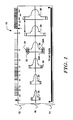
- Figure 1 shows an illustrative example of a patient screening tool 10.
- the patient screening tool 10 may be printed on a transparent plastic sheet, for example.
- the particulars of making the screening tool 10 can vary.
- the patient screening tool 10 includes a rate scale shown at 12.
- the rate scale 12 can be used to estimate the rate of a patient's ongoing cardiac rhythm by aligning a QRS complex from a printed strip with the vertical arrow near the left edge of the rate scale 12 and determining where the second QRS complex to the right of the aligned QRS complex appears on the scale.
- a practitioner is instructed to perform patient screening when the patient's heart rate is in a predefined range, for example, less than 120 beats per minute, and to use a predetermined printing rate (such as 25 mm/sec) for printing the ECG.
- the suggestion to screen at only selected rates may be omitted, if desired.
- a spacing guide is provided as shown at 14.
- the spacing guide 14 can be used to provide indicia for assisting in the correct placement of cutaneous electrodes on the patient to correlate with subcutaneous electrode positions.
- the screening tool is adapted for use with a subcutaneous-only ICSD similar to that shown in Figure 2 .
- a canister 72 is implanted in a lateral pocket and a lead extends medially from the canister 72.
- a lead extends medially from the canister 72.
- electrodes 74, 76, 78 are placed along the left side of the sternum.
- a first sensing electrode 74 is disposed 1 -2 cam above and to the left of the xiphoid of the patient, and a second sensing electrode 76 is disposed about twelve cm above (superior to) the first sensing electrode 74 using incisions placed about fourteen cm apart.
- the spacing guide 14 is shown as a "14 cm Guide" to enable identification first of the incision location, allowing correct placement of the cutaneous electrode near the incision location. Inclusion of a spacing guide 14 is optional.
- the coil electrode 78 may also be used for sensing, if desired, and additional indicia for placing a corresponding cutaneous electrode may be included on the spacing guide 14 as well. If a spacing guide 14 is included, other distances and placements may be used; the 14 cm Guide simply illustrates one embodiment but should not be viewed as limiting.
- the patient screening tool 10 also includes a stencil 16.
- the stencil 16 includes a number of shapes 20, 22, 24, 26, 28, 30 disposed along an alignment line shown across the center of the patient screening tool 10. Though not shown in Figure 1 , in a working example the individual shapes are not only outlined, but each is uniquely colored.
- the shapes 20, 22, 24, 26, 28, 30 are sized such that each can be used for a particular range of ECG amplitudes by providing dashed lines to indicate minimum QRS amplitudes for each shape 20, 22, 24, 26, 28, 30.
- the widest boundaries of shape 24 align with the dashed lines 32 and 32A of shape 26, and the widest boundaries 34 and 34A of shape 26 match the dashed lines for shape 28. If the peak amplitude of an aligned QRS does not fall within spaces between 32 and 34 or between 32A and 34A of shape 26, then shape 26 is not used.
- the dashed lines provide amplitude guidelines for using the shapes 20, 22, 24, 26, 28, 30.
- the shapes 20, 22, 24, 26, 28, 30 do not overlap in the illustrative example.
- the gain setting of the ECG monitor from which an ECG printout is received may be changed. For example, if captured QRS complexes are too big for shape 30, the ECG Recorder/printer gain would be lowered; conversely, if captured QRS complexes are too small for shape 20, the ECG Recorder/printer gain would be raised.
- the patient screening tool 10 may include instructions limiting the applicable gains. In an illustrative example, the user is instructed to use the patient screening tool only within a range of 5-20 mm/mV printed at 25 mm/second. This range may change depending upon the input parameters of the ICSD for which screening is being performed. If amplitude guidelines of the shapes 20, 22, 24, 26, 28, 30 cannot be met using an acceptable ECG gain setting, the patient screening test is failed for the pair of electrodes under consideration.
- a correctly sized shape is compared to the printed ECG when it is aligned with a QRS complex, as shown below in Figures 5A-5C .
- Figure 5A shows a QRS comparison that passes the patient screen
- Figure 5B shows a QRS comparison that fails the patient screen
- Figure 5C shows incorrectly selected shapes.
- a QRS fails if the trace crosses outside an appropriately sized shape 20, 22, 24, 26, 28, 30; otherwise, the QRS passes.
- Whether the patient is found to be well suited to a particular device can be determined by one or several comparisons of QRS complex(es) to the stencil 16.
- multiple measurements are performed by having the patient assume different postures (sitting, standing, supine, etc.) and testing the patient in each. This testing may be performed on one or several available sensing vectors for a particular ICSD.
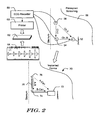
- FIG. 2 illustrates a process including both Preimplant Screening and an Implanted Device, in order to allow comparison of the two.
- Preimplant Screening is shown in which an ECG Recorder 50 is coupled to a cutaneous electrodes 52, 54, 56 that are placed on a patient 58.
- the ECG Recorder 50 is coupled to a printer 60 that is used to create printed ECG strips 62 for comparison to a Patient Screening Tool 64. If the patient 58 passes screening, an Implant procedure is performed.
- the implantation, as completed following passing of the Preimplant Screening, is shown for a subcutaneous ICSD system 70.
- the implanted system 70 is shown with a canister 72 placed along/below the inframammary crease at approximately the left axilla, with a first sensing electrode 74 disposed a few centimeters superior to and left of the xiphoid, with a coil 78 extending along the left side of the sternum about one-to-two centimeters to the left of the midline and a second sensing electrode 76 disposed superior to the coil 78.
- the implanted system 70 thus defines three sensing vectors, shown as A-Can, B-Can and A-B, where "A" indicates electrode 76, "B” indicates electrode 74, and "Can” indicates an electrode disposed on or that is defined as part of the canister 72.
- the cutaneous electrodes 52, 54 and 56 are disposed on the patient 58 during preimplant screening to mimic a set of sensing vectors of the implanted system 70.
- Cutaneous electrode 56 corresponds to implanted electrode 76
- cutaneous electrode 54 corresponds to implanted electrode 74
- cutaneous electrode 52 corresponds to an electrode on the implanted canister 72.
- the ECG Recorder receives a signal from Ch.I that correlates to the A-B sensing vector, a signal from Ch.II that correlates to the A-Can sensing vector, and a signal from Ch.III that correlates to the B-Can sensing vector.
- a standard ECG recorder is used with electrodes RA, LA and LL used as Ch.I, Ch.II and Ch.III, respectively.
- FIG. 2 shows how one configuration of an implanted system may be tested with a patient screening tool 64.
- the patient screening tool 64 is shown in the format shown in Figure 1 .
- the comparison of the patient screening tool 64 to the printed ECGs 62 is further explained below by reference to Figures 5A-5C .
- multiple configurations may be tested, where, if a first configuration fails, a second configuration is tested. For example, if a first set of locations for the cutaneous electrodes 52, 54, 56 leads to a patient screening test failure, different locations for the cutaneous electrodes 52, 54, 56 may be selected, where each set of locations is based on distinct desired locations for different ICSD systems. For example, if the configuration as shown in Figure 2 fails, a different set of locations such as shown in Figure 12 may be tested.
- Figure 3 shows several additional illustrative electrode locations. More than three cutaneous electrodes can be used in order to enable several configurations to be tested at once or for testing of more elaborate systems.
- a different screening tool 64 may be used to test an ICSD having a different cardiac signal analysis configuration.
- the shape shown in Figures 1 and 14 may represent a first configuration for patient screening, while the shape shown in Figure 4 represents a second configuration.
- the configurations may reflect different cardiac signal analysis methods used by different ICSDs and/or different programming choices in a single ICSD.
- a system may have available programming for a first method for use with a patient having a relatively wide QRS complex and, also, programming for a method for use with a patient having a relatively large and/or late T-wave. If a first configuration fails preoperative screening, more configurations may be attempted until preoperative screening is passed, if possible. Variations may also be made in view of different sensing capabilities (such as differences in input circuitry) for different ICSDs.
- a screened configuration for a given patient may receive a grade indicating suitability, and, after screening two or more configurations, the "best" configuration may be selected for use.
- FIG. 2 the patient is shown as having received a subcutaneous-only system 70 having canister 72 and a lead electrode assembly 74, 76, 78. Additional illustrative subcutaneous systems are shown US Patent Numbers 6,647,292. 6,721,597 , and 7,149,575 . Unitary construction or or multiple canisters/leads can be used in other embodiments, as desired.
- the system 70 defines several sensing vectors shown as A-B, A-can and can. Upon implant, one of these sensing vectors may be selected as a default sensing vector. Some illustrative methods for sensing vector selection and/or device initialization are shown in US Patent Application Numbers. US 2007/276445 A , US 2007/276447 A , US 2007/276452 A and US 2008/172100 A . In other embodiments, multi-vector sensing may be performed.
- screening analysis using a screening tool as in Figure 1 is performed with steps for postural analysis as well.
- the patient screening tool is applied to ECG signals captured with the patient in multiple postures to determine device suitability in each posture.
- further analysis may be performed to incorporate postural change data into vector selection.
- postural analysis of an implanted system 70 may be performed as discussed in commonly assigned and copending US Patent Application Number 11/672,353 .
- the canister 72 may house operational circuitry suitable for an implantable cardioverter/defibrillator.
- the operational circuitry may include, for example and without attempting to provide an exhaustive list, suitable memory, logic, analytical hardware, a microcontroller, batteries, antenna(e), charging circuitry, high-power capacitors, input/output circuitry, and telemetry circuitry. It is typical for the system 70 to be adapted to communicate with an external programmer (not shown) via known telemetry methods, to allow various functions to be performed, including device setup, status/history interrogation, new software upload, and/or detection/therapy modification. The details of the system 70 can vary widely.
- Some embodiments may include one or more transvenous leads having electrodes that can be placed and secured within an implantee's vasculature and/or heart or, alternatively, an intrathoracic lead having an epicardial electrode. These epicardial or transvenous leads may supplement or replace the subcutaneous lead shown in Figure 2 .
- a testing method using a stencil and shapes as shown may also be applied to screen patients for a transvenous or epicardial system.
- an appropriate surface model of cardiac signal analysis for a transvenous system can be used to design shapes/stencils for patient screening tools for transvenous systems.
- the specifics of the implanted device and the analytical methods it uses can vary widely.
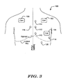
- Figure 3 shows a number of examples of canister and electrode positions for subcutaneous implantation of an ICSD.
- the illustrative systems are shown with canister positions including left pectoral/subclavicular 102, left lateral inframammary 104, and right chest 106.
- canister positions including left pectoral/subclavicular 102, left lateral inframammary 104, and right chest 106.
- electrode positions are shown including left inferior sternum 110 (just above and to the left of the xiphoid), left medial sternum 112 (approximately over the ventricles) and left superior sternum 114 (approximately over or superior to the atria), as well as a right sternum position 116.
- Other positions away from the sternum may be used for placing an electrode, for example, a lateral subpectoral electrode 118.
- posterior positions may be used including positions near the spine or near the scapula. Additional lateral positions may be used as well.
- a subcostal electrode 120 may also be used. Connections to the subcutaneous electrodes are not shown, but it should be understood that the lead(s) would be placed beneath the skin but over the ribs.
- a system is designed for use with several distinct sets of electrode locations.
- preoperative patient screening is used to determine if any combination of the possible electrode locations provides suitable or even superior sensing, in order to determine whether and where the sensing electrodes can be placed.
- the pre-operative patient screening tool of Figure 1 provides a visual reference for performing such screening quickly and easily.
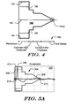
- Figure 4 shows a shape 150 for use in a stencil on an illustrative patient screening tool.
- the illustrative shape 150 includes a baseline marker 152 for alignment with the baseline of a trace on a printed ECG strip.
- the shape 150 is selected such that the maximum deflection for a QRS complex is between a maximum amplitude line 154 and a peak indicator line shown at 156.
- the beginning of a QRS complex is aligned with the left side of the shape 150.
- the widest portion of the shape 150 corresponds to the refractory period of a corresponding ICSD detection method, assuming that the ECG strip to which the shape 150 is compared is printed at a chosen sweep rate.
- the greatest amplitude portion 154 may have a length of 3.5 mm to enable use with ECG strips printed at a sweep rate of 25 millimeters per second. If the ECG falls outside the shape 150 during this first portion ( Figure 5C ), shape 150 has been incorrectly selected and a different size should be chosen, if possible.
- first and second constant threshold time periods occur, as indicated at 160. If the outer border of the shape 150 is crossed by the QRS and its trailing signal (which may include a T-wave, for example), then the screen will be failed. Following the high and mid constant threshold periods, the shape 150 is next defined by a time decay region. If the QRS and its trailing signal crosses the outer border of the shape 150 before it reaches the "Pass" area, which is shown illustratively with a circle in Figure 4 , the screen will be failed.
- the "Pass” area is not narrowly defined, and some discretion may be used along this area. For example, a small crossing in the "Pass” area of shape 150 that appears to be caused by drift may be ignored. Alternatively, if an artifact of the patient's heart signal is identified, then crossing near the "Pass” area may be considered a screening test failure.
- the "Pass” area may be omitted in practice, for example, Figure 1 is based on a working embodiment and lacks this detail.
- Figures 5A-5C illustrate comparisons of a patient screening tool shape to captured cardiac signals.
- trace 200 is printed on ECG strip 202.
- the patient screening tool is placed on the ECG strip 202 such that shape 204 is generally aligned with the baseline of the trace 200.
- the shape 204 may include a line or other indicia for alignment with the baseline of the trace 200.
- the trace 200 is shown as including a peak at 206.
- the shape 204 includes a peak indicator line shown at 208.
- the peak indicator line 208 is included to allow a user to determine that the shape 204 is sized correctly for the trace 200.
- the shape 204 is correctly sized if the peak 206 falls between the outer line 210 and the peak indicator line 208 while the center of the shape 204 is aligned with the baseline of the trace 200. If this is not the case, a larger or smaller shape 204 can be selected from the patient screening tool.
- the shape 204 is matched to the signal amplitude in this fashion to account for the use of an adaptive detection threshold that varies in response to the amplitude of incoming signals. For example, some detection methods use an estimate of peak amplitude to scale the detection thresholds up or down to achieve correct sensing. Thus, selecting a correctly sized patient screening tool accounts for changes in device event detection sensitivity that result from variation in signal amplitude.
- the trace 200 represents an acceptable beat that passes the screening test because it does not cross outside of the border of the shape 204 until the end of the shape 204 as shown at 214.
- the test may be performed once, as shown, or it may be repeatedly performed on a number of captured beats of the trace 200.
- different shapes may be used during this screening if the amplitude of the signal changes.
- a screening failure may be identified if the screening requires use of more than two shapes or use of shapes that are not adjacent in size (referring to Figure 1 , shapes 22 and 24 are "adjacent in size" while shapes 22 and 26 are not). If the trace 200 passes each time it is tested, then the trace 200, and a corresponding sensing vector and patient posture, pass preoperative screening. Several vectors and postures may be tested.
- Figure 5B shows a beat which fails preoperative screening.
- the trace 250 is shown on ECG strip 252.
- a shape 254 from a patient screening tool is placed on the ECG strip 252 relative to the trace 250.
- the shape 254 is aligned with the baseline of the trace 250, and its size is selected such that the QRS peak 256 falls between the peak indicator line 258 and the outer line 260 of the shape 254.
- the analyzed QRS complex includes a large T-wave shown at 262, which extends outside of the shape 254. Because a portion 262 of the trace 250 falls outside of the border of the shape 254, this signal fails to pass the test and may be marked as Poor or Failing.
- any captured event is marked as failing for the trace 250, the trace 250 and associated sensing vector or posture is marked as failing.
- further analysis may be performed in one of two ways.
- further analysis may be performed to determine whether the signal, when analyzed in more detailed fashion, would be difficult to analyze for an ICSD of a particular configuration. This may include analyzing the ratio of the amplitude of the QRS peak to the T-wave peak or analysis of some other signal-to-noise ratio. Other factors such as the timing/spacing of noise may be considered including, for example, the Q-T interval, the QRS width, or whether bigeminy is apparent. For example, further analysis of screening failures may reveal whether a method of identifying erroneous detection can be readily applied to a particular trace 250. This may include analysis using double detection identification methods, for example, as discussed in copending US Provisional Patent Application Number 61/051,332 .
- further analysis may be performed to determine whether the trace 250 consistently fails (i.e. a large percentage of QRS complexes fail). For example, if most QRS complexes fail, the sensing configuration would fail, while if some fail (for example, 5-10% or less), the sensing configuration is acceptable but less than ideal. If multiple configurations are tested, the "best" configuration may be selected.
- Figure 5C shows two examples of incorrectly selected shapes for the given traces.
- the shape on the left is incorrectly selected because the QRS peak falls outside of the widest region of the shape, as shown at 264.
- the shape on the right is incorrectly selected because the QRS peak is not large enough to meet the peak indicator line 266, as shown at 268.
- the illustrative beat analysis shown in Figures 5A-5C may be performed in the clinical and/or ambulatory setting. For example, beats may be analyzed as captured while a patient is in a clinic.
- a patient may receive a Holter monitor to wear for a period of time, and an ECG may be taken from data captured using the Holter monitor and that ECG can be analyzed. Portions of the captured data that are analyzed can be identified by observation of the beat rate for the patient, and events captured during one or both of high and low rate periods may be analyzed using patient screening tools.
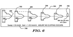
- Figure 6 shows a patient screening tool in the form of a transparency having a stencil with several shapes shown thereon.
- the screening tool 280 is shown as including several shapes 282, 284, 286, 288, 290 thereon.
- the differently sized shapes 282, 284, 286, 288, 290 are provided on the screening tool 280 to allow a practitioner to select the correct size shape for a given ORS complex.
- the screening tool 280 is designed such that the peak indicator 292 of a larger shape 284 matches the maximum amplitude portion 294 of the next smaller shape 286.
- the screening tool 280 is also designed to assist in alignment, with a centered baseline displayed for alignment with the ECG strip.
- Each of the shapes 282, 284, 286, 288, 290 includes a "snub" nose shown at 299. When applied to a QRS, if the ECG trace exits the shape at the "snub" portion 299, this will be considered acceptable; crossing any other line of the shape would constitute a failure.
- the snub nose provides a clear indication of the "Pass" area noted in Figure 4 .
- the border of each shape may be displayed in any suitable fashion, and regions interior to and outside of the border may be differentiated, if so desired, in any suitable fashion, including shading, coloring, opacity, etc.
- the screening tool 280 is shown with an amplitude test shape 296.
- the amplitude test shape 296 indicates the minimum acceptable signal amplitude given defined ECG parameters. Illustrative instructions for sweep and gain used by the ECG recorder and printer are shown at 298. As also indicated at 298, the gain may be adjusted, so long as there is no clipping or cutting off of the peaks of the signal. As indicated, the amplitude test shape 296 is useful when the highest allowed gain setting is applied by the ECG printing device. If a QRS printed at 20 mm/mV is not larger than the amplitude test shape, then the screening test is failed for that QRS.
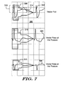
- Figure 7 illustrates comparison to three traces on a single ECG strip.
- the strip 300 includes a first trace shown at 302, a second trace shown at 304, and a third trace shown at 306.
- the first trace 302 is compared to a first shape 308, the second trace 304 is compared to a second shape 310, and the third trace 306 is compared to a third shape 312.
- the shapes 308, 310, 312 are selected to match the greatest magnitude of the respective trace 302, 304, 306. Because each trace 302, 304, 306 varies in printed size, differently sized shapes 308, 310, 312 are chosen for each.
- the first trace 302 fails because portions highlighted at 314 fall outside of the border of the first shape 308.
- the second trace 304 passes because it stays within the border of the second shape 310
- the third trace 306 also passes because it stays within the border of the third shape 312. In this scenario, the second trace 304 and the third trace 306 pass the screening test in the posture.
- Figure 8 shows another shape that may be used in a patient screening tool. Rather than a stepped shape as shown in Figures 5-7 , the shape in Figure 8 indudes smooth contours. Other embodiments may use different shapes as well, for example as shown in Figures 1 and 14 .
- Figures 1 and 14 provide alternatives to that shown in Figure 8 .
- a bullet shape is used instead. This design is adapted to focus the screening tool analysis on the QRS complex and trailing T-wave, which both occur prior to the bullet-shaped portion of these shapes.
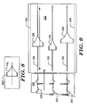
- Figure 9 shows a system having shapes for comparison to a printed three-trace ECG strip.
- the system of Figure 2 illustrates sensing vectors Ch.I, Ch.II, and Ch.III, and would be well suited to printing three traces side-by-side as shown on the strip 320.
- the strip 320 can then be inserted into a comparison tool 322 having guide edges 324 that align the strip 320.
- a shape 326 is slidably secured relative to a track 328 in alignment with the baseline for trace 330. Additional tracks 332, 334 align shapes 336, 338 for comparison to traces 340 and 342.
- the shapes 326, 336, 338 may be snap fit or magnetically secured onto a moveable element in the tracks 328, 332, 334, to allow exchange of different sized shapes 326. It can be seen that the three shapes 326, 336, 338 are each differently sized to accommodate the variation in amplitudes of the signals represented by the three traces 330, 340 and 342.
- the moveable elements for shapes 326, 336, 338 may be configured to increase or decrease in size as they slide to the left or right within tracks 328, 332, 334.
- Other designs for the system may be used, and those of skill in the art will readily recognize that the particulars, including the number of traces used and the manner of controlling comparison of the shapes 326, 336, 338 to the ECG strip may be changed in a number of ways.
- side-by-side stencils each including a number of differently sized shapes may be included in a comparison tool.
- the stencils may be similar to that shown in Figures 1 or 6 , for example.
- An ECG strip would be advanced in the comparison tool until a QRS begins appropriately for a correctly sized shape.
- the stencils can be provided as cut-outs on the cover of the comparison tool 322, enabling a practitioner to mark individual QRS complexes as passing or failing as the strip is passed through the comparison tool 322.
- FIG. 10 is a block diagram for an illustrative method.
- the method 400 begins by setting display and/or printing parameters, as shown at 402.
- a patient screening tool may include directions for sweep and gain that should be used for printing the ECG for use with a screening tool.
- Cutaneous electrodes are placed as indicated at 404.
- the illustrative method next includes having the patient assume a first Posture, as shown at 406. These steps 402, 404, 406 may be performed in any order. Data is captured and one or more Good traces, if any, are identified, as shown at 408. A "Good" trace is one which passes patient screening by comparison of printed ECG data to a patient screening tool.
- any Good traces are again identified, as shown at 412.
- two or more postures selected, for example, from standing, supine, prone, sitting, lying on left or right side, etc.
- the assessment of multiple postures may be skipped in some embodiments, with the method 400 advancing from step 408 directly to block 414.
- data capture may be performed with an ambulatory patient while the patient performs some predetermined activity, such as walking, or, in another method, while the patient is sleeping, by using a Holter monitor to acquire data in a non-clinical setting.
- data from each posture for each vector may be captured, and following completion of data capture, the individual vectors and postures are each analyzed.
- Detailed metric analysis 422 may include numerical analysis of signal-to-noise ratio, overall amplitude, etc. This may include analysis of one or more of the following for at least one cutaneous sensing electrode pair while the patient is in at least one posture:
- a patient who does not pass the pre-implant screen is not further analyzed and instead fails the screening rather than undergoing detailed numerical analysis.
- a patient who fails screening for a given ICSD may be instructed to receive a different device, or may be screened for a different ICSD or different ICSD configuration.
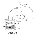
- Figure 11 shows another system, which does not form part of the present inventon, for capturing data from a patient and providing feedback relating to patient suitability for an ICSD.
- a patient 500 is subject to analysis using an external device 502 coupled to external cutaneous electrodes 504, 506, 508, defining vectors A, B and C.
- the position of the cutaneous electrodes 504, 506, 508 is merely illustrative of locations that could be used for the lateral canister, left parasternal lead assembly location as shown above in "Implant" in Figure 2 .
- Other locations may be used in other embodiments, including other anterior positions and/or anterior/posterior combinations such as shown in Figure 3 and/or with implanted transvenous leads in a hybrid system.
- the external device 502 may resemble a personal digital assistant (PDA), for example, and may be a general purpose device running specialized software, or it may be a dedicated device. If desired, the external device 502 may also be a programmer for an implantable device.
- the internal electronics and processing circuitry may include a power supply such as a battery or a circuit for receiving power from a plug-in, in addition to such memory and/or processing circuitry (such as a microprocessor) as may be suitable for performing its functions.
- the external device 502 includes a display screen 510, which may or may not be a touch screen. On the display screen 510 a trace is shown at 512, and, optionally, a comparison shape is shown at 514.
- the shape 514 may be chosen from a menu in order to match amplitude to a captured event, although in some embodiments the shape 514 is automatically sized to match event amplitude by the processing circuitry of the external device 502.
- Showing the shape 514 on the display is optional, as the device 502 may itself perform signal processing to determine suitability of one or more sensing vectors. If internal processing/analysis is performed by the device 502, user input may be requested as a matter of last resort, for example, to resolve uncertainty in the analysis by asking the user to identify QRS complexes.
- Controls shown at 516 may be used to control the display screen 510 and/or analysis.
- buttons P1 and P2 may be used to indicate whether/when the patient 500 has assumed a desired posture and is ready for testing/observation, while buttons A, B, and C may be used to select a channel corresponding to one of the available sensing vectors A, B, C for display or analysis.
- the trace 512 may be shown in real time, or stored data may be shown on the display screen 510.
- the arrow button may be used to move or pause the trace 512 on the display screen 510.
- These buttons are merely illustrative, and less, more, or different buttons may be provided.
- the use of the term "button" should not be construed as limiting to a particular structure; any suitable structure for allowing user input may be used, including a touch screen or a microphone for receiving voice commands.
- the use of the display screen 510 may allow a practitioner to show to the patient 500, for example, how the trace 512 compares to the shape 514.
- the device 502 may have additional outputs for communication (wireless or wired) to a server, computer, additional display, printer, removable storage media, etc.
- the display screen 510 may be used to direct a practitioner and patient through steps of the process, including, for example, directing the practitioner to use predetermined locations for the electrodes 504, 506, 508 and/or directing the practitioner and patient through a series of predetermined postures (sitting, standing, prone, supine, etc.) during data captured and/or analysis.
- the device 502 may perform analysis of the sensing vectors A, B and C and provide an indication to a practitioner of suitability and/or, if desired, which vectors are well suited to use. More than three electrodes may be used, if desired, and placed cutaneously at locations corresponding to locations for implant electrodes, allowing a practitioner to identify and/or select electrode implantation sites. Further, multiple configurations could be tested to identify "best" locations for a given patient.
- the device 502 may include input circuitry that is configured to mimic input characteristics, such as filtering, of an implantable device.
- implantable devices may include various filters that are useful to exclude DC offset and external noise (including myopotentials from patient muscle contractions as well as 50/60 Hz line noise).
- device 502 may include filtering circuits to mimic analog filtering of an implantable device and/or device 502 may include digital filtering circuitry (or may incorporate a digital filter into a microprocessor) to either copy or mimic models of implantable device(s). This may improve the accuracy of measurements with device 502.
- Figure 12 illustrates a device, that does not from part of the present invention, allowing for more detailed analysis by marking signal and/or noise peaks.
- Patient 550 is coupled to a programmer 552 using cutaneous electrodes 554, 556, 558, which are placed for observing signal suitability in a configuration using a pectoral canister location and dual leads (not shown) extending to a left parasternal location and a lateral inframammary location.
- the screening device is shown as a programmer 552, while in other embodiments, a non-programmer external device, which may take any suitable form, may be used instead.
- Three sensing vectors are defined at Ch.I, Ch.II, and Ch.III.
- the programmer 552 allows a practitioner to use one device for each of patient suitability testing, implantation and subsequent follow-up interrogation.
- the illustrative embodiment in Figure 12 illustrates the use of a stylus 564 to identify features of a displayed trace 562 on the touch screen 560.
- a practitioner may perform analysis using the displayed trace 562, rather than manually marking a printed ECG strip.
- analysis of signal-to-noise ratio, noise timing, amplitude, etc. may be performed automatically by the programmer 552.
- This function may also be incorporated into a non-programmer, for example, a device as shown in Figure 11 .
- any suitable number of electrodes 554, 556, 558, may be used, and other locations than those shown may be tested.
- the marking of the ECG trace on the touch screen could also be performed without the patient present, for example, data could be downloaded from a Holter monitor, locally or over the internet or a dedicated system, or data could be captured while the patient is in a clinical setting and then analyzed after the patient is gone or otherwise disconnected from the analysis device. Further, the programmer 552 could itself perform the marking of ORS complexes for the trace 562.
- the programmer 552 can apply a beat detection method that would be used by an implanted device and the practitioner can use the stylus 564 to mark the detected beats as true or false detections.
- the programmer 552 tracks the marking of true and false detections and determines whether the beat detection method in combination with the locations of the electrodes 554, 556, 558 results in suitable cardiac signal analysis.
- wireless coupling may be provided for this analysis.
- FIG 13 illustrates another embodiment in which several differently sized patient screening tool shapes are available.
- the tool 600 includes several strips 602, 604, 606, 608 that can be moved about an axis 610 to allow one of the strips 602, 604, 606, 608 to be selected. As indicated, each strip 602, 604, 606, 608 provides instructions to a user for the proper setting of ECG printout or display equipment.
- the illustrative tool 600 is configured with clear stencit/shape regions surrounded by a patterned field.
- the illustrative tool 600 is shown as being packaged in a kit 620 along with instructions 622. Similar kits 620 may be use to provide any of the illustrative embodiments of patient screening tools (such as in Figures 1 , 2 , 6 , 9 and 13 ) and/or devices (such as in Figures 11-12 ). Alternatively the patient screening tool 600 may be provided as part of a larger kit for an overall system, or may simply be provided to practitioners with training and reminders on the tool itself, as in Figure 1 .
- This embodiment was designed for use with a subcutaneous-only ICSD having an input voltage range of up to 3.6 millivolts, with a noise floor estimated in the range of about 80 microvolts. Based on a selected 3X signal to noise floor ratio, the smallest allowable peak amplitude was set at 0.25 millivolts.
- a screening tool having the six shapes 20, 22, 24, 26, 28, 30 of Figure 1 was selected. These shapes were sized as shown in Figure 14 . Timing features were as shown at the reference shape 40. The times are translated into actual lengths in table 42, which indicates the sizing is set up for use at a 25 mm/S sweep rate. The dimensions for references W, X, Y and Z are shown in millimeters in table 44.
- the allowed gains for ECG printing were set to 5-20 mm/mV.
- the largest amplitude would be found using the largest "W" value and dividing by the smallest gain.
- W the largest amplitude
- 3.5 millivolts was the largest QRS that would be allowed. This leaves a margin of 0.1 millivolts to prevent clipping by the implant.
- the smallest amplitude would be found using the smallest X value (the amplitude minimum) divided by the largest gain.
- the smallest input would be at 0.25 millivolts.
- the numbers are designed to allow full coverage of a major portion of the available dynamic input range of a corresponding ICSD.
- the example shown does not call for overlap of the stencil shapes. If desired, some overlap may be allowed by letting the peak indicator lines overlap the outermost edges of adjacent shapes.
- peak indicator lines 32. 32A could correspond to a smaller amplitude than the maximum amplitude for shape 24, while maximum amplitude 34 of shape 26 could be wider than the peak indicator lines on shape 28.
- a cutaneous testing system may be used to analyze or debug device operation after an implantation is complete. For example, following implantation, cutaneous testing may be performed by placing cutaneous electrodes at locations corresponding to subcutaneous electrode locations of an implanted device. The detection characteristics of the implanted system may be compared to signals observed or generated cutaneously to identify sensing flaws in an implanted system. In particular, lead failures may be diagnosed by this method/system, although other problems with input or detection circuitry or methods, for example, may also be analyzed.
- At least one of the cutaneous electrodes may double as, or may be attached using a lead that incorporates an antenna for communication with the implanted system.
- One or more cutaneous electrodes may also incorporate a magnet for disabling therapy response of the implanted system during the external analysis.
- shape comparisons may also be based upon intracardiac or intravascular data.
- data may be gathered during an electrophysiology study.
- Data may also be captured from an implanted device having transvenous and/or epicardial electrodes, for example, using data relayed via telemetry to an external device.
- the shape comparison may also be performed to determine suitability of a hybrid device having subcutaneous and/or intravascular or intracardiac electrodes.
- one patient screening tool may integrate shapes adapted to each of several cardiac signal analysis methods.
- the shape may include different semi-transparent regions of color, for example, visually indicating whether one or more of these features are identified in the trace.
- the patient screening tool may be used to identify whether any of several available detection methods for a particular ICSD would be suitable.
Claims (17)
- Procédé pour l'examen d' un patient pour lequel on dispose d'indications concernant le fait qu'il puisse bénéficier d'un dispositif implantable procurant une stimulation cardiaque (ICSD) comprenant le fait de :procurer un instrument pour l'examen d'un patient (10 , 64 , 280 , 600) comprenant un stencil (16) conçu pour une comparaison à un ECG imprimé, le stencil (16) procurant des premiers repères visibles (20 , 22 , 24 , 26 , 28 , 30 , 40 , 150 , 204 , 254 , 282 , 284 , 286 , 288 , 290 , 308 , 310 , 312) de la façon dont un ICSD particulier détecte des événements cardiaques, les premiers repères visibles (20 , 22 , 24 , 26 , 28 , 30 , 40 , 150 , 204 , 254 , 282 , 284 , 286 , 288 , 290 , 308 , 310 , 312) étant adaptés pour identifier des individus qui sont bien appropriés pour bénéficier d'un ICSD possédant une première configuration ;placer plusieurs électrodes cutanées (52 , 54 , 56) sur la peau du patient à des premiers endroits correspondants à des endroits d'implantation planifiés pour des électrodes d'un ICSD possédant une première configuration ;enregistrer et imprimer des signaux ECG en utilisant les électrodes cutanées (52 , 54 , 56) placées en premier lieu ;comparer à l'oeil nu les signaux ECG imprimés aux premiers repères visibles (20 , 22 , 24 , 26 , 28 , 30, 40, 150, 204, 254, 282 , 284, 286 , 288 , 290 , 308 , 310 , 312) de l'instrument pour l'examen d'un patient (10 , 64 , 280 , 600); etlorsque les signaux ECG imprimés rencontrent les critères d'examen de l'instrument pour l'examen d'un patient (10 , 64 , 280 , 600), déterminer le fait que le patient est bien approprié pour bénéficier d'un ICSD possédant une première configuration ; ousi tel n'est pas le cas, déterminer que le patient ne doit pas bénéficier de l'ICSD possédant une première configuration.
- Procédé selon la revendication 1, dans lequel l'étape de comparaison à l'oeil nu est mise en oeuvre sous la forme d'un test de dépistage comprenant le fait de :identifier un complexe QRS dans le ECG imprimé ;sélectionner, à partir de plusieurs configurations disponibles dans les premiers repères visibles (20 , 22 , 24 , 26 , 28 , 30 , 40 , 150 , 204 , 254 , 282 , 284 , 286 , 288 , 290 , 308, 310 , 312), une configuration possédant une mesure d'amplitude correcte pour le complexe QRS identifié ;mettre la configuration sélectionnée en alignement avec le complexe QRS identifié ;examiner le complexe QRS pour voir s'il déborde ou non à l'extérieur (262 , 314) de la configuration sélectionnée d'une manière qui correspondrait à une détection erronée par un ICSD ; etdans le cas où l'on ne constate aucun débordement à l'extérieur (262 , 314) de la configuration sélectionnée, déterminer que le complexe QRS réussit le test de dépistage ; oudans le cas où l'on constate un débordement à l'extérieur (262 , 314) de la configuration sélectionnée, déterminer que le complexe QRS ne réussit pas le test de dépistage.
- Procédé selon la revendication 2, dans lequel le test de dépistage est mis en oeuvre sur plusieurs complexes QRS et, dans le cas où chaque complexe QRS testé réussit le test, l'ECG imprimé est considéré comme une indication que le patient est bien approprié pour bénéficier de l'ICSD possédant la première configuration.
- Procédé selon la revendication 2, dans lequel les premiers repères visibles (20 , 22 , 24, 26 , 28 , 30 , 40 , 150 , 204 , 254 , 282 , 284 , 286 , 288 , 290 , 308, 310 , 312) englobent un indicateur d'amplitude (32 , 156 , 208 , 258 , 266) associé à chaque configuration.
- Procédé selon la revendication 1, dans lequel on prévoit plusieurs emplacements d'implantation planifiés par voie sous-cutanée en dessous de la peau du patient et par-dessus la cage thoracique du patient.
- Procédé selon la revendication 5, dans lequel, dans le cas où l'on détermine que le patient ne doit pas bénéficier du ICSD possédant une première configuration, le procédé comprend en outre le fait de placer au moins une desdites plusieurs électrodes cutanées (52 , 54 , 56) à un ou plusieurs deuxièmes endroits sur la peau du patient correspondants à un ICSD possédant une deuxième configuration, et répéter les étapes d'enregistrement/impression et de comparaison à l'oeil nu afin de déterminer le fait de savoir si le patient est bien approprié pour bénéficier d'un ICSD possédant une deuxième configuration.
- Procédé selon la revendication 5, dans lequel dans le cas où l'on détermine que le patient ne doit pas bénéficier du ICSD possédant une première configuration, le procédé comprend en outre le fait de procurer un deuxième instrument pour l'examen d'un patient adapté pour identifier des individus qui sont bien appropriés pour bénéficier d'un ICSD possédant une deuxième configuration, et le fait de répéter l'étape de comparaison à l'oeil nu, cette fois-ci en utilisant le deuxième instrument pour l'examen d'un patient, tout en laissant les électrodes cutanées (52 , 54 , 56) aux premiers endroits.
- Procédé selon la revendication 1, dans lequel l'instrument pour l'examen d'un patient (10 , 64 , 280 , 600) comprend plusieurs configurations (20 , 22 , 24 , 26 , 28 , 30 , 40 , 150 , 204 , 254 , 282 , 284 , 286 , 288 , 290 , 308, 310 , 312) configurées pour correspondre à au moins une certaine portion d'un profil de détection d'événement cardiaque utilisé par le ICSD possédant une première configuration pour détecter des événements cardiaques.
- Procédé selon la revendication 8, dans lequel lesdites plusieurs configurations (20 , 22 , 24 , 26 , 28 , 30 , 40 , 150 , 204 , 254 , 282 , 284 , 286 , 288 , 290 , 308 , 310, 312) de l'instrument pour l'examen d'un patient (10 , 64 , 280 , 600) sont dimensionnées pour correspondre à plusieurs plages d'amplitudes de signaux enregistrés possibles de telle sorte que, pour un complexe QRS reçu particulier dans le ECG imprimé, une seule configuration peut être identifiée pour l'emploi.
- Procédé selon la revendication 8, dans lequel l'instrument pour l'examen d'un patient (10 , 64 , 280) englobe un champ transparent sur lequel sont disposées les configurations (20 , 22 , 24 , 26 , 28 , 30 , 40 , 150 , 204 , 254 , 282, 284 , 286 , 288 , 290 , 308 , 310 , 312) d'une manière qui permet à l'instrument pour l'examen d'un patient (10 , 64 , 280) de venir se placer par-dessus l'ECG imprimé à des fins de comparaison à ce dernier.
- Procédé selon la revendication 8, dans lequel l'instrument pour l'examen d'un patient (600) englobe des régions transparentes correspondant à des configurations individuelles, permettant à une configuration sélectionnée de venir se placer par-dessus l'ECG imprimé à des fins de comparaison à ce dernier.
- Procédé selon la revendication 8, dans lequel l'instrument pour l'examen d'un patient (10) comprend en outre des repères (14) d'espacements corrects pour le placement des électrodes cutanées (52 , 54 , 56).
- Procédé selon la revendication 1, dans lequel l'étape consistant à enregistrer et à imprimer des signaux ECG en utilisant les électrodes cutanées placées en premier lieu est mise en oeuvre alors que le patient se trouve dans chacune des première et deuxième postures, respectivement, et l'étape consistant à comparer à l'oeil nu les signaux ECG imprimé aux premiers repères visibles (20 , 22 , 24 , 26 , 28, 30 , 40 , 150 , 204 , 254 , 282 , 284 , 286 , 288 , 290 , 308 , 310 , 312) de l'instrument pour l'examen d'un patient (10 , 64 , 280 , 600) englobe la comparaison de signaux ECG imprimés enregistrés lorsque le patient prend chacune d'au moins lesdites première et deuxième postures.
- Instrument pour l'examen d'un patient (10 , 64 , 280) comprenant une feuille transparente de matière sur laquelle est imprimé un stencil de dépistage (16), le stencil de dépistage (16) englobant des repères visibles comprenant plusieurs configurations individuelles (20 , 22, 24 , 26 , 28 , 30 , 40 , 150 , 204 , 254 , 282 , 284 , 286 , 288 , 290 , 308 , 310 , 312) visibles sur la feuille transparente, le stencil de dépistage (16) étant configuré pour une utilisation avec un dispositif implantable procurant une stimulation cardiaque (ICSD) de configuration particulière possédant une gamme de tensions d'entrée et utilisant une analyse de détection d'événement cardiaque prédéterminée, les configurations (20 , 22 , 24, 26 , 28 , 30 , 40 , 150 , 204 , 254 , 282 , 284 , 286 , 288 , 290 , 308 , 310 , 312) possédant des attributs dimensionnels permettant de couvrir complètement une portion majeure de la plage d'entrées dynamiques disponibles du ICSD de configuration particulière et indiquant la façon dont le ICSD de configuration particulière détecte des événements cardiaques,
dans lequel l'instrument pour l'examen d'un patient (10 , 64 , 280) est dimensionné de façon à permettre des comparaisons à des données ECG imprimées enregistrées à partir d'un receveur potentiel de l'ICSD de configuration particulière, dans le cadre de directives d'impression prédéterminées y compris le gain d'amplitude et la vitesse de balayage lors de l'impression (298). - Nécessaire (620) à utiliser dans le cadre de l'examen d'un patient à un stade préopératoire pour un dispositif implantable procurant des stimulations cardiaques (ICSD), comprenant :un premier instrument pour l'examen d'un patient (10 , 64 , 280 , 600) englobant un premier stencil (16) conçu pour une comparaison à un tracé ECG imprimé, le premier stencil procurant des premiers repères visibles (20, 22 , 24 , 26 , 28 , 30 , 40 , 150 , 204 , 254 , 282 , 284 , 286 , 288 , 290 , 308 , 310 , 312) quant à la façon dont un ICSD particulier détecte des événements cardiaques, etdes instructions (622) pour l'utilisation de l'instrument pour l'examen d'un patient (10 , 64 , 280 , 600), de la manière indiquée ci-après consistant à :placer plusieurs électrodes cutanées (52, 54 , 56) sur la peau du patient à des premiers endroits correspondants à des endroits d'implantation planifiés pour des électrodes du ICSD possédant une première configuration ;enregistrer et imprimer des signaux ECG en utilisant les électrodes cutanées (52 , 54 , 56) placées ;procéder à une comparaison à l'oeil nu entre les signaux ECG imprimés et les premiers repères visibles (20 , 22 , 24 , 26 , 28 , 30 , 40 , 150 , 204 , 254, 282 , 284 , 286 , 288 , 290 , 308 , 310 , 312) ; etlorsque les signaux ECG imprimés rencontrent les critères d'examen du premier instrument pour l'examen d'un patient (10 , 64 , 280 , 600), déterminer le fait que le patient est bien approprié pour bénéficier du ICSD possédant une première configuration ; ousi tel n'est pas le cas, déterminer que le patient ne doit pas bénéficier de l'ICSD possédant une première configuration.
- Nécessaire selon la revendication 15, comprenant en outre au moins un deuxième instrument pour l'examen d'un patient possédant un deuxième stencil conçu pour une comparaison à un tracé ECG imprimé, le deuxième stencil procurant des deuxièmes repères visibles de la façon dont un ICSD particulier possédant une deuxième configuration détecte des événements cardiaques.
- Nécessaire selon la revendication 15, dans lequel les instructions englobent des deuxièmes endroits pour le placement desdites plusieurs électrodes cutanées (52 , 54 , 56) lorsqu'on détermine que le patient ne doit pas bénéficier du ICSD de première configuration.
Applications Claiming Priority (3)
| Application Number | Priority Date | Filing Date | Title |
|---|---|---|---|
| US95745607P | 2007-08-23 | 2007-08-23 | |
| PCT/US2008/074118 WO2009026571A2 (fr) | 2007-08-23 | 2008-08-22 | Outils de criblage de patient pour des systèmes de stimulus cardiaque implantables |
| US12/196,779 US8079959B2 (en) | 2007-08-23 | 2008-08-22 | Patient screening tools for implantable cardiac stimulus systems |
Publications (2)
| Publication Number | Publication Date |
|---|---|
| EP2194857A2 EP2194857A2 (fr) | 2010-06-16 |
| EP2194857B1 true EP2194857B1 (fr) | 2011-11-30 |
Family
ID=39855157
Family Applications (1)
| Application Number | Title | Priority Date | Filing Date |
|---|---|---|---|
| EP08827799A Active EP2194857B1 (fr) | 2007-08-23 | 2008-08-22 | Outils de criblage de patient pour des systèmes de stimulus cardiaque implantables |
Country Status (9)
| Country | Link |
|---|---|
| US (3) | US8079959B2 (fr) |
| EP (1) | EP2194857B1 (fr) |
| JP (1) | JP5308443B2 (fr) |
| CN (1) | CN101861122B (fr) |
| AT (1) | ATE535187T1 (fr) |
| AU (1) | AU2008288728B2 (fr) |
| CA (1) | CA2695468C (fr) |
| ES (1) | ES2377250T3 (fr) |
| WO (1) | WO2009026571A2 (fr) |
Families Citing this family (37)
| Publication number | Priority date | Publication date | Assignee | Title |
|---|---|---|---|---|
| JP5308443B2 (ja) | 2007-08-23 | 2013-10-09 | キャメロン ヘルス、 インコーポレイテッド | 込心臓刺激システム用の患者スクリーニングキットおよび患者スクリーニング装置 |
| WO2009092055A1 (fr) | 2008-01-18 | 2009-07-23 | Cameron Health, Inc. | Manipulation de données après l'administration d'une stimulation cardiaque dans un dispositif de stimulation cardiaque implantable |
| EP2268357B1 (fr) | 2008-03-07 | 2016-11-02 | Cameron Health, Inc. | Dispositifs permettant de classer avec précision l activité cardiaque |
| CA2717442C (fr) | 2008-03-07 | 2017-11-07 | Cameron Health, Inc. | Detection d'evenement cardiaque aigu dans un dispositif de stimulation cardiaque implantable |
| WO2009137726A2 (fr) | 2008-05-07 | 2009-11-12 | Cameron Health, Inc. | Procédés et dispositifs permettant une classification précise de l’activité cardiaque |
| WO2010068934A1 (fr) | 2008-12-12 | 2010-06-17 | Cameron Health, Inc. | Systèmes de défibrillateurs implantables et procédé d'atténuation évitant la saturation et mise en place |
| WO2011008550A1 (fr) | 2009-06-29 | 2011-01-20 | Cameron Health, Inc. | Confirmation adaptative d'une arythmie traitable dans des dispositifs de stimulation cardiaque implantables |
| US8265737B2 (en) | 2009-10-27 | 2012-09-11 | Cameron Health, Inc. | Methods and devices for identifying overdetection of cardiac signals |
| US8744555B2 (en) | 2009-10-27 | 2014-06-03 | Cameron Health, Inc. | Adaptive waveform appraisal in an implantable cardiac system |
| EP2359742B1 (fr) * | 2009-11-19 | 2013-07-17 | Olympus Medical Systems Corp. | Système de dispositif médical, système de dispositif médical à capsule, et procédé pour afficher des éléments de posture d'un corps à tester |
| US8548573B2 (en) | 2010-01-18 | 2013-10-01 | Cameron Health, Inc. | Dynamically filtered beat detection in an implantable cardiac device |
| US8588895B2 (en) | 2011-04-22 | 2013-11-19 | Cameron Health, Inc. | Robust rate calculation in an implantable cardiac stimulus or monitoring device |
| US9849291B2 (en) | 2011-06-09 | 2017-12-26 | Cameron Health, Inc. | Antitachycardia pacing pulse from a subcutaneous defibrillator |
| EP2967404B1 (fr) | 2013-03-11 | 2019-05-22 | Cameron Health, Inc. | Dispositif d'implémentation de critères doubles pour la détection des arythmies |
| US9486637B2 (en) | 2014-07-24 | 2016-11-08 | Medtronic, Inc. | Method and apparatus for accurate separation of supraventricular tachycardia from ventricular tachycardia during posture changes |
| US9924885B2 (en) | 2014-07-24 | 2018-03-27 | Medtronic, Inc. | Rhythm discriminator with immunity to body posture |
| US9554714B2 (en) | 2014-08-14 | 2017-01-31 | Cameron Health Inc. | Use of detection profiles in an implantable medical device |
| US10188867B2 (en) * | 2015-01-23 | 2019-01-29 | Medtronic, Inc. | Method and apparatus for beat acquisition during template generation in a medical device having dual sensing vectors |
| US9993171B2 (en) * | 2015-04-08 | 2018-06-12 | Cameron Health, Inc. | Automated screening methods and apparatuses for implantable medical devices |
| IL254305B2 (en) * | 2015-06-22 | 2023-03-01 | D Heart S R L | Electrical system for controlling electrocardiogram measurement |
| US10321834B2 (en) | 2015-10-23 | 2019-06-18 | Cardiac Pacemakers, Inc. | Multi-vector sensing in cardiac devices using a hybrid approach |
| US10391325B2 (en) | 2016-05-04 | 2019-08-27 | Cardiac Pacemakers, Inc. | Electrode designs in implantable defibrillator systems |
| JP6764956B2 (ja) | 2016-06-27 | 2020-10-07 | カーディアック ペースメイカーズ, インコーポレイテッド | 再同期ペーシング管理に皮下で感知されたp波を使用する心臓治療法システム |
| US10426962B2 (en) | 2016-07-07 | 2019-10-01 | Cardiac Pacemakers, Inc. | Leadless pacemaker using pressure measurements for pacing capture verification |
| WO2018039335A1 (fr) | 2016-08-24 | 2018-03-01 | Cardiac Pacemakers, Inc. | Thérapie intégrée de resynchronisation cardiaque à dispositifs multiples utilisant l'onde p pour stimuler la synchronisation. |
| EP3503970B1 (fr) | 2016-08-24 | 2023-01-04 | Cardiac Pacemakers, Inc. | Resynchronisation cardiaque utilisant l'encouragement de la fusion pour la gestion de la synchronisation |
| US10758737B2 (en) | 2016-09-21 | 2020-09-01 | Cardiac Pacemakers, Inc. | Using sensor data from an intracardially implanted medical device to influence operation of an extracardially implantable cardioverter |
| WO2018081275A1 (fr) | 2016-10-27 | 2018-05-03 | Cardiac Pacemakers, Inc. | Thérapie de resynchronisation cardiaque à dispositifs multiples avec des améliorations de synchronisation |
| US10765871B2 (en) | 2016-10-27 | 2020-09-08 | Cardiac Pacemakers, Inc. | Implantable medical device with pressure sensor |
| US11235145B2 (en) | 2016-11-17 | 2022-02-01 | Cardiac Pacemakers, Inc. | Directional subcutaneous implantable cardioverter defibrillator electrode |
| EP3541471B1 (fr) | 2016-11-21 | 2021-01-20 | Cardiac Pacemakers, Inc. | Stimulateur cardiaque sans sonde fournissant un traitement de resynchronisation cardiaque |
| WO2018118818A1 (fr) | 2016-12-21 | 2018-06-28 | Cardiac Pacemakers, Inc. | Dérivation à électrodes intégrées |
| US11207532B2 (en) | 2017-01-04 | 2021-12-28 | Cardiac Pacemakers, Inc. | Dynamic sensing updates using postural input in a multiple device cardiac rhythm management system |
| EP3668592B1 (fr) | 2017-08-18 | 2021-11-17 | Cardiac Pacemakers, Inc. | Dispositif médical implantable avec capteur de pression |
| CN110477906B (zh) * | 2019-08-26 | 2021-11-26 | 电子科技大学 | 一种心电信号qrs波起止点定位方法 |
| US20210169359A1 (en) * | 2019-12-06 | 2021-06-10 | Biosense Webster (Israel) Ltd. | Intra-cardiac pattern matching |
| CN116392717B (zh) * | 2023-06-07 | 2023-08-25 | 苏州维伟思医疗科技有限公司 | 体外除颤系统、装置及其放电方法 |
Family Cites Families (32)
| Publication number | Priority date | Publication date | Assignee | Title |
|---|---|---|---|---|
| US4030486A (en) * | 1969-06-10 | 1977-06-21 | George Eastman | Apparatus for measuring deflection and temporal values on electrocardiac tracings |
| US3980362A (en) * | 1974-08-28 | 1976-09-14 | Harter B Wayne | Position finding and course determining instrument |
| JPS5613928Y2 (fr) * | 1974-12-28 | 1981-04-01 | ||
| US4550502A (en) * | 1983-04-15 | 1985-11-05 | Joseph Grayzel | Device for analysis of recorded electrocardiogram |
| US4884345A (en) * | 1988-05-12 | 1989-12-05 | Siemens-Pacesetter, Inc. | Adjustable template for pacemaker ECG analysis and method of use |
| US5137025A (en) * | 1990-12-17 | 1992-08-11 | Turner Ii Henry H | Nomogram for electrocardiographic interpretation and method of use |
| US6496715B1 (en) * | 1996-07-11 | 2002-12-17 | Medtronic, Inc. | System and method for non-invasive determination of optimal orientation of an implantable sensing device |
| WO1998002209A2 (fr) * | 1996-07-11 | 1998-01-22 | Medtronic, Inc. | Dispositif implantable peu invasif permettant de surveiller des evenements physiologiques |
| US6470893B1 (en) * | 2000-05-15 | 2002-10-29 | Peter V. Boesen | Wireless biopotential sensing device and method with capability of short-range radio frequency transmission and reception |
| US6721597B1 (en) * | 2000-09-18 | 2004-04-13 | Cameron Health, Inc. | Subcutaneous only implantable cardioverter defibrillator and optional pacer |
| US7149575B2 (en) * | 2000-09-18 | 2006-12-12 | Cameron Health, Inc. | Subcutaneous cardiac stimulator device having an anteriorly positioned electrode |
| US6647292B1 (en) * | 2000-09-18 | 2003-11-11 | Cameron Health | Unitary subcutaneous only implantable cardioverter-defibrillator and optional pacer |
| AU2002240363A1 (en) * | 2001-02-13 | 2002-08-28 | Quetzal Biomedical, Inc. | Multi-electrode apparatus and method for treatment of congestive heart failure |
| US6892092B2 (en) * | 2001-10-29 | 2005-05-10 | Cardiac Pacemakers, Inc. | Cardiac rhythm management system with noise detector utilizing a hysteresis providing threshold |
| US7248921B2 (en) * | 2003-06-02 | 2007-07-24 | Cameron Health, Inc. | Method and devices for performing cardiac waveform appraisal |
| US7330757B2 (en) * | 2001-11-21 | 2008-02-12 | Cameron Health, Inc. | Method for discriminating between ventricular and supraventricular arrhythmias |
| US7376458B2 (en) * | 2004-11-29 | 2008-05-20 | Cameron Health, Inc. | Method for defining signal templates in implantable cardiac devices |
| EP1745741A1 (fr) | 2005-07-19 | 2007-01-24 | Gabriele Moretti-Prucher | Règle permettant l'évaluation de signaux. |
| US7293363B1 (en) * | 2005-10-05 | 2007-11-13 | Parker Emmett L | Dual line protractor for biometric measurements |
| US7421300B2 (en) * | 2005-10-31 | 2008-09-02 | Medtronic, Inc. | Implantation of medical device with measurement of body surface potential |
| US20070123947A1 (en) * | 2005-11-30 | 2007-05-31 | Wenger William K | Medical device packaging system |
| US20070179388A1 (en) * | 2006-01-30 | 2007-08-02 | Vincent Larik | Methods and systems of implanting a medical implant for improved signal detection |
| US7496409B2 (en) * | 2006-03-29 | 2009-02-24 | Medtronic, Inc. | Implantable medical device system and method with signal quality monitoring and response |
| US8788023B2 (en) * | 2006-05-26 | 2014-07-22 | Cameron Health, Inc. | Systems and methods for sensing vector selection in an implantable medical device |
| US7783340B2 (en) * | 2007-01-16 | 2010-08-24 | Cameron Health, Inc. | Systems and methods for sensing vector selection in an implantable medical device using a polynomial approach |
| US20070276452A1 (en) * | 2006-05-26 | 2007-11-29 | Cameron Health, Inc. | Implantable medical device systems having initialization functions and methods of operation |
| US8200341B2 (en) * | 2007-02-07 | 2012-06-12 | Cameron Health, Inc. | Sensing vector selection in a cardiac stimulus device with postural assessment |
| US7623909B2 (en) * | 2006-05-26 | 2009-11-24 | Cameron Health, Inc. | Implantable medical devices and programmers adapted for sensing vector selection |
| US7904153B2 (en) * | 2007-04-27 | 2011-03-08 | Medtronic, Inc. | Method and apparatus for subcutaneous ECG vector acceptability and selection |
| JP5308443B2 (ja) | 2007-08-23 | 2013-10-09 | キャメロン ヘルス、 インコーポレイテッド | 込心臓刺激システム用の患者スクリーニングキットおよび患者スクリーニング装置 |
| CA2717442C (fr) | 2008-03-07 | 2017-11-07 | Cameron Health, Inc. | Detection d'evenement cardiaque aigu dans un dispositif de stimulation cardiaque implantable |
| US8588895B2 (en) | 2011-04-22 | 2013-11-19 | Cameron Health, Inc. | Robust rate calculation in an implantable cardiac stimulus or monitoring device |
-
2008
- 2008-08-22 JP JP2010522093A patent/JP5308443B2/ja active Active
- 2008-08-22 WO PCT/US2008/074118 patent/WO2009026571A2/fr active Application Filing
- 2008-08-22 ES ES08827799T patent/ES2377250T3/es active Active
- 2008-08-22 AU AU2008288728A patent/AU2008288728B2/en active Active
- 2008-08-22 US US12/196,779 patent/US8079959B2/en active Active
- 2008-08-22 CA CA2695468A patent/CA2695468C/fr active Active
- 2008-08-22 CN CN200880104126.6A patent/CN101861122B/zh active Active
- 2008-08-22 AT AT08827799T patent/ATE535187T1/de active
- 2008-08-22 EP EP08827799A patent/EP2194857B1/fr active Active
-
2011
- 2011-11-30 US US13/308,281 patent/US20120071773A1/en not_active Abandoned
-
2015
- 2015-03-06 US US14/640,367 patent/US9380955B2/en active Active
Also Published As
| Publication number | Publication date |
|---|---|
| ES2377250T3 (es) | 2012-03-23 |
| AU2008288728A1 (en) | 2009-02-26 |
| CN101861122B (zh) | 2014-11-26 |
| WO2009026571A2 (fr) | 2009-02-26 |
| US20090054796A1 (en) | 2009-02-26 |
| CA2695468A1 (fr) | 2009-02-26 |
| EP2194857A2 (fr) | 2010-06-16 |
| AU2008288728B2 (en) | 2013-05-02 |
| JP2010536506A (ja) | 2010-12-02 |
| US9380955B2 (en) | 2016-07-05 |
| JP5308443B2 (ja) | 2013-10-09 |
| US20120071773A1 (en) | 2012-03-22 |
| US8079959B2 (en) | 2011-12-20 |
| CA2695468C (fr) | 2016-05-17 |
| WO2009026571A3 (fr) | 2009-04-30 |
| US20150196211A1 (en) | 2015-07-16 |
| ATE535187T1 (de) | 2011-12-15 |
| CN101861122A (zh) | 2010-10-13 |
Similar Documents
| Publication | Publication Date | Title |
|---|---|---|
| EP2194857B1 (fr) | Outils de criblage de patient pour des systèmes de stimulus cardiaque implantables | |
| US10773085B2 (en) | QRS offset and onset determination | |
| EP2114244B1 (fr) | Sélection de vecteur de détection dans un dispositif de stimulation cardiaque avec examen postural | |
| EP2991724B1 (fr) | Systèmes d'identification de vecteurs électriques optimaux | |
| CN105578955B (zh) | 确定心脏去极化和复极化波的起始和终止 | |
| US9993171B2 (en) | Automated screening methods and apparatuses for implantable medical devices | |
| US6850795B2 (en) | Method of noninvasively determining a patient's susceptibility to arrhythmia | |
| US20120004567A1 (en) | Rhythm correlation diagnostic measurement | |
| CN113398475A (zh) | 膈神经刺激的非侵入式检测 | |
| US20050027204A1 (en) | ECG diagnostic system and method | |
| CN109219468B (zh) | 用于多部位刺激的方法和系统 | |
| US20210106832A1 (en) | Synchronizing external electrical activity | |
| US20200170526A1 (en) | Detection and monitoring using high frequency electrogram analysis | |
| US9254094B2 (en) | Detection and monitoring using high frequency electrogram analysis | |
| EP2954841A1 (fr) | Détection et surveillance utilisant une analyse d'électrogramme haute fréquence |
Legal Events
| Date | Code | Title | Description |
|---|---|---|---|
| PUAI | Public reference made under article 153(3) epc to a published international application that has entered the european phase |
Free format text: ORIGINAL CODE: 0009012 |
|
| 17P | Request for examination filed |
Effective date: 20100317 |
|
| AK | Designated contracting states |
Kind code of ref document: A2 Designated state(s): AT BE BG CH CY CZ DE DK EE ES FI FR GB GR HR HU IE IS IT LI LT LU LV MC MT NL NO PL PT RO SE SI SK TR |
|
| AX | Request for extension of the european patent |
Extension state: AL BA MK RS |
|
| GRAP | Despatch of communication of intention to grant a patent |
Free format text: ORIGINAL CODE: EPIDOSNIGR1 |
|
| DAX | Request for extension of the european patent (deleted) | ||
| GRAS | Grant fee paid |
Free format text: ORIGINAL CODE: EPIDOSNIGR3 |
|
| 17Q | First examination report despatched |
Effective date: 20110530 |
|
| GRAA | (expected) grant |
Free format text: ORIGINAL CODE: 0009210 |
|
| AK | Designated contracting states |
Kind code of ref document: B1 Designated state(s): AT BE BG CH CY CZ DE DK EE ES FI FR GB GR HR HU IE IS IT LI LT LU LV MC MT NL NO PL PT RO SE SI SK TR |
|
| REG | Reference to a national code |
Ref country code: GB Ref legal event code: FG4D Ref country code: CH Ref legal event code: EP |
|
| REG | Reference to a national code |
Ref country code: IE Ref legal event code: FG4D |
|
| REG | Reference to a national code |
Ref country code: NL Ref legal event code: T3 |
|
| REG | Reference to a national code |
Ref country code: DE Ref legal event code: R096 Ref document number: 602008011756 Country of ref document: DE Effective date: 20120126 |
|
| REG | Reference to a national code |
Ref country code: CH Ref legal event code: NV Representative=s name: VOSSIUS & PARTNER |
|
| REG | Reference to a national code |
Ref country code: SE Ref legal event code: TRGR |
|
| REG | Reference to a national code |
Ref country code: ES Ref legal event code: FG2A Ref document number: 2377250 Country of ref document: ES Kind code of ref document: T3 Effective date: 20120323 |
|
| LTIE | Lt: invalidation of european patent or patent extension |
Effective date: 20111130 |
|
| PG25 | Lapsed in a contracting state [announced via postgrant information from national office to epo] |
Ref country code: IS Free format text: LAPSE BECAUSE OF FAILURE TO SUBMIT A TRANSLATION OF THE DESCRIPTION OR TO PAY THE FEE WITHIN THE PRESCRIBED TIME-LIMIT Effective date: 20120330 Ref country code: LT Free format text: LAPSE BECAUSE OF FAILURE TO SUBMIT A TRANSLATION OF THE DESCRIPTION OR TO PAY THE FEE WITHIN THE PRESCRIBED TIME-LIMIT Effective date: 20111130 Ref country code: NO Free format text: LAPSE BECAUSE OF FAILURE TO SUBMIT A TRANSLATION OF THE DESCRIPTION OR TO PAY THE FEE WITHIN THE PRESCRIBED TIME-LIMIT Effective date: 20120229 |
|
| PG25 | Lapsed in a contracting state [announced via postgrant information from national office to epo] |
Ref country code: HR Free format text: LAPSE BECAUSE OF FAILURE TO SUBMIT A TRANSLATION OF THE DESCRIPTION OR TO PAY THE FEE WITHIN THE PRESCRIBED TIME-LIMIT Effective date: 20111130 Ref country code: SI Free format text: LAPSE BECAUSE OF FAILURE TO SUBMIT A TRANSLATION OF THE DESCRIPTION OR TO PAY THE FEE WITHIN THE PRESCRIBED TIME-LIMIT Effective date: 20111130 Ref country code: GR Free format text: LAPSE BECAUSE OF FAILURE TO SUBMIT A TRANSLATION OF THE DESCRIPTION OR TO PAY THE FEE WITHIN THE PRESCRIBED TIME-LIMIT Effective date: 20120301 Ref country code: PT Free format text: LAPSE BECAUSE OF FAILURE TO SUBMIT A TRANSLATION OF THE DESCRIPTION OR TO PAY THE FEE WITHIN THE PRESCRIBED TIME-LIMIT Effective date: 20120330 Ref country code: LV Free format text: LAPSE BECAUSE OF FAILURE TO SUBMIT A TRANSLATION OF THE DESCRIPTION OR TO PAY THE FEE WITHIN THE PRESCRIBED TIME-LIMIT Effective date: 20111130 |
|
| PG25 | Lapsed in a contracting state [announced via postgrant information from national office to epo] |
Ref country code: CY Free format text: LAPSE BECAUSE OF FAILURE TO SUBMIT A TRANSLATION OF THE DESCRIPTION OR TO PAY THE FEE WITHIN THE PRESCRIBED TIME-LIMIT Effective date: 20111130 |
|
| PG25 | Lapsed in a contracting state [announced via postgrant information from national office to epo] |
Ref country code: CZ Free format text: LAPSE BECAUSE OF FAILURE TO SUBMIT A TRANSLATION OF THE DESCRIPTION OR TO PAY THE FEE WITHIN THE PRESCRIBED TIME-LIMIT Effective date: 20111130 Ref country code: BG Free format text: LAPSE BECAUSE OF FAILURE TO SUBMIT A TRANSLATION OF THE DESCRIPTION OR TO PAY THE FEE WITHIN THE PRESCRIBED TIME-LIMIT Effective date: 20120229 Ref country code: EE Free format text: LAPSE BECAUSE OF FAILURE TO SUBMIT A TRANSLATION OF THE DESCRIPTION OR TO PAY THE FEE WITHIN THE PRESCRIBED TIME-LIMIT Effective date: 20111130 Ref country code: SK Free format text: LAPSE BECAUSE OF FAILURE TO SUBMIT A TRANSLATION OF THE DESCRIPTION OR TO PAY THE FEE WITHIN THE PRESCRIBED TIME-LIMIT Effective date: 20111130 Ref country code: DK Free format text: LAPSE BECAUSE OF FAILURE TO SUBMIT A TRANSLATION OF THE DESCRIPTION OR TO PAY THE FEE WITHIN THE PRESCRIBED TIME-LIMIT Effective date: 20111130 |
|
| PG25 | Lapsed in a contracting state [announced via postgrant information from national office to epo] |
Ref country code: RO Free format text: LAPSE BECAUSE OF FAILURE TO SUBMIT A TRANSLATION OF THE DESCRIPTION OR TO PAY THE FEE WITHIN THE PRESCRIBED TIME-LIMIT Effective date: 20111130 Ref country code: PL Free format text: LAPSE BECAUSE OF FAILURE TO SUBMIT A TRANSLATION OF THE DESCRIPTION OR TO PAY THE FEE WITHIN THE PRESCRIBED TIME-LIMIT Effective date: 20111130 |
|
| PLBE | No opposition filed within time limit |
Free format text: ORIGINAL CODE: 0009261 |
|
| STAA | Information on the status of an ep patent application or granted ep patent |
Free format text: STATUS: NO OPPOSITION FILED WITHIN TIME LIMIT |
|
| 26N | No opposition filed |
Effective date: 20120831 |
|
| REG | Reference to a national code |
Ref country code: DE Ref legal event code: R097 Ref document number: 602008011756 Country of ref document: DE Effective date: 20120831 |
|
| PG25 | Lapsed in a contracting state [announced via postgrant information from national office to epo] |
Ref country code: MC Free format text: LAPSE BECAUSE OF NON-PAYMENT OF DUE FEES Effective date: 20120831 |
|
| PG25 | Lapsed in a contracting state [announced via postgrant information from national office to epo] |
Ref country code: FI Free format text: LAPSE BECAUSE OF FAILURE TO SUBMIT A TRANSLATION OF THE DESCRIPTION OR TO PAY THE FEE WITHIN THE PRESCRIBED TIME-LIMIT Effective date: 20111130 |
|
| PGFP | Annual fee paid to national office [announced via postgrant information from national office to epo] |
Ref country code: AT Payment date: 20130726 Year of fee payment: 6 |
|
| PG25 | Lapsed in a contracting state [announced via postgrant information from national office to epo] |
Ref country code: MT Free format text: LAPSE BECAUSE OF FAILURE TO SUBMIT A TRANSLATION OF THE DESCRIPTION OR TO PAY THE FEE WITHIN THE PRESCRIBED TIME-LIMIT Effective date: 20111130 |
|
| PG25 | Lapsed in a contracting state [announced via postgrant information from national office to epo] |
Ref country code: TR Free format text: LAPSE BECAUSE OF FAILURE TO SUBMIT A TRANSLATION OF THE DESCRIPTION OR TO PAY THE FEE WITHIN THE PRESCRIBED TIME-LIMIT Effective date: 20111130 |
|
| PG25 | Lapsed in a contracting state [announced via postgrant information from national office to epo] |
Ref country code: LU Free format text: LAPSE BECAUSE OF NON-PAYMENT OF DUE FEES Effective date: 20120822 |
|
| PG25 | Lapsed in a contracting state [announced via postgrant information from national office to epo] |
Ref country code: HU Free format text: LAPSE BECAUSE OF FAILURE TO SUBMIT A TRANSLATION OF THE DESCRIPTION OR TO PAY THE FEE WITHIN THE PRESCRIBED TIME-LIMIT Effective date: 20080822 |
|
| REG | Reference to a national code |
Ref country code: AT Ref legal event code: MM01 Ref document number: 535187 Country of ref document: AT Kind code of ref document: T Effective date: 20140822 |
|
| PG25 | Lapsed in a contracting state [announced via postgrant information from national office to epo] |
Ref country code: AT Free format text: LAPSE BECAUSE OF NON-PAYMENT OF DUE FEES Effective date: 20140822 |
|
| REG | Reference to a national code |
Ref country code: FR Ref legal event code: PLFP Year of fee payment: 9 |
|
| REG | Reference to a national code |
Ref country code: CH Ref legal event code: PFA Owner name: CAMERON HEALTH, INC., US Free format text: FORMER OWNER: CAMERON HEALTH, INC., US |
|
| REG | Reference to a national code |
Ref country code: FR Ref legal event code: PLFP Year of fee payment: 10 |
|
| REG | Reference to a national code |
Ref country code: FR Ref legal event code: PLFP Year of fee payment: 11 |
|
| REG | Reference to a national code |
Ref country code: DE Ref legal event code: R079 Ref document number: 602008011756 Country of ref document: DE Free format text: PREVIOUS MAIN CLASS: A61B0005040200 Ipc: A61B0005318000 |
|
| PGFP | Annual fee paid to national office [announced via postgrant information from national office to epo] |
Ref country code: SE Payment date: 20220721 Year of fee payment: 15 |
|
| PGFP | Annual fee paid to national office [announced via postgrant information from national office to epo] |
Ref country code: NL Payment date: 20230721 Year of fee payment: 16 |
|
| PGFP | Annual fee paid to national office [announced via postgrant information from national office to epo] |
Ref country code: IT Payment date: 20230720 Year of fee payment: 16 Ref country code: IE Payment date: 20230724 Year of fee payment: 16 Ref country code: GB Payment date: 20230720 Year of fee payment: 16 Ref country code: ES Payment date: 20230901 Year of fee payment: 16 Ref country code: CH Payment date: 20230902 Year of fee payment: 16 |
|
| PGFP | Annual fee paid to national office [announced via postgrant information from national office to epo] |
Ref country code: FR Payment date: 20230720 Year of fee payment: 16 Ref country code: DE Payment date: 20230720 Year of fee payment: 16 Ref country code: BE Payment date: 20230720 Year of fee payment: 16 |