EP2194831B1 - Cleaning tool and cleaning device having such a cleaning tool - Google Patents
Cleaning tool and cleaning device having such a cleaning tool Download PDFInfo
- Publication number
- EP2194831B1 EP2194831B1 EP08785013.7A EP08785013A EP2194831B1 EP 2194831 B1 EP2194831 B1 EP 2194831B1 EP 08785013 A EP08785013 A EP 08785013A EP 2194831 B1 EP2194831 B1 EP 2194831B1
- Authority
- EP
- European Patent Office
- Prior art keywords
- cleaning tool
- cleaning
- sensor element
- sensor
- base body
- Prior art date
- Legal status (The legal status is an assumption and is not a legal conclusion. Google has not performed a legal analysis and makes no representation as to the accuracy of the status listed.)
- Not-in-force
Links
Images


Classifications
-
- A—HUMAN NECESSITIES
- A47—FURNITURE; DOMESTIC ARTICLES OR APPLIANCES; COFFEE MILLS; SPICE MILLS; SUCTION CLEANERS IN GENERAL
- A47L—DOMESTIC WASHING OR CLEANING; SUCTION CLEANERS IN GENERAL
- A47L11/00—Machines for cleaning floors, carpets, furniture, walls, or wall coverings
- A47L11/40—Parts or details of machines not provided for in groups A47L11/02 - A47L11/38, or not restricted to one of these groups, e.g. handles, arrangements of switches, skirts, buffers, levers
- A47L11/4002—Installations of electric equipment
-
- A—HUMAN NECESSITIES
- A47—FURNITURE; DOMESTIC ARTICLES OR APPLIANCES; COFFEE MILLS; SPICE MILLS; SUCTION CLEANERS IN GENERAL
- A47L—DOMESTIC WASHING OR CLEANING; SUCTION CLEANERS IN GENERAL
- A47L11/00—Machines for cleaning floors, carpets, furniture, walls, or wall coverings
- A47L11/40—Parts or details of machines not provided for in groups A47L11/02 - A47L11/38, or not restricted to one of these groups, e.g. handles, arrangements of switches, skirts, buffers, levers
- A47L11/4036—Parts or details of the surface treating tools
- A47L11/4041—Roll shaped surface treating tools
Definitions
- the invention relates to a cleaning tool for a cleaning device having the features of the preamble of claim 1.
- the invention relates to a cleaning device for cleaning a surface, in particular a bottom surface, with at least one such cleaning tool.
- Cleaning tools of surface cleaning devices wear during their operation. When reaching a certain degree of wear they must be replaced, otherwise there is a risk of damage to the surface to be cleaned and / or the achievable cleaning result is insufficient.
- the wear of the cleaning tool is usually controlled by the user by inspecting the cleaning tool mounted on the cleaning tool. However, this is in many cases associated with difficulties, since the cleaning tool is often mounted in a housing of the cleaning device and therefore can not be readily viewed by the user from the outside.
- the cleaning tool which is in the form of a disc or roller brush, surrounded by housing and sealing elements.
- US 5,922,968 A is a cleaning device in the form of a sweeper known with a sweeping brush held on movable holding parts.
- the sweeping brush is subject to wear during its operation.
- the pressure exerted by the sweeping brush on the ground is monitored by means of a pressure sensor, which may be designed, for example, as a strain gauge or as a piezoelectric sensor.
- a potentiometer is used, which is arranged between the movable holding parts of the sweeping brush.
- Object of the present invention is to develop a cleaning tool and a corresponding cleaning device of the type mentioned in such a way that wear of the cleaning tool can be easily detected.
- the cleaning tool is equipped with a sensor device which has a sensor element which has a specific physical characteristic.
- This parameter changes depending on the degree of wear of the cleaning tool.
- a physical characteristic of the sensor element is understood to be a specific physical property, for example a mechanical, optical, thermal, magnetic or electrical characteristic of the sensor element, which changes with the wear of the cleaning tool.
- the characteristic change can be detected with the aid of a detector device and displayed visually and / or acoustically on a display device.
- the coupling of the detector device with the sensor device of the cleaning tool can be wired or even carried out wirelessly, that is, the characteristic change of the sensor element can be detected by the detector device via a wired or wireless transmission channel.
- the sensor element comprises an electrical conductor loop which can be interrupted upon reaching a predetermined degree of wear of the cleaning tool. As long as the conductor loop is not interrupted, a current can flow through the conductor loop. This current flow is interrupted as soon as the predetermined degree of wear of the cleaning tool is reached. The current flow can be detected contactless or contact-related by an associated detector device. The interruption of the current flow can be evaluated by the detector device as reaching the predetermined degree of wear.
- the equipment of the cleaning tool with a sensor element thus provides a simple way to detect the wear of the cleaning tool, without requiring the cleaning tool must be inspected by the user.
- the sensor device has a coil to which the sensor element is connected.
- the coil can be short-circuited, for example via the sensor element, that is, the sensor element can connect the two coil ends together. If, due to the wear of the cleaning tool, the ohmic resistance, the inductance or the capacitance of the sensor element changes, so does the corresponding parameter of the overall system consisting of the coil and the sensor element also change.
- the coil allows inductive coupling of the sensor element with an associated detector device the cleaning device, wherein the detector device may also include a coil which interacts inductively with the coil of the sensor device.
- the cleaning tool is rotatable about an axis of rotation and the coil of the sensor device surrounds a preferably cylindrical section of a main body of the cleaning tool aligned coaxially with the axis of rotation in the circumferential direction.
- the integrated in the cleaning tool spool rotates during operation of the cleaning tool.
- the detector device of the cleaning device may comprise a corresponding coil, which is fixed to the device. The coil of the sensor device, which rotates together with the main body of the cleaning tool, can then induce an electrical voltage in the coil of the detector device, which voltage can be evaluated by evaluation electronics of the detector device.
- the characteristic change has an influence on the voltage induced in the coil of the detector device so that the characteristic change can be detected in a simple manner by the evaluation electronics of the detector device, without a galvanic coupling between the sensor device of the cleaning tool and the detector device of the cleaning device is required.
- the cleaning tool comprises a detector device associated with the detector device, which is connectable to a display device and which detects the change in the physical characteristic of the sensor element.
- the cleaning tool not only has the sensor device but additionally also the detector device coupled to the sensor device.
- the detector device can be designed in the form of an evaluation electronics, which is installed in the cleaning tool.
- the cleaning tool also includes the display device and / or an energy source.
- the display device can be embodied in particular in the form of an optical and / or acoustic signal device, for example in the form of a warning light, which is connected to the detector device and can be easily recognized by the user.
- the indicator light is aligned coaxially to a rotational axis of the cleaning tool and arranged behind a transparent cover of the cleaning device. The illumination of the indicator light can give the user the indication that a maximum degree of wear of the cleaning tool is reached and this must therefore be replaced.
- an electric battery is preferably used, in particular a so-called button cell.
- the life of the battery can be selected to be considerably greater than the life of the cleaning tool, so as to ensure that the battery provides sufficient energy when a maximum degree of wear of the cleaning tool is achieved and visually and / or visually inform the user by means of the display device incorporated into the cleaning tool should be displayed acoustically.
- the sensor device has electrical contact elements for connecting the sensor device to an external detector device, which detects the change in the physical parameter of the sensor element.
- electrical contact elements are preferably sliding contacts are used, through which an electrical connection between the sensor device of the cleaning tool and the associated external detector device is ensured during operation of the cleaning tool.
- the cleaning tool is rotatable about an axis of rotation, wherein the rotary drive via a rotatably connected to the cleaning tool drive pin takes place, which is connected via transmission elements, for example via a belt drive, with a motor of the cleaning device.
- the drive pin may be made at least partially of an electrically conductive material and thus form a first electrical conductor.
- the drive pin can be penetrated by a second electrical conductor which is insulated from the drive pin. An electrical connection between the sensor device installed in the cleaning tool and the external detector device can be established via the two electrical conductors.
- the sensor device preferably has electrical coupling elements for wireless coupling of the sensor device to an external detector device, which detects the physical parameter of the sensor element.
- electrical coupling elements for wireless coupling of the sensor device to an external detector device, which detects the physical parameter of the sensor element.
- optical, inductive or capacitive coupling elements may be used or coupling elements that are sensitive to an alternating electromagnetic field, such as antennas.
- a wireless transmission channel between the sensor device of the cleaning tool and the external detector device can be established. In particular, this gives the possibility of establishing a radio link between the two devices.
- the sensor device has at least one electrical storage element, for example a writable and readable write / read memory.
- a writable and readable write / read memory This makes it possible to store tool-specific data or even a computer program in the sensor device.
- an identification number of the cleaning tool can be stored in the sensor device, wherein the identification number uniquely characterizes the cleaning tool. This identification number can be read out and evaluated by the detector device which is assigned to the sensor device.
- the sensor device is programmable.
- the sensor device may comprise, for example, a microelectronic circuit which is electrically connected to the sensor element.
- the sensor device has a transponder, that is to say a radio communication element which receives and answers incoming signals.
- a transponder By means of the transponder, a wireless transmission channel between the sensor device of the cleaning tool and an external detector device be achieved.
- the transponder has a data memory in the form of a read / write memory and may additionally include a control logic. It can be in electrical connection with a transmitting and receiving antenna.
- the transponder has an antenna coil.
- the transponder can be supplied with energy and its data memory can be read out.
- the transponder is equipped with its own power source.
- RFID Radio Frequency Identification
- the sensor element has an electrical conductor loop, which is connected in the antenna of the transponder and which can be interrupted upon reaching a predetermined degree of wear of the cleaning tool. If the cleaning tool has reached the predetermined degree of wear, the electrical conductor loop is interrupted. This has the consequence that the data transmission between the transponder and an associated reading device is at least impaired or even completely interrupted. The impairment or interruption of the data transmission can be detected by the associated detector device, which has the reader interacting with the transponder. It can then be displayed on a display device connected to the detector device that the cleaning tool has reached its predetermined degree of wear. Since a lack of data transmission between the reader and the transponder is present even if no cleaning tool was installed in the cleaning device, the user can also be displayed due to the lack of data transmission that accidentally no cleaning tool has been installed in the cleaning device and its operation is therefore not possible.
- the transponder has an electrical circuit to which the sensor element and the antenna are connected, wherein by means of the electrical circuit, the change in the physical characteristic of the sensor element can be detected and a corresponding signal can be output to the antenna.
- the sensor element may for example be designed as a conductor loop, which is interrupted in the presence of a predetermined degree of wear of the cleaning tool. The interruption of the conductor loop is detected by the electrical circuit of the transponder and reported via the antenna to the associated reader.
- the antenna is not affected by the sensor element, regardless of the degree of wear of the cleaning tool, a radio connection between the reader and the transponder is ensured by means of the antenna.
- the transponder can thus be queried at any time by the reader, data can be exchanged, such as identification numbers, and independently of this, the change in the physical characteristic of the sensor element can be reported to the reader.
- the arrangement of the transponder on or in the cleaning tool can be done in various ways. It is favorable if, after installation of the cleaning tool in the cleaning device, the smallest possible distance between the antenna of the transponder and the antenna of the associated reading device of the detector device is present.
- the cleaning tool is rotatable about an axis of rotation and a Basic body has arranged with an annular, coaxial with the axis of rotation aligned area and the antenna of the transponder in this area.
- the annular region of the basic body can dip into an associated receiving ring of the cleaning device, and the antenna of the reading device of the detector device cooperating with the transponder can be integrated in the receiving ring.
- the annular region of a support plate of the cleaning device is opposite in the assembled state of the cleaning tool.
- the antenna of the reader can be arranged so that a good signal transmission between the transponder and the reader can be achieved.
- the cleaning tool is rotatable about an axis of rotation and has a coaxially aligned with the axis of rotation base body from which the sensor element projects radially or axially relative to the axis of rotation.
- the sensor element can be mounted, for example, on a holder, which can be inserted into a corresponding receptacle of the base body and latched thereto.
- the sensor element is preferably made flexible, that is, it is deformable, in particular, it may be formed bendable.
- the cleaning tool can be configured, for example, in the form of a disk or roller brush with a base body, from which protrude a plurality of cleaning bristles.
- the cleaning bristles form cleaning elements, between which the sensor element is arranged and on which the sensor element can be supported upon rotation of the disc or roller brush.
- a denser bristles be provided, i. a higher density of cleaning bristles.
- the sensor element is arranged on a foil board.
- a film board is understood to be a flexible electrical circuit board, that is to say a thin, flexible film which can be bent.
- a transponder electrically connected to the sensor element is arranged on the foil board, that is to say the foil board carries both the sensor element and the transponder.
- the foil plate is held on a carrier which is axially insertable into a base body of the cleaning tool.
- the carrier can form a sleeve on which the foil plate can be fixed, in particular wound up.
- the carrier may be configured, for example, annular and with respect to the axis of rotation of the body in the axial direction with this connectable.
- the carrier has a support element against which the sensor element rests.
- the cleaning tool can be configured as a rotatably mounted roller brush with a cylindrical base body, from which a plurality of cleaning bristles project outwards, wherein the sensor element is arranged between the cleaning bristles.
- the cleaning tool can be designed as a rotatably mounted disc brush with a plate-like base body, projecting from the underside of a plurality of cleaning bristles, wherein the sensor element is arranged between the cleaning bristles.
- the invention also relates to a cleaning device for cleaning a surface, in particular a floor surface, with a cleaning tool that is subject to wear during its operation.
- the cleaning device has at least one cleaning tool of the type described above and a detector device which is coupled to detect the change in the physical characteristic of the sensor element with the sensor device, and the cleaning device also has a display device which is connected to the detector device and to the one Wear of the cleaning tool can be visually and / or acoustically displayed.
- the cleaning device allows a user to easily detect a wear of the cleaning tool.
- the cleaning tool as described above, equipped with a sensor element which has a depending on the wear of the cleaning tool changing physical characteristic.
- the characteristic change can be detected by the detector device of the cleaning device, which is for this purpose contactless or contact-coupled with the sensor device of the cleaning tool.
- the user can be displayed in the presence of a characteristic change, the achievement of a certain degree of wear of the cleaning tool.
- the detector device preferably has evaluation electronics integrated into a control device of the cleaning device and is connected via contactless or contact-type contact elements to the sensor device integrated in the cleaning tool.
- the detector device is connected to the sensor device via electrical lines.
- the detector device preferably comprises electrical coupling elements for the wireless coupling of the detector device to the sensor device of the cleaning tool.
- electrical coupling elements for the wireless coupling of the detector device to the sensor device of the cleaning tool.
- the detector device comprises a coil which surrounds an annular portion of a base body of the cleaning tool in the circumferential direction.
- the coil allows inductive coupling of the detector device with the sensor device of the cleaning tool.
- the detector device has a reading device for reading out a transponder of the cleaning tool.
- the reading device comprises an antenna, preferably an antenna coil, by means of which a bidirectional contactless transmission channel can be established between the reading device and the transponder.
- a data memory of the transponder can be read or written by means of the reading device.
- the antenna of the reading device is preferably arranged in the shortest possible distance from the antenna of the transponder of the cleaning tool.
- the reading device antenna is arranged on or in a housing of the cleaning device accommodating the cleaning tool, in particular on or in a cover wall of the housing covering the cleaning tool.
- the antenna of the reading device is arranged on or in a ring which surrounds a cylindrical edge section of a main body of the cleaning tool in the circumferential direction.
- the edge section of the Base body is preferably arranged co-linear with the ring of the cleaning device, in particular it can be provided that the edge portion of the base body dips into the ring.
- the antenna of the transponder of the cleaning device can be positioned on or in the edge section, and the associated antenna of the reading device can be arranged on or in the ring surrounding the edge section.
- the cleaning tool is rotatably mounted on a bearing of the cleaning device and the antenna of the reader is positioned on or in a ring surrounding the bearing in the circumferential direction. This allows a particularly short distance between the antenna of the reader and the antenna of the transponder and thus a particularly interference-insensitive signal transmission.
- the ring surrounding the bearing of the cleaning device is configured as a thread deflector.
- Fadenabweiser prevent winding around a drive shaft or a bearing axis of the cleaning tool threads, cords or other elongated objects, thereby affecting the rotation of the cleaning tool.
- Thread deflectors are used, for example, in scrubber driers and sweepers whose cleaning tools are designed as roller brushes.
- the roller brushes have a cylindrical base body, whose end-side end portions are each surrounded by an annular Fadenabweiser in the mounted state.
- the distance between the thread deflector and the base body is very small, for example, it can be a maximum of 10 mm, in particular about 5 to about 10 mm.
- One of the edge sections of the basic body can receive a transponder of the sensor device and the Fadenabweiser surrounding this edge portion can record the associated reader, so that signals can be exchanged between the reader and the transponder in a simple way by radio. Due to the small distance between the transponder and the reader small antennas can be used and still a good signal transmission can be achieved.
- the sensor element preferably in the form of a conductor loop, can be connected to the transponder.
- the conductor loop is interrupted when a predetermined degree of wear is reached, this can result, for example, in an impairment or even complete interruption of the signal transmission between the reading device and the transponder and can be detected by the detector device, and then an optical or acoustic signal can be generated on the display device the user indicates the achievement of the predetermined degree of wear of the cleaning tool.
- the interruption of the conductor loop from the transponder can be reported to the detector device via the reading device, which then generates a corresponding signal on the display device.
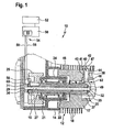
- FIG. 1 a first embodiment of a cleaning device according to the invention in the form of a scrubber 10 is shown with a cleaning tool according to the invention in the form of a roller brush 12.
- the roller brush 12 is rotatably mounted about a rotation axis 15 in a customary manner in a partially shown, underside open housing 14 and comprises a cylindrical base body 17, from which a plurality of cleaning bristles 18 protrude radially outward.
- the roller brush 12 can be rotated about the rotation axis 15 in rotation.
- a drive shaft 20 dips axially into the base body 17, designed as a hollow cylinder, which is rotatably mounted in a bearing sleeve 24 by means of a first ball bearing 21 and a second ball bearing 22 and is connected non-rotatably to the base body 17 in the usual way.
- the drive shaft 20 rotatably carries a pulley 25, in the usual manner via a drive belt, not shown in the drawing is coupled with a drive motor of the scrubber 10 also not shown in the drawing to achieve a better overview.
- the roller brush 12 can be rotated about the pulley 25 and the drive shaft 20 about the rotation axis 15 in rotation.
- the drive shaft 20 has a coaxial with the axis of rotation 15 extending through hole 27 and is made of an electrically conductive material, preferably made of a metal.
- the through hole 27 is penetrated by a metal rod 29 which is held by means of a first insulating sleeve 31 and a second insulating sleeve 32 at a distance from the drive shaft 20 and thus insulated from this.
- the metal rod 29 protrudes in the axial direction via the drive shaft 20 both with its first end facing away from the roller brush 12 and with its second end immersed in the base body 17 of the roller brush 12. At its first end, the metal rod 29 carries a first contact ring 34 and at its second end the metal rod 29 carries a second contact ring 35.
- the main body 17 defines a cavity 37.
- the base body 17 has a radially aligned passage 38, which is penetrated by a sensor element 40.
- the latter comprises a foil plate 41, on which a U-shaped conductor loop 42 is arranged.
- the conductor loop has a first leg 43 and a second leg 44, which are connected to one another in the region between the cleaning bristles 18 outside of the main body 17 via a web 47.
- a first sliding contact 48 is connected, which contacts the outside of the drive shaft 20 within the main body 17, and to the second leg 44, a second sliding contact 49 is connected, which contacts the front side of the second contact ring 35.
- a first sliding contact 48 is connected, which contacts the outside of the drive shaft 20 within the main body 17, and to the second leg 44, a second sliding contact 49 is connected, which contacts the front side of the second contact ring 35.
- about the sliding contacts 48 and 49 is thus the conductor loop 42 with the drive shaft 20 and the metal rod 29 in electrical connection.
- the scrubber 10 has a control device 50, to which a display device in the form of a display 52 is connected.
- a transmitter 55 of a detector device 54 is integrated, which is connected via a first connecting line 56 and a third sliding contact 58 with the pulley 25, which in turn is in electrical connection with the drive shaft 20.
- the transmitter 55 is connected via a second connecting line 59 and a fourth sliding contact 60 with the first contact ring 34 which is electrically connected to the metal rod 29 in connection.
- the evaluation electronics 55 is thus connected via the first connecting line 56, the third sliding contact 58, the pulley 25, the drive shaft 20 and the first sliding contact 48 with the first leg 43 of the conductor loop 42, and via the second connecting line 59, the fourth sliding contact 60, the first contact ring 34, the metal rod 29, the second contact ring 35 and the second sliding contact 49 is the evaluation electronics 55 with the second leg 44 of the conductor loop 42 in electrical connection.
- the cleaning bristles 18 of the roller brush 12 gradually wear, that is, they are increasingly shorter. This has the consequence that with prolonged operation of the roller brush 12, the cleaning bristles 18 with their free end practically the same distance to the outer side 46 of the body 17 as the outwardly projecting end of the film board 41. This causes the film board 41 in further operation the same way as the cleaning bristles 18 contacted the surface to be cleaned.
- the foil plate 41 is mechanically impaired and after a short time the conductor loop is interrupted in the region of the web 47. The interruption of the conductor loop 42 is detected by the transmitter 55 due to the now missing connection between the first connection line 56 and the second connection line 49 via the conductor loop 42.
- a signal is transmitted to the display 52, so that the user on the display 52 reaching the predetermined by the radial positioning of the film plate 41 in the passage 38 degree of wear of the roller brush 12 is displayed.
- the user does not need to check the roller brush 12 to see if the cleaning bristles 18 are worn so far that damage to the floor surface to be cleaned or at least an insufficient cleaning result, but rather the user Reaching the predetermined degree of wear on the display 52 is displayed. Should the scrubber 10 be mistakenly put into operation without the roller brush 12 is mounted in the housing 14, this would also be displayed to the user on the display 52, since in this case there is no electrical connection between the two connecting lines 56 and 59.
- FIG. 2 A second embodiment of a cleaning device according to the invention in the form of a scrubber-drier 65 with a cleaning tool according to the invention in the form of a roller brush 67 is shown in FIG FIG. 2 shown schematically.
- the roller brush 67 is rotatably mounted in a housing 69 which is open at the bottom about a rotation axis 70.
- the rotary drive of the roller brush 67 is carried out in the same manner as in the FIG. 1 illustrated roller brush 12 by means of a drive shaft.
- the drive shaft is not shown, but rather shows the FIG.
- This end face is rotatably mounted on a bearing sleeve 75 of the housing 69 by means of a ball bearing 72, which surrounds a bearing journal 73 of the main body 74 of the roller brush 67.
- a plurality of cleaning bristles 77 radially outward, and between the cleaning bristles 77 is a sensor element 40 is formed identical to the sensor element 80 arranged with a foil plate 81, the a conductor loop 82 carries.
- a sensor device 85 is arranged with the sensor element 80, but also a detector device 86 with an evaluation 87 and an energy source in the form of a battery 89.
- the roller brush 67 also has a display device in the form of a warning light 90, which at the free end of Trunnion 73 is arranged and can be observed by the user through a sight glass 91 therethrough.
- the indicator light 90 is connected on the one hand to the battery 89 and on the other hand to the transmitter 87.
- the transmitter is connected to the first leg 94 and the second leg 93 of the conductor loop 82 in electrical connection and is connected to the battery 89.
- the film board 81 st mechanically impaired until the conductor loop 82 is interrupted.
- the interruption of the conductor loop 82 is detected by the detector device 86, which then activates the control lamp designed, for example, in the form of an incandescent lamp or a light-emitting electrode, so that it emits an optical signal which can be recognized by the user.
- the user thus receives the signal that the predetermined by the radial position of the sensor element 80 degree of wear of the roller brush 67 is reached and this must be replaced.
- FIG. 3 a third embodiment of a cleaning device according to the invention in the form of a scrubber 100 is shown with a erfindunlicen cleaning tool in the form of a roller brush 102.
- the scrubber 100 and the roller brush 102 are substantially the same design as the above with reference to FIG. 1 shown scrubber 10 or roller brush 12. Identical components are therefore in FIG. 3 with the same reference numerals as in FIG. 1 and with respect to these components, reference is made to the foregoing explanations to avoid repetition.
- the detector device 54 is connected via inductive coupling elements to the sensor device 103 installed in the roller brush 102.
- the scrubber 100 has a first coil 105 which surrounds a ring-shaped coil carrier 107, projecting like a collar from a housing wall 106, in the direction of contact.
- the bobbin 107 is aligned coaxially with the bearing sleeve 24 and a cylindrical edge portion 109 of the base body 17 of the roller brush 102 dives into the annular bobbin 107.
- the edge portion 109 carries a second coil 110 whose ends are connected via connecting lines 111 and 112 to the conductor loop 42 of the sensor element 40 of the roller brush 102.
- the second coil 110 forms a component of the sensor device 103 installed in the roller brush 102, which sensor element comprises the sensor element 40 in addition to the second coil 110. Via the conductor loop 42 of the sensor element 40, the second coil 110 is short-circuited.
- the roller brush 102 rotates about its axis of rotation 15, and the second coil 110 performs a corresponding rotational movement within the first coil 105.
- the rotational movement of the second coil 110 has the consequence that in the first coil 105, an electrical voltage is induced, which can be detected by the detector device 55.
- the conductor loop 42 Upon reaching a predetermined degree of wear, as explained above, the conductor loop 42 is interrupted. This changes abruptly the ohmic resistance of the conductor loop 42 and thus a physical characteristic of the sensor element 40. This characteristic change is, as explained above, via the electrical contact elements in the form of the first coil 105 and the second coil 110 inductively detected by the detector device 54 and then displayed on the display 52 to the user.
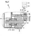
- FIG. 4 a fourth embodiment of a cleaning device according to the invention in the form of a scrubber 120 is shown with a cleaning tool according to the invention in the form of a roller brush 122.
- the scrubber 120 and the roller brush 122 are substantially identical to those described above with reference to FIG. 1 explained scrubber 10 or roller brush 12.
- FIG. 4 the same reference numerals as in FIG. 1 and with respect to these components, reference is made to the foregoing explanations to avoid repetition.
- the roller brush 122 has a sensor device 123 with a sensor element 40, which, as already explained in detail, has a conductor loop 42.
- the sensor device 123 comprises a transponder 125 FIG. 5 is clear, the transponder 125 includes an antenna coil 126, a read / write memory 127 and a control logic 128. Read / write memory 127 and control logic 128 are part of a microelectronic circuit 129, as well as the antenna coil 126 and the conductor loop 42 of the sensor element 40th is arranged on a common foil plate 131.
- the conductor loop 42 is connected in series with the antenna coil 126. If the conductor loop 42 is interrupted when a predetermined degree of wear of the roller brush 122 has been reached, as explained above, the transmission and reception properties of the antenna coil 126 change with it.
- the sensor device 123 integrated into the roller brush 122 is also assigned an external detector device 133.
- the reading device 135 is arranged on a ceiling wall 137 of the roller brush 122 accommodating the housing 14. With the help of the reading device 135, the read / write memory 127 of the transponder 125 can be read out without contact. In the read / write memory 127 tool-specific data can be stored to identify the roller brush 122nd
- the conductor loop 42 of the sensor element 40 is interrupted when a degree of wear of the roller brush 122 determined by the radial arrangement of the sensor element 40 in the base body 17 of the roller brush 122 is reached, then the transmission and reception properties of the antenna coil 126 abruptly change, so that radio signals are possibly worse Quality between the reader 135 and the transponder 125 can be transmitted.
- the reading device 135 can no longer recognize the transponder 125 at all, since it no longer receives a response signal from the transponder 125.
- the impaired or even completely interrupted signal transmission between the reading device 135 and the transponder 125 is detected by the evaluation electronics 134 of the detector device 133.
- the display 52 connected to the control device 50 of the scrubber 120 visually indicates to the user the achievement of the predetermined degree of wear.
- the absence of a roller brush 122 is also indicated in the event that the scrubber 120 has been erroneously put into operation without the roller brush 122 being previously mounted in the housing 14.
- FIG. 6 an alternative interconnection of the transponder 125 is shown schematically.
- the conductor loop 42 is not connected in series with the antenna coil 126 but connected to separate inputs 130, 138 of the control logic 128. If the conductor loop 42 is interrupted when a predetermined degree of wear is reached, this is detected by the control logic 128 and reported to the reading device 135 by means of the antenna coil 126. Even with interrupted conductor loop 42 can in the in FIG. 6 shown interconnection of the read / write memory 127 are read out by the reader 135, because the signal transmission between reader 135 and transponder 125 is not affected by the interruption of the conductor loop 42.
- FIG. 7 schematically a first arrangement and mounting option on a main body 140 is shown schematically.
- the main body 140 may be made of a plastic material, for example, on which cleaning bristles 18 and 77 are set to project radially outwards in a later production step, which is not shown in the drawing.
- the main body 140 has a recess 141 extending over a partial region of its circumference and also a partial region of its axial extension, which is covered by a cover 142.
- a foil plate 143 is fixed to the underside of the lid 142, which has a stamped, strip-shaped board region 144 which is folded radially outward.
- the stamped-out board area 144 protrudes with a free end portion 145 on the outside 146 of the lid 142 and the remaining portion of the board area 144 extends between the lid 142 and the edge of the recess 141.
- Die punched board area 144 then forms the above-described sensor element 40 or 80 and carries the conductor loop 42 and 82, whereas within the base body 140 on the remaining foil plate 143 further electrical components of a sensor device can be arranged, in particular the above with reference to FIG. 4 explained transponder 125.
- FIG. 8 A second advantageous possibility of arranging and mounting a radially outwardly projecting sensor element on a base body of a roller brush is in FIG. 8 shown.
- a base body 150 is used with a slot-shaped recess 151 extending over a partial region of its longitudinal extent, which extends from an axial end 152 of the base body 150 and extends over a partial region of the entire length of the base body 150.
- a stamped-out blank area 153 of a foil plate 154 is inserted.
- the punched-out board area 152 accommodates the above-explained conductor loop 42 or 82, and the remaining area of the foil board 154 accommodates further electrical components of the sensor device within the base body 150; in particular, it can carry a transponder 125.
- a two-part main body 160 is used with a first basic body part 161 and a second basic body part 162, which can be inserted into one another in the axial direction. Both basic body parts 161 and 162 are hollow.
- the first body part 161 similarly has the same design as described above with reference to FIG FIG. 6 already at the base body 150 has been explained, extending over a portion of its length extending slot-shaped recess 163 which extends from the second base body portion 162 facing the end 164 of the first body portion 161.
- punched out board area 165 may receive a conductor loop that will break when a predetermined degree of wear of the corresponding roller brush is reached, and the remaining area of foil board 166 may receive, for example, a transponder that may be contacted by an associated reader as long as the conductor loop is not interrupted is.
- the two main body parts 161 and 162 can be inserted into each other after inserting the foil plate 166 in the first base body part 161, and then in a further manufacturing step, a plurality of cleaning bristles on the outer sides of the two basic body parts 161 and 162 are set to form a roller brush for a scrubber.
- FIG. 10 Another arrangement and mounting possibility of a sensor element in the main body of a roller brush is in FIG. 10 illustrated by the example of a base body 170, which is designed in the form of a hollow cylinder.
- An annular carrier 171 can be inserted into the main body 170 on the front side, wherein the carrier 171 can be pressed with the main body 170.
- the carrier 171 comprises a ring member 172, to which an inner sleeve 173 is integrally formed, which is insertable into the base body 170.
- an outer sleeve 174 is pressed, after previously on the inner sleeve 173 a film board 175 was wound up.
- a stamped-out board portion 176 of the film board 175 is guided by a passage slot of the outer sleeve 174 not shown in the drawing in the manner of a flag to the outside and held by trunnions 177 on a plate-like web 178 which is integrally formed on the ring member 172.
- the web 178 can be inserted into a slot 179 of the base body 170, wherein then an end portion of the punched-out board area 176 projects radially outward from the base body 170.
- the web 178 supports the punched-out board area 176, which is clamped in a defined manner after insertion of the carrier into the base body 170 between one side of the slot 179 and the web 178, ie the position of the fixation of the board area 176 is uniquely predetermined by the web 178.
- the stamped-out board area 176 can carry a conductor loop in a corresponding manner, as already described, which is preferably electrically connected to a transponder arranged on the remaining area of the foil board 175, in particular with its antenna coil, as already explained above.
- the carrier 171 can be used in combination with the stamped-out board area 176 and the remaining area of the film board 175 for bodies of different thicknesses.
- FIGS. 11A to 11C schematically another arrangement and mounting possibility of a sensor element in the main body of a roller brush on the example of a base 180 is shown.
- This one is in the FIGS. 11A to 11C only partially illustrated. It is clear that it is in the form of a hollow cylinder and has a diametrically extending, stepped recess 181 with a first recess portion 182, which merges via a step 183 in a second recess portion 184, wherein the second recess portion 184 is considerably smaller than the first Recess portion 182.
- the first recess portion 182 extends through a cylinder wall 185 of the base body 180 and extends diametrically approximately to the center of the opposite cylinder wall 186. In the cylinder wall 186, the step 183 and the second recess portion 184 extend.
- a holder 188 can be inserted into the recess 181, which carries on its front side 189 a foil plate 190 with a foil strip 191 projecting forward from the front side 189.
- the holder 188 is made of an elastically deformable material, in particular of a plastic material and has on opposite outer sides in each case a latching wing 192 or 193.
- the holder 188 On the rear side 194 facing away from the front side 189, the holder 188 carries a lid 195.
- the foil strip 191 reaches through the second recess section 184 and protrudes with its free end over the outside of the main body 180 radially outward, and at the same time engage the elastic locking wings 192 and 193, the cylinder wall 185 and the lid 195 closes the first recess portion 182.
- the foil plate 190 is thus reliably fixed inside the hollow cylindrical body 180, wherein the outwardly projecting film strip 191, such as already described above, can carry a conductor loop, which is interrupted upon reaching a predetermined degree of wear of the corresponding roller brush.
- the remaining area of the foil plate 190 arranged within the basic body 180 can in turn carry a transponder, which is electrically connected to the conductor loop.
- FIG. 12 A corresponding embodiment of a cleaning device according to the invention in the form of a scrubber-drier 200 with a cleaning tool in the form of a roller brush 202 is shown in FIG. 12 shown schematically.
- the scrubber-drier 200 is designed substantially identical to the above with reference to the FIGS. 1 . 3 and 4 explained Scrubber 10, 100 and 120.
- FIG. 10 the same reference numerals as in the FIGS. 1 . 3 and 4 and with respect to these components, reference is made to the foregoing explanations to avoid repetition.
- the scrubber-drier 200 has an annular Fadenabweiser 203, which has a cylindrical edge portion 204 of a base 205 of the Roller brush 202 circumferentially surrounds.
- a reader 207 a detector device 208 is integrated, which in addition to the reader 207 has a transmitter 209, which is integrated into the control device 50 of the scrubber 200.
- the reader 207 is associated with a transponder 211, which is injected into a sleeve 212 of plastic surrounding the cylindrical edge portion 204 of the base body 205 and is in electrical connection with a sensor element 213 projecting axially from the sleeve 212.
- the sensor element 213 is designed as a foil board, which, as already explained several times, carries a conductor loop.
- the arrangement of the transponder 211 in the cylindrical edge portion 204 arranged sleeve 212, which is surrounded by the annular Fadenabweiser 203 which receives the associated reader 207, has the advantage that between the reader 207 and the transponder 211, a very small distance can be achieved , In particular, a distance of less than 10 mm. This ensures a particularly good signal transmission between the reader 207 and the transponder 212.
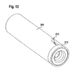
- FIG. 13 schematically, the main body 205 of the roller brush 202 is shown with pressed onto the cylindrical edge portion 204 sleeve 212 from which protrudes the foil plate with the sensor element 213 in the axial direction.
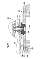
- FIG. 14 is a sixth embodiment of a cleaning device with a cleaning tool illustrated schematically in a partial view, wherein the cleaning tool is configured in the form of a disc brush 220.
- the disk brush 220 is rotatably mounted about a rotation axis 226 on a carrier plate 222 of a cleaning device 224 shown only in part. It comprises a base body in the form of an annular disc 228, which on the underside, that is, facing away from the carrier plate 222, carries a multiplicity of cleaning bristles 230.
- the annular disc 28 has a central passage opening 232, which is penetrated by a driver 234 which is rotationally fixed to a drive shaft 236 is held.
- the drive shaft can be rotated in the usual way by a known per se and therefore not shown in the drawing motor of the cleaning device 224 in rotation.
- the annular disc 228 carries a sensor device 238 with a transponder 239 and a sensor element 240, which is designed according to the above-described embodiments as a conductor loop and is arranged together with the transponder 239 on a flexible film board.
- the sensor element 240 passes through a passage 241 of the annular disc 228 and protrudes with its free end on the underside of the annular disc 228.
- the free end region of the sensor element 240 is arranged between the cleaning bristles 230.
- the transponder 239 is arranged on the cleaning bristles 230 facing away from the upper side of the annular disc 228.
- the carrier plate 222 carries on its underside, facing the transponder 239, an antenna 243 of an upper side arranged on the support plate 222 Reader 244.
- the reader 244 is connected to an evaluation of the cleaning device 224 according to the above-described embodiments. By means of the reader 244, a read / write memory of the transponder 239 can be read.
- the respective cleaning device has a cleaning tool with a sensor element which abruptly changes a physical characteristic, for example an electrical characteristic, in particular an ohmic resistance, for a given degree of wear of the cleaning tool, and this characteristic change can be detected by an associated detector device become.
- a physical characteristic for example an electrical characteristic, in particular an ohmic resistance
Description
Die Erfindung betrifft ein Reinigungswerkzeug für ein Reinigungsgerät mit den Merkmalen des Oberbegriffs von Patentanspruch 1.The invention relates to a cleaning tool for a cleaning device having the features of the preamble of claim 1.
Außerdem betrifft die Erfindung ein Reinigungsgerät zur Reinigung einer Fläche, insbesondere einer Bodenfläche, mit mindestens einem derartigen Reinigungswerkzeug.Moreover, the invention relates to a cleaning device for cleaning a surface, in particular a bottom surface, with at least one such cleaning tool.
Reinigungswerkzeuge von Flächenreinigungsgeräten, insbesondere von Bodenreinigungsgeräten, nutzen sich während ihres Betriebes ab. Bei Erreichen eines bestimmten Abnutzungsgrades müssen sie ausgetauscht werden, da ansonsten die Gefahr einer Beschädigung der zu reinigenden Fläche besteht und/oder das erzielbare Reinigungsergebnis unzureichend ist. Die Abnutzung des Reinigungswerkzeuges wird vom Benutzer üblicherweise kontrolliert, indem er das am Reinigungsgerät montierte Reinigungswerkzeug inspiziert. Dies ist allerdings in vielen Fällen mit Schwierigkeiten verbunden, da das Reinigungswerkzeug häufig in einem Gehäuse des Reinigungsgerätes montiert ist und deshalb vom Benutzer nicht ohne weiteres von außen eingesehen werden kann. So ist zum Beispiel bei Bodenreinigungsgeräten, insbesondere bei Scheuersaugmaschinen, das Reinigungswerkzeug, das in Form einer Scheiben- oder Walzenbürste ausgebildet ist, von Gehäuse- und Dichtungselementen umgeben.Cleaning tools of surface cleaning devices, in particular floor cleaning devices, wear during their operation. When reaching a certain degree of wear they must be replaced, otherwise there is a risk of damage to the surface to be cleaned and / or the achievable cleaning result is insufficient. The wear of the cleaning tool is usually controlled by the user by inspecting the cleaning tool mounted on the cleaning tool. However, this is in many cases associated with difficulties, since the cleaning tool is often mounted in a housing of the cleaning device and therefore can not be readily viewed by the user from the outside. Thus, for example, in floor cleaning appliances, especially in scrubber driers, the cleaning tool, which is in the form of a disc or roller brush, surrounded by housing and sealing elements.
Aus
Aufgabe der vorliegenden Erfindung ist es, ein Reinigungswerkzeug und ein entsprechendes Reinigungsgerät der eingangs genannten Art derart weiterzubilden, dass eine Abnutzung des Reinigungswerkzeuges einfacher erkannt werden kann.Object of the present invention is to develop a cleaning tool and a corresponding cleaning device of the type mentioned in such a way that wear of the cleaning tool can be easily detected.
Diese Aufgabe wird durch ein Reinigungswerkzeug mit den Merkmalen von Patentanspruch 1 gelöst.This object is achieved by a cleaning tool having the features of patent claim 1.
Das Reinigungswerkzeug wird mit einer Sensoreinrichtung ausgestattet, die ein Sensorelement aufweist, welches eine bestimmte physikalische Kenngröße hat. Diese Kenngröße ändert sich in Abhängigkeit vom Abnutzungsgrad des Reinigungswerkzeuges. Hierbei wird unter einer physikalischen Kenngröße des Sensorelementes eine bestimmte physikalische Eigenschaft verstanden, beispielsweise eine mechanische, optische, thermische, magnetische oder elektrische Eigenschaft des Sensorelementes, die sich mit der Abnutzung des Reinigungswerkzeuges ändert. Die Kenngrößenänderung kann mit Hilfe einer Detektoreinrichtung erfasst und an einer Anzeigeneinrichtung optisch und/oder akustisch angezeigt werden. Die Kopplung der Detektoreinrichtung mit der Sensoreinrichtung des Reinigungswerkzeuges kann drahtgebunden oder auch drahtlos erfolgen, das heißt die Kenngrößenänderung des Sensorelementes ist von der Detektoreinrichtung über einen drahtgebundenen oder drahtlosen Übertragungskanal erfassbar.The cleaning tool is equipped with a sensor device which has a sensor element which has a specific physical characteristic. This parameter changes depending on the degree of wear of the cleaning tool. In this case, a physical characteristic of the sensor element is understood to be a specific physical property, for example a mechanical, optical, thermal, magnetic or electrical characteristic of the sensor element, which changes with the wear of the cleaning tool. The characteristic change can be detected with the aid of a detector device and displayed visually and / or acoustically on a display device. The coupling of the detector device with the sensor device of the cleaning tool can be wired or even carried out wirelessly, that is, the characteristic change of the sensor element can be detected by the detector device via a wired or wireless transmission channel.
Erfindungsgemäß umfasst das Sensorelement eine elektrische Leiterschleife, die bei Erreichen eines vorgegebenen Abnutzungsgrades des Reinigungswerkzeuges unterbrechbar ist. Solange die Leiterschleife noch nicht unterbrochen ist, kann über die Leiterschleife ein Strom fließen. Dieser Stromfluss wird unterbrochen, sobald der vorgegebene Abnutzungsgrad des Reinigungswerkzeuges erreicht ist. Der Stromfluss kann kontaktlos oder kontaktbehaftet von einer zugehörigen Detektoreinrichtung erfasst werden. Die Unterbrechung des Stromflusses kann von der Detektoreinrichtung als Erreichen des vorgegebenen Abnutzungsgrades gewertet werden.According to the invention, the sensor element comprises an electrical conductor loop which can be interrupted upon reaching a predetermined degree of wear of the cleaning tool. As long as the conductor loop is not interrupted, a current can flow through the conductor loop. This current flow is interrupted as soon as the predetermined degree of wear of the cleaning tool is reached. The current flow can be detected contactless or contact-related by an associated detector device. The interruption of the current flow can be evaluated by the detector device as reaching the predetermined degree of wear.
Die Ausstattung des Reinigungswerkzeuges mit einem Sensorelement eröffnet somit eine einfache Möglichkeit, die Abnutzung des Reinigungswerkzeuges zu erkennen, ohne dass hierzu das Reinigungswerkzeug vom Benutzer inspiziert werden muss.The equipment of the cleaning tool with a sensor element thus provides a simple way to detect the wear of the cleaning tool, without requiring the cleaning tool must be inspected by the user.
Bei einer vorteilhaften Ausgestaltung der Erfindung weist die Sensoreinrichtung eine Spule auf, an die das Sensorelement angeschlossen ist. Die Spule kann beispielsweise über das Sensorelement kurzgeschlossen werden, das heißt das Sensorelement kann die beiden Spulenenden miteinander verbinden. Ändert sich aufgrund der Abnutzung des Reinigungswerkzeuges der Ohmsche Widersand, die Induktivität oder die Kapazität des Sensorelementes, so ändert sich damit auch die entsprechende Kenngröße des Gesamtsystems bestehend aus der Spule und dem Sensorelement. Die Spule ermöglicht eine induktive Kopplung des Sensorelementes mit einer zugeordneten Detektoreinrichtung des Reinigungsgerätes, wobei die Detektoreinrichtung ebenfalls eine Spule umfassen kann, die mit der Spule der Sensoreinrichtung induktiv zusammenwirkt.In an advantageous embodiment of the invention, the sensor device has a coil to which the sensor element is connected. The coil can be short-circuited, for example via the sensor element, that is, the sensor element can connect the two coil ends together. If, due to the wear of the cleaning tool, the ohmic resistance, the inductance or the capacitance of the sensor element changes, so does the corresponding parameter of the overall system consisting of the coil and the sensor element also change. The coil allows inductive coupling of the sensor element with an associated detector device the cleaning device, wherein the detector device may also include a coil which interacts inductively with the coil of the sensor device.
Von Vorteil ist es hierbei, wenn das Reinigungswerkzeug um eine Drehachse drehbar ist und die Spule der Sensoreinrichtung einen koaxial zur Drehachse ausgerichteten, vorzugsweise zylindrischen Abschnitt eines Grundkörpers des Reinigungswerkzeuges in Umfangsrichtung umgibt. Bei einer derartigen Ausgestaltung rotiert die in das Reinigungswerkzeug integrierte Spule während des Betriebes des Reinigungswerkzeuges. Die Detektoreinrichtung des Reinigungsgerätes kann eine entsprechende Spule umfassen, die gerätefest angeordnet ist. Die zusammen mit dem Grundkörper des Reinigungswerkzeuges rotierende Spule der Sensoreinrichtung kann dann in der Spule der Detektoreinrichtung eine elektrische Spannung induzieren, die von einer Auswerteelektronik der Detektoreinrichtung ausgewertet werden kann. Ändert sich die elektrische Kenngröße des an die Spule angeschlossenen Sensorelementes, so hat die Kenngrößenänderung Einfluss auf die in der Spule der Detektoreinrichtung induzierten Spannung, so dass die Kenngrößenänderung auf einfache Weise von der Auswerteelektronik der Detektoreinrichtung erfasst werden kann, ohne dass hierzu eine galvanische Kopplung zwischen der Sensoreinrichtung des Reinigungswerkzeuges und der Detektoreinrichtung des Reinigungsgerätes erforderlich ist.It is advantageous here if the cleaning tool is rotatable about an axis of rotation and the coil of the sensor device surrounds a preferably cylindrical section of a main body of the cleaning tool aligned coaxially with the axis of rotation in the circumferential direction. In such an embodiment, the integrated in the cleaning tool spool rotates during operation of the cleaning tool. The detector device of the cleaning device may comprise a corresponding coil, which is fixed to the device. The coil of the sensor device, which rotates together with the main body of the cleaning tool, can then induce an electrical voltage in the coil of the detector device, which voltage can be evaluated by evaluation electronics of the detector device. If the electrical parameter of the sensor element connected to the coil changes, the characteristic change has an influence on the voltage induced in the coil of the detector device so that the characteristic change can be detected in a simple manner by the evaluation electronics of the detector device, without a galvanic coupling between the sensor device of the cleaning tool and the detector device of the cleaning device is required.
Die Bereitstellung einer Detektoreinrichtung im Reinigungsgerät ist allerdings nicht zwingend erforderlich. Bei einer bevorzugten Ausgestaltung der Erfindung umfasst das Reinigungswerkzeug eine der Sensoreinrichtung zugeordnete Detektoreinrichtung, die mit einer Anzeigeeinrichtung verbindbar ist und die die Änderung der physikalischen Kenngröße des Sensorelementes detektiert. Bei einer derartigen Ausgestaltung weist das Reinigungswerkzeug also nicht nur die Sensoreinrichtung auf sondern zusätzlich auch die mit der Sensoreinrichtung gekoppelte Detektoreinrichtung. Beispielsweise kann die Detektoreinrichtung in Form einer Auswerteelektronik ausgestaltet sein, die in das Reinigungswerkzeug eingebaut ist.However, the provision of a detector device in the cleaning device is not absolutely necessary. In a preferred embodiment of the invention, the cleaning tool comprises a detector device associated with the detector device, which is connectable to a display device and which detects the change in the physical characteristic of the sensor element. In such a configuration, therefore, the cleaning tool not only has the sensor device but additionally also the detector device coupled to the sensor device. For example, the detector device can be designed in the form of an evaluation electronics, which is installed in the cleaning tool.
Von Vorteil ist es hierbei, wenn das Reinigungswerkzeug auch die Anzeigeeinrichtung und/oder eine Energiequelle umfasst. Die Anzeigeeinrichtung kann insbesondere in Form einer optischen und/oder akustischen Signaleinrichtung ausgebildet sein, beispielsweise in Form einer Kontrollleuchte, die mit der Detektoreinrichtung verbunden ist und vom Benutzer auf einfache Weise erkannt werden kann. Es kann insbesondere vorgesehen sein, dass die Kontrollleuchte koaxial zu einer Drehachse des Reinigungswerkzeuges ausgerichtet und hinter einer transparenten Abdeckung des Reinigungsgerätes angeordnet ist. Das Leuchten der Kontrollleuchte kann dem Benutzer den Hinweis geben, dass ein maximaler Abnutzungsgrad des Reinigungswerkzeuges erreicht ist und dieses folglich ausgetauscht werden muss.It is advantageous here if the cleaning tool also includes the display device and / or an energy source. The display device can be embodied in particular in the form of an optical and / or acoustic signal device, for example in the form of a warning light, which is connected to the detector device and can be easily recognized by the user. It can be provided, in particular, that the indicator light is aligned coaxially to a rotational axis of the cleaning tool and arranged behind a transparent cover of the cleaning device. The illumination of the indicator light can give the user the indication that a maximum degree of wear of the cleaning tool is reached and this must therefore be replaced.
Als in das Reinigungswerkzeug eingebaute Energiequelle kommt vorzugsweise eine elektrische Batterie zum Einsatz, insbesondere eine sogenannte Knopfzelle. Die Lebensdauer der Batterie kann beträchtlich größer gewählt werden als die Lebensdauer des Reinigungswerkzeuges, so dass sichergestellt ist, dass die Batterie ausreichend Energie bereitstellt, wenn ein maximaler Abnutzungsgrad des Reinigungswerkzeuges erreicht ist und dies dem Benutzer mittels der in das Reinigungswerkzeug eingebauten Anzeigeeinrichtung optisch und/oder akustisch angezeigt werden soll.As an energy source built into the cleaning tool, an electric battery is preferably used, in particular a so-called button cell. The life of the battery can be selected to be considerably greater than the life of the cleaning tool, so as to ensure that the battery provides sufficient energy when a maximum degree of wear of the cleaning tool is achieved and visually and / or visually inform the user by means of the display device incorporated into the cleaning tool should be displayed acoustically.
Es kann auch vorgesehen sein, dass die Sensoreinrichtung elektrische Kontaktelemente aufweist zum Verbinden der Sensoreinrichtung mit einer externen Detektoreinrichtung, die die Änderung der physikalischen Kenngröße des Sensorelementes detektiert. Als elektrische Kontaktelemente kommen bevorzugt Schleifkontakte zum Einsatz, über die während des Betriebes des Reinigungswerkzeuges eine elektrische Verbindung zwischen der Sensoreinrichtung des Reinigungswerkzeuges und der zugeordneten externen Detektoreinrichtung sichergestellt ist. So kann beispielsweise vorgesehen sein, dass das Reinigungswerkzeug um eine Drehachse drehbar ist, wobei der Drehantrieb über einen drehfest mit dem Reinigungswerkzeug verbindbaren Antriebszapfen erfolgt, welcher über Getriebeelemente, beispielsweise über einen Riementrieb, mit einem Motor des Reinigungsgerätes verbunden ist. Der Antriebszapfen kann zumindest teilweise aus einem elektrisch leitenden Material gefertigt sein und somit einen ersten elektrischen Leiter ausbilden. Außerdem kann der Antriebszapfen von einem zweiten elektrischen Leiter durchgriffen werden, der gegenüber dem Antriebszapfen isoliert ist. Über die beiden elektrischen Leiter kann eine elektrische Verbindung zwischen der in das Reinigungswerkzeug eingebauten Sensoreinrichtung und der externen Detektoreinrichtung hergestellt werden.It can also be provided that the sensor device has electrical contact elements for connecting the sensor device to an external detector device, which detects the change in the physical parameter of the sensor element. As electrical contact elements are preferably sliding contacts are used, through which an electrical connection between the sensor device of the cleaning tool and the associated external detector device is ensured during operation of the cleaning tool. Thus, for example, be provided that the cleaning tool is rotatable about an axis of rotation, wherein the rotary drive via a rotatably connected to the cleaning tool drive pin takes place, which is connected via transmission elements, for example via a belt drive, with a motor of the cleaning device. The drive pin may be made at least partially of an electrically conductive material and thus form a first electrical conductor. In addition, the drive pin can be penetrated by a second electrical conductor which is insulated from the drive pin. An electrical connection between the sensor device installed in the cleaning tool and the external detector device can be established via the two electrical conductors.
Bevorzugt weist die Sensoreinrichtung elektrische Kopplungselemente auf zur drahtlosen Kopplung der Sensoreinrichtung mit einer externen Detektoreinrichtung, die die physikalischen Kenngröße des Sensorelementes detektiert. Hierzu können beispielsweise optische, induktive oder kapazitive Kopplungselemente zum Einsatz kommen oder auch Kopplungselemente, die sensitiv sind gegenüber einem elektromagnetischen Wechselfeld, beispielsweise Antennen. Über die elektrischen Kopplungselemente kann ein drahtloser Übertragungskanal zwischen der Sensoreinrichtung des Reinigungswerkzeuges und der externen Detektoreinrichtung errichtet werden. Insbesondere gibt dies die Möglichkeit, eine Funkverbindung zwischen den beiden Einrichtungen aufzubauen.The sensor device preferably has electrical coupling elements for wireless coupling of the sensor device to an external detector device, which detects the physical parameter of the sensor element. For this example, optical, inductive or capacitive coupling elements may be used or coupling elements that are sensitive to an alternating electromagnetic field, such as antennas. Via the electrical coupling elements, a wireless transmission channel between the sensor device of the cleaning tool and the external detector device can be established. In particular, this gives the possibility of establishing a radio link between the two devices.
Bei einer besonders bevorzugten Ausgestaltung des erfindungsgemäßen Reinigungswerkzeuges weist dessen Sensoreinrichtung zumindest ein elektrisches Speicherelement auf, beispielsweise einen beschreibbaren und auslesbaren Schreib-/Lesespeicher. Dies gibt die Möglichkeit, werkzeugspezifische Daten oder auch ein Rechenprogramm in der Sensoreinrichtung abzuspeichern. Beispielsweise kann eine Identifikationsnummer des Reinigungswerkzeuges in der Sensoreinrichtung hinterlegt werden, wobei die Identifikationsnummer das Reinigungswerkzeug eindeutig charakterisiert. Diese Identifikationsnummer kann von der Detektoreinrichtung, die der Sensoreinrichtung zugeordnet ist, ausgelesen und ausgewertet werden.In a particularly preferred embodiment of the cleaning tool according to the invention, the sensor device has at least one electrical storage element, for example a writable and readable write / read memory. This makes it possible to store tool-specific data or even a computer program in the sensor device. For example, an identification number of the cleaning tool can be stored in the sensor device, wherein the identification number uniquely characterizes the cleaning tool. This identification number can be read out and evaluated by the detector device which is assigned to the sensor device.
Günstig ist es, wenn die Sensoreinrichtung programmierbar ist.It is favorable if the sensor device is programmable.
Die Sensoreinrichtung kann beispielsweise einen mikroelektronischen Schaltkreis umfassen, der elektrisch mit dem Sensorelement verbunden ist.The sensor device may comprise, for example, a microelectronic circuit which is electrically connected to the sensor element.
Bei einer besonders bevorzugten Ausgestaltung der Erfindung weist die Sensoreinrichtung einen Transponder auf, das heißt ein Funk-Kommunikationsglied, welches eingehende Signale aufnimmt und beantwortet. Mittels des Transponders kann ein drahtloser Übertragungskanal zwischen der Sensoreinrichtung des Reinigungswerkzeuges und einer externen Detektoreinrichtung erzielt werden. Der Transponder weist einen Datenspeicher auf in Form eines Schreib-/Lesespeichers und kann zusätzlich auch eine Steuerlogik umfassen. Er kann mit einer Sende- und Empfangsantenne in elektrischer Verbindung stehen. Vorzugsweise weist der Transponder eine Antennenspule auf. Durch induktive Kopplung mit einem zugeordneten Lesegerät kann der Transponder mit Energie versorgt und sein Datenspeicher kann ausgelesen werden. Es kann allerdings auch vorgesehen sein, dass der Transponder mit einer eigenen Stromquelle ausgestattet ist. Solche Kombinationen aus einem Transponder und einem Lesegerät sind allgemein unter dem Begriff RFID-Technologie (Radio Frequency Identification) bekannt.In a particularly preferred embodiment of the invention, the sensor device has a transponder, that is to say a radio communication element which receives and answers incoming signals. By means of the transponder, a wireless transmission channel between the sensor device of the cleaning tool and an external detector device be achieved. The transponder has a data memory in the form of a read / write memory and may additionally include a control logic. It can be in electrical connection with a transmitting and receiving antenna. Preferably, the transponder has an antenna coil. By inductive coupling with an associated reading device, the transponder can be supplied with energy and its data memory can be read out. However, it can also be provided that the transponder is equipped with its own power source. Such combinations of a transponder and a reader are generally known by the term RFID (Radio Frequency Identification) technology.
Von besonderem Vorteil ist es, wenn das Sensorelement eine elektrische Leiterschleife aufweist, die in die Antenne des Transponders geschaltet ist und die bei Erreichen eines vorgegebenen Abnutzungsgrades des Reinigungswerkzeuges unterbrechbar ist. Hat das Reinigungswerkzeug den vorgegebenen Abnutzungsgrad erreicht, so wird die elektrische Leiterschleife unterbrochen. Dies hat zur Folge, dass die Datenübertragung zwischen dem Transponder und einem zugeordneten Lesegerät zumindest beeinträchtigt oder gar vollständig unterbrochen wird. Die Beeinträchtigung oder Unterbrechung der Datenübertragung kann von der zugeordneten Detektoreinrichtung, die das mit dem Transponder zusammenwirkende Lesegerät aufweist, erkannt werden. Es kann dann an einer mit der Detektoreinrichtung verbundenen Anzeigeeinrichtung angezeigt werden, dass das Reinigungswerkzeug seinen vorgegebenen Abnutzungsgrad erreicht hat. Da eine fehlende Datenübertragung zwischen dem Lesegerät und dem Transponder auch vorliegt, wenn überhaupt kein Reinigungswerkzeug in das Reinigungsgerät eingebaut wurde, kann aufgrund der fehlenden Datenübertragung dem Benutzer auch angezeigt werden, dass versehentlich kein Reinigungswerkzeug in das Reinigungsgerät eingebaut wurde und ein Betrieb desselben somit nicht möglich ist.It is particularly advantageous if the sensor element has an electrical conductor loop, which is connected in the antenna of the transponder and which can be interrupted upon reaching a predetermined degree of wear of the cleaning tool. If the cleaning tool has reached the predetermined degree of wear, the electrical conductor loop is interrupted. This has the consequence that the data transmission between the transponder and an associated reading device is at least impaired or even completely interrupted. The impairment or interruption of the data transmission can be detected by the associated detector device, which has the reader interacting with the transponder. It can then be displayed on a display device connected to the detector device that the cleaning tool has reached its predetermined degree of wear. Since a lack of data transmission between the reader and the transponder is present even if no cleaning tool was installed in the cleaning device, the user can also be displayed due to the lack of data transmission that accidentally no cleaning tool has been installed in the cleaning device and its operation is therefore not possible.
Alternativ kann vorgesehen sein, dass der Transponder einen elektrischen Schaltkreis aufweist, an den das Sensorelement und die Antenne angeschlossen sind, wobei mittels des elektrischen Schaltkreises die Änderung der physikalischen Kenngröße des Sensorelementes erfassbar und ein entsprechendes Signal an die Antenne ausgebbar ist. Das Sensorelement kann beispielsweise als Leiterschleife ausgestaltet sein, die bei Vorliegen eines vorgegebenen Abnutzungsgrades des Reinigungswerkzeuges unterbrochen wird. Das Unterbrechen der Leiterschleife wird vom elektrischen Schaltkreis des Transponders erkannt und über die Antenne an das zugeordnete Lesegerät gemeldet. Bei einer derartigen Ausgestaltung wird die Antenne nicht durch das Sensorelement beeinträchtigt, unabhängig vom Abnutzungsgrad des Reinigungswerkzeuges ist mittels der Antenne eine Funkverbindung zwischen dem Lesegerät und dem Transponder sichergestellt. Der Transponder kann somit jederzeit vom Lesegerät abgefragt werden, Daten können ausgetauscht werden, beispielsweise Identifikationsnummern, und davon unabhängig kann auch die Änderung der physikalischen Kenngröße des Sensorelementes dem Lesegerät gemeldet werden.Alternatively it can be provided that the transponder has an electrical circuit to which the sensor element and the antenna are connected, wherein by means of the electrical circuit, the change in the physical characteristic of the sensor element can be detected and a corresponding signal can be output to the antenna. The sensor element may for example be designed as a conductor loop, which is interrupted in the presence of a predetermined degree of wear of the cleaning tool. The interruption of the conductor loop is detected by the electrical circuit of the transponder and reported via the antenna to the associated reader. In such an embodiment, the antenna is not affected by the sensor element, regardless of the degree of wear of the cleaning tool, a radio connection between the reader and the transponder is ensured by means of the antenna. The transponder can thus be queried at any time by the reader, data can be exchanged, such as identification numbers, and independently of this, the change in the physical characteristic of the sensor element can be reported to the reader.
Die Anordnung des Transponders an oder im Reinigungswerkzeug kann auf verschiedene Weise erfolgen. Günstig ist es, wenn nach dem Einbau des Reinigungswerkzeuges in das Reinigungsgerät ein möglichst geringer Abstand zwischen der Antenne des Transponders und der Antenne des zugeordneten Lesegeräts der Detektoreinrichtung vorliegt. So kann beispielsweise vorgesehen sein, dass das Reinigungswerkzeug um eine Drehachse drehbar ist und einen Grundkörper aufweist mit einem ringförmigen, koaxial zur Drehachse ausgerichteten Bereich und die Antenne des Transponders in diesem Bereich angeordnet ist. Der ringförmige Bereich des Grundkörpers kann im montierten Zustand des Reinigungswerkzeuges in einen zugeordneten Aufnahmering des Reinigungsgerätes eintauchen, und in den Aufnahmering kann die Antenne des mit dem Transponder zusammenwirkenden Lesegeräts der Detektoreinrichtung integriert sein. Dadurch kann ein sehr geringer Abstand zwischen den Antennen und folglich eine gute Signalübertragung erreicht werden, ohne dass die Reinigungswirkung des Reinigungswerkzeuges beeinträchtigt wird. Es kann auch vorgesehen sein, dass der ringförmige Bereich einer Tragplatte des Reinigungsgerätes gegenüberliegt im montierten Zustand des Reinigungswerkzeuges. An der Tragplatte kann die Antenne des Lesegeräts angeordnet sein, so dass eine gute Signalübertragung zwischen Transponder und Lesegerät erzielt werden kann.The arrangement of the transponder on or in the cleaning tool can be done in various ways. It is favorable if, after installation of the cleaning tool in the cleaning device, the smallest possible distance between the antenna of the transponder and the antenna of the associated reading device of the detector device is present. For example, it may be provided that the cleaning tool is rotatable about an axis of rotation and a Basic body has arranged with an annular, coaxial with the axis of rotation aligned area and the antenna of the transponder in this area. In the assembled state of the cleaning tool, the annular region of the basic body can dip into an associated receiving ring of the cleaning device, and the antenna of the reading device of the detector device cooperating with the transponder can be integrated in the receiving ring. This allows a very small distance between the antennas and consequently a good signal transmission can be achieved without the cleaning effect of the cleaning tool is impaired. It can also be provided that the annular region of a support plate of the cleaning device is opposite in the assembled state of the cleaning tool. On the support plate, the antenna of the reader can be arranged so that a good signal transmission between the transponder and the reader can be achieved.
Zur Lage des Sensorelementes am oder im Reinigungswerkzeug wurden bisher keine näheren Angaben gemacht. Bei einer vorteilhaften Ausführungsform ist vorgesehen, dass das Reinigungswerkzeug um eine Drehachse drehbar ist und einen koaxial zur Drehachse ausgerichteten Grundkörper aufweist, von dem das Sensorelement bezogen auf die Drehachse radial oder axial absteht.For the location of the sensor element on or in the cleaning tool so far no details have been made. In an advantageous embodiment it is provided that the cleaning tool is rotatable about an axis of rotation and has a coaxially aligned with the axis of rotation base body from which the sensor element projects radially or axially relative to the axis of rotation.
Günstig ist es für die Montage des Sensorelementes, wenn dieses mit dem Grundkörper verrastbar oder verklemmbar ist. Das Sensorelement kann beispielsweise an einer Halterung montierbar sein, die in eine korrespondierende Aufnahme des Grundkörpers einsetzbar und mit diesem verrastbar ist.It is favorable for the mounting of the sensor element, if this can be latched or clamped to the base body. The sensor element can be mounted, for example, on a holder, which can be inserted into a corresponding receptacle of the base body and latched thereto.
Das Sensorelement ist bevorzugt flexibel ausgestaltet, das heißt es ist verformbar, insbesondere kann es biegbar ausgebildet sein.The sensor element is preferably made flexible, that is, it is deformable, in particular, it may be formed bendable.
Um das Sensorelement während des Betriebes des Reinigungswerkzeuges vor starken mechanischen Beeinträchtigungen zu schützen, ist es günstig, wenn in Drehrichtung des Reinigungswerkzeuges vor und hinter dem Sensorelement Reinigungselemente des Reinigungswerkzeuges angeordnet sind. Das Reinigungswerkzeug kann beispielsweise in Form einer Scheiben- oder Walzenbürste ausgestaltet sein mit einem Grundkörper, von dem einen Vielzahl von Reinigungsborsten abstehen. Die Reinigungsborsten bilden Reinigungselemente aus, zwischen denen das Sensorelement angeordnet ist und an denen sich das Sensorelement bei Drehung der Scheiben- oder Walzenbürste abstützen kann.In order to protect the sensor element during operation of the cleaning tool from severe mechanical damage, it is advantageous if in the direction of rotation of the cleaning tool in front of and behind the sensor element cleaning elements of the cleaning tool are arranged. The cleaning tool can be configured, for example, in the form of a disk or roller brush with a base body, from which protrude a plurality of cleaning bristles. The cleaning bristles form cleaning elements, between which the sensor element is arranged and on which the sensor element can be supported upon rotation of the disc or roller brush.
Zur Verbesserung der Stütz- und Schützfunktion kann in Drehrichtung des Reinigungswerkzeuges vor und hinter dem Sensorelement eine dichtere Beborstung vorgesehen sein, d.h. eine höhere Dichte der Reinigungsborsten.To improve the support and contactor function in the direction of rotation of the cleaning tool in front of and behind the sensor element a denser bristles be provided, i. a higher density of cleaning bristles.
Bei einer vorteilhaften Ausführungsform ist das Sensorelement auf einer Folienplatine angeordnet. Unter einer Folienplatine wird hierbei eine flexible elektrische Leiterplatte verstanden, das heißt eine dünne, flexible Folie, die gebogen werden kann.In an advantageous embodiment, the sensor element is arranged on a foil board. In this case, a film board is understood to be a flexible electrical circuit board, that is to say a thin, flexible film which can be bent.
Auf der Folienplatine ist bei einer vorteilhaften Ausführungsform ein elektrisch mit dem Sensorelement verbundener Transponder angeordnet, das heißt die Folienplatine trägt sowohl das Sensorelement als auch den Transponder.In an advantageous embodiment, a transponder electrically connected to the sensor element is arranged on the foil board, that is to say the foil board carries both the sensor element and the transponder.
Vorzugsweise ist die Folienplatine an einem Träger gehalten, der axial in einen Grundkörper des Reinigungswerkzeuges einsetzbar ist. Der Träger kann eine Hülse ausbilden, auf der die Folienplatine fixiert, insbesondere aufgewickelt werden kann. Der Träger kann beispielsweise ringförmig ausgestaltet und bezogen auf die Drehachse des Grundkörpers in axialer Richtung mit diesem verbindbar sein. Bevorzugt weist der Träger ein Stützelement auf, an dem das Sensorelement anliegt.Preferably, the foil plate is held on a carrier which is axially insertable into a base body of the cleaning tool. The carrier can form a sleeve on which the foil plate can be fixed, in particular wound up. The carrier may be configured, for example, annular and with respect to the axis of rotation of the body in the axial direction with this connectable. Preferably, the carrier has a support element against which the sensor element rests.
Wie bereits erläutert, kann das Reinigungswerkzeug als drehbar gelagerte Walzenbürste ausgestaltet sein mit einem zylindrischen Grundkörper, von dem eine Vielzahl von Reinigungsborsten nach außen abstehen, wobei das Sensorelement zwischen den Reinigungsborsten angeordnet ist.As already explained, the cleaning tool can be configured as a rotatably mounted roller brush with a cylindrical base body, from which a plurality of cleaning bristles project outwards, wherein the sensor element is arranged between the cleaning bristles.
Alternativ kann das Reinigungswerkzeug als drehbar gelagerte Scheibenbürste ausgestaltet sein mit einem plattenartigen Grundkörper, von dessen Unterseite eine Vielzahl von Reinigungsborsten abstehen, wobei das Sensorelement zwischen den Reinigungsborsten angeordnet ist.Alternatively, the cleaning tool can be designed as a rotatably mounted disc brush with a plate-like base body, projecting from the underside of a plurality of cleaning bristles, wherein the sensor element is arranged between the cleaning bristles.
Wie eingangs erwähnt, betrifft die Erfindung auch ein Reinigungsgerät zur Reinigung einer Fläche, insbesondere einer Bodenfläche, mit einem Reinigungswerkzeug, das während seines Betriebes einer Abnutzung unterliegt. Das Reinigungsgerät weist mindestens ein Reinigungswerkzeug der voranstehend erläuterten Art auf sowie eine Detektoreinrichtung, die zum Erfassen der Änderung der physikalischen Kenngröße des Sensorelementes mit der Sensoreinrichtung gekoppelt ist, und das Reinigungsgerät weist auch eine Anzeigeeinrichtung auf, die mit der Detektoreinrichtung verbunden ist und an der eine Abnutzung des Reinigungswerkzeuges optisch und/oder akustisch angezeigt werden kann.As mentioned above, the invention also relates to a cleaning device for cleaning a surface, in particular a floor surface, with a cleaning tool that is subject to wear during its operation. The cleaning device has at least one cleaning tool of the type described above and a detector device which is coupled to detect the change in the physical characteristic of the sensor element with the sensor device, and the cleaning device also has a display device which is connected to the detector device and to the one Wear of the cleaning tool can be visually and / or acoustically displayed.
Das Reinigungsgerät ermöglicht es einem Benutzer auf einfache Weise, eine Abnutzung des Reinigungswerkzeuges zu erkennen. Hierzu ist das Reinigungswerkzeug, wie voranstehend beschrieben, mit einem Sensorelement ausgestattet, welches eine sich in Abhängigkeit von der Abnutzung des Reinigungswerkzeuges ändernde physikalische Kenngröße hat. Die Kenngrößenänderung kann von der Detektoreinrichtung des Reinigungsgerätes erkannt werden, die hierzu kontaktlos oder auch kontaktbehaftet mit der Sensoreinrichtung des Reinigungswerkzeuges gekoppelt ist. An einer Anzeigeeinrichtung kann dem Benutzer bei Vorliegen einer Kenngrößenänderung das Erreichen eines bestimmten Abnutzungsgrades des Reinigungswerkzeuges angezeigt werden.The cleaning device allows a user to easily detect a wear of the cleaning tool. For this purpose, the cleaning tool, as described above, equipped with a sensor element which has a depending on the wear of the cleaning tool changing physical characteristic. The characteristic change can be detected by the detector device of the cleaning device, which is for this purpose contactless or contact-coupled with the sensor device of the cleaning tool. At a display device, the user can be displayed in the presence of a characteristic change, the achievement of a certain degree of wear of the cleaning tool.
Die Detektoreinrichtung weist bevorzugt eine in eine Steuereinrichtung des Reinigungsgerätes integrierte Auswerteelektronik auf und ist über kontaktlose oder kontaktbehaftete Kontaktelemente mit der in das Reinigungswerkzeug integrierten Sensoreinrichtung verbunden. Insbesondere kann vorgesehen sein, dass die Detektoreinrichtung über elektrische Leitungen mit der Sensoreinrichtung verbunden ist.The detector device preferably has evaluation electronics integrated into a control device of the cleaning device and is connected via contactless or contact-type contact elements to the sensor device integrated in the cleaning tool. In particular, it can be provided that the detector device is connected to the sensor device via electrical lines.
Bevorzugt umfasst die Detektoreinrichtung elektrische Kopplungselemente zur drahtlosen Kopplung der Detektoreinrichtung mit der Sensoreinrichtung des Reinigungswerkzeuges. Hierzu können zum Beispiel optische, induktive oder kapazitive Kopplungselemente zum Einsatz kommen oder auch Kopplungselemente, die gegenüber einem elektromagnetischen Wechselfeld sensitiv sind, insbesondere Sender und/oder Empfänger von Funksignalen, beispielsweise eine Antenne.The detector device preferably comprises electrical coupling elements for the wireless coupling of the detector device to the sensor device of the cleaning tool. For this purpose, it is possible, for example, to use optical, inductive or capacitive coupling elements or also coupling elements that are sensitive to an electromagnetic alternating field, in particular transmitter and / or receiver of radio signals, for example an antenna.
Bei einer vorteilhaften Ausgestaltung des erfindungsgemäßen Reinigungsgerätes umfasst die Detektoreinrichtung eine Spule, die einen ringförmigen Abschnitt eines Grundkörpers des Reinigungswerkzeuges in Umfangsrichtung umgibt. Die Spule ermöglicht eine induktive Kopplung der Detektoreinrichtung mit der Sensoreinrichtung des Reinigungswerkzeuges.In an advantageous embodiment of the cleaning device according to the invention, the detector device comprises a coil which surrounds an annular portion of a base body of the cleaning tool in the circumferential direction. The coil allows inductive coupling of the detector device with the sensor device of the cleaning tool.
Es kann auch vorgesehen sein, dass die Detektoreinrichtung ein Lesegerät zum Auslesen eines Transponders des Reinigungswerkzeuges aufweist. Das Lesegerät umfasst hierzu eine Antenne, vorzugsweise eine Antennenspule, mit deren Hilfe ein bidirektionaler kontaktloser Übertragungskanal zwischen dem Lesegerät und dem Transponder errichtet werden kann. Insbesondere kann mittels des Lesegerätes ein Datenspeicher des Transponders ausgelesen oder beschrieben werden.It can also be provided that the detector device has a reading device for reading out a transponder of the cleaning tool. For this purpose, the reading device comprises an antenna, preferably an antenna coil, by means of which a bidirectional contactless transmission channel can be established between the reading device and the transponder. In particular, a data memory of the transponder can be read or written by means of the reading device.
Die Antenne des Lesegeräts ist bevorzugt in einem möglichst kurzen Abstand zur Antenne des Transponders des Reinigungswerkzeuges angeordnet. So kann beispielsweise vorgesehen sein, dass die Lesegerät-Antenne an oder in einem das Reinigungswerkzeug aufnehmenden Gehäuse des Reinigungsgerätes angeordnet ist, insbesondere an oder in einer das Reinigungswerkzeug überdeckenden Deckenwand des Gehäuses.The antenna of the reading device is preferably arranged in the shortest possible distance from the antenna of the transponder of the cleaning tool. For example, it may be provided that the reading device antenna is arranged on or in a housing of the cleaning device accommodating the cleaning tool, in particular on or in a cover wall of the housing covering the cleaning tool.
Besonders günstig ist es, wenn die Antenne des Lesegeräts an oder in einem Ring angeordnet ist, der einen zylindrischen Randabschnitt eines Grundkörpers des Reinigungswerkzeuges in Umfangsrichtung umgibt. Der Randabschnitt des Grundkörpers ist vorzugsweise kolinear zum Ring des Reinigungsgerätes angeordnet, insbesondere kann vorgesehen sein, dass der Randabschnitt des Grundkörpers in den Ring eintaucht. Am oder im Randabschnitt kann die Antenne des Transponders des Reinigungsgerätes positioniert sein und an oder in dem den Randabschnitt umgebenden Ring kann die zugeordnete Antenne des Lesegeräts angeordnet sein.It is particularly favorable when the antenna of the reading device is arranged on or in a ring which surrounds a cylindrical edge section of a main body of the cleaning tool in the circumferential direction. The edge section of the Base body is preferably arranged co-linear with the ring of the cleaning device, in particular it can be provided that the edge portion of the base body dips into the ring. The antenna of the transponder of the cleaning device can be positioned on or in the edge section, and the associated antenna of the reading device can be arranged on or in the ring surrounding the edge section.
Bei einer vorteilhaften Ausgestaltung ist das Reinigungswerkzeug an einem Lager des Reinigungsgerätes drehbar gelagert und die Antenne des Lesegeräts ist an oder in einem das Lager in Umfangsrichtung umgebenden Ring positioniert. Dies ermöglicht einen besonders kurzen Abstand zwischen der Antenne des Lesegeräts und der Antenne des Transponders und damit eine besonders störungsunempfindliche Signalübertragung.In an advantageous embodiment, the cleaning tool is rotatably mounted on a bearing of the cleaning device and the antenna of the reader is positioned on or in a ring surrounding the bearing in the circumferential direction. This allows a particularly short distance between the antenna of the reader and the antenna of the transponder and thus a particularly interference-insensitive signal transmission.
Von besonderem Vorteil ist es, wenn der das Lager des Reinigungsgerätes umgebende Ring als Fadenabweiser ausgestaltet. Derartige Fadenabweiser verhindern, dass sich um eine Antriebswelle oder eine Lagerachse des Reinigungswerkzeuges Fäden, Schnüre oder sonstige längliche Gegenstände wickeln und dadurch die Drehung des Reinigungswerkzeuges beeinträchtigen. Fadenabweiser kommen beispielsweise bei Scheuersaugmaschinen und Kehrmaschinen zum Einsatz, deren Reinigungswerkzeuge als Walzenbürsten ausgebildet sind. Die Walzenbürsten weisen einen zylindrischen Grundkörper auf, dessen stirnseitige Endabschnitte im montierten Zustand jeweils von einem ringförmigen Fadenabweiser umgeben sind. Der Abstand zwischen Fadenabweiser und Grundkörper ist sehr gering, er kann beispielsweise maximal 10 mm, insbesondere etwa 5 bis ca. 10 mm betragen. Einer der Randabschnitte des Grundkörpers kann einen Transponder der Sensoreinrichtung aufnehmen und der diesen Randabschnitt umgebende Fadenabweiser kann das zugeordnete Lesegerät aufnehmen, so dass per Funk auf einfache Weise Signale zwischen dem Lesegerät und dem Transponder ausgetauscht werden können. Aufgrund des geringen Abstandes zwischen dem Transponder und dem Lesegerät können kleine Antennen verwendet werden und dennoch kann eine gute Signalübertragung erzielt werden. An den Transponder kann das Sensorelement, vorzugsweise in Form einer Leiterschleife, angeschlossen sein. Wird bei Erreichen eines vorgegebenen Abnutzungsgrades die Leiterschleife unterbrochen, so kann dies beispielsweise eine Beeinträchtigung oder gar vollständige Unterbrechung der Signalübertragung zwischen Lesegerät und Transponder zur Folge und von der Detektoreinrichtung erkannt werden, und daraufhin kann an der Anzeigeeinrichtung ein optischer oder akustisches Signal generiert werden, das den Benutzer das Erreichen des vorgegebenen Abnutzungsgrades des Reinigungswerkzeuges anzeigt. Alternativ kann bei aufrecht erhaltener Signalübertragung die Unterbrechung der Leiterschleife vom Transponder über das Lesegerät der Detektoreinrichtung gemeldet werden, die daraufhin an der Anzeigeeinrichtung ein entsprechendes Signal generiert.It is particularly advantageous if the ring surrounding the bearing of the cleaning device is configured as a thread deflector. Such Fadenabweiser prevent winding around a drive shaft or a bearing axis of the cleaning tool threads, cords or other elongated objects, thereby affecting the rotation of the cleaning tool. Thread deflectors are used, for example, in scrubber driers and sweepers whose cleaning tools are designed as roller brushes. The roller brushes have a cylindrical base body, whose end-side end portions are each surrounded by an annular Fadenabweiser in the mounted state. The distance between the thread deflector and the base body is very small, for example, it can be a maximum of 10 mm, in particular about 5 to about 10 mm. One of the edge sections of the basic body can receive a transponder of the sensor device and the Fadenabweiser surrounding this edge portion can record the associated reader, so that signals can be exchanged between the reader and the transponder in a simple way by radio. Due to the small distance between the transponder and the reader small antennas can be used and still a good signal transmission can be achieved. The sensor element, preferably in the form of a conductor loop, can be connected to the transponder. If the conductor loop is interrupted when a predetermined degree of wear is reached, this can result, for example, in an impairment or even complete interruption of the signal transmission between the reading device and the transponder and can be detected by the detector device, and then an optical or acoustic signal can be generated on the display device the user indicates the achievement of the predetermined degree of wear of the cleaning tool. Alternatively, when the signal transmission is maintained, the interruption of the conductor loop from the transponder can be reported to the detector device via the reading device, which then generates a corresponding signal on the display device.
Die nachfolgende Beschreibung bevorzugter Ausführungsformen der Erfindung dient im Zusammenhang mit der Zeichnung der näheren Erläuterung. Es zeigen:
- Figur 1:
- eine schematische Teildarstellung einer ersten Ausführungsform eines Reinigungsgerätes mit einem Reinigungswerkzeug;
- Figur 2:
- eine schematische Teildarstellung einer zweiten Ausführungsform eines Reinigungsgerätes mit einem Reinigungswerkzeug;
- Figur 3:
- eine schematische Teildarstellung einer dritten Ausführungsform eines Reinigungsgerätes mit einem Reinigungswerkzeug;
- Figur 4:
- eine schematische Teildarstellung einer vierten Ausführungsform eines Reinigungsgerätes mit einem Reinigungswerkzeug;
- Figur 5:
- eine schematische Darstellung einer ersten Anschlussmöglichkeit eines Sensorelements an einen Transponder;
- Figur 6:
- eine schematische Darstellung einer zweiten Anschlussmöglichkeit eines Sensorelementes an einen Transponder;
- Figur 7:
- eine schematische Darstellung einer ersten Variante der Montage eines Sensorelementes an einem Grundkörper eines Reinigungswerkzeuges;
- Figur 8:
- eine zweite Variante der Montage eines Sensorelementes am Grundkörper eines Reinigungswerkzeuges;
- Figur 9:
- eine dritte Variante der Montage eines Sensorelementes am Grundkörper eines Reinigungswerkzeuges;
- Figur 10:
- eine vierte Variante der Montage eines Sensorelementes am Grundkörper eines Reinigungswerkzeuges;
- Figuren 11A, 11B und 11C:
- eine fünfte Variante der Montage eines Sensorelementes am Grundkörper eines Reinigungswerkzeuges;
- Figur 12:
- eine schematische Teildarstellung einer fünften Ausführungsform eines Reinigungsgerätes mit einem Reinigungswerkzeug;
- Figur 13:
- eine perspektivische Darstellung eines Grundkörpers des Reinigungswerkzeuges aus
Figur 10 mit einem Sensorelement; - Figur 14:
- eine schematische Teildarstellung einer sechsten Ausführungsform eines Reinigungsgerätes mit einem Reinigungswerkzeug.
- FIG. 1:
- a schematic partial view of a first embodiment of a cleaning device with a cleaning tool;
- FIG. 2:
- a schematic partial view of a second embodiment of a cleaning device with a cleaning tool;
- FIG. 3:
- a schematic partial view of a third embodiment of a cleaning device with a cleaning tool;
- FIG. 4:
- a schematic partial view of a fourth embodiment of a cleaning device with a cleaning tool;
- FIG. 5:
- a schematic representation of a first connection possibility of a sensor element to a transponder;
- FIG. 6:
- a schematic representation of a second connection possibility of a sensor element to a transponder;
- FIG. 7:
- a schematic representation of a first variant of the mounting of a sensor element on a base body of a cleaning tool;
- FIG. 8:
- a second variant of the mounting of a sensor element on the main body of a cleaning tool;
- FIG. 9:
- a third variant of the mounting of a sensor element on the main body of a cleaning tool;
- FIG. 10:
- a fourth variant of the mounting of a sensor element on the main body of a cleaning tool;
- FIGS. 11A, 11B and 11C:
- a fifth variant of the mounting of a sensor element on the main body of a cleaning tool;
- FIG. 12:
- a schematic partial view of a fifth embodiment of a cleaning device with a cleaning tool;
- FIG. 13:
- a perspective view of a main body of the cleaning tool
FIG. 10 with a sensor element; - FIG. 14:
- a schematic partial view of a sixth embodiment of a cleaning device with a cleaning tool.
In
Die Antriebswelle 20 weist eine koaxial zur Drehachse 15 verlaufende Durchgangsbohrung 27 auf und ist aus einem elektrisch leitenden Material, vorzugsweise aus einem Metall, gefertigt. Die Durchgangsbohrung 27 wird von einem Metallstab 29 durchgriffen, der mittels einer ersten Isolierhülse 31 und einer zweiten Isolierhülse 32 im Abstand zur Antriebswelle 20 gehalten und somit gegenüber dieser isoliert ist. Der Metallstab 29 ragt sowohl mit seinem ersten, der Walzenbürste 12 abgewandten Ende als auch mit seinem zweiten, in den Grundkörper 17 der Walzenbürste 12 eintauchenden Ende in axialer Richtung über die Antriebswelle 20 hervor. An seinem ersten Ende trägt der Metallstab 29 einen ersten Kontaktring 34 und an seinem zweiten Ende trägt der Metallstab 29 einen zweiten Kontaktring 35.The
Der Grundkörper 17 definiert einen Hohlraum 37. Ausgehend vom Hohlraum 37 weist der Grundkörper 17 einen radial ausgerichteten Durchgang 38 auf, der von einem Sensorelement 40 durchgriffen ist. Letzteres umfasst eine Folienplatine 41, auf der eine U-förmige Leiterschleife 42 angeordnet ist. Die Leiterschleife weist einen ersten Schenkel 43 und einen zweiten Schenkel 44 auf, die im Bereich zwischen den Reinigungsborsten 18 außerhalb des Grundkörpers 17 über einen Steg 47 miteinander verbunden sind. An den ersten Schenkel 43 ist ein erster Schleifkontakt 48 angeschlossen, der innerhalb des Grundkörpers 17 die Außenseite der Antriebswelle 20 kontaktiert, und an den zweiten Schenkel 44 ist ein zweiter Schleifkontakt 49 angeschlossen, der die Frontseite des zweiten Kontaktrings 35 kontaktiert. Über die Schleifkontakte 48 und 49 steht somit die Leiterschleife 42 mit der Antriebswelle 20 und dem Metallstab 29 in elektrischer Verbindung.The
Zur elektrischen Steuerung weist die Scheuersaugmaschine 10 eine Steuereinrichtung 50 auf, an die eine Anzeigeeinrichtung in Form eines Displays 52 angeschlossen ist. In die Steuereinrichtung 50 ist eine Auswerteelektronik 55 einer Detektoreinrichtung 54 integriert, die über eine erste Verbindungsleitung 56 und einem dritten Schleifkontakt 58 mit der Riemenscheibe 25 verbunden ist, die ihrerseits mit der Antriebswelle 20 in elektrischer Verbindung steht. Außerdem ist die Auswerteelektronik 55 über eine zweite Verbindungsleitung 59 und einen vierten Schleifkontakt 60 mit dem ersten Kontaktring 34 verbunden, der elektrisch mit dem Metallstab 29 in Verbindung steht. Die Auswerteelektronik 55 ist somit über die erste Verbindungsleitung 56, den dritten Schleifkontakt 58, die Riemenscheibe 25, die Antriebswelle 20 und den ersten Schleifkontakt 48 mit dem ersten Schenkel 43 der Leiterschleife 42 verbunden, und über die zweite Verbindungsleitung 59, den vierten Schleifkontakt 60, den ersten Kontaktring 34, den Metallstab 29, den zweiten Kontaktring 35 und den zweiten Schleifkontakt 49 steht die Auswerteelektronik 55 mit dem zweiten Schenkel 44 der Leiterschleife 42 in elektrischer Verbindung.For electrical control, the
Das Sensorelement 40 mit der Leiterschleife 42 bildet in Kombination mit den beiden Schleifkontakten 48 und 49 eine in den Grundkörper 17 der Walzenbürste 12 integrierte Sensoreinrichtung 62, die somit über die voranstehend genannten Leitungen galvanisch mit der Detektoreinrichtung 55 verbunden ist.The
Während des Betriebes der Scheuersaugmaschine 10 nutzen sich die Reinigungsborsten 18 der Walzenbürste 12 allmählich ab, das heißt sie werden zunehmend kürzer. Dies hat zur Folge, dass bei längerem Betrieb der Walzenbürste 12 die Reinigungsborsten 18 mit ihrem freien Ende praktisch denselben Abstand zur Außenseite 46 des Grundkörpers 17 aufweisen wie das nach außen abstehende Ende der Folienplatine 41. Dies bewirkt, dass beim weiteren Betrieb die Folienplatine 41 in gleicher Weise wie die Reinigungsborsten 18 die zu reinigende Fläche kontaktiert. Dabei wird die Folienplatine 41 mechanisch beeinträchtigt und nach kurzer Zeit wird die Leiterschleife im Bereich des Steges 47 unterbrochen. Das Unterbrechen der Leiterschleife 42 wird aufgrund der nunmehr fehlenden Verbindung zwischen der ersten Verbindungsleitung 56 und der zweiten Verbindungsleitung 49 über die Leiterschleife 42 von der Auswerteelektronik 55 erkannt. Daraufhin wird an das Display 52 ein Signal übertragen, so dass dem Benutzer am Display 52 das Erreichen des durch die radiale Positionierung der Folienplatte 41 im Durchgang 38 vorgegebenen Abnutzungsgrades der Walzenbürste 12 angezeigt wird. Vor Beginn eines Betriebes der Scheuersaugmaschine 10 muss somit der Benutzer die Walzenbürste 12 nicht daraufhin kontrollieren, ob die Reinigungsborsten 18 so weit abgenutzt sind, dass es zu einer Beschädigung der zu reinigenden Bodenfläche oder zumindest zu einem unzureichenden Reinigungsergebnis kommen kann, vielmehr wird dem Benutzer das Erreichen des vorgegebenen Abnutzungsgrades am Display 52 angezeigt. Sollte die Scheuersaugmaschine 10 irrtümlich in Betrieb gesetzt werden, ohne dass die Walzenbürste 12 im Gehäuse 14 montiert ist, so würde dies dem Benutzer ebenfalls am Display 52 angezeigt werden, da auch in diesem Fall keine elektrische Verbindung zwischen den beiden Verbindungsleitungen 56 und 59 besteht.During operation of the
Eine zweite Ausführungsform eines erfindungsgemäßen Reinigungsgerätes in Form einer Scheuersaugmaschine 65 mit einem erfindungsgemäßen Reinigungswerkzeug in Form einer Walzenbürste 67 ist in
Werden die Reinigungsborsten 77 so weit abgenutzt, dass ihr freies Ende nicht weiter von der Außenseite 95 des Grundkörpers 74 absteht als die freie Kante der Folienplatine 81, so werden im weiteren Betrieb der Scheuersaugmaschine 65 nicht nur die Reinigungsborsten 77 sondern zusätzlich wird auch die Folienplatine 81 mechanisch beeinträchtigt, bis die Leiterschleife 82 unterbrochen wird. Das Unterbrechen der Leiterschleife 82 wird von der Detektoreinrichtung 86 erkannt, die daraufhin die beispielsweise in Form einer Glühlampe oder einer Leuchtelektrode ausgestaltete Kontrollleuchte ansteuert, so dass diese ein optisches Signal abgibt, welches vom Benutzer erkannt werden kann. Der Benutzer erhält somit das Signal, dass der durch die radiale Lage des Sensor-elementes 80 vorgegebene Abnutzungsgrad der Walzenbürste 67 erreicht ist und diese ausgetauscht werden muss.If the cleaning bristles 77 worn so far that their free end does not protrude further from the outside 95 of the
In
Im Unterschied zur Scheuersaugmaschine 10 ist bei der Scheuersaugmaschine 100 die Detektoreinrichtung 54 über induktive Kopplungselemente mit der in die Walzenbürste 102 eingebauten Sensoreinrichtung 103 verbunden. Hierzu weist die Scheuersaugmaschine 100 eine erste Spule 105 auf, die einen kragenförmig von einer Gehäusewand 106 abstehenden ringförmigen Spulenträger 107 in Umgangsrichtung umgibt. Der Spulenträger 107 ist koaxial zur Lagerhülse 24 ausgerichtet und ein zylindrischer Randabschnitt 109 des Grundkörpers 17 der Walzenbürste 102 taucht in den ringförmigen Spulenträger 107 ein. An seinem eintauchenden Bereich trägt der Randabschnitt 109 eine zweite Spule 110, deren Enden über Verbindungsleitungen 111 und 112 mit der Leiterschleife 42 des Sensorelementes 40 der Walzenbürste 102 verbunden sind.In contrast to the scrubber-drier 10, in the scrubber-drier 100, the
Die zweite Spule 110 bildet ein Bauteil der in die Walzenbürste 102 eingebauten Sensoreinrichtung 103, die zusätzlich zur zweiten Spule 110 das Sensorelement 40 umfasst. Über die Leiterschleife 42 des Sensorelementes 40 ist die zweite Spule 110 kurzgeschlossen.The
Während des Betriebes der Scheuersaugmaschine 100 rotiert die Walzenbürste 102 um ihre Drehachse 15, und die zweite Spule 110 führt eine entsprechende Rotationsbewegung innerhalb der ersten Spule 105 aus. Die Drehbewegung der zweiten Spule 110 hat zur Folge, dass in der ersten Spule 105 eine elektrische Spannung induziert wird, die von der Detektoreinrichtung 55 erfasst werden kann.During operation of the
Wird nach einer entsprechenden Abnutzung der Reinigungsborsten 18 der Walzenbürste 102 die Leiterschleife 42 des Sensorelementes 40 der Walzenbürste 102 unterbrochen, wie dies voranstehend unter Bezugnahme auf
Bei Erreichen eines vorgegebenen Abnutzungsgrades wird, wie voranstehend erläutert, die Leiterschleife 42 unterbrochen. Damit ändert sich abrupt der Ohmsche Widerstand der Leiterschleife 42 und damit eine physikalische Kenngröße des Sensorelementes 40. Diese Kenngrößenänderung wird, wie voranstehend erläutert, über die elektrischen Kontaktelemente in Form der ersten Spule 105 und der zweiten Spule 110 induktiv von der Detektoreinrichtung 54 erfasst und dann am Display 52 dem Benutzer angezeigt.Upon reaching a predetermined degree of wear, as explained above, the
In
Die Walzenbürste 122 weist eine Sensoreinrichtung 123 auf mit einem Sensorelement 40, das, wie bereits im Einzelnen erläutert, eine Leiterschleife 42 aufweist. Zusätzlich umfasst die Sensoreinrichtung 123 einen Transponder 125. Wie aus
In entsprechender Weise, wie dies voranstehend erläutert wurde, ist auch der in die Walzenbürste 122 integrierten Sensoreinrichtung 123 eine externe Detektoreinrichtung 133 zugeordnet. Diese umfasst eine in die Steuereinrichtung 50 der Scheuersaugmaschine 120 integrierte Auswerteelektronik 134 sowie ein Lesegerät 135 mit einer Antennenspule 136, die mit der Antennenspule 126 des Transponders 125 der Sensoreinrichtung 123 über den Austausch von Funksignalen kontaktlos zusammenwirkt. Das Lesegerät 135 ist an einer Deckenwand 137 des die Walzenbürste 122 aufnehmenden Gehäuses 14 angeordnet. Mit Hilfe des Lesegerätes 135 kann der Schreib-/Lesespeicher 127 des Transponders 125 kontaktlos ausgelesen werden. Im Schreib-/Lesespeicher 127 können werkzeugspezifische Daten hinterlegt werden zur Identifizierung der Walzenbürste 122.In a corresponding manner, as has been explained above, the
Wird bei Erreichen eines durch die radiale Anordnung des Sensorelementes 40 im Grundkörper 17 der Walzenbürste 122 vorgegebenen Abnutzungsgrades der Walzenbürste 122 die Leiterschleife 42 des Sensorelementes 40 unterbrochen, so ändern sich dadurch schlagartig die Sende- und Empfangseigenschaften der Antennenspule 126, so dass Funksignale allenfalls in schlechter Qualität zwischen dem Lesegerät 135 und dem Transponder 125 übertragen werden können. Insbesondere kann vorgesehen sein, dass bei unterbrochener Leiterschleife 142 das Lesegerät 135 den Transponder 125 überhaupt nicht mehr erkennen kann, da es vom Transponder 125 kein Antwortsignal mehr erhält. Die beeinträchtigte oder gar vollständig unterbrochene Signalübertragung zwischen dem Lesegerät 135 und dem Transponder 125 wird von der Auswerteelektronik 134 der Detektoreinrichtung 133 erkannt. Daraufhin zeigt das mit der Steuereinrichtung 50 der Scheuersaugmaschine 120 verbundene Display 52 dem Benutzer das Erreichen des vorgegebenen Abnutzungsgrades optisch an. In entsprechender Weise wird auch das Fehlen einer Walzenbürste 122 angezeigt im Falle, dass irrtümlich die Scheuersaugmaschine 120 in Betrieb genommen wurde, ohne dass die Walzenbürste 122 zuvor im Gehäuse 14 montiert wurde.If the
In
Zur Anordnung und Festlegung des Sensorelementes 40 oder auch des unter Bezugnahme auf
Der Grundkörper 140 weist eine sich über einen Teilbereich seines Umfanges und auch einen Teilbereich seiner axialen Erstreckung ausdehnende Ausnehmung 141 auf, die von einem Deckel 142 abgedeckt wird. Bevor der Deckel 142 in die Ausnehmung 141 passgenau eingefügt wird, wird an der Unterseite des Deckels 142 eine Folienplatine 143 festgelegt, die einen ausgestanzten, streifenförmigen Platinenbereich 144 aufweist, der radial nach außen geklappt wird. Der ausgestanzte Platinenbereich 144 ragt mit einem freien Endbereich 145 über die Außenseite 146 des Deckels 142 hervor und der restliche Abschnitt des Platinenbereiches 144 verläuft zwischen dem Deckel 142 und dem Rand der Ausnehmung 141. Der ausgestanzte Platinenbereich 144 bildet dann das voranstehend erläuterte Sensorelement 40 bzw. 80 und trägt die Leiterschleife 42 bzw. 82, wohingegen innerhalb des Grundkörpers 140 auf der restlichen Folienplatine 143 weitere elektrische Bauteile einer Sensoreinrichtung angeordnet werden können, insbesondere der voranstehend unter Bezugnahme auf
Eine zweite vorteilhafte Möglichkeit der Anordnung und Montage eines radial nach außen überstehenden Sensorelementes an einem Grundkörper einer Walzenbürste ist in
Eine dritte Möglichkeit einer Anordnung und Montage eines Sensorelementes im Grundkörper einer Walzenbürste in der
Eine weitere Anordnungs- und Montagemöglichkeit eines Sensorelementes im Grundkörper einer Walzenbürste ist in
In den
In radialer Richtung kann in die Ausnehmung 181 eine Halterung 188 eingesetzt werden, die an ihrer Vorderseite 189 eine Folienplatine 190 mit einem aus der Vorderseite 189 nach vorne herausragenden Folienstreifen 191 trägt. Die Halterung 188 ist aus einem elastisch verformbaren Material, insbesondere aus einem Kunststoffmaterial gefertigt und weist an einander abgewandten Außenseiten jeweils einen Rastflügel 192 bzw. 193 auf. An der der Vorderseite 189 abgewandten Rückseite 194 trägt die Halterung 188 einen Deckel 195. Wird die Halterung 188 mit der Folienplatine 190 in die Ausnehmung 181 eingefügt, so durchgreift der Folienstreifen 191 den zweiten Ausnehmungsabschnitt 184 und ragt mit seinem freien Ende über die Außenseite des Grundkörpers 180 radial nach außen, und gleichzeitig hintergreifen die elastischen Rastflügel 192 und 193 die Zylinderwand 185 und der Deckel 195 verschließt den ersten Ausnehmungsabschnitt 182. Die Folienplatine 190 ist damit zuverlässig im Innern des hohlzylindrischen Grundkörpers 180 festgelegt, wobei der nach außen hervorstehende Folienstreifen 191, wie voranstehend bereits beschrieben, eine Leiterschleife tragen kann, die bei Erreichen eines vorgegebenen Abnutzungsgrades der entsprechenden Walzenbürste unterbrochen wird. Der innerhalb des Grundkörpers 180 angeordnete restliche Bereich der Folienplatine 190 kann wiederum einen Transponder tragen, der mit der Leiterschleife elektrisch verbunden ist.In the radial direction, a
In vielen Fällen sind die Lagerbereiche bekannter Walzenbürsten von einem sogenannten Fadenabweiser umgeben, der verhindern soll, dass sich um die Antriebswelle und die Lager der Walzenbürste Fäden oder Schnüre wickeln, die eine Beeinträchtigung der Drehbewegung der Walzenbürste zur Folge haben können. Eine entsprechende Ausgestaltung eines erfindungsgemäßen Reinigungsgerätes in Form einer Scheuersaugmaschine 200 mit einem Reinigungswerkzeug in Form einer Walzenbürste 202 ist in
Die Scheuersaugmaschine 200 weist einen ringförmigen Fadenabweiser 203 auf, der einen zylindrischen Randabschnitt 204 eines Grundkörpers 205 der Walzenbürste 202 in Umfangsrichtung umgibt. In den Fadenabweiser 103 ist ein Lesegerät 207 einer Detektoreinrichtung 208 integriert, die zusätzlich zum Lesegerät 207 eine Auswerteelektronik 209 aufweist, welche in die Steuereinrichtung 50 der Scheuersaugmaschine 200 integriert ist.The scrubber-drier 200 has an
Dem Lesegerät 207 ist ein Transponder 211 zugeordnet, der in eine den zylindrischen Randabschnitt 204 des Grundkörpers 205 umgebene Hülse 212 aus Kunststoff eingespritzt ist und mit einem von der Hülse 212 axial abstehenden Sensorelement 213 in elektrischer Verbindung steht. Das Sensorelement 213 ist als Folienplatine ausgebildet, die, wie bereits mehrfach erläutert, eine Leiterschleife trägt.The
Die Anordnung des Transponders 211 in der den zylindrischen Randabschnitt 204 angeordneten Hülse 212, die vom ringförmigen Fadenabweiser 203 umgeben ist, der das zugeordnete Lesegerät 207 aufnimmt, hat den Vorteil, dass zwischen dem Lesegerät 207 und dem Transponder 211 ein sehr geringer Abstand erzielt werden kann, insbesondere ein Abstand von weniger als 10 mm. Dies sichert eine besonders gute Signalübertragung zwischen dem Lesegerät 207 und dem Transponder 212.The arrangement of the
In
Die erfindungsgemäße Ausgestaltung eines Reinigungswerkzeuges mit einer Sensoreinrichtung zum Erkennen des Abnutzungsgrades des Reinigungswerkzeuges ist nicht auf Walzenbürsten beschränkt, wie sie voranstehend im Einzelnen erläutert wurden. In
Die Ringscheibe 228 trägt eine Sensoreinrichtung 238 mit einem Transponder 239 und einem Sensorelement 240, das entsprechend der voranstehend erläuterten Ausführungsbeispiele als Leiterschleife ausgestaltet und zusammen mit dem Transponder 239 auf einer flexiblen Folienplatine angeordnet ist. Das Sensorelement 240 durchgreift einen Durchgang 241 der Ringscheibe 228 und steht mit seinem freien Ende über die Unterseite der Ringscheibe 228 hervor. Der freie Endbereich des Sensorelementes 240 ist zwischen den Reinigungsborsten 230 angeordnet. Der Transponder 239 ist auf der den Reinigungsborsten 230 abgewandten Oberseite der Ringscheibe 228 angeordnet.The
Die Trägerplatte 222 trägt auf ihrer Unterseite, dem Transponder 239 zugewandt, eine Antenne 243 eines oberseitig an der Trägerplatte 222 angeordneten Lesegerätes 244. Das Lesegerät 244 ist entsprechend den voranstehend erläuterten Ausführungsbeispielen an eine Auswerteelektronik des Reinigungsgerätes 224 angeschlossen. Mittels des Lesegerätes 244 kann ein Schreib-/Lesespeicher des Transponders 239 ausgelesen werden.The
Wird nach einer entsprechenden Abnutzung der Reinigungsborsten 230 die Leiterschleife des Sensorelementes 240 der Scheibenbürste 220 unterbrochen, wie dies voranstehend bereits erläutert wurde, so wird dies vom Lesegerät 244 erkannt, und anschließend kann an einer Anzeigeeinrichtung des Reinigungsgerätes 224 das Erreichen des vorgegebenen Abnutzungsgrades der Scheibenbürste 220 optisch oder akustisch angezeigt werden.If after a corresponding wear of the cleaning bristles 230, the conductor loop of the
Sämtlichen voranstehenden Ausführungsformen ist gemeinsam, dass das jeweilige Reinigungsgerät ein Reinigungswerkzeug aufweist mit einem Sensorelement, das bei einem vorgegebenen Abnutzungsgrad des Reinigungswerkzeuges eine physikalische Kenngröße, beispielsweise eine elektrische Kenngröße, insbesondere einen Ohmschen Widerstand, abrupt ändert, und diese Kenngrößenänderung kann von einer zugeordneten Detektoreinrichtung erfasst werden. Dies gibt die Möglichkeit, dem Benutzer das Erreichen eines maximalen Abnutzungsgrades an einem Display anzuzeigen, ohne dass der Benutzer das Reinigungswerkzeug selbst inspizieren muss. Die Gefahr, dass durch ein über Gebühr abgenutztes Reinigungswerkzeug eine Bodenfläche beschädigt oder zumindest ein unzureichendes Reinigungsergebnis erzielt wird, wird dadurch beträchtlich verringert.All the above embodiments have in common that the respective cleaning device has a cleaning tool with a sensor element which abruptly changes a physical characteristic, for example an electrical characteristic, in particular an ohmic resistance, for a given degree of wear of the cleaning tool, and this characteristic change can be detected by an associated detector device become. This gives the possibility of displaying to the user the achievement of a maximum degree of wear on a display, without the user having to inspect the cleaning tool himself. The risk that damaged by an excessively worn cleaning tool a floor surface or at least an insufficient cleaning result is achieved, thereby considerably reduced.
Claims (22)
- Cleaning tool for a cleaning device, in particular, for cleaning a surface, the cleaning tool (12; 67; 102; 122; 202; 220) being subject to wear during operation and comprising a sensor device (62; 85; 123; 238) with a sensor element (40; 80; 240) which has a physical characteristic variable which changes as a function of the degree of wear of the cleaning tool (12; 67; 102; 122; 202; 220), characterized in that the sensor element (40; 80) comprises an electrical conductor loop (42) which can be interrupted when a predefined degree of wear of the cleaning tool (12; 67; 102; 122; 202; 220) is reached.
- Cleaning tool according to Claim 1, characterized in that the sensor device comprises a coil (110) to which the sensor element (40) is connected.
- Cleaning tool according to Claim 2, characterized in that the cleaning tool (102) is rotatable about a rotation axis (15), and in that the coil (110) surrounds, in the circumferential direction, a cylindrical portion (109), which is aligned coaxially with the rotation axis (15), of a base body (17) of the cleaning tool (102).
- Cleaning tool according to one of the preceding claims, characterized in that the cleaning tool (65) has a detector device (86) which is associated with the sensor device (85) and which can be connected to an indicator device (90) and which detects the change in the physical characteristic variable of the sensor element (80).
- Cleaning tool according to one of Claims 1 to 4, characterized in that the sensor device has electrical coupling elements (110; 125) for wireless coupling of the sensor device to an external detector device (54) which detects the change in the physical characteristic variable of the sensor element (40).
- Cleaning tool according to one of the preceding claims, characterized in that the sensor device (123) has an electrical memory element (127).
- Cleaning tool according to one of the preceding claims, characterized in that the sensor device (123) has a transponder (125; 239).
- Cleaning tool according to Claim 7, characterized in that the cleaning tool (202) is rotatable about a rotation axis (15) and has a base body (205) with an annular region (204) which is aligned coaxially with the rotation axis (15) and on which the transponder (211) is disposed.
- Cleaning tool according to one of the preceding claims, characterized in that the cleaning tool (12; 67; 102; 122; 202; 220) is rotatable about a rotation axis (15; 226) and has a base body (17; 74; 140; 205; 228) which is aligned coaxially with the rotation axis (15; 226) and from which the sensor element (40; 80; 240) projects radially or axially in relation to the rotation axis (15; 226).
- Cleaning tool according to Claim 9, characterized in that the sensor element (40; 80) can be latched or clamped to the base body (180).
- Cleaning tool according to one of the preceding claims, characterized in that the sensor element (40; 80) is of flexible form.
- Cleaning tool according to Claim 11, characterized in that the cleaning tool (12; 67; 102; 122; 202; 220) is rotatably mounted, cleaning elements (18; 77; 230) of the cleaning tool (12; 67; 102; 122; 202; 220) being disposed ahead of and behind the sensor element (40; 80; 240) in the direction of rotation of the cleaning tool (12; 67; 102; 122; 202; 220).
- Cleaning tool according to one of the preceding claims, characterized in that the sensor element (40; 80; 240) is disposed on a foil printed circuit (41; 81; 131; 143; 154; 166; 177; 190).
- Cleaning tool according to Claim 13, characterized in that a transponder (125), which is electrically connected to the sensor element, is disposed on the foil printed circuit (131).
- Cleaning tool according to Claim 13 or 14, characterized in that the foil printed circuit (177) is mounted on a carrier (172; 212) which can be axially inserted into a base body (170; 205) of the cleaning tool (202; 220).
- Cleaning tool according to one of the preceding claims, characterized in that the cleaning tool is formed as a rotatably mounted roller brush (12; 67; 102; 122; 202) with a cylindrical base body (17; 74; 205) from which a large number of cleaning bristles (18; 77) project outward, the sensor element (40; 80) being disposed between the cleaning bristles (18; 77).
- Cleaning tool according to one of Claims 1 to 15, characterized in that the cleaning tool is formed as a rotatably mounted disk brush (220) with a plate-like base body (228), from the lower face of which a large number of cleaning bristles (230) project, the sensor element (240) being disposed between the cleaning bristles (230).
- Cleaning device for cleaning a surface, in particular, a floor surface, having at least one cleaning tool according to one of the preceding claims and having a detector device (55; 86; 133; 208) which is coupled to the sensor device (62; 85; 123) for the purpose of sensing the change in the physical characteristic variable of the sensor element (40; 80), and having an indicator device (52) which is connected to the detector device (55; 86; 133; 208).
- Cleaning device according to Claim 18, characterized in that the detector device (54) has an evaluation electronics system (55) which is integrated in a control device (50) of the cleaning device (10; 100) and can be connected to the sensor device (62) via electrical lines (56, 59).
- Cleaning device according to Claim 18, characterized in that the detector device has electrical coupling elements (105; 135; 207) for wireless coupling of the detector device to the sensor device (123).
- Cleaning device according to Claim 20, characterized in that the detector device is coupled to the sensor device by way of a coil (105), the coil (105) surrounding, in the circumferential direction, a cylindrical portion (109) of a base body (17) of the cleaning tool (102).
- Cleaning device according to Claim 20, characterized in that the detector device (133; 208) comprises a read device (135; 207) for reading a transponder (125; 211) of the cleaning tool (122, 102, 220).
Applications Claiming Priority (2)
| Application Number | Priority Date | Filing Date | Title |
|---|---|---|---|
| DE102007050351A DE102007050351A1 (en) | 2007-10-11 | 2007-10-11 | Cleaning tool and cleaning device with such a cleaning tool |
| PCT/EP2008/006060 WO2009049699A1 (en) | 2007-10-11 | 2008-07-24 | Cleaning tool and cleaning device having such a cleaning tool |
Publications (2)
| Publication Number | Publication Date |
|---|---|
| EP2194831A1 EP2194831A1 (en) | 2010-06-16 |
| EP2194831B1 true EP2194831B1 (en) | 2014-07-16 |
Family
ID=40120094
Family Applications (1)
| Application Number | Title | Priority Date | Filing Date |
|---|---|---|---|
| EP08785013.7A Not-in-force EP2194831B1 (en) | 2007-10-11 | 2008-07-24 | Cleaning tool and cleaning device having such a cleaning tool |
Country Status (6)
| Country | Link |
|---|---|
| US (1) | US7992245B2 (en) |
| EP (1) | EP2194831B1 (en) |
| CN (1) | CN101820807B (en) |
| DE (1) | DE102007050351A1 (en) |
| DK (1) | DK2194831T3 (en) |
| WO (1) | WO2009049699A1 (en) |
Families Citing this family (18)
| Publication number | Priority date | Publication date | Assignee | Title |
|---|---|---|---|---|
| DE102008009221A1 (en) | 2008-02-06 | 2009-08-13 | Alfred Kärcher Gmbh & Co. Kg | System for storing and dispensing liquid cleaning additive for high-pressure cleaning device |
| DE102009018121A1 (en) * | 2009-04-09 | 2010-10-14 | Alfred Kärcher Gmbh & Co. Kg | Method for operating a cleaning device and cleaning device and cleaning tool for performing the method |
| DE102009033944A1 (en) | 2009-07-14 | 2011-01-20 | Alfred Kärcher Gmbh & Co. Kg | Cleaning device and method for controlling access to a cleaning device |
| US8332983B1 (en) * | 2009-10-13 | 2012-12-18 | Prohoroff Phillip W | Rotary brush assembly for street sweeper |
| US20110260834A1 (en) * | 2010-04-21 | 2011-10-27 | Danny Keith Chapman | Tracking the Usage of Wear Components by an Embedded RFID System |
| US8839478B2 (en) * | 2010-09-02 | 2014-09-23 | Swingmaster Corporation | Railroad track cleaning assemblies and apparatus |
| DE102010042347A1 (en) | 2010-10-12 | 2012-04-12 | Alfred Kärcher Gmbh & Co. Kg | Method for operating a cleaning device and cleaning device for carrying out the method |
| DE102013111330A1 (en) * | 2013-10-14 | 2015-04-16 | Alfred Kärcher Gmbh & Co. Kg | Cleaning tool for a floor cleaning device |
| DE102013224546A1 (en) * | 2013-11-29 | 2015-06-03 | Bayerische Motoren Werke Aktiengesellschaft | Washing utensil for a vehicle hand wash |
| US9265396B1 (en) * | 2015-03-16 | 2016-02-23 | Irobot Corporation | Autonomous floor cleaning with removable pad |
| US9907449B2 (en) | 2015-03-16 | 2018-03-06 | Irobot Corporation | Autonomous floor cleaning with a removable pad |
| US9951820B2 (en) | 2015-04-07 | 2018-04-24 | New Hampshire Ball Bearings, Inc. | Bearing with wear sensor |
| CA3116760A1 (en) * | 2018-10-19 | 2020-04-23 | Bissell Inc. | Surface cleaning apparatus with proximity-triggered user interface |
| CN111096709A (en) * | 2018-10-29 | 2020-05-05 | 添可智能科技有限公司 | Scrubbing brush and cleaning device |
| CN110226896B (en) * | 2019-07-10 | 2023-10-03 | 北京小狗吸尘器集团股份有限公司 | Floor brush for dust collector, dust collector and cleaning method of particulate matters |
| CN110326998B (en) * | 2019-07-10 | 2024-03-29 | 北京小狗吸尘器集团股份有限公司 | Rolling brush, ground brush, dust collector and cleaning method of particulate matters |
| DE102020120541A1 (en) * | 2020-08-04 | 2022-02-10 | Canon Production Printing Holding B.V. | Method and device for checking a cleaning unit |
| CN113118338B (en) * | 2021-04-18 | 2022-12-16 | 南京盛大重工机械有限公司 | Bender that has garbage collection mechanism for parts machining convenient to |
Family Cites Families (10)
| Publication number | Priority date | Publication date | Assignee | Title |
|---|---|---|---|---|
| DE3309967A1 (en) * | 1983-03-19 | 1984-09-20 | Rolf Dr.Phil. Dipl.-Ing. 7300 Esslingen Garnich | Floor-cleaning machine |
| US4679271A (en) * | 1986-03-14 | 1987-07-14 | Tennant Company | Automatic tool force compensator for a surface maintenance machine |
| DE3841177A1 (en) * | 1988-12-07 | 1990-06-13 | Schoerling Waggonbau | Method and apparatus for setting a preselected sweeping level of a revolving brush |
| US5455979A (en) * | 1993-10-20 | 1995-10-10 | Windsor Industries, Inc. | Apparatus for monitoring cleaning element wear |
| GB2305360A (en) * | 1995-09-06 | 1997-04-09 | William Anthony Briscoe | Brush pressure system for a floor cleaning machine |
| US5922968A (en) * | 1995-09-06 | 1999-07-13 | Briscoe; William Anthony | Brush pressure system |
| US6493896B1 (en) * | 1998-10-22 | 2002-12-17 | Alto U.S. Inc. | Brush head positioning system |
| JP3547636B2 (en) * | 1999-01-29 | 2004-07-28 | アマノ株式会社 | Floor polishing machine |
| US7120961B2 (en) * | 2002-09-06 | 2006-10-17 | Tennant Company | Brush wear adjustment system and method |
| JP2008519657A (en) * | 2004-11-12 | 2008-06-12 | テナント・カンパニー | Movable floor cleaner data communication |
-
2007
- 2007-10-11 DE DE102007050351A patent/DE102007050351A1/en not_active Withdrawn
-
2008
- 2008-07-24 WO PCT/EP2008/006060 patent/WO2009049699A1/en active Application Filing
- 2008-07-24 DK DK08785013.7T patent/DK2194831T3/en active
- 2008-07-24 EP EP08785013.7A patent/EP2194831B1/en not_active Not-in-force
- 2008-07-24 CN CN2008801105997A patent/CN101820807B/en not_active Expired - Fee Related
-
2010
- 2010-04-01 US US12/798,453 patent/US7992245B2/en not_active Expired - Fee Related
Also Published As
| Publication number | Publication date |
|---|---|
| US7992245B2 (en) | 2011-08-09 |
| DK2194831T3 (en) | 2014-10-13 |
| WO2009049699A1 (en) | 2009-04-23 |
| US20100263141A1 (en) | 2010-10-21 |
| EP2194831A1 (en) | 2010-06-16 |
| CN101820807B (en) | 2013-01-02 |
| DE102007050351A1 (en) | 2009-04-16 |
| WO2009049699A8 (en) | 2009-06-18 |
| CN101820807A (en) | 2010-09-01 |
Similar Documents
| Publication | Publication Date | Title |
|---|---|---|
| EP2194831B1 (en) | Cleaning tool and cleaning device having such a cleaning tool | |
| EP3469224B1 (en) | Sliding bearing, plastic sliding member, system and method of wear detection | |
| EP0901881B1 (en) | Tool or tool holder | |
| DE102007027917B4 (en) | Rotary transmission device equipped with built-in steering angle sensor | |
| EP1805695B1 (en) | Transponder system | |
| EP2683561B1 (en) | Wear detection system and method | |
| EP3293677B1 (en) | Rfid transponder for a medical instrument and/or for endoscope, medical instrument and/or endoscope and method of installing such a device | |
| WO2016138897A2 (en) | Sensor device for a rolling bearing and rolling bearing arrangement comprising such a sensor device | |
| DE102013226516A1 (en) | measuring arrangement | |
| EP2181485A2 (en) | Cable receiving unit | |
| WO2018234418A1 (en) | Arrangement of vehicle speed sensor and clamping sleeve for sensing the speed of rotation of a rotor | |
| EP3057483B1 (en) | Cleaning tool for a floor cleaning device | |
| DE602004006015T2 (en) | MACHINE DESIGN | |
| WO2007071354A1 (en) | Apparatus and method for checking and wirelessly transmitting the state of a signal generator | |
| EP2948058B1 (en) | Hand-held measuring device | |
| EP2094535A1 (en) | Volute spring cassette | |
| DE102017207265A1 (en) | Measuring device and method for measuring a state of wear | |
| EP1114503B1 (en) | Commutator motor | |
| WO2022117146A1 (en) | Sensor unit for forming a sensor node in a wireless sensor network and wireless sensor network comprising such a sensor node | |
| EP3696923A1 (en) | Connector assembly for producing a releasable energy and / or data transmission link | |
| WO2017081282A1 (en) | Apparatus for detecting a rotational movement | |
| AT524189B1 (en) | bearing element | |
| EP4177010B1 (en) | A hollow cylindrical prestressing cartridge for an installation tool of a wire thread insert | |
| EP1873480B1 (en) | Testing and/or mounting device | |
| DE102008050670B4 (en) | Overload clutch with measuring unit and wireless communication |
Legal Events
| Date | Code | Title | Description |
|---|---|---|---|
| PUAI | Public reference made under article 153(3) epc to a published international application that has entered the european phase |
Free format text: ORIGINAL CODE: 0009012 |
|
| 17P | Request for examination filed |
Effective date: 20100319 |
|
| AK | Designated contracting states |
Kind code of ref document: A1 Designated state(s): AT BE BG CH CY CZ DE DK EE ES FI FR GB GR HR HU IE IS IT LI LT LU LV MC MT NL NO PL PT RO SE SI SK TR |
|
| AX | Request for extension of the european patent |
Extension state: AL BA MK RS |
|
| DAX | Request for extension of the european patent (deleted) | ||
| GRAP | Despatch of communication of intention to grant a patent |
Free format text: ORIGINAL CODE: EPIDOSNIGR1 |
|
| INTG | Intention to grant announced |
Effective date: 20140225 |
|
| GRAS | Grant fee paid |
Free format text: ORIGINAL CODE: EPIDOSNIGR3 |
|
| GRAA | (expected) grant |
Free format text: ORIGINAL CODE: 0009210 |
|
| AK | Designated contracting states |
Kind code of ref document: B1 Designated state(s): AT BE BG CH CY CZ DE DK EE ES FI FR GB GR HR HU IE IS IT LI LT LU LV MC MT NL NO PL PT RO SE SI SK TR |
|
| REG | Reference to a national code |
Ref country code: GB Ref legal event code: FG4D Free format text: NOT ENGLISH |
|
| REG | Reference to a national code |
Ref country code: CH Ref legal event code: EP Ref country code: CH Ref legal event code: NV Representative=s name: ISLER AND PEDRAZZINI AG, CH |
|
| REG | Reference to a national code |
Ref country code: IE Ref legal event code: FG4D Free format text: LANGUAGE OF EP DOCUMENT: GERMAN |
|
| REG | Reference to a national code |
Ref country code: AT Ref legal event code: REF Ref document number: 677031 Country of ref document: AT Kind code of ref document: T Effective date: 20140815 |
|
| REG | Reference to a national code |
Ref country code: DE Ref legal event code: R096 Ref document number: 502008012020 Country of ref document: DE Effective date: 20140828 |
|
| REG | Reference to a national code |
Ref country code: DK Ref legal event code: T3 Effective date: 20141006 |
|
| REG | Reference to a national code |
Ref country code: NL Ref legal event code: VDEP Effective date: 20140716 |
|
| REG | Reference to a national code |
Ref country code: LT Ref legal event code: MG4D |
|
| PG25 | Lapsed in a contracting state [announced via postgrant information from national office to epo] |
Ref country code: ES Free format text: LAPSE BECAUSE OF FAILURE TO SUBMIT A TRANSLATION OF THE DESCRIPTION OR TO PAY THE FEE WITHIN THE PRESCRIBED TIME-LIMIT Effective date: 20140716 Ref country code: BG Free format text: LAPSE BECAUSE OF FAILURE TO SUBMIT A TRANSLATION OF THE DESCRIPTION OR TO PAY THE FEE WITHIN THE PRESCRIBED TIME-LIMIT Effective date: 20141016 Ref country code: LT Free format text: LAPSE BECAUSE OF FAILURE TO SUBMIT A TRANSLATION OF THE DESCRIPTION OR TO PAY THE FEE WITHIN THE PRESCRIBED TIME-LIMIT Effective date: 20140716 Ref country code: SE Free format text: LAPSE BECAUSE OF FAILURE TO SUBMIT A TRANSLATION OF THE DESCRIPTION OR TO PAY THE FEE WITHIN THE PRESCRIBED TIME-LIMIT Effective date: 20140716 Ref country code: FI Free format text: LAPSE BECAUSE OF FAILURE TO SUBMIT A TRANSLATION OF THE DESCRIPTION OR TO PAY THE FEE WITHIN THE PRESCRIBED TIME-LIMIT Effective date: 20140716 Ref country code: NO Free format text: LAPSE BECAUSE OF FAILURE TO SUBMIT A TRANSLATION OF THE DESCRIPTION OR TO PAY THE FEE WITHIN THE PRESCRIBED TIME-LIMIT Effective date: 20141016 Ref country code: PT Free format text: LAPSE BECAUSE OF FAILURE TO SUBMIT A TRANSLATION OF THE DESCRIPTION OR TO PAY THE FEE WITHIN THE PRESCRIBED TIME-LIMIT Effective date: 20141117 Ref country code: GR Free format text: LAPSE BECAUSE OF FAILURE TO SUBMIT A TRANSLATION OF THE DESCRIPTION OR TO PAY THE FEE WITHIN THE PRESCRIBED TIME-LIMIT Effective date: 20141017 |
|
| PG25 | Lapsed in a contracting state [announced via postgrant information from national office to epo] |
Ref country code: NL Free format text: LAPSE BECAUSE OF FAILURE TO SUBMIT A TRANSLATION OF THE DESCRIPTION OR TO PAY THE FEE WITHIN THE PRESCRIBED TIME-LIMIT Effective date: 20140716 Ref country code: PL Free format text: LAPSE BECAUSE OF FAILURE TO SUBMIT A TRANSLATION OF THE DESCRIPTION OR TO PAY THE FEE WITHIN THE PRESCRIBED TIME-LIMIT Effective date: 20140716 Ref country code: LV Free format text: LAPSE BECAUSE OF FAILURE TO SUBMIT A TRANSLATION OF THE DESCRIPTION OR TO PAY THE FEE WITHIN THE PRESCRIBED TIME-LIMIT Effective date: 20140716 Ref country code: CY Free format text: LAPSE BECAUSE OF FAILURE TO SUBMIT A TRANSLATION OF THE DESCRIPTION OR TO PAY THE FEE WITHIN THE PRESCRIBED TIME-LIMIT Effective date: 20140716 Ref country code: IS Free format text: LAPSE BECAUSE OF FAILURE TO SUBMIT A TRANSLATION OF THE DESCRIPTION OR TO PAY THE FEE WITHIN THE PRESCRIBED TIME-LIMIT Effective date: 20141116 |
|
| REG | Reference to a national code |
Ref country code: DE Ref legal event code: R097 Ref document number: 502008012020 Country of ref document: DE |
|
| REG | Reference to a national code |
Ref country code: IE Ref legal event code: MM4A |
|
| PG25 | Lapsed in a contracting state [announced via postgrant information from national office to epo] |
Ref country code: SK Free format text: LAPSE BECAUSE OF FAILURE TO SUBMIT A TRANSLATION OF THE DESCRIPTION OR TO PAY THE FEE WITHIN THE PRESCRIBED TIME-LIMIT Effective date: 20140716 Ref country code: RO Free format text: LAPSE BECAUSE OF FAILURE TO SUBMIT A TRANSLATION OF THE DESCRIPTION OR TO PAY THE FEE WITHIN THE PRESCRIBED TIME-LIMIT Effective date: 20140716 Ref country code: MC Free format text: LAPSE BECAUSE OF FAILURE TO SUBMIT A TRANSLATION OF THE DESCRIPTION OR TO PAY THE FEE WITHIN THE PRESCRIBED TIME-LIMIT Effective date: 20140716 Ref country code: CZ Free format text: LAPSE BECAUSE OF FAILURE TO SUBMIT A TRANSLATION OF THE DESCRIPTION OR TO PAY THE FEE WITHIN THE PRESCRIBED TIME-LIMIT Effective date: 20140716 Ref country code: EE Free format text: LAPSE BECAUSE OF FAILURE TO SUBMIT A TRANSLATION OF THE DESCRIPTION OR TO PAY THE FEE WITHIN THE PRESCRIBED TIME-LIMIT Effective date: 20140716 |
|
| PLBE | No opposition filed within time limit |
Free format text: ORIGINAL CODE: 0009261 |
|
| STAA | Information on the status of an ep patent application or granted ep patent |
Free format text: STATUS: NO OPPOSITION FILED WITHIN TIME LIMIT |
|
| 26N | No opposition filed |
Effective date: 20150417 |
|
| GBPC | Gb: european patent ceased through non-payment of renewal fee |
Effective date: 20141016 |
|
| REG | Reference to a national code |
Ref country code: DE Ref legal event code: R082 Ref document number: 502008012020 Country of ref document: DE Representative=s name: HOEGER, STELLRECHT & PARTNER PATENTANWAELTE MB, DE |
|
| PG25 | Lapsed in a contracting state [announced via postgrant information from national office to epo] |
Ref country code: GB Free format text: LAPSE BECAUSE OF NON-PAYMENT OF DUE FEES Effective date: 20141016 |
|
| PG25 | Lapsed in a contracting state [announced via postgrant information from national office to epo] |
Ref country code: IE Free format text: LAPSE BECAUSE OF NON-PAYMENT OF DUE FEES Effective date: 20140724 |
|
| REG | Reference to a national code |
Ref country code: AT Ref legal event code: MM01 Ref document number: 677031 Country of ref document: AT Kind code of ref document: T Effective date: 20140724 |
|
| PG25 | Lapsed in a contracting state [announced via postgrant information from national office to epo] |
Ref country code: SI Free format text: LAPSE BECAUSE OF FAILURE TO SUBMIT A TRANSLATION OF THE DESCRIPTION OR TO PAY THE FEE WITHIN THE PRESCRIBED TIME-LIMIT Effective date: 20140716 Ref country code: AT Free format text: LAPSE BECAUSE OF NON-PAYMENT OF DUE FEES Effective date: 20140724 |
|
| REG | Reference to a national code |
Ref country code: FR Ref legal event code: PLFP Year of fee payment: 9 |
|
| PG25 | Lapsed in a contracting state [announced via postgrant information from national office to epo] |
Ref country code: MT Free format text: LAPSE BECAUSE OF FAILURE TO SUBMIT A TRANSLATION OF THE DESCRIPTION OR TO PAY THE FEE WITHIN THE PRESCRIBED TIME-LIMIT Effective date: 20140716 |
|
| PG25 | Lapsed in a contracting state [announced via postgrant information from national office to epo] |
Ref country code: HR Free format text: LAPSE BECAUSE OF FAILURE TO SUBMIT A TRANSLATION OF THE DESCRIPTION OR TO PAY THE FEE WITHIN THE PRESCRIBED TIME-LIMIT Effective date: 20140716 Ref country code: LU Free format text: LAPSE BECAUSE OF NON-PAYMENT OF DUE FEES Effective date: 20140724 Ref country code: TR Free format text: LAPSE BECAUSE OF FAILURE TO SUBMIT A TRANSLATION OF THE DESCRIPTION OR TO PAY THE FEE WITHIN THE PRESCRIBED TIME-LIMIT Effective date: 20140716 Ref country code: HU Free format text: LAPSE BECAUSE OF FAILURE TO SUBMIT A TRANSLATION OF THE DESCRIPTION OR TO PAY THE FEE WITHIN THE PRESCRIBED TIME-LIMIT; INVALID AB INITIO Effective date: 20080724 Ref country code: BE Free format text: LAPSE BECAUSE OF FAILURE TO SUBMIT A TRANSLATION OF THE DESCRIPTION OR TO PAY THE FEE WITHIN THE PRESCRIBED TIME-LIMIT Effective date: 20140731 |
|
| REG | Reference to a national code |
Ref country code: FR Ref legal event code: PLFP Year of fee payment: 10 |
|
| REG | Reference to a national code |
Ref country code: FR Ref legal event code: PLFP Year of fee payment: 11 |
|
| REG | Reference to a national code |
Ref country code: DE Ref legal event code: R082 Ref document number: 502008012020 Country of ref document: DE Representative=s name: HOEGER, STELLRECHT & PARTNER PATENTANWAELTE MB, DE Ref country code: DE Ref legal event code: R081 Ref document number: 502008012020 Country of ref document: DE Owner name: ALFRED KAERCHER SE & CO. KG, DE Free format text: FORMER OWNER: ALFRED KAERCHER GMBH & CO. KG, 71364 WINNENDEN, DE |
|
| REG | Reference to a national code |
Ref country code: DE Ref legal event code: R082 Ref document number: 502008012020 Country of ref document: DE Representative=s name: HOEGER, STELLRECHT & PARTNER PATENTANWAELTE MB, DE |
|
| PGFP | Annual fee paid to national office [announced via postgrant information from national office to epo] |
Ref country code: FR Payment date: 20190619 Year of fee payment: 12 |
|
| PGFP | Annual fee paid to national office [announced via postgrant information from national office to epo] |
Ref country code: DE Payment date: 20190829 Year of fee payment: 12 Ref country code: IT Payment date: 20190719 Year of fee payment: 12 Ref country code: DK Payment date: 20190710 Year of fee payment: 12 |
|
| PGFP | Annual fee paid to national office [announced via postgrant information from national office to epo] |
Ref country code: CH Payment date: 20190718 Year of fee payment: 12 |
|
| REG | Reference to a national code |
Ref country code: DE Ref legal event code: R119 Ref document number: 502008012020 Country of ref document: DE |
|
| REG | Reference to a national code |
Ref country code: CH Ref legal event code: PL |
|
| REG | Reference to a national code |
Ref country code: DK Ref legal event code: EBP Effective date: 20200731 |
|
| PG25 | Lapsed in a contracting state [announced via postgrant information from national office to epo] |
Ref country code: FR Free format text: LAPSE BECAUSE OF NON-PAYMENT OF DUE FEES Effective date: 20200731 Ref country code: CH Free format text: LAPSE BECAUSE OF NON-PAYMENT OF DUE FEES Effective date: 20200731 Ref country code: LI Free format text: LAPSE BECAUSE OF NON-PAYMENT OF DUE FEES Effective date: 20200731 |
|
| PG25 | Lapsed in a contracting state [announced via postgrant information from national office to epo] |
Ref country code: DE Free format text: LAPSE BECAUSE OF NON-PAYMENT OF DUE FEES Effective date: 20210202 |
|
| PG25 | Lapsed in a contracting state [announced via postgrant information from national office to epo] |
Ref country code: DK Free format text: LAPSE BECAUSE OF NON-PAYMENT OF DUE FEES Effective date: 20200731 |
|
| PG25 | Lapsed in a contracting state [announced via postgrant information from national office to epo] |
Ref country code: IT Free format text: LAPSE BECAUSE OF NON-PAYMENT OF DUE FEES Effective date: 20200724 |