EP2194302A2 - Electromagnetic actuators - Google Patents
Electromagnetic actuators Download PDFInfo
- Publication number
- EP2194302A2 EP2194302A2 EP09177146A EP09177146A EP2194302A2 EP 2194302 A2 EP2194302 A2 EP 2194302A2 EP 09177146 A EP09177146 A EP 09177146A EP 09177146 A EP09177146 A EP 09177146A EP 2194302 A2 EP2194302 A2 EP 2194302A2
- Authority
- EP
- European Patent Office
- Prior art keywords
- valve
- movable device
- stator coil
- housing
- stator core
- Prior art date
- Legal status (The legal status is an assumption and is not a legal conclusion. Google has not performed a legal analysis and makes no representation as to the accuracy of the status listed.)
- Granted
Links
Images


Classifications
-
- F—MECHANICAL ENGINEERING; LIGHTING; HEATING; WEAPONS; BLASTING
- F16—ENGINEERING ELEMENTS AND UNITS; GENERAL MEASURES FOR PRODUCING AND MAINTAINING EFFECTIVE FUNCTIONING OF MACHINES OR INSTALLATIONS; THERMAL INSULATION IN GENERAL
- F16K—VALVES; TAPS; COCKS; ACTUATING-FLOATS; DEVICES FOR VENTING OR AERATING
- F16K31/00—Actuating devices; Operating means; Releasing devices
- F16K31/02—Actuating devices; Operating means; Releasing devices electric; magnetic
- F16K31/06—Actuating devices; Operating means; Releasing devices electric; magnetic using a magnet, e.g. diaphragm valves, cutting off by means of a liquid
- F16K31/0675—Electromagnet aspects, e.g. electric supply therefor
-
- F—MECHANICAL ENGINEERING; LIGHTING; HEATING; WEAPONS; BLASTING
- F16—ENGINEERING ELEMENTS AND UNITS; GENERAL MEASURES FOR PRODUCING AND MAINTAINING EFFECTIVE FUNCTIONING OF MACHINES OR INSTALLATIONS; THERMAL INSULATION IN GENERAL
- F16K—VALVES; TAPS; COCKS; ACTUATING-FLOATS; DEVICES FOR VENTING OR AERATING
- F16K31/00—Actuating devices; Operating means; Releasing devices
- F16K31/02—Actuating devices; Operating means; Releasing devices electric; magnetic
- F16K31/06—Actuating devices; Operating means; Releasing devices electric; magnetic using a magnet, e.g. diaphragm valves, cutting off by means of a liquid
- F16K31/0644—One-way valve
- F16K31/0655—Lift valves
-
- F—MECHANICAL ENGINEERING; LIGHTING; HEATING; WEAPONS; BLASTING
- F16—ENGINEERING ELEMENTS AND UNITS; GENERAL MEASURES FOR PRODUCING AND MAINTAINING EFFECTIVE FUNCTIONING OF MACHINES OR INSTALLATIONS; THERMAL INSULATION IN GENERAL
- F16K—VALVES; TAPS; COCKS; ACTUATING-FLOATS; DEVICES FOR VENTING OR AERATING
- F16K31/00—Actuating devices; Operating means; Releasing devices
- F16K31/02—Actuating devices; Operating means; Releasing devices electric; magnetic
- F16K31/06—Actuating devices; Operating means; Releasing devices electric; magnetic using a magnet, e.g. diaphragm valves, cutting off by means of a liquid
- F16K31/08—Actuating devices; Operating means; Releasing devices electric; magnetic using a magnet, e.g. diaphragm valves, cutting off by means of a liquid using a permanent magnet
- F16K31/082—Actuating devices; Operating means; Releasing devices electric; magnetic using a magnet, e.g. diaphragm valves, cutting off by means of a liquid using a permanent magnet using a electromagnet and a permanent magnet
-
- H—ELECTRICITY
- H01—ELECTRIC ELEMENTS
- H01F—MAGNETS; INDUCTANCES; TRANSFORMERS; SELECTION OF MATERIALS FOR THEIR MAGNETIC PROPERTIES
- H01F7/00—Magnets
- H01F7/06—Electromagnets; Actuators including electromagnets
- H01F7/08—Electromagnets; Actuators including electromagnets with armatures
- H01F7/16—Rectilinearly-movable armatures
- H01F7/1607—Armatures entering the winding
- H01F7/1615—Armatures or stationary parts of magnetic circuit having permanent magnet
-
- H—ELECTRICITY
- H02—GENERATION; CONVERSION OR DISTRIBUTION OF ELECTRIC POWER
- H02K—DYNAMO-ELECTRIC MACHINES
- H02K33/00—Motors with reciprocating, oscillating or vibrating magnet, armature or coil system
- H02K33/02—Motors with reciprocating, oscillating or vibrating magnet, armature or coil system with armatures moved one way by energisation of a single coil system and returned by mechanical force, e.g. by springs
- H02K33/04—Motors with reciprocating, oscillating or vibrating magnet, armature or coil system with armatures moved one way by energisation of a single coil system and returned by mechanical force, e.g. by springs wherein the frequency of operation is determined by the frequency of uninterrupted AC energisation
- H02K33/06—Motors with reciprocating, oscillating or vibrating magnet, armature or coil system with armatures moved one way by energisation of a single coil system and returned by mechanical force, e.g. by springs wherein the frequency of operation is determined by the frequency of uninterrupted AC energisation with polarised armatures
-
- H—ELECTRICITY
- H02—GENERATION; CONVERSION OR DISTRIBUTION OF ELECTRIC POWER
- H02K—DYNAMO-ELECTRIC MACHINES
- H02K33/00—Motors with reciprocating, oscillating or vibrating magnet, armature or coil system
- H02K33/16—Motors with reciprocating, oscillating or vibrating magnet, armature or coil system with polarised armatures moving in alternate directions by reversal or energisation of a single coil system
Landscapes
- Engineering & Computer Science (AREA)
- General Engineering & Computer Science (AREA)
- Physics & Mathematics (AREA)
- Electromagnetism (AREA)
- Mechanical Engineering (AREA)
- Power Engineering (AREA)
- Magnetically Actuated Valves (AREA)
- Compressor (AREA)
- Reciprocating, Oscillating Or Vibrating Motors (AREA)
Abstract
Description
- The invention relates generally to electromagnetic valve actuators for controlling valve operation. More particularly, the invention relates to electromagnetic actuators for controlling valve timing in compressors.
- A compressor is typically used to boost pressure of a working fluid by receiving power from an electric machine or a turbine, and applying a compressive force to the working fluid. The working fluid may be air, refrigerant, or the like. Compressors are typically classified as positive displacement compressors, dynamic compressors or turbo compressors, depending on the method they employ for compression.
- Positive displacement compressors are typically used to boost pressure of the working fluid by reduction in volume, and may be further classified into categories of reciprocating compressors and rotary compressors. Reciprocating compressors typically compress the working fluid via a piston reciprocating inside a cylinder. Rotary compressors typically compress the working fluid via a roller revolving inside a cylinder having an eccentricity.
- Large industrial reciprocating compressors are often operated at constant speed. Such compressors may be operated at partial load by controlling opening and closing of compressor inlet valves. By varying the timing of the opening and closing of compressor valves, the mass flow of fluid through the compressor is reduced. Hence, overall performance of the compressor over widely varying speed and load ranges may be improved. Those of ordinary skill in the art will appreciate that the phase angle between a crankshaft and a camshaft may be changed so as to adjust the valve timing events. In this way, it is possible to obtain improved performance for a wider range of engine running characteristics and conditions than when fixed valve timing is employed.
- In one example, a valve is actuated by an electromagnetic actuator having a solenoid. The solenoid includes at least one coil disposed within the core and coupled to a set of power electronics configured to supply current to the coils. The actuator further includes a plunger coupled to an anchor plate and at least one spring configured to guide the plunger. The opening and closing of the valve is controlled by passing current through the coil. The conventional electromagnetic actuator has a relatively large footprint. Since the coils are located inside an actuator housing, heat transport from the coils to the ambient atmosphere is less efficient. As a result, the maximum allowable coil temperature limits a maximum force and actuation speed of the actuator. Moreover, high impact forces acting on the solenoid can influence device precision and, as a consequence, affect long time drift of holding force and actuation speed. High performance materials and bigger dimensions of parts need to be chosen to reduce wear and keep precision of the device at acceptable levels.
- An improved and smaller actuation system for controlling valve timing in machines such as piston compressors to achieve flexibility during transient operating conditions is desirable.
- In accordance with one exemplary embodiment of the present invention, a valve configured for use in a machine is disclosed. The valve includes a valve plate coupled to the movable device disposed partially within a housing. An electromagnetic actuator includes a first set of permanent magnets provided to the movable device. At least one stator core is disposed proximate to the movable device with a gap between the stator core and the movable device. At least one stator coil is wound to each stator core. A power source is coupled to the at least one stator coil and configured to supply electric current to the at least one stator coil. The opening and closing of the valve plate is controlled by changing direction of electric current flow through the at least one stator coil.
- In accordance with another exemplary embodiment of the present invention, a control unit is coupled to the power source and configured to control the supply of electric current to the at least one stator coil based on a load condition of the machine. The opening and closing of a valve plate is controlled by changing direction of electric current flow through the at least one stator coil.
- In accordance with another exemplary embodiment of the present invention, at least one stator core is disposed proximate to the movable device with a gap between the stator core and the movable device. The housing is disposed in the gap between the stator core and the movable device.
- These and other features, aspects, and advantages of the present invention will become better understood when the following detailed description is read with reference to the accompanying drawings in which like characters represent like parts throughout the drawings, wherein:
-
FIG. 1 is a diagrammatical view of a piston machine, for example a piston compressor having an electromagnetic valve actuating system in accordance with an exemplary embodiment of the present invention; -
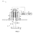
FIG. 2 is a diagrammatical view of a suction valve assembly of a piston machine having an electromagnetic valve actuating system in accordance with an exemplary embodiment of the present invention; -
FIG. 3 is a diagrammatical view of a suction valve assembly of a piston machine having an electromagnetic valve actuating system with stator core and coils disposed outside a housing in accordance with an exemplary embodiment of the present invention; -
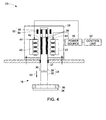
FIG. 4 is a diagrammatical view of a suction valve assembly of a piston machine having an electromagnetic valve actuating system with stator core and coils disposed inside a housing in accordance with an exemplary embodiment of the present invention; and -
FIG. 5 is a diagrammatical view of a suction valve assembly of a piston machine having an electromagnetic valve actuating system with a plurality of permanent magnets having same orientations provided to an anchor plate in accordance with an exemplary embodiment of the present invention. - As discussed in detail below, certain embodiments of the present invention provide a valve operating in a hazardous environment in a machine such as a piston machine having a piston disposed in a housing. It should be noted herein that in some embodiments, the valve is also applicable for use in a high pressure and subatmospheric pressure applications. In certain other embodiments, the valve is also applicable for applications involving preventing leakage of fluid and intrusion of impurities. As used herein, singular forms such as "a," "an," and "the" include plural referents unless the context clearly dictates otherwise. At least one valve is coupled to the housing. The valve includes a movable device disposed partially in the housing. The movable device is coupled to a valve plate. A linear electromagnetic actuator is configured to actuate the valve plate. The actuator includes a set of permanent magnets provided to the movable device and at least one stator core disposed proximate to the movable device with a gap between the stator core and the movable device. In certain embodiments, a control unit is configured to control the supply of electric current to the stator coils based on a load condition of the machine. In some embodiments, the piston machine is a piston compressor. It should be noted herein that the exemplary electromagnetic actuator works like a "stepper motor." The actuator provides constant actuation force along the entire stroke of the piston. Hence better controllability of movement of the valve is achieved. Also, the footprint of the magnetic actuator is substantially smaller than conventional designs.
- Referring generally to
FIG. 1 , in accordance with several aspects of the present embodiment, apiston machine 10 is illustrated. In the illustrated embodiment, the piston machine is acompressor 10 having apiston 12 slidably inserted inside acylinder 14. Asuction valve assembly 16 is provided for opening and closing asuction hole 18 provided at a front side of thepiston 12. Thesuction valve assembly 16 is adapted to control intake of fluid through thesuction hole 18. Thecompressor 10 further includes a linearelectromagnetic actuator 20 adapted to control an opening and closing of thesuction valve assembly 16 during a compression stroke of thecompressor 10 to pressurize the fluid. Acontrol unit 22 may be coupled to theelectromagnetic actuator 20 and configured to control the operation of theelectromagnetic actuator 20. The details of theelectromagnetic actuator 20 are illustrated and explained in greater detail with reference to subsequent embodiments. - It should be noted herein that illustrated configuration of the piston compressor is an exemplary embodiment and should be construed as non-limiting. The piston compressor may additionally include optional exemplary aspects in other embodiments. The reciprocating
compressor 10 may be used for domestic and industrial purposes. Thecompressor 10 is typically driven by an electric motor, steam or gas turbine, combustion engine, or the like. As appreciated by those of ordinary skill in the art, thecompressor 10 may be used to compress air, hydrogen, methane, butane, or other liquids or gases. It should also be noted that theelectromagnetic actuator 20 described herein, is also applicable for other applications including hazardous environment in other machines. - Referring to
FIG. 2 , a linearelectromagnetic actuator 20 adapted to control an opening and closing of thesuction valve assembly 16 is illustrated. Thesuction valve assembly 16 includes amovable device 24 disposed partially in ahousing 26. In the illustrated embodiment, themovable device 24 includes ananchor plate 28 disposed partially in thehousing 26 with aportion 30 of theanchor plate 28 protruding from thehousing 26. Theportion 30 of theanchor plate 28 is coupled to an unloader rod (pushing rod) 32. The pushingrod 32 is coupled to avalve plate 34 movably disposed on avalve seat 36. In other embodiments, the configuration of thevalve plate 34 andvalve seat 36 may vary depending on the application. - In one embodiment, the
housing 26 is a high-pressure housing to facilitate higher actuation force. In another embodiment, thehousing 26 may have thinner walls and may be provided with a high pressure sealing 37 to maintain predetermined pressure within the housing. - In the illustrated embodiment, the
actuator 20 includes a first set ofpermanent magnets 38 having alternating orientations/polarities disposed around theanchor plate 28 within thehousing 26. The number and configuration of the first set ofpermanent magnets 38 may vary depending on the application. A plurality ofstator cores 40 are disposed proximate to theanchor plate 28 with agap 42 between thestator cores 40 and theanchor plate 28. It should be noted herein that in the illustrated embodiment, thehousing 26 is disposed in thegap 42 between thestator cores 40 and theanchor plate 28. A plurality of stator coils 44 are wound to eachstator core 40. It should be noted that the number and configuration of thestator core 40 and the stator coils 44 might vary depending upon the application. Apower source 46 is coupled to the stator coils 44 provided to eachstator core 40 and configured to supply electric current to the stator coils 44. - The
control unit 22 is coupled to thepower source 46 and configured to control the supply of electric current to the stator coils 44 based on a load condition of themachine 10. The opening and closing of thevalve plate 34 is controlled by changing direction of electric current flow through the stator coils 44. In one embodiment, thecontrol unit 22 includes an electronic logic controller that is programmable by a user. Thecontrol unit 22 may control the valve actuator based on the load condition of thecompressor 10. Those of ordinary skill in the art will appreciate in light of the present discussion that any number of compressor constructions are envisaged. - In some embodiments, the
control unit 22 may further include a database, an algorithm, and a data analysis block (not shown). The database may be configured to store predefined information about thecompressor 10. For example, the database may store information relating to crank angle, compressor speed, compressor load, intake fluid pressure, compressed fluid pressure, type of fluid, or the like. The database may also include instruction sets, maps, lookup tables, variables, or the like. Such maps, lookup tables, instruction sets, are operative to correlate characteristics of the valve assembly to specified compressor operation parameters such as compressor speed, crank angle, compressor pressure, compressor load, type of fluid, or the like. Furthermore, the database may be configured to store actual sensed/detected information pertaining to thecompressor 10. The algorithm may facilitate the processing of sensed information pertaining to thecompressor 10. - The data analysis block may include a variety of circuitry types, such as a microprocessor, a programmable logic controller, a logic module or the like. The data analysis block in combination with the algorithm may be used to perform the various computational operations relating to determination of closing time of the suction valves, predetermined time period for controlling opening and closing of the valves, power required to drive the valve, or the like. Any of the above mentioned parameters may be selectively and/or dynamically adapted or altered relative to time.
- The
valve plate 34 is configured to move between a "closed position" and an "open position" to prevent or permit fluid flow respectively. In the illustrated embodiment, thevalve plate 34 is in a closed position i.e. thevalve plate 34 is contacting thevalve seat 36. When thevalve plate 34 is in an open position, the valve plate does not contact thevalve seat 36. Thevalve plate 34 is opened by actuating themovable device 24 downwards against thevalve seat 36. The movement of themovable device 24 is controlled by controlling the supply of electric current through the stator coils 44. When supply of electric current to the stator coils 44 is switched off, thevalve plate 34 is moved to a closed position. When electrical current is supplied to the stator coils 44, thestator core 40 in conjunction with the first set ofpermanent magnets 38 generates an electromagnetic force causing theanchor plate 28 to be pulled downwards. As a result, theunloader rod 32 coupled to theanchor plate 28 is also pushed downward towards thevalve seat 36. As a result of this downward movement (shown by the arrow 50) of themovable device 24, thevalve plate 34 is pushed away from thevalve seat 36 and thevalve plate 34 is opened. As long as the electrical current is supplied to the stator coils 44, the electromagnetic force generated by the actuator 20 biases themovable device 24 against thevalve seat 36, thus maintaining thevalve plate 34 open against a force that is generated by a reverse fluid flow through the valve. - In certain embodiments, the amount of opening and closing of the
valve plate 34 is controlled by controlling direction of supply of electric current through the stator coils 44. In one embodiment, theactuator 20 is used to maintain thevalve plate 34 in an open position for a predetermined period of time. The longer thevalve plate 34 is maintained in an open position during the compression stroke, the more gas that is pushed back into a suction line and the less gas that is delivered to a compressor discharge line. The amount of gas delivered by thecompressor 10 can be controlled by controlling the opening time of thevalve plate 34. - In the illustrated embodiment, a biasing
device 39 is disposed between themovable device 24 and thehousing 26. The biasingdevice 39 is configured to actuate theactuator 20 and bias thevalve plate 34 to a predetermined position (may be opened or closed position) when a power supply to theelectromagnetic actuator 20 is interrupted or turned off. In one embodiment, this ensures that thevalve plate 34 is not in an open position when power supply to theelectromagnetic actuator 20 is cutoff. In the illustrated embodiment, the biasingdevice 39 includes a biasing spring. In other embodiments, other suitable biasing devices are also envisaged. - In certain embodiments, the
electromagnetic valve actuator 20 is employed to control the closing of thesuction valve assembly 16 during the compression stroke of thecompressor 10 at no-load or partial load operating conditions. Although in the illustrated embodiment, onesuction valve assembly 16 is shown, the compressor may include a plurality of suction valves adapted to control the intake of fluid into thecompressor 10. An electromagnetic actuator may be provided for each valve, in order to operate each valve separately and ensure flexibility. For example, depending on the load condition of the compressor, it may be required to vary the closing time of one set of valves from the closing time of the other set valves during compression stroke of the compressor. It should be noted herein that the exemplary valve actuation system is applicable to other valves operating in hazardous environments in machines. - As discussed earlier, the
actuator 20 provides constant actuation force along the stroke of the piston that improves controllability of the movement. There are no electrical components disposed inside the compressor, since thehousing 26 of theactuator 20 is disposed between thestator core 40 and theanchor plate 28, which makes it easier to fulfill safety regulations. Also, cooling of the stator coils 44 is easier since thecoils 44 are disposed outside thehousing 26. The footprint of the actuator design is significantly smaller. Hence, there is no adverse effect on the overall performance of theactuator 20. Moreover, there is limited impact force between themovable device 24 and thestator core 40, since thestator core 40 does not contact themovable device 24. - Referring to
FIG. 3 , a linearelectromagnetic actuator 20 adapted to control an opening and closing of thesuction valve assembly 16 is illustrated. In the illustrated embodiment, the configuration of theactuator 20 is similar to the embodiment illustrated inFIG. 2 , except that a biasingdevice 52 is disposed inside and outside of thehousing 26. The biasingdevice 52 includes a second set ofpermanent magnets 54 disposed outside thehousing 26, and a third set ofpermanent magnets 56 disposed within thehousing 26 around theanchor plate 28. Similar to the previous embodiment, the biasingdevice 52 is configured to actuate theactuator 20 and bias thevalve plate 34 to a predetermined position when a power supply to theelectromagnetic actuator 20 is interrupted or turned off. In other embodiments, other suitable biasing devices are also envisaged. - The
actuator 20 can be actively moved upwards or downwards by the current flow direction through the stator coils 44. The actuation force is constant during the stroke of the piston. Thecoils 44 may be molded using molding material configured to improve heat transfer from thecoils 44 to the ambient. Thecoils 44 do not contact the gas, thereby preventing sparking within the actuator. - Referring to
FIG. 4 , a linearelectromagnetic actuator 20 adapted to control an opening and closing of thesuction valve assembly 16 is illustrated. It should be noted herein that in the illustrated embodiment, the configuration of theactuator 20 is similar to the embodiment illustrated inFIG. 3 ; except that thestator core 40 and stator coils 44 are disposed within thehousing 26. The stator coils 44 and thestator core 40 are disposed inside thehousing 26 thereby reducing the gap between thestator core 40 and theanchor plate 28. This facilitates theactuator 20 to provide higher actuation forces. There is no direct impact between thestator core 40 and theanchor plates 28, resulting in reduced wear and less negative influence on the precision of the device. - Referring to
FIG. 5 , a linearelectromagnetic actuator 20 adapted to control an opening and closing of thesuction valve assembly 16 is illustrated. It should be noted herein that in the illustrated embodiment, the configuration of theactuator 20 is similar to the embodiment illustrated inFIG. 2 ; except that the first set ofpermanent magnets 38 have the same alternating orientations/polarities are disposed around theanchor plate 28 within thehousing 26. A plurality ofiron teeth 58 are disposed between thepermanent magnets 38 having same alternating orientations/polarities. Theactuator 20 of embodiments discussed with reference toFIGS. 1-5 , provides a substantially higher actuation force at the beginning of the piston stroke and constant actuation force for the remaining stroke of the piston. - While only certain features of the invention have been illustrated and described herein, many modifications and changes will occur to those skilled in the art. It is, therefore, to be understood that the appended claims are intended to cover all such modifications and changes as fall within the true spirit of the invention.
Aspects of the present invention are defined in the following numbered clauses: - 1. A valve configured for use in a machine, the valve comprising:
- a movable device disposed partially in a housing;
- a valve plate coupled to the movable device; and
- a linear electromagnetic actuator comprising:
- a first set of permanent magnets provided to the movable device;
- at least one stator core disposed proximate to the movable device with a gap between the stator core and the movable device;
- at least one stator coil wound to each stator core; and
- a power source coupled to the at least one stator coil and configured to supply electric current to the at least one stator coil; wherein opening and closing of the valve plate is controlled by changing direction of electric current flow through the at least one stator coil.
- 2. The valve of clause 1, wherein the valve comprises a suction valve configured for use in a piston compressor.
- 3. The valve of clause 1 or
clause 2, wherein the housing is disposed between the at least one stator core and the movable device. - 4. The valve of any one of the preceding clauses, wherein the at least one stator core, stator coil are disposed in the housing.
- 5. The valve of any one of the preceding clauses, wherein the housing comprises a high pressure housing.
- 6. The valve of any one of the preceding clauses, further comprising a high pressure sealing configured to maintain a predetermined pressure within the housing.
- 7. The valve of any one of the preceding clauses, wherein the first set of permanent magnets have alternating polarities.
- 8. The valve of any one of the preceding clauses, further comprising a plurality of iron teeth disposed between the first set of permanent magnets having same polarities.
- 9. The valve of any one of the preceding clauses, further comprising a biasing device disposed between the movable device and the housing; wherein the biasing device is configured to bias the valve plate to a predetermined position when power supply to the at least one stator coil is interrupted or turned off.
- 10. The valve of clause 9, wherein the biasing device comprises a biasing spring.
- 11. The valve of clause 9, wherein the biasing device comprises a second set of permanent magnets.
- 12. The valve of any one of the preceding clauses, further comprising a biasing device disposed outside the housing; wherein the biasing device is configured to bias the valve plate to a predetermined position when power supply to the at least one stator coil is interrupted or turned off.
- 13. A valve configured for use in a machine, the valve comprising:
- a movable device disposed partially in a housing;
- a valve plate coupled to the movable device; and
- a linear electromagnetic actuator comprising:
- a plurality of permanent magnets provided to the movable device;
- at least one stator core disposed proximate to the movable device with a gap between the stator core and the movable device;
- at least one stator coil wound to each stator core;
- a power source coupled to the at least one stator coil and configured to supply electric current to the at least one stator coil;
- a control unit coupled to the power source and configured to control the supply of electric current to the at least one stator coil based on a load condition of the machine; wherein opening and closing of the valve plate is controlled by changing direction of electric current flow through the at least one stator coil.
- 14. The valve of clause 13, wherein the valve comprises a suction valve configured for use in a piston compressor.
- 15. The valve of clause 13 or
clause 14, wherein the movable device comprises an anchor plate disposed partially within the housing. - 16. The valve of clause 15, wherein the movable device further comprises an unloader rod coupled to the anchor plate.
- 17. The valve of
clause 16, wherein the valve plate is coupled to the unloader rod. - 18. The valve of clause 15, wherein the plurality of permanent magnets are provided to the anchor plate.
- 19. The valve of clause 15, wherein the housing is disposed between the at least one stator core and the anchor plate.
- 20. The valve of any one of clauses 13 to 19, wherein the at least one stator core, stator coil are disposed in the housing.
- 21. A valve configured for use in a machine, the valve comprising:
- a movable device disposed partially in a housing;
- a valve plate coupled to the movable device; and
- a linear electromagnetic actuator comprising:
- a plurality of permanent magnets provided to the movable device;
- at least one stator core disposed proximate to the movable device with a gap between the stator core and the movable device; wherein the housing is disposed in the gap between the stator core and the movable device;
- at least one stator coil wound to each stator core; and
- a power source coupled to the at least one stator coil and configured to supply electric current to the at least one stator coil; wherein opening and closing of the valve plate is controlled by changing direction of electric current flow through the at least one stator coil.
- 22. The valve of clause 21, wherein the plurality of permanent magnets have alternating polarities.
- 23. The valve of clause 21 or
clause 22, further comprising a plurality of iron teeth disposed between the plurality of permanent magnets having same polarities. - 24. The valve of any one of clauses 21 to 23, further comprising a biasing device disposed between the movable device and the housing; wherein the biasing device is configured to bias the valve plate to a predetermined position when power supply to the at least one stator coil is interrupted or turned off.
- 25. The valve of any one of clauses 21 to 24, further comprising a biasing device disposed outside the housing; wherein the biasing device is configured to bias the valve plate to a predetermined position when power supply to the at least one stator coil is interrupted or turned off.
Claims (10)
- A valve configured for use in a machine, the valve comprising:a movable device (24) disposed partially in a housing (26);a valve plate (34) coupled to the movable device (24); anda linear electromagnetic actuator (20) comprising:a first set of permanent magnets (38) provided to the movable device (24);at least one stator core (40) disposed proximate to the movable device (24) with a gap (42) between the stator core (40) and the movable device (24);at least one stator coil (44) wound to each stator core (40); anda power source (46) coupled to the at least one stator coil (44) and configured to supply electric current to the at least one stator coil (44); wherein opening and closing of the valve plate (34) is controlled by changing direction of electric current flow through the at least one stator coil (44).
- The valve of claim 1, wherein the valve comprises a suction valve (16) configured for use in a piston compressor (10).
- The valve of claim 1 or claim 2, wherein the housing (26) is disposed between the at least one stator core (40) and the movable device (24).
- The valve of any one of the preceding claims, further comprising a high pressure sealing (37) configured to maintain a predetermined pressure within the housing (26).
- The valve of any one of the preceding claims, further comprising a plurality of iron teeth (58) disposed between the first set of permanent magnets (38) having same polarities.
- The valve of any one of the preceding claims, further comprising a biasing device (39, 52) disposed between the movable device (24) and the housing (26); wherein the biasing device (39, 52) is configured to bias the valve plate (34) to a predetermined position when power supply to the at least one stator coil (44) is interrupted or turned off.
- The valve of any one of the preceding claims, further comprising a biasing device (39, 52) disposed outside the housing (26); wherein the biasing device (39, 52) is configured to bias the valve plate (34) to a predetermined position when power supply to the at least one stator coil (44) is interrupted or turned off.
- A valve configured for use in a machine, the valve comprising:a movable device (24) disposed partially in a housing (26);a valve plate (34) coupled to the movable device (24); anda linear electromagnetic actuator (20) comprising:a plurality of permanent magnets provided to the movable device (24);at least one stator core (40) disposed proximate to the movable device (24) with a gap (42) between the stator core (40) and the movable device (24);at least one stator coil (44) wound to each stator core (40);a power source (46) coupled to the at least one stator coil (44) and configured to supply electric current to the at least one stator coil (44);a control unit (22) coupled to the power source (46) and configured to control the supply of electric current to the at least one stator coil (44) based on a load condition of the machine; wherein opening and closing of the valve plate (34) is controlled by changing direction of electric current flow through the at least one stator coil (44).
- The valve of claim 8, wherein the movable device (24) comprises an anchor plate (28) disposed partially within the housing (26).
- A valve configured for use in a machine, the valve comprising:a movable device (24) disposed partially in a housing (26);a valve plate (34) coupled to the movable device (24); anda linear electromagnetic actuator (20) comprising:a plurality of permanent magnets provided to the movable device (24);at least one stator core (40) disposed proximate to the movable device (24) with a gap (42) between the stator core (40) and the movable device (24); wherein the housing (26) is disposed in the gap (42) between the stator core (40) and the movable device (24);at least one stator coil (44) wound to each stator core (40); anda power source (46) coupled to the at least one stator coil (44) and configured to supply electric current to the at least one stator coil (44); wherein opening and closing of the valve plate (34) is controlled by changing direction of electric current flow through the at least one stator coil (44).
Applications Claiming Priority (1)
| Application Number | Priority Date | Filing Date | Title |
|---|---|---|---|
| US12/327,842 US20100140519A1 (en) | 2008-12-04 | 2008-12-04 | Electromagnetic actuators |
Publications (3)
| Publication Number | Publication Date |
|---|---|
| EP2194302A2 true EP2194302A2 (en) | 2010-06-09 |
| EP2194302A3 EP2194302A3 (en) | 2010-07-14 |
| EP2194302B1 EP2194302B1 (en) | 2014-03-05 |
Family
ID=41716540
Family Applications (1)
| Application Number | Title | Priority Date | Filing Date |
|---|---|---|---|
| EP09177146.9A Not-in-force EP2194302B1 (en) | 2008-12-04 | 2009-11-26 | Electromagnetic actuators |
Country Status (7)
| Country | Link |
|---|---|
| US (1) | US20100140519A1 (en) |
| EP (1) | EP2194302B1 (en) |
| JP (1) | JP5551922B2 (en) |
| CN (1) | CN101749476B (en) |
| CA (1) | CA2686373C (en) |
| ES (1) | ES2467102T3 (en) |
| RU (1) | RU2548211C2 (en) |
Cited By (3)
| Publication number | Priority date | Publication date | Assignee | Title |
|---|---|---|---|---|
| EP2677217A1 (en) * | 2012-06-20 | 2013-12-25 | Krones AG | Electromagnetic valve for a filling unit of a beverage filling machine |
| GB2564703A (en) * | 2017-07-21 | 2019-01-23 | Weir Group Ip Ltd | Valve |
| US10215295B2 (en) | 2015-05-22 | 2019-02-26 | Nuovo Pignone Tecnologie Srl | Valve for a reciprocating compressor |
Families Citing this family (9)
| Publication number | Priority date | Publication date | Assignee | Title |
|---|---|---|---|---|
| DE102011006071A1 (en) * | 2011-03-24 | 2012-09-27 | Ina - Drives & Mechatronics Gmbh & Co. Ohg | Drive device for a valve, valve for controlling a gas and / or liquid flow |
| EP2515105B1 (en) * | 2011-04-21 | 2019-01-02 | General Electric Company | Gas sensor for measurement of paramagnetic gas component |
| ITCO20110072A1 (en) | 2011-12-22 | 2013-06-23 | Nuovo Pignone Spa | VALVES WITH VALVE VALVE END CONNECTED TO THE ACTUAL COUNTERS AND RELATIVE METHODS |
| ITCO20120023A1 (en) | 2012-05-02 | 2013-11-03 | Nuovo Pignone Srl | ADJUSTMENT OF OPENING TIMES OF A CAM-OPERATED VALVE, ALTERNATIVE COMPRESSOR AND METHOD |
| JP6577830B2 (en) * | 2015-10-28 | 2019-09-18 | 株式会社マキタ | Electric tool |
| DE102018002755A1 (en) * | 2018-04-06 | 2019-10-10 | Peter Rausch | Infinitely variable compressor valve |
| EP3627274B1 (en) * | 2018-09-24 | 2020-10-28 | Siemens Aktiengesellschaft | Fluid pressure control apparatus and system |
| CN112146238A (en) * | 2020-09-26 | 2020-12-29 | 陈雨豪 | Air conditioner temperature controller with intelligent self-adaption function |
| RU204822U1 (en) * | 2020-10-30 | 2021-06-11 | Илья Александрович Новгородов | SILENT VALVE WITH ADDITIONAL MAGNETS |
Citations (5)
| Publication number | Priority date | Publication date | Assignee | Title |
|---|---|---|---|---|
| GB772544A (en) * | 1954-08-19 | 1957-04-17 | Atomic Energy Authority Uk | Improvements in or relating to apparatus for producing pulses in fluids |
| EP0955645A2 (en) * | 1998-05-06 | 1999-11-10 | O.M.T. Officine Meccaniche Torino S.p.A. | Electromagnetic ultraswift actuator without springs |
| CA2240876A1 (en) * | 1998-06-17 | 1999-12-17 | Jack E. Fisher | Fail-safe actuator with two permanent magnets |
| US20060231050A1 (en) * | 2005-04-15 | 2006-10-19 | Lewis Donald J | Adjusting electrically actuated valve lift |
| EP1804259A2 (en) * | 2004-03-26 | 2007-07-04 | Bose Corporation | Electromagnetic actuator and control |
Family Cites Families (29)
| Publication number | Priority date | Publication date | Assignee | Title |
|---|---|---|---|---|
| WO1981001626A1 (en) * | 1979-12-03 | 1981-06-11 | M Gottschall | A two position mechanism |
| JPS57134089A (en) * | 1981-02-13 | 1982-08-19 | Nippon Denso Co Ltd | Flow control valve |
| JPS58140376U (en) * | 1982-03-16 | 1983-09-21 | 太平洋工業株式会社 | proportional control valve |
| US4690371A (en) * | 1985-10-22 | 1987-09-01 | Innovus | Electromagnetic valve with permanent magnet armature |
| JPH0689856B2 (en) * | 1986-01-20 | 1994-11-14 | 松下電器産業株式会社 | Self-holding gas cutoff valve |
| US4794890A (en) * | 1987-03-03 | 1989-01-03 | Magnavox Government And Industrial Electronics Company | Electromagnetic valve actuator |
| SU1663297A1 (en) * | 1988-10-10 | 1991-07-15 | Филиал Всесоюзного Научно-Исследовательского И Проектно-Конструкторского Института Атомного Энергетического Машиностроения | Electromagnetic valve |
| JP2596459B2 (en) * | 1989-03-30 | 1997-04-02 | 株式会社いすゞセラミックス研究所 | Valve electromagnetic drive |
| US5352101A (en) * | 1992-10-05 | 1994-10-04 | Aura Systems, Inc. | Electromagnetically actuated compressor valve |
| DE19601541A1 (en) * | 1995-01-27 | 1996-08-01 | Seiko Seiki Kk | Vacuum chamber with vertical handling system and non-return valve |
| JP3633166B2 (en) * | 1996-12-28 | 2005-03-30 | アイシン・エィ・ダブリュ株式会社 | Linear solenoid |
| JPH11148326A (en) * | 1997-11-12 | 1999-06-02 | Fuji Heavy Ind Ltd | Controller for solenoid valve |
| JPH11287346A (en) * | 1998-04-03 | 1999-10-19 | Ranco Japan Ltd | Solenoid valve |
| US6039014A (en) * | 1998-06-01 | 2000-03-21 | Eaton Corporation | System and method for regenerative electromagnetic engine valve actuation |
| UA67804C2 (en) * | 1998-10-02 | 2004-07-15 | Роналд Нортедж | Valve |
| US7021603B2 (en) * | 1998-10-08 | 2006-04-04 | Wladyslaw Wygnaski | Electromagnetic actuator and integrated actuator and fluid flow control valve |
| US6315265B1 (en) * | 1999-04-14 | 2001-11-13 | Wisconsin Alumni Research Foundation | Variable valve timing actuator |
| DE19922423A1 (en) * | 1999-05-14 | 2000-11-30 | Siemens Ag | Electromechanical actuator |
| JP2002070732A (en) * | 2000-09-01 | 2002-03-08 | Zexel Valeo Climate Control Corp | Variable displacement controller for refrigeration cycle |
| DE10050238A1 (en) * | 2000-10-11 | 2002-04-25 | Bosch Gmbh Robert | Control module for fluid control in injection systems has electromagnetically actuated control valves; magnetic coils are accommodated in apertures in valve body or in insert elements |
| JP4281246B2 (en) * | 2000-12-21 | 2009-06-17 | トヨタ自動車株式会社 | Engine valve drive control device |
| US20030037765A1 (en) * | 2001-08-24 | 2003-02-27 | Shafer Scott F. | Linear control valve for controlling a fuel injector and engine compression release brake actuator and engine using same |
| US7225770B2 (en) * | 2003-12-10 | 2007-06-05 | Borgwarner Inc. | Electromagnetic actuator having inherently decelerating actuation between limits |
| US7032549B1 (en) * | 2004-10-19 | 2006-04-25 | General Motors Corporation | Valve lift sensor |
| UA12621U (en) * | 2005-08-22 | 2006-02-15 | Close Corp Kyiv Central Design | Electro-magnetic valve |
| JP2007056780A (en) * | 2005-08-25 | 2007-03-08 | Daido Steel Co Ltd | Solenoid-operated valve |
| US20070065302A1 (en) * | 2005-09-19 | 2007-03-22 | Schmitz Michael B | System and method for operating a compressor |
| US7651069B2 (en) * | 2006-05-26 | 2010-01-26 | General Electric Company | Electromagnetic actuators |
| RU61835U1 (en) * | 2006-10-10 | 2007-03-10 | Общество с ограниченной ответственностью "Научно-производственная фирма "Микрорэал-Маханов" | GAS VALVE VALVE CONTROLLED PULSE |
-
2008
- 2008-12-04 US US12/327,842 patent/US20100140519A1/en not_active Abandoned
-
2009
- 2009-11-26 EP EP09177146.9A patent/EP2194302B1/en not_active Not-in-force
- 2009-11-26 ES ES09177146.9T patent/ES2467102T3/en active Active
- 2009-11-26 CA CA2686373A patent/CA2686373C/en not_active Expired - Fee Related
- 2009-12-02 JP JP2009274040A patent/JP5551922B2/en not_active Expired - Fee Related
- 2009-12-03 RU RU2009144729/06A patent/RU2548211C2/en not_active IP Right Cessation
- 2009-12-04 CN CN200910253594.6A patent/CN101749476B/en not_active Expired - Fee Related
Patent Citations (5)
| Publication number | Priority date | Publication date | Assignee | Title |
|---|---|---|---|---|
| GB772544A (en) * | 1954-08-19 | 1957-04-17 | Atomic Energy Authority Uk | Improvements in or relating to apparatus for producing pulses in fluids |
| EP0955645A2 (en) * | 1998-05-06 | 1999-11-10 | O.M.T. Officine Meccaniche Torino S.p.A. | Electromagnetic ultraswift actuator without springs |
| CA2240876A1 (en) * | 1998-06-17 | 1999-12-17 | Jack E. Fisher | Fail-safe actuator with two permanent magnets |
| EP1804259A2 (en) * | 2004-03-26 | 2007-07-04 | Bose Corporation | Electromagnetic actuator and control |
| US20060231050A1 (en) * | 2005-04-15 | 2006-10-19 | Lewis Donald J | Adjusting electrically actuated valve lift |
Cited By (5)
| Publication number | Priority date | Publication date | Assignee | Title |
|---|---|---|---|---|
| EP2677217A1 (en) * | 2012-06-20 | 2013-12-25 | Krones AG | Electromagnetic valve for a filling unit of a beverage filling machine |
| CN103511708A (en) * | 2012-06-20 | 2014-01-15 | 克罗内斯股份公司 | Electromagnetic valve for a filling unit of a beverage filling machine |
| CN103511708B (en) * | 2012-06-20 | 2016-03-02 | 克罗内斯股份公司 | For the solenoid valve of the filling mechanism of Beverage filling machine |
| US10215295B2 (en) | 2015-05-22 | 2019-02-26 | Nuovo Pignone Tecnologie Srl | Valve for a reciprocating compressor |
| GB2564703A (en) * | 2017-07-21 | 2019-01-23 | Weir Group Ip Ltd | Valve |
Also Published As
| Publication number | Publication date |
|---|---|
| RU2009144729A (en) | 2011-06-10 |
| JP2010133561A (en) | 2010-06-17 |
| CN101749476B (en) | 2014-07-09 |
| RU2548211C2 (en) | 2015-04-20 |
| EP2194302B1 (en) | 2014-03-05 |
| JP5551922B2 (en) | 2014-07-16 |
| CA2686373A1 (en) | 2010-06-04 |
| US20100140519A1 (en) | 2010-06-10 |
| CN101749476A (en) | 2010-06-23 |
| EP2194302A3 (en) | 2010-07-14 |
| ES2467102T3 (en) | 2014-06-11 |
| CA2686373C (en) | 2017-03-28 |
Similar Documents
| Publication | Publication Date | Title |
|---|---|---|
| EP2194302B1 (en) | Electromagnetic actuators | |
| US20070065302A1 (en) | System and method for operating a compressor | |
| US20170211557A1 (en) | Double-acting refrigeration compressor | |
| KR100608681B1 (en) | Reciprocating compressor | |
| US20070286751A1 (en) | Capacity control of a compressor | |
| KR101624367B1 (en) | Method for controlling the position of an electromechanical actuator for reciprocating compressor valves | |
| US8047166B2 (en) | Electric valve actuation system | |
| JP2012225345A (en) | Reciprocating compressor with delivery rate control | |
| JP2001090659A (en) | Linear compressor | |
| KR20020082854A (en) | Internal combustion engine with exhaust gas control device | |
| CN111336092B (en) | Piston compressor and method of using the same | |
| US4981068A (en) | Expansible chamber device having variably restrained valve systems | |
| KR100239979B1 (en) | Electromagnetically actuated reciprocating compressor driver | |
| KR100660689B1 (en) | Linear compressor | |
| JP2022514735A (en) | Piston compressor | |
| KR100498317B1 (en) | Structure for protecting dead volum of reciprocating compressor | |
| US6790018B2 (en) | Reciprocating compressor having an exhaust valve controlled by an electromagnet | |
| RU2784252C1 (en) | Reciprocating compressor | |
| KR20030005471A (en) | Electo Mechanical valve control device | |
| RU2039879C1 (en) | Engine-pump device | |
| JP2002147209A (en) | Electromagnetic actuator | |
| KR100229331B1 (en) | Piston movement distance control device of a reciprocating compressor | |
| KR20170108375A (en) | Air compressor using permanent-electro magnet | |
| KR20030059613A (en) | Exhaust valve | |
| JP2006002597A (en) | Linear compressor |
Legal Events
| Date | Code | Title | Description |
|---|---|---|---|
| PUAI | Public reference made under article 153(3) epc to a published international application that has entered the european phase |
Free format text: ORIGINAL CODE: 0009012 |
|
| AK | Designated contracting states |
Kind code of ref document: A2 Designated state(s): AT BE BG CH CY CZ DE DK EE ES FI FR GB GR HR HU IE IS IT LI LT LU LV MC MK MT NL NO PL PT RO SE SI SK SM TR |
|
| PUAL | Search report despatched |
Free format text: ORIGINAL CODE: 0009013 |
|
| AK | Designated contracting states |
Kind code of ref document: A3 Designated state(s): AT BE BG CH CY CZ DE DK EE ES FI FR GB GR HR HU IE IS IT LI LT LU LV MC MK MT NL NO PL PT RO SE SI SK SM TR |
|
| RIC1 | Information provided on ipc code assigned before grant |
Ipc: H02K 33/12 20060101ALI20100609BHEP Ipc: F16K 31/08 20060101ALI20100609BHEP Ipc: F16K 31/06 20060101AFI20100504BHEP |
|
| 17P | Request for examination filed |
Effective date: 20110114 |
|
| 17Q | First examination report despatched |
Effective date: 20130107 |
|
| GRAP | Despatch of communication of intention to grant a patent |
Free format text: ORIGINAL CODE: EPIDOSNIGR1 |
|
| INTG | Intention to grant announced |
Effective date: 20130923 |
|
| RIN1 | Information on inventor provided before grant (corrected) |
Inventor name: SCHMITZ, MICHAEL BERNHARD Inventor name: ALI, MOHAMED AHMED Inventor name: KOPECEK, HERBERT |
|
| GRAS | Grant fee paid |
Free format text: ORIGINAL CODE: EPIDOSNIGR3 |
|
| GRAA | (expected) grant |
Free format text: ORIGINAL CODE: 0009210 |
|
| AK | Designated contracting states |
Kind code of ref document: B1 Designated state(s): AT BE BG CH CY CZ DE DK EE ES FI FR GB GR HR HU IE IS IT LI LT LU LV MC MK MT NL NO PL PT RO SE SI SK SM TR |
|
| REG | Reference to a national code |
Ref country code: GB Ref legal event code: FG4D |
|
| REG | Reference to a national code |
Ref country code: CH Ref legal event code: EP |
|
| REG | Reference to a national code |
Ref country code: AT Ref legal event code: REF Ref document number: 655120 Country of ref document: AT Kind code of ref document: T Effective date: 20140315 |
|
| REG | Reference to a national code |
Ref country code: IE Ref legal event code: FG4D |
|
| REG | Reference to a national code |
Ref country code: DE Ref legal event code: R096 Ref document number: 602009022152 Country of ref document: DE Effective date: 20140417 |
|
| REG | Reference to a national code |
Ref country code: NL Ref legal event code: T3 Ref country code: ES Ref legal event code: FG2A Ref document number: 2467102 Country of ref document: ES Kind code of ref document: T3 Effective date: 20140611 |
|
| PG25 | Lapsed in a contracting state [announced via postgrant information from national office to epo] |
Ref country code: LT Free format text: LAPSE BECAUSE OF FAILURE TO SUBMIT A TRANSLATION OF THE DESCRIPTION OR TO PAY THE FEE WITHIN THE PRESCRIBED TIME-LIMIT Effective date: 20140305 Ref country code: NO Free format text: LAPSE BECAUSE OF FAILURE TO SUBMIT A TRANSLATION OF THE DESCRIPTION OR TO PAY THE FEE WITHIN THE PRESCRIBED TIME-LIMIT Effective date: 20140605 |
|
| REG | Reference to a national code |
Ref country code: GR Ref legal event code: EP Ref document number: 20140401044 Country of ref document: GR Effective date: 20140625 |
|
| REG | Reference to a national code |
Ref country code: LT Ref legal event code: MG4D |
|
| PG25 | Lapsed in a contracting state [announced via postgrant information from national office to epo] |
Ref country code: SE Free format text: LAPSE BECAUSE OF FAILURE TO SUBMIT A TRANSLATION OF THE DESCRIPTION OR TO PAY THE FEE WITHIN THE PRESCRIBED TIME-LIMIT Effective date: 20140305 Ref country code: FI Free format text: LAPSE BECAUSE OF FAILURE TO SUBMIT A TRANSLATION OF THE DESCRIPTION OR TO PAY THE FEE WITHIN THE PRESCRIBED TIME-LIMIT Effective date: 20140305 Ref country code: CY Free format text: LAPSE BECAUSE OF FAILURE TO SUBMIT A TRANSLATION OF THE DESCRIPTION OR TO PAY THE FEE WITHIN THE PRESCRIBED TIME-LIMIT Effective date: 20140305 |
|
| PG25 | Lapsed in a contracting state [announced via postgrant information from national office to epo] |
Ref country code: HR Free format text: LAPSE BECAUSE OF FAILURE TO SUBMIT A TRANSLATION OF THE DESCRIPTION OR TO PAY THE FEE WITHIN THE PRESCRIBED TIME-LIMIT Effective date: 20140305 Ref country code: LV Free format text: LAPSE BECAUSE OF FAILURE TO SUBMIT A TRANSLATION OF THE DESCRIPTION OR TO PAY THE FEE WITHIN THE PRESCRIBED TIME-LIMIT Effective date: 20140305 |
|
| PG25 | Lapsed in a contracting state [announced via postgrant information from national office to epo] |
Ref country code: EE Free format text: LAPSE BECAUSE OF FAILURE TO SUBMIT A TRANSLATION OF THE DESCRIPTION OR TO PAY THE FEE WITHIN THE PRESCRIBED TIME-LIMIT Effective date: 20140305 Ref country code: BG Free format text: LAPSE BECAUSE OF FAILURE TO SUBMIT A TRANSLATION OF THE DESCRIPTION OR TO PAY THE FEE WITHIN THE PRESCRIBED TIME-LIMIT Effective date: 20140605 Ref country code: RO Free format text: LAPSE BECAUSE OF FAILURE TO SUBMIT A TRANSLATION OF THE DESCRIPTION OR TO PAY THE FEE WITHIN THE PRESCRIBED TIME-LIMIT Effective date: 20140305 Ref country code: IS Free format text: LAPSE BECAUSE OF FAILURE TO SUBMIT A TRANSLATION OF THE DESCRIPTION OR TO PAY THE FEE WITHIN THE PRESCRIBED TIME-LIMIT Effective date: 20140705 |
|
| PG25 | Lapsed in a contracting state [announced via postgrant information from national office to epo] |
Ref country code: PL Free format text: LAPSE BECAUSE OF FAILURE TO SUBMIT A TRANSLATION OF THE DESCRIPTION OR TO PAY THE FEE WITHIN THE PRESCRIBED TIME-LIMIT Effective date: 20140305 Ref country code: SK Free format text: LAPSE BECAUSE OF FAILURE TO SUBMIT A TRANSLATION OF THE DESCRIPTION OR TO PAY THE FEE WITHIN THE PRESCRIBED TIME-LIMIT Effective date: 20140305 |
|
| REG | Reference to a national code |
Ref country code: DE Ref legal event code: R097 Ref document number: 602009022152 Country of ref document: DE |
|
| PG25 | Lapsed in a contracting state [announced via postgrant information from national office to epo] |
Ref country code: PT Free format text: LAPSE BECAUSE OF FAILURE TO SUBMIT A TRANSLATION OF THE DESCRIPTION OR TO PAY THE FEE WITHIN THE PRESCRIBED TIME-LIMIT Effective date: 20140707 |
|
| PLBE | No opposition filed within time limit |
Free format text: ORIGINAL CODE: 0009261 |
|
| STAA | Information on the status of an ep patent application or granted ep patent |
Free format text: STATUS: NO OPPOSITION FILED WITHIN TIME LIMIT |
|
| PG25 | Lapsed in a contracting state [announced via postgrant information from national office to epo] |
Ref country code: DK Free format text: LAPSE BECAUSE OF FAILURE TO SUBMIT A TRANSLATION OF THE DESCRIPTION OR TO PAY THE FEE WITHIN THE PRESCRIBED TIME-LIMIT Effective date: 20140305 |
|
| 26N | No opposition filed |
Effective date: 20141208 |
|
| REG | Reference to a national code |
Ref country code: DE Ref legal event code: R097 Ref document number: 602009022152 Country of ref document: DE Effective date: 20141208 |
|
| PG25 | Lapsed in a contracting state [announced via postgrant information from national office to epo] |
Ref country code: IT Free format text: LAPSE BECAUSE OF FAILURE TO SUBMIT A TRANSLATION OF THE DESCRIPTION OR TO PAY THE FEE WITHIN THE PRESCRIBED TIME-LIMIT Effective date: 20140305 |
|
| PG25 | Lapsed in a contracting state [announced via postgrant information from national office to epo] |
Ref country code: SI Free format text: LAPSE BECAUSE OF FAILURE TO SUBMIT A TRANSLATION OF THE DESCRIPTION OR TO PAY THE FEE WITHIN THE PRESCRIBED TIME-LIMIT Effective date: 20140305 |
|
| PG25 | Lapsed in a contracting state [announced via postgrant information from national office to epo] |
Ref country code: LU Free format text: LAPSE BECAUSE OF FAILURE TO SUBMIT A TRANSLATION OF THE DESCRIPTION OR TO PAY THE FEE WITHIN THE PRESCRIBED TIME-LIMIT Effective date: 20141126 Ref country code: MC Free format text: LAPSE BECAUSE OF FAILURE TO SUBMIT A TRANSLATION OF THE DESCRIPTION OR TO PAY THE FEE WITHIN THE PRESCRIBED TIME-LIMIT Effective date: 20140305 |
|
| REG | Reference to a national code |
Ref country code: IE Ref legal event code: MM4A |
|
| PG25 | Lapsed in a contracting state [announced via postgrant information from national office to epo] |
Ref country code: IE Free format text: LAPSE BECAUSE OF NON-PAYMENT OF DUE FEES Effective date: 20141126 |
|
| REG | Reference to a national code |
Ref country code: FR Ref legal event code: PLFP Year of fee payment: 7 |
|
| PG25 | Lapsed in a contracting state [announced via postgrant information from national office to epo] |
Ref country code: SM Free format text: LAPSE BECAUSE OF FAILURE TO SUBMIT A TRANSLATION OF THE DESCRIPTION OR TO PAY THE FEE WITHIN THE PRESCRIBED TIME-LIMIT Effective date: 20140305 |
|
| PG25 | Lapsed in a contracting state [announced via postgrant information from national office to epo] |
Ref country code: MT Free format text: LAPSE BECAUSE OF FAILURE TO SUBMIT A TRANSLATION OF THE DESCRIPTION OR TO PAY THE FEE WITHIN THE PRESCRIBED TIME-LIMIT Effective date: 20140305 Ref country code: HU Free format text: LAPSE BECAUSE OF FAILURE TO SUBMIT A TRANSLATION OF THE DESCRIPTION OR TO PAY THE FEE WITHIN THE PRESCRIBED TIME-LIMIT; INVALID AB INITIO Effective date: 20091126 |
|
| REG | Reference to a national code |
Ref country code: FR Ref legal event code: PLFP Year of fee payment: 8 |
|
| PGFP | Annual fee paid to national office [announced via postgrant information from national office to epo] |
Ref country code: NL Payment date: 20161126 Year of fee payment: 8 Ref country code: CZ Payment date: 20161111 Year of fee payment: 8 Ref country code: GB Payment date: 20161128 Year of fee payment: 8 Ref country code: FR Payment date: 20161123 Year of fee payment: 8 |
|
| PGFP | Annual fee paid to national office [announced via postgrant information from national office to epo] |
Ref country code: GR Payment date: 20161128 Year of fee payment: 8 Ref country code: ES Payment date: 20161128 Year of fee payment: 8 Ref country code: BE Payment date: 20161128 Year of fee payment: 8 |
|
| PGFP | Annual fee paid to national office [announced via postgrant information from national office to epo] |
Ref country code: TR Payment date: 20161107 Year of fee payment: 8 |
|
| PG25 | Lapsed in a contracting state [announced via postgrant information from national office to epo] |
Ref country code: MK Free format text: LAPSE BECAUSE OF FAILURE TO SUBMIT A TRANSLATION OF THE DESCRIPTION OR TO PAY THE FEE WITHIN THE PRESCRIBED TIME-LIMIT Effective date: 20140305 |
|
| REG | Reference to a national code |
Ref country code: NL Ref legal event code: MM Effective date: 20171201 |
|
| GBPC | Gb: european patent ceased through non-payment of renewal fee |
Effective date: 20171126 |
|
| PG25 | Lapsed in a contracting state [announced via postgrant information from national office to epo] |
Ref country code: CZ Free format text: LAPSE BECAUSE OF NON-PAYMENT OF DUE FEES Effective date: 20171126 |
|
| PG25 | Lapsed in a contracting state [announced via postgrant information from national office to epo] |
Ref country code: GR Free format text: LAPSE BECAUSE OF NON-PAYMENT OF DUE FEES Effective date: 20180604 |
|
| REG | Reference to a national code |
Ref country code: FR Ref legal event code: ST Effective date: 20180731 Ref country code: BE Ref legal event code: MM Effective date: 20171130 |
|
| PG25 | Lapsed in a contracting state [announced via postgrant information from national office to epo] |
Ref country code: NL Free format text: LAPSE BECAUSE OF NON-PAYMENT OF DUE FEES Effective date: 20171201 Ref country code: FR Free format text: LAPSE BECAUSE OF NON-PAYMENT OF DUE FEES Effective date: 20171130 |
|
| PG25 | Lapsed in a contracting state [announced via postgrant information from national office to epo] |
Ref country code: GB Free format text: LAPSE BECAUSE OF NON-PAYMENT OF DUE FEES Effective date: 20171126 Ref country code: BE Free format text: LAPSE BECAUSE OF NON-PAYMENT OF DUE FEES Effective date: 20171130 |
|
| PG25 | Lapsed in a contracting state [announced via postgrant information from national office to epo] |
Ref country code: ES Free format text: LAPSE BECAUSE OF NON-PAYMENT OF DUE FEES Effective date: 20171127 |
|
| PGFP | Annual fee paid to national office [announced via postgrant information from national office to epo] |
Ref country code: DE Payment date: 20191021 Year of fee payment: 11 |
|
| PGFP | Annual fee paid to national office [announced via postgrant information from national office to epo] |
Ref country code: CH Payment date: 20191022 Year of fee payment: 11 Ref country code: AT Payment date: 20191023 Year of fee payment: 11 |
|
| REG | Reference to a national code |
Ref country code: DE Ref legal event code: R119 Ref document number: 602009022152 Country of ref document: DE |
|
| REG | Reference to a national code |
Ref country code: CH Ref legal event code: PL |
|
| REG | Reference to a national code |
Ref country code: AT Ref legal event code: MM01 Ref document number: 655120 Country of ref document: AT Kind code of ref document: T Effective date: 20201126 |
|
| PG25 | Lapsed in a contracting state [announced via postgrant information from national office to epo] |
Ref country code: CH Free format text: LAPSE BECAUSE OF NON-PAYMENT OF DUE FEES Effective date: 20201130 Ref country code: AT Free format text: LAPSE BECAUSE OF NON-PAYMENT OF DUE FEES Effective date: 20201126 Ref country code: LI Free format text: LAPSE BECAUSE OF NON-PAYMENT OF DUE FEES Effective date: 20201130 |
|
| PG25 | Lapsed in a contracting state [announced via postgrant information from national office to epo] |
Ref country code: DE Free format text: LAPSE BECAUSE OF NON-PAYMENT OF DUE FEES Effective date: 20210601 |
|
| PG25 | Lapsed in a contracting state [announced via postgrant information from national office to epo] |
Ref country code: TR Free format text: LAPSE BECAUSE OF NON-PAYMENT OF DUE FEES Effective date: 20171126 |