EP2194247A2 - System zum Wärmeschutz und zur Abschwächung von Vibrationen und Akustik - Google Patents
System zum Wärmeschutz und zur Abschwächung von Vibrationen und Akustik Download PDFInfo
- Publication number
- EP2194247A2 EP2194247A2 EP09177850A EP09177850A EP2194247A2 EP 2194247 A2 EP2194247 A2 EP 2194247A2 EP 09177850 A EP09177850 A EP 09177850A EP 09177850 A EP09177850 A EP 09177850A EP 2194247 A2 EP2194247 A2 EP 2194247A2
- Authority
- EP
- European Patent Office
- Prior art keywords
- shield
- sump
- layer
- combinations
- protective shield
- Prior art date
- Legal status (The legal status is an assumption and is not a legal conclusion. Google has not performed a legal analysis and makes no representation as to the accuracy of the status listed.)
- Withdrawn
Links
Images



Classifications
-
- F—MECHANICAL ENGINEERING; LIGHTING; HEATING; WEAPONS; BLASTING
- F01—MACHINES OR ENGINES IN GENERAL; ENGINE PLANTS IN GENERAL; STEAM ENGINES
- F01M—LUBRICATING OF MACHINES OR ENGINES IN GENERAL; LUBRICATING INTERNAL COMBUSTION ENGINES; CRANKCASE VENTILATING
- F01M11/00—Component parts, details or accessories, not provided for in, or of interest apart from, groups F01M1/00 - F01M9/00
- F01M11/0004—Oilsumps
-
- F—MECHANICAL ENGINEERING; LIGHTING; HEATING; WEAPONS; BLASTING
- F01—MACHINES OR ENGINES IN GENERAL; ENGINE PLANTS IN GENERAL; STEAM ENGINES
- F01M—LUBRICATING OF MACHINES OR ENGINES IN GENERAL; LUBRICATING INTERNAL COMBUSTION ENGINES; CRANKCASE VENTILATING
- F01M11/00—Component parts, details or accessories, not provided for in, or of interest apart from, groups F01M1/00 - F01M9/00
- F01M11/0004—Oilsumps
- F01M2011/0008—Oilsumps with means for reducing vibrations
- F01M2011/0012—Oilsumps with means for reducing vibrations with acoustic insulation
-
- F—MECHANICAL ENGINEERING; LIGHTING; HEATING; WEAPONS; BLASTING
- F01—MACHINES OR ENGINES IN GENERAL; ENGINE PLANTS IN GENERAL; STEAM ENGINES
- F01M—LUBRICATING OF MACHINES OR ENGINES IN GENERAL; LUBRICATING INTERNAL COMBUSTION ENGINES; CRANKCASE VENTILATING
- F01M11/00—Component parts, details or accessories, not provided for in, or of interest apart from, groups F01M1/00 - F01M9/00
- F01M11/0004—Oilsumps
- F01M2011/0016—Oilsumps with thermic insulation
-
- Y—GENERAL TAGGING OF NEW TECHNOLOGICAL DEVELOPMENTS; GENERAL TAGGING OF CROSS-SECTIONAL TECHNOLOGIES SPANNING OVER SEVERAL SECTIONS OF THE IPC; TECHNICAL SUBJECTS COVERED BY FORMER USPC CROSS-REFERENCE ART COLLECTIONS [XRACs] AND DIGESTS
- Y10—TECHNICAL SUBJECTS COVERED BY FORMER USPC
- Y10T—TECHNICAL SUBJECTS COVERED BY FORMER US CLASSIFICATION
- Y10T428/00—Stock material or miscellaneous articles
- Y10T428/249921—Web or sheet containing structurally defined element or component
- Y10T428/249953—Composite having voids in a component [e.g., porous, cellular, etc.]
-
- Y—GENERAL TAGGING OF NEW TECHNOLOGICAL DEVELOPMENTS; GENERAL TAGGING OF CROSS-SECTIONAL TECHNOLOGIES SPANNING OVER SEVERAL SECTIONS OF THE IPC; TECHNICAL SUBJECTS COVERED BY FORMER USPC CROSS-REFERENCE ART COLLECTIONS [XRACs] AND DIGESTS
- Y10—TECHNICAL SUBJECTS COVERED BY FORMER USPC
- Y10T—TECHNICAL SUBJECTS COVERED BY FORMER US CLASSIFICATION
- Y10T428/00—Stock material or miscellaneous articles
- Y10T428/249921—Web or sheet containing structurally defined element or component
- Y10T428/249953—Composite having voids in a component [e.g., porous, cellular, etc.]
- Y10T428/249987—With nonvoid component of specified composition
- Y10T428/24999—Inorganic
Definitions
- the invention relates generally to a protective shield, and more particularly to a protective shield for thermal protection and damping of vibrations and acoustics of a device, for example, a sump in an aircraft engine.
- Reciprocating engines use either a wet-sump or dry-sump oil system.
- the sump is an enclosure containing bearings and lubrication oil.
- the oil In a dry-sump system, the oil is contained in a separate tank, and circulated through an engine using pumps. In a wet-sump system, the oil is contained in a sump, which is an integral part of the engine.
- the main component of a wet-sump system is an oil pump, in which oil pump draws oil from a sump and routes it to an engine. The oil is routed to the sump after passing through the engine. In some engines, additional lubrication is provided by a rotating crankshaft, in which crankshaft splashes oil onto portions of the engine.
- an oil pump provides oil pressure, but the source of the oil is a separate oil tank, located external to an engine. After oil is routed through the engine, it is pumped from the various locations in the engine back to the oil tank using scavenge pumps.
- the flash point of the lubrication oil in a sump is typically around 400 degrees Fahrenheit.
- the air outside the sump in an aircraft engine can reach temperatures around about 700 degrees Fahrenheit, significantly higher than the flash point of the lubrication oil.
- Cooling air from one or more compressor stages may be circulated around the sump to maintain the temperature of the sump lower than the flash point of the lubrication oil.
- the temperature of the air that is fed from the compressor stages also increases making it difficult to cool the sump.
- a protective shield for a device exposed to heat includes a granular fill layer, a nano particle layer, a metallic foam layer, a thermal barrier coating, or combinations thereof.
- the shield is configured for providing thermal resistance, and damping of vibrations, and acoustics to the device.
- a sump having a protective shield disposed around an outer surface of an enclosure configured to contain lubrication oil is disclosed.
- a protective shield for a sump configured to contain lubrication oil.
- the shield includes a nano particle layer provided on an outer surface of the sump.
- a protective shield for a sump configured to contain lubrication oil.
- the shield includes a metallic foam layer provided on an outer surface of the sump.
- a protective shield for a sump configured to contain lubrication oil.
- the shield includes a thermal barrier coating provided on an outer surface of the sump.
- a protective shield includes a granular fill layer, or nano particle layer, or a metallic foam layer, or a thermal barrier coating, or combinations thereof.
- a protective shield is also applicable for any other devices where thermal insulation is a concern. The approach involves providing a protective shield around a device, for example, a sump, so as to provide a high thermal resistance, thereby reducing the temperature inside the device.
- An outer side of the sump enclosure is insulated with a shield that includes ultra-low thermal conductivity materials with conductivities that are an order of magnitude lower than traditional insulation materials. This will result in a high thermal resistance in the heat path and lead to a significant reduction in the temperature inside the sump. Additionally the protective shield also provides damping of vibrations and acoustics to the device.
- the engine 10 includes a crankcase 12 with a sump 14 provided in a lower portion thereof.
- the engine 12 may include a race engine, aircraft engine, or the like.
- the engine 10 also includes a cam housing 16 and an oil tank 18 located externally to the crankcase 12.
- the oil tank 18 is typically relatively small and only needs to have sufficient capacity to contain a quantity of oil to be supplied to the crankcase 12 for continuous lubrication of the engine 10.
- the oil tank 18 is coupled to the crankcase 12 by a breather conduit 20.
- the tank 18 is coupled to a pressure pump section 22 of a pump and air separator assembly 24 via a conduit 26.
- the assembly 24 further includes a scavenger pump section 28, and an air separator section 30.
- Oil is returned to the sump 14 from the pressure pump section 22 via a conduit 32.
- Oil including entrained air is fed to the scavenger pump section 28 via a conduit 34.
- the scavenger pump section 28 supplies oil to the air separator 30.
- the air separator 30 is provided with two outlets 36 and 38 for exit of the separated oil and air respectively. Oil flows from the outlet 36 back to oil tank 18 through a conduit 40.
- the separated air flows from the outlet 38 to an inlet 42 of a canister or container 44 via a conduit 41.
- the container 44 is provided with a vent 46 for venting the container 44 to the atmosphere.
- the container 44 is also provided with an oil outlet 48 located proximate to a bottom of the container 44. Oil that is condensed out of the separated air in the container 44, may be returned to an inlet 50 of the cam housing 16 via a conduit 52. In the illustrated preferred embodiment, the connection is made on cam housing 14.
- the oil tank 18 is also coupled to an inlet 54 of the container 44 via a conduit 56 provided with a pressure relief valve 58. It should be noted herein that configuration of the engine 10 may vary depending on the application.
- a protective shield 60 is applied to the sump 14.
- the shield 60 is configured to provide a high thermal resistance, thereby reducing the temperature inside the sump 14. Additionally the protective shield 60 also provides damping of vibrations and acoustics to the sump 14. It should be noted that even though the application of the protective shield 60 is discussed with reference to the sump 14 of the engine 10, the shield 60 is equally applicable to other devices where thermal insulation is a matter of concern. The details of the shield 60 are discussed in greater detail with reference to subsequent figures.
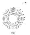
- a protective shield 60 in accordance with an exemplary embodiment of the present invention is illustrated.
- the protective shield 60 is provided around the sump 14.
- the shield 60 includes a layer 62 provided between an outer surface 64 of the sump enclosure 65 and a metallic casing 66.
- the layer 62 may be a granular fill layer.
- the granular fill layer may include sand, lead shots, steel balls, or the like. Thermal resistance and significant damping of structural vibration can be attained by coupling a low-density medium such as granular particles in which the speed of heat, vibration, and sound propagation is relatively low.
- granular material such as sand can be modeled as a continuum, and that thermal resistance and damping in a structure filled with such a granular material can be increased so that standing waves occur in the granular material at the resonant frequencies of a structure.
- a low-density granular fill material can provide high damping of structural vibration over a broad range of frequencies.
- the layer 62 may be a nano particle layer.
- the nano particle layer may include ceramic particles, polymeric particles, or combinations thereof having relatively low thermal conductivity.
- the ceramic particles include but are not limited to ceramic oxide, ceramic carbide, ceramic nitride, or combinations thereof. Most of these ceramic materials have relatively high melting points (e.g. higher than 1500 degrees Celsius) and hence will be suitable for high temperature applications.
- Ceramic oxide includes silicon oxide, titanium oxide, aluminum oxide, magnesium oxide, yttrium oxide, zirconium oxide, yttrium stabilized zirconium, or combinations thereof. It should be noted herein that material properties at the nano level are different than those at the macro level. For example, in case of carbon nanotubes (CNTs), their axial thermal conductivity is more than an order of magnitude higher than that of bulk carbon.
- CNTs carbon nanotubes
- CNTs which geometry allows for ballistic transport of heat along the axial direction.
- reducing the feature size for a material may cause a reduction in a particular property.
- using nanoparticles in lieu of micron-sized or bigger particles may help decrease the thermal conduction in a system for certain materials.
- one factor affecting the thermal transport in a system of nanoparticles is believed to be the increase in surface area to volume ratio for a nanoparticle compared to a micron-sized or bigger particle. Due to the increased surface area to volume ratio, the nano-particulate system would exhibit comparatively higher resistance to thermal transport. This is caused by the increase in number of interfaces between the particles and the matrix and, among the particles themselves.
- the coating materials may be non-metallic.
- the heat is transported by phonons (analogous to electrons in electrical transport).
- Phonons typically have a large variation in their frequencies and mean-free-paths (mfps).
- mfps mean-free-paths
- the bulk of the heat is carried out by phonons with mfps in the range between about 1 to about 100 nm at room temperature.
- Mean-free-path is defined as the distance a phonon travels before it collides with something else such as the lattice or an impurity. Hence, it has a significant impact on the thermal conduction through them.
- a low temperature liquid assisted, spray process is used to deposit nano particles on the surface of the sump enclosure.
- the nano particle layer might be formed by various techniques including liquid phase wetting, chemical vapor deposition, sintering, annealing, or combinations thereof.
- the thermal resistance along the metallic casing 66 is relatively lower than across the layer 62 into the sump 14.
- the metallic casing 66 may include but is not limited to iron, titanium, copper, zirconium, aluminum, and nickel. As a result heat conducts slower across the layer 62 compared to that along the metallic casing 66, thereby creating an effective thermal shield.
- the layer 62 also facilitates damping of vibrations and acoustics of the sump 14.
- the shield 60 may further include a super hydrophilic coating 68 provided on the metallic casing 66.
- the formation of the super hydrophilic coating 68 facilitates the formation of a water film on a surface of the coating 68 resulting in improved thermal resistance.
- the super hydrophilic coating 68 may be formed by various techniques including but not limited to texturing, grinding, shot peening, micromachining, grid blasting, coating, or combinations thereof.
- the shield 60 may also additionally include an oleophilic coating 70 provided on an inner surface 72 of the sump 14. The formation of the oleophilic coating 70 facilitates formation of an oil film on a surface of the coating 70 thereby further improving the thermal resistance.
- the shield 60 may not include the metallic casing 66.
- the layer 62 may be formed on the outer surface 64 of the sump 14 and the super hydrophilic coating 68 may be provided on a surface of the layer 62.
- the nanoparticles are bound together only by Van der Waals interaction. Such nano structure can be sintered or annealed to induce necking or diffusion of materials at the contacts between the particles to improve the mechanical strength of the nano porous structures.
- a protective shield 74 in accordance with an exemplary embodiment of the present invention is illustrated.
- the protective shield 74 is provided around the sump 14.
- the shield 74 includes a metallic foam layer 76 provided on the outer surface 64 of the sump enclosure 65. Thermal resistance and significant damping of structural vibration can be attained by coupling a low-density medium such as foam in which the speed of heat, vibration, and sound propagation is relatively low. The effective thermal conductivity is reduced due to the trapped air inside the foam layer 76.
- the metallic foam layer 76 may be disposed between the outer surface 64 of the sump enclosure 65 and the metallic casing 66 (illustrated in FIG. 2 ).
- the shield 60 may further include the super hydrophilic coating 68 (illustrated in FIG. 2 ) provided on the metallic casing.
- the shield 60 may not include the metallic casing 66.
- the super hydrophilic coating 68 may be provided on a surface of the metallic foam layer 76.
- the shield 75 includes a thermal barrier coating 78 applied on the outer surface 64 of the sump enclosure 65 via a thermally grown oxide layer 80.
- Thermal barrier coating 78 such as ceramic coating is characterized by its low thermal conductivity. It should be noted herein that when the thermal barrier coating is applied to a surface of a component, thermal barrier coating induce a large temperature gradient as it is exposed to heat flow.
- the thermal barrier coating 78 includes a yittria stabilized zirconium layer having a thickness of about 300 micro meters applied using a thermal spray process.
- the thermally grown oxide layer 80 provides oxidation resistance to the thermal barrier coating 78.
- the thermal barrier coating 78 is formed by electron beam physical vapor deposition and may have thickness of about 120 micrometers.
- the electron beam physical vapor deposition technique involves heating an ingot of a coating material in a crucible and vaporized using a high power electron beam. The vapor deposits on a substrate surface rotatable above the vapor source.
- the thermal barrier coating 78 includes functionally graded materials. It should be noted herein that the concept of functionally graded materials is to create spatial variations in composition and/or microstructure that result in corresponding changes in material properties. By varying the composition of the thermal barrier coating 78 during the deposition process, the thermal barrier coating 78 that offers the desired thermal and mechanical properties at the coating surface can be deposited, while having an optimum thermal expansion match with the base material at the interface.
- the shield 81 includes a plurality of metallic insulation layers 82, 84, 86 disposed around the outer surface 64 of the sump enclosure 65. Even though 3 metallic insulation layers are illustrated in the embodiment, the number of metallic insulation layers may vary in other embodiments depending upon the application.
- the layer 62 (granular fill layer or nano particle layer) is disposed between the outer surface 64 of the sump enclosure 65 and the metallic insulation layer 82.
- the metallic foam layer 76 is disposed between the metallic insulation layers 82, 84.
- the thermal barrier coating 78 is disposed between the metallic insulation layers 84, 86.
Landscapes
- Engineering & Computer Science (AREA)
- Mechanical Engineering (AREA)
- General Engineering & Computer Science (AREA)
- Laminated Bodies (AREA)
- Other Surface Treatments For Metallic Materials (AREA)
- Exhaust Silencers (AREA)
- Building Environments (AREA)
- Lubrication Details And Ventilation Of Internal Combustion Engines (AREA)
Applications Claiming Priority (1)
| Application Number | Priority Date | Filing Date | Title |
|---|---|---|---|
| US12/326,920 US20100136323A1 (en) | 2008-12-03 | 2008-12-03 | System for thermal protection and damping of vibrations and acoustics |
Publications (2)
| Publication Number | Publication Date |
|---|---|
| EP2194247A2 true EP2194247A2 (de) | 2010-06-09 |
| EP2194247A3 EP2194247A3 (de) | 2012-06-20 |
Family
ID=42035897
Family Applications (1)
| Application Number | Title | Priority Date | Filing Date |
|---|---|---|---|
| EP20090177850 Withdrawn EP2194247A3 (de) | 2008-12-03 | 2009-12-03 | System zum Wärmeschutz und zur Abschwächung von Vibrationen und Akustik |
Country Status (4)
| Country | Link |
|---|---|
| US (1) | US20100136323A1 (de) |
| EP (1) | EP2194247A3 (de) |
| JP (1) | JP2010133407A (de) |
| CA (1) | CA2686004A1 (de) |
Cited By (2)
| Publication number | Priority date | Publication date | Assignee | Title |
|---|---|---|---|---|
| CN104019328A (zh) * | 2014-05-14 | 2014-09-03 | 安徽盛华管业有限公司 | 一种防冻pvc管 |
| US9463859B1 (en) | 2015-02-13 | 2016-10-11 | Brunswick Corporation | Adapter plate, heat shield, and method for thermally isolating a mount coupled to an adapter plate |
Families Citing this family (6)
| Publication number | Priority date | Publication date | Assignee | Title |
|---|---|---|---|---|
| EP2971608B1 (de) * | 2013-03-15 | 2020-06-10 | United Technologies Corporation | Gasturbinenmotor und verfahren zur herstellung |
| US20150321289A1 (en) * | 2014-05-12 | 2015-11-12 | Siemens Energy, Inc. | Laser deposition of metal foam |
| CN104373771A (zh) * | 2014-10-31 | 2015-02-25 | 无锡同心塑料制品有限公司 | 一种具有纳米层的保温管道 |
| CN105114762A (zh) * | 2015-09-12 | 2015-12-02 | 泰州市鑫润天冶金保温材料有限公司 | 一种纳米孔硅绝热板 |
| US10113483B2 (en) | 2016-02-23 | 2018-10-30 | General Electric Company | Sump housing for a gas turbine engine |
| US9657387B1 (en) * | 2016-04-28 | 2017-05-23 | General Electric Company | Methods of forming a multilayer thermal barrier coating system |
Family Cites Families (19)
| Publication number | Priority date | Publication date | Assignee | Title |
|---|---|---|---|---|
| AT265755B (de) * | 1966-01-10 | 1968-10-25 | H C Hans Dipl Ing Dr Dr List | Brennkraftmaschine mit auf einem Geräteträger angebrachten motorgeriebenen Hilfsaggregaten |
| US3398873A (en) * | 1966-09-07 | 1968-08-27 | Hollis Engineering | Sumps and nozzles for soldering machines |
| JPS63290732A (ja) * | 1987-05-25 | 1988-11-28 | Yoshio Niioka | 複合材 |
| US5775049A (en) * | 1995-06-14 | 1998-07-07 | Fricke; J. Robert | Method and apparatus for damping structural vibrations |
| US5820348A (en) * | 1996-09-17 | 1998-10-13 | Fricke; J. Robert | Damping system for vibrating members |
| US6435660B1 (en) * | 1999-10-05 | 2002-08-20 | Canon Kabushiki Kaisha | Ink jet recording head substrate, ink jet recording head, ink jet recording unit, and ink jet recording apparatus |
| US6890640B2 (en) * | 1999-12-03 | 2005-05-10 | Caterpillar Inc | Patterned hydrophilic-oleophilic metal oxide coating and method of forming |
| JP2001205399A (ja) * | 2000-01-25 | 2001-07-31 | Nippon Steel Corp | 双ドラム式薄鋳片連続鋳造用冷却ドラム及び連続鋳造方法 |
| JP4040486B2 (ja) * | 2003-02-10 | 2008-01-30 | トヨタ自動車株式会社 | 発泡樹脂製オイルパン及びその製造方法 |
| US7585559B2 (en) * | 2003-06-03 | 2009-09-08 | Intellectual Property Holdings, Llc | Foam barrier heat shield |
| US6875529B1 (en) * | 2003-12-30 | 2005-04-05 | General Electric Company | Thermal barrier coatings with protective outer layer for improved impact and erosion resistance |
| JP4364654B2 (ja) * | 2004-01-21 | 2009-11-18 | 四国建設株式会社 | 建築物の外断熱構造 |
| US7367304B2 (en) * | 2005-02-01 | 2008-05-06 | Gm Global Technology Operations, Inc. | Apparatus and method for forced response acoustic isolation enclosure in cast aluminum oil pan |
| US20070022732A1 (en) * | 2005-06-22 | 2007-02-01 | General Electric Company | Methods and apparatus for operating gas turbine engines |
| US7402277B2 (en) * | 2006-02-07 | 2008-07-22 | Exxonmobil Research And Engineering Company | Method of forming metal foams by cold spray technique |
| WO2007121556A1 (en) * | 2006-04-25 | 2007-11-01 | National Research Counsil Of Canada | Thermal spray coating of porous nanostructured ceramic feedstock |
| US8236379B2 (en) * | 2007-04-02 | 2012-08-07 | Applied Microstructures, Inc. | Articles with super-hydrophobic and-or super-hydrophilic surfaces and method of formation |
| DE102008025795A1 (de) * | 2007-06-01 | 2008-12-04 | Ostermann, Dieter, Dr. | Abgaswärmetauscher |
| US20110297358A1 (en) * | 2010-06-07 | 2011-12-08 | The Boeing Company | Nano-coating thermal barrier and method for making the same |
-
2008
- 2008-12-03 US US12/326,920 patent/US20100136323A1/en not_active Abandoned
-
2009
- 2009-11-19 CA CA 2686004 patent/CA2686004A1/en not_active Abandoned
- 2009-12-01 JP JP2009273091A patent/JP2010133407A/ja not_active Withdrawn
- 2009-12-03 EP EP20090177850 patent/EP2194247A3/de not_active Withdrawn
Cited By (2)
| Publication number | Priority date | Publication date | Assignee | Title |
|---|---|---|---|---|
| CN104019328A (zh) * | 2014-05-14 | 2014-09-03 | 安徽盛华管业有限公司 | 一种防冻pvc管 |
| US9463859B1 (en) | 2015-02-13 | 2016-10-11 | Brunswick Corporation | Adapter plate, heat shield, and method for thermally isolating a mount coupled to an adapter plate |
Also Published As
| Publication number | Publication date |
|---|---|
| US20100136323A1 (en) | 2010-06-03 |
| EP2194247A3 (de) | 2012-06-20 |
| CA2686004A1 (en) | 2010-06-03 |
| JP2010133407A (ja) | 2010-06-17 |
Similar Documents
| Publication | Publication Date | Title |
|---|---|---|
| EP2194247A2 (de) | System zum Wärmeschutz und zur Abschwächung von Vibrationen und Akustik | |
| US11370717B2 (en) | Protective coating systems for gas turbine engine applications | |
| Zhang et al. | Understanding surface roughness on vertical surfaces of 316 L stainless steel in laser powder bed fusion additive manufacturing | |
| Peters et al. | Design of an integrated loop heat pipe air-cooled heat exchanger for high performance electronics | |
| Che et al. | Spark plasma sintering of titanium-coated diamond and copper–titanium powder to enhance thermal conductivity of diamond/copper composites | |
| EP1373598B1 (de) | Wärmedämmschicht mit unter der oberfläche vorliegenden einschlüssen für verbesserte temperaturwechselbeständigkeit | |
| Chen et al. | Microstructure and anti-oxidation properties of Yb2Si2O7/SiC bilayer coating for C/SiC composites | |
| US10124402B2 (en) | Methods for manufacturing carbon fiber reinforced aluminum composites using stir casting process | |
| US20070089860A1 (en) | Heat pipe with sintered powder wick | |
| WO2005051065A2 (en) | Pumped liquid cooling for computer systems using liquid metal coolant | |
| WO2010080235A1 (en) | Heat exchangers and related methods | |
| Dewar et al. | Interfacial heating during low-pressure cold-gas dynamic spraying of aluminum coatings | |
| Hu et al. | Crack development behavior in thermally sprayed anti-oxidation coating under repeated thermal-oxygen coupling environment | |
| EP2977700A1 (de) | Kühler, kühlvorrichtung damit und verfahren zur kühlung eines wärmeerzeugungselements | |
| Kim et al. | Enhanced nucleate pool boiling heat transfer on CNTs-Cu nanoparticles-coated surfaces: Effects of sintering temperature and CNTs composition on pool boiling behavior | |
| Zou et al. | Influence of SiC content on microstructure and mechanical properties of SiCp/AlSi7Mg composites fabricated by selective laser melting | |
| KR20080087878A (ko) | 내연 기관에서의 액체 냉각 장치 및 액체 냉각 장치의 제조공정 | |
| KR20200122370A (ko) | 차열 코팅, 터빈 부재, 가스 터빈 및 차열 코팅의 제조 방법 | |
| Liu et al. | Microstructure evolution of TiC/Inconel 718 composites prepared by direct energy deposition | |
| JP6209058B2 (ja) | リエントラント形状の冷却チャネルを備えた構成部品および製造方法 | |
| BT et al. | Optimizing process parameters to minimize wear-induced material loss in bronze-based hybrid metal matrix composites using the Taguchi method | |
| WO2021215046A1 (ja) | ステンレス鋼からなる造形用粉末または造形用ワイヤ、またはステンレス鋼からなる積層構造体である造形物 | |
| Zhang et al. | Corrosion resistance of Ti3Al/BN abradable seal coating | |
| Shao et al. | Improvements in the microstructure and wear resistance of cast-iron coating plasma-sprayed with Mo-partially cladded cast iron powder | |
| Bang et al. | Fabrication and analysis of the wear properties of hot-pressed Al-Si/SiCp+ Al-Si-Cu-Mg metal matrix composite |
Legal Events
| Date | Code | Title | Description |
|---|---|---|---|
| PUAI | Public reference made under article 153(3) epc to a published international application that has entered the european phase |
Free format text: ORIGINAL CODE: 0009012 |
|
| AK | Designated contracting states |
Kind code of ref document: A2 Designated state(s): AT BE BG CH CY CZ DE DK EE ES FI FR GB GR HR HU IE IS IT LI LT LU LV MC MK MT NL NO PL PT RO SE SI SK SM TR |
|
| PUAL | Search report despatched |
Free format text: ORIGINAL CODE: 0009013 |
|
| AK | Designated contracting states |
Kind code of ref document: A3 Designated state(s): AT BE BG CH CY CZ DE DK EE ES FI FR GB GR HR HU IE IS IT LI LT LU LV MC MK MT NL NO PL PT RO SE SI SK SM TR |
|
| RIC1 | Information provided on ipc code assigned before grant |
Ipc: F02B 77/08 20060101ALI20120514BHEP Ipc: F01M 11/00 20060101AFI20120514BHEP |
|
| 17P | Request for examination filed |
Effective date: 20121220 |
|
| GRAP | Despatch of communication of intention to grant a patent |
Free format text: ORIGINAL CODE: EPIDOSNIGR1 |
|
| INTG | Intention to grant announced |
Effective date: 20130628 |
|
| STAA | Information on the status of an ep patent application or granted ep patent |
Free format text: STATUS: THE APPLICATION IS DEEMED TO BE WITHDRAWN |
|
| 18D | Application deemed to be withdrawn |
Effective date: 20131109 |