EP2194235A1 - Housing component for an axial turbo engine with passive seam control, gas turbine with the housing component and method for retrofitting an existing housing component - Google Patents
Housing component for an axial turbo engine with passive seam control, gas turbine with the housing component and method for retrofitting an existing housing component Download PDFInfo
- Publication number
- EP2194235A1 EP2194235A1 EP08021217A EP08021217A EP2194235A1 EP 2194235 A1 EP2194235 A1 EP 2194235A1 EP 08021217 A EP08021217 A EP 08021217A EP 08021217 A EP08021217 A EP 08021217A EP 2194235 A1 EP2194235 A1 EP 2194235A1
- Authority
- EP
- European Patent Office
- Prior art keywords
- housing component
- cavity
- axial turbomachine
- axial
- component according
- Prior art date
- Legal status (The legal status is an assumption and is not a legal conclusion. Google has not performed a legal analysis and makes no representation as to the accuracy of the status listed.)
- Withdrawn
Links
Images
Classifications
-
- F—MECHANICAL ENGINEERING; LIGHTING; HEATING; WEAPONS; BLASTING
- F01—MACHINES OR ENGINES IN GENERAL; ENGINE PLANTS IN GENERAL; STEAM ENGINES
- F01D—NON-POSITIVE DISPLACEMENT MACHINES OR ENGINES, e.g. STEAM TURBINES
- F01D11/00—Preventing or minimising internal leakage of working-fluid, e.g. between stages
- F01D11/08—Preventing or minimising internal leakage of working-fluid, e.g. between stages for sealing space between rotor blade tips and stator
- F01D11/14—Adjusting or regulating tip-clearance, i.e. distance between rotor-blade tips and stator casing
- F01D11/16—Adjusting or regulating tip-clearance, i.e. distance between rotor-blade tips and stator casing by self-adjusting means
- F01D11/18—Adjusting or regulating tip-clearance, i.e. distance between rotor-blade tips and stator casing by self-adjusting means using stator or rotor components with predetermined thermal response, e.g. selective insulation, thermal inertia, differential expansion
-
- F—MECHANICAL ENGINEERING; LIGHTING; HEATING; WEAPONS; BLASTING
- F05—INDEXING SCHEMES RELATING TO ENGINES OR PUMPS IN VARIOUS SUBCLASSES OF CLASSES F01-F04
- F05D—INDEXING SCHEME FOR ASPECTS RELATING TO NON-POSITIVE-DISPLACEMENT MACHINES OR ENGINES, GAS-TURBINES OR JET-PROPULSION PLANTS
- F05D2300/00—Materials; Properties thereof
- F05D2300/50—Intrinsic material properties or characteristics
- F05D2300/502—Thermal properties
- F05D2300/5021—Expansivity
- F05D2300/50211—Expansivity similar
Definitions
- the invention relates to a housing component for an axial turbomachine with passive gap control, a gas turbine with the housing component and a method for retrofitting an existing housing component for an axial turbomachine with a device for passive gap control.
- radial gaps between blades and the housing lead to significant losses in thermal efficiency.
- the axial turbomachine is, for example, a gas turbine.
- the gas turbine When starting and stopping the gas turbine, the radial gaps change over time.
- the radial gaps change when switching from part load operation to full load operation of the gas turbine.
- the gas turbine is designed so that the radial gap for the operating case in which the radial gaps are the smallest set, are sufficiently large, so that there is virtually no contact between the blades and the housing. This has the consequence that in continuous operation of the gas turbine unnecessarily large radial gaps must be kept for this operating condition, which is associated with a significant loss of efficiency.
- the temporal change of the radial gaps is the result of different thermal inertia behavior of the individual components of the gas turbine, in particular rotor and housing.
- the temporal change of the radial gap caused the centrifugal force, in particular of the blades, a transverse contraction of the rotor, a possible Game in the thrust bearing of the rotor, in particular in connection with the reversal of axial thrust under appropriate operating conditions of the gas turbine, a possibly occurring ovalization of the housing due to assembly-related bias and uneven heating of the housing.
- the object of the invention is to provide a housing component for an axial turbomachine, a gas turbine with the housing component and a method for retrofitting an existing housing component for an axial turbomachine, wherein the axial turbomachine and the gas turbine have a high thermal efficiency.
- the axial turbomachine housing component of the present invention includes a wall portion having an outer annular surface defining a hub contour of a main flow passage of the axial turbomachine and, when the housing component is mounted in the axial turbomachine, immediately adjacent to and formed within the freestanding blade tips of vanes of vanes Radial gaps are arranged, and a closed cavity, which is arranged radially inside and in the axial portion of the blade tips and filled with a compensation material, the melting temperature is selected such that when starting and / or when driving the axial turbomachine, the compensation material undergoes a phase transition, whereby the thermal expansion rate of the housing component at the outer annular surface is approximated to that of the blade tips.
- the melting temperature of the compensation material is selected such that when starting and / or when driving off the axial turbomachine, the compensating material undergoes the phase transition, heat is absorbed or released by the compensating material when starting and / or when driving off the axial turbomachine.
- a heating of the housing component is delayed, whereby the thermal expansion rate of the housing component is reduced.
- the thermal expansion rate at the blade tip is lower than at the outer ring surface of the housing component, so that the radial gap would have to be kept correspondingly large in order to prevent the blade tip from touching the outer ring surface during operation of the axial turbomachine.
- Due to the retarding effect on the expansion rate of the housing component caused by the phase transition of the compensation material the expansion velocities of the housing component are aligned on the outer ring surface and the blade tip, so that the radial gap can be provided as small, yet the axial turbomachine is safe to operate.
- the radial gap can advantageously be reduced during stationary operation of the axial turbomachine according to the invention compared to a conventional axial turbomachine.
- the onrip problem is reduced when starting hot.
- a fine adjustment of the radial gap is conceivable by a correspondingly suitable selection of the compensation materials.
- the compensation material learns preferably when starting the axial turbomachine the phase transition from solid to liquid, whereby a heating of the housing component is delayed, and / or the phase transition from liquid to solid during shutdown, whereby a cooling of the housing component is delayed.
- the cavity preferably has a sealed opening through which, when it is open, the compensation material can be filled.
- the opening is preferably welded closed and / or screwed with a screw plug and / or closed with a lid.
- the cavity is designed as an annular space surrounding the axis of the axial turbomachine.
- the housing component is preferably formed by a cast construction.
- the cavity is preferably produced by means of a casting core.
- the housing component is formed by a sheet metal construction.
- the cavity is preferably formed in the sheet metal construction with a double shell.
- the cavity is made by material removal, in particular drilling, turning or milling.
- the cavity is formed by a venting channel provided in the housing component and / or an internal cavity of a hollow strut.
- the gas turbine according to the invention has the housing component.
- the inventive method for retrofitting an existing housing component for an axial turbomachine with a passive gap control device comprises the step of providing the existing housing component having a wall portion having an outer annular surface defining a hub contour of a main flow channel of the axial turbomachine and if the housing component is mounted in the axial turbomachine on which freestanding blade tips of vanes of vanes are disposed immediately adjacent and forming a radial gap; Finishing a cavity in the housing component, wherein the cavity is arranged radially inwardly and at the level of the blade tips and having an opening through which the cavity is accessible from the outside, and / or, if the housing component has a vent channel and / or an inner cavity of a hollow strut having, selection of the vent channel and / or the inner cavity for the cavity; Filling a compensation material in the cavity, wherein the melting temperature of the compensation material is selected such that when starting and / or when driving off the axial turbomachine, the compensation material has a phase transition experiences; Closing the opening so that
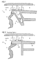
- FIG. 2 shows a conventional axial turbomachine 101 having an outer housing 2.
- On the outer casing 2 are fixed in rings vanes 3, which are delimited radially inwardly each with a blade tip 4.
- a shaft cover 103 is disposed radially inside, which is arranged with its outer ring surface 7 facing the blade tips 4.
- a radial gap 11 is provided in each case.
- a main flow channel 9 of the axial turbomachine 1 is traversed from left to right in a main flow direction 10, wherein the main flow channel 9 is bounded by a hub contour 8 defined by the outer ring surface 7.
- a hub shell 102 Downstream of the shaft cover 103, a hub shell 102 is disposed.
- a rotor disk 5 is arranged, which carries blades in a known manner.
- FIG. 1 an axial turbomachine 1 according to the invention is shown, which compared to the conventional axial turbomachine 101 according to FIG. 2 differs in that the axial turbomachine 1 according to the invention instead of the hub shell 102 and the shaft cover 103 has a housing component 6.
- the housing component 6 has at the blade tips 4 immediately adjacent to the outer annular surface 7, with the blade tip 4 toward the radial gap 11 is defined.
- a cavity 12 is provided in the housing component 6, which has a sealed opening 13 on the outer annular surface 7.
- the cavity 12 is filled with a compensation material 14, wherein the compensation material 14 occupies about one third of the volume of the cavity 12.
- the cavity 12 could also be completely filled.
- the balance material 14 may be lead, zinc or tin.
- the melting temperature of the compensation material 14 is such that when starting the axial turbomachine 1, the compensation material 14 undergoes a phase transition after solid to liquid and when driving the axial turbomachine 1, a phase transition from liquid to solid. During the phase transition from solid to liquid, the compensation material 14 absorbs heat, as a result of which heating of the housing component 6 is delayed. When lowering the axial turbomachine 1, the compensation material 14 undergoes a phase transition from liquid to solid, whereby the compensation material 14 releases heat, whereby a cooling of the housing component 6 is delayed.
- the compensation material 14 was filled into the cavity 12, wherein the operation of the axial turbomachine 1, the opening 13 is sealed so tightly that the compensation material 14 from the cavity 12 can not escape.
Abstract
Description
Die Erfindung betrifft eine Gehäusekomponente für eine Axialturbomaschine mit passiver Spaltkontrolle, eine Gasturbine mit der Gehäusekomponente und ein Verfahren zum Nachrüsten einer bestehenden Gehäusekomponente für eine Axialturbomaschine mit einer Einrichtung zur passiven Spaltkontrolle.The invention relates to a housing component for an axial turbomachine with passive gap control, a gas turbine with the housing component and a method for retrofitting an existing housing component for an axial turbomachine with a device for passive gap control.
In einer Axialturbomaschine führen Radialspalte zwischen Laufschaufeln und dem Gehäuse zu erheblichen Einbußen im thermischen Wirkungsgrad. Um einen möglichst hohen Wirkungsgrad zu erzielen, ist es erstrebenswert, die Radialspalte in allen Betriebspunkten der Axialturbomaschine möglichst klein zu halten. Die Axialturbomaschine ist beispielsweise eine Gasturbine. Beim Anfahren und Abfahren der Gasturbine verändern sich die Radialspalte über die Zeit. Außerdem verändern sich die Radialspalte beim Wechsel vom Teillastbetrieb zum Volllastbetrieb der Gasturbine. Herkömmlich ist die Gasturbine derart ausgelegt, dass die Radialspalte für den Betriebsfall, in dem sich die Radialspalte als am kleinsten einstellen, ausreichend groß dimensioniert sind, so dass es so gut wie zu keiner Berührung zwischen den Laufschaufeln und dem Gehäuse kommt. Dies hat zur Folge, dass im Dauerbetrieb der Gasturbine für diesen Betriebszustand unnötig große Radialspalte vorgehalten werden müssen, womit ein erheblicher Wirkungsgradverlust einhergeht.In an axial turbomachine radial gaps between blades and the housing lead to significant losses in thermal efficiency. In order to achieve the highest possible efficiency, it is desirable to keep the radial gaps as small as possible in all operating points of the axial turbomachine. The axial turbomachine is, for example, a gas turbine. When starting and stopping the gas turbine, the radial gaps change over time. In addition, the radial gaps change when switching from part load operation to full load operation of the gas turbine. Conventionally, the gas turbine is designed so that the radial gap for the operating case in which the radial gaps are the smallest set, are sufficiently large, so that there is virtually no contact between the blades and the housing. This has the consequence that in continuous operation of the gas turbine unnecessarily large radial gaps must be kept for this operating condition, which is associated with a significant loss of efficiency.
Die zeitliche Veränderung der Radialspalte ist die Folge von unterschiedlichem thermischem Trägheitsverhalten der einzelnen Komponenten der Gasturbine, insbesondere von Rotor und Gehäuse. Außerdem verursacht die zeitliche Veränderung der Radialspalte die Fliehkraftdehnung insbesondere der Laufschaufeln, eine Querkontraktion des Rotors, ein eventuelles Spiel im Axiallager des Rotors, insbesondere im Zusammenhang mit der Umkehr von Axialschub bei entsprechenden Betriebsbedingungen der Gasturbine, eine eventuell auftretende Ovalisierung des Gehäuses infolge von montagebedingter Vorspannung und ungleichmäßiger Erwärmung des Gehäuses.The temporal change of the radial gaps is the result of different thermal inertia behavior of the individual components of the gas turbine, in particular rotor and housing. In addition, the temporal change of the radial gap caused the centrifugal force, in particular of the blades, a transverse contraction of the rotor, a possible Game in the thrust bearing of the rotor, in particular in connection with the reversal of axial thrust under appropriate operating conditions of the gas turbine, a possibly occurring ovalization of the housing due to assembly-related bias and uneven heating of the housing.
Aufgabe der Erfindung ist es eine Gehäusekomponente für eine Axialturbomaschine, eine Gasturbine mit der Gehäusekomponente und ein Verfahren zum Nachrüsten einer bestehenden Gehäusekomponente für eine Axialturbomaschine zu schaffen, wobei die Axialturbomaschine und die Gasturbine einen hohen thermischen Wirkungsgrad haben.The object of the invention is to provide a housing component for an axial turbomachine, a gas turbine with the housing component and a method for retrofitting an existing housing component for an axial turbomachine, wherein the axial turbomachine and the gas turbine have a high thermal efficiency.
Die erfindungsgemäße Gehäusekomponente für eine Axialturbomaschine weist einen Wandabschnitt, der eine Außenringfläche aufweist, mit der eine Nabenkontur eines Hauptströmungskanals der Axialturbomaschine definiert ist und, wenn die Gehäusekomponente in die Axialturbomaschine montiert ist, an der freistehende Schaufelspitzen von Leitschaufeln eines Leitschaufelgitters unmittelbar benachbart und unter Ausbilden eines Radialspalts angeordnet sind, und eine geschlossene Kavität auf, die radial innerhalb und im axialen Abschnitt der Schaufelspitzen angeordnet ist sowie mit einem Ausgleichsmaterial gefüllt ist, dessen Schmelztemperatur derart gewählt ist, dass beim Anfahren und/oder beim Abfahren der Axialturbomaschine das Ausgleichsmaterial einen Phasenübergang erfährt, wodurch die Wärmeausdehnungsgeschwindigkeit der Gehäusekomponente an der Außenringfläche an die der Schaufelspitzen angenähert ist.The axial turbomachine housing component of the present invention includes a wall portion having an outer annular surface defining a hub contour of a main flow passage of the axial turbomachine and, when the housing component is mounted in the axial turbomachine, immediately adjacent to and formed within the freestanding blade tips of vanes of vanes Radial gaps are arranged, and a closed cavity, which is arranged radially inside and in the axial portion of the blade tips and filled with a compensation material, the melting temperature is selected such that when starting and / or when driving the axial turbomachine, the compensation material undergoes a phase transition, whereby the thermal expansion rate of the housing component at the outer annular surface is approximated to that of the blade tips.
Dadurch, dass die Schmelztemperatur des Ausgleichsmaterials derart gewählt ist, dass beim Anfahren und/oder beim Abfahren der Axialturbomaschine das Ausgleichsmaterial den Phasenübergang erfährt, wird beim Anfahren und/oder beim Abfahren der Axialturbomaschine von dem Ausgleichsmaterial Wärme aufgenommen bzw. abgegeben. Somit wird beispielsweise eine Erwärmung der Gehäusekomponente verzögert, wodurch die Wärmeausdehnungsgeschwindigkeit der Gehäusekomponente verringert ist.Characterized in that the melting temperature of the compensation material is selected such that when starting and / or when driving off the axial turbomachine, the compensating material undergoes the phase transition, heat is absorbed or released by the compensating material when starting and / or when driving off the axial turbomachine. Thus, for example, a heating of the housing component is delayed, whereby the thermal expansion rate of the housing component is reduced.
Dies ist beispielsweise dann vorteilhaft, wenn insbesondere die Wärmeausdehnungsgeschwindigkeit an der Schaufelspitze geringer ist als an der Außenringfläche der Gehäusekomponente, so dass der Radialspalt entsprechend groß vorzuhalten wäre, um ein Berühren der Schaufelspitze mit der Außenringfläche beim Betrieb der Axialturbomaschine zu unterbinden. Durch die verzögernde Wirkung auf die Ausdehnungsgeschwindigkeit der Gehäusekomponente hervorgerufen durch den Phasenübergang des Ausgleichsmaterials sind die Ausdehnungsgeschwindigkeiten der Gehäusekomponente an der Außenringfläche und an der Schaufelspitze angeglichen, so dass der Radialspalt als klein vorgesehen werden kann, wobei dennoch die Axialturbomaschine sicher betreibbar ist. Der Radialspalt kann vorteilhaft beim stationären Betrieb der erfindungsgemäßen Axialturbomaschine verglichen mit einer herkömmlichen Axialturbomaschine verringert sein. Außerdem ist die Anstreifproblematik beim Heißstart reduziert. Ferner ist durch eine entsprechend geeignete Auswahl der Ausgleichsmaterialien eine Feinjustierung des Radialspalts denkbar.This is advantageous, for example, if in particular the thermal expansion rate at the blade tip is lower than at the outer ring surface of the housing component, so that the radial gap would have to be kept correspondingly large in order to prevent the blade tip from touching the outer ring surface during operation of the axial turbomachine. Due to the retarding effect on the expansion rate of the housing component caused by the phase transition of the compensation material, the expansion velocities of the housing component are aligned on the outer ring surface and the blade tip, so that the radial gap can be provided as small, yet the axial turbomachine is safe to operate. The radial gap can advantageously be reduced during stationary operation of the axial turbomachine according to the invention compared to a conventional axial turbomachine. In addition, the onrip problem is reduced when starting hot. Furthermore, a fine adjustment of the radial gap is conceivable by a correspondingly suitable selection of the compensation materials.
Das Ausgleichsmaterial erfährt bevorzugt beim Anfahren der Axialturbomaschine den Phasenübergang von fest nach flüssig, wodurch eine Erwärmung der Gehäusekomponente verzögert ist, und/oder beim Abfahren den Phasenübergang von flüssig nach fest, wodurch eine Abkühlung der Gehäusekomponente verzögert ist. Dadurch ist beispielsweise eine Annäherung des thermischen Verhaltens des Gehäuses an einen Rotor möglich. Gleiches gilt beispielsweise auch bei einer Wellenabdeckung und einem Leitschaufelträger der Axialturbomaschine. Die Kavität weist bevorzugt eine dicht verschlossene Öffnung auf, durch die, wenn sie geöffnet ist, das Ausgleichsmaterial einfüllbar ist. Die Öffnung ist bevorzugt zugeschweißt und/oder mit einer Verschlussschraube zugeschraubt und/oder mit einem Deckel verschlossen. Bevorzugt ist die Kavität als ein um die Achse der Axialturbomaschine umlaufender Ringraum ausgebildet.The compensation material learns preferably when starting the axial turbomachine the phase transition from solid to liquid, whereby a heating of the housing component is delayed, and / or the phase transition from liquid to solid during shutdown, whereby a cooling of the housing component is delayed. As a result, for example, an approximation of the thermal behavior of the housing to a rotor is possible. The same applies, for example, to a shaft cover and a guide vane carrier of the axial turbomachine. The cavity preferably has a sealed opening through which, when it is open, the compensation material can be filled. The opening is preferably welded closed and / or screwed with a screw plug and / or closed with a lid. Preferably, the cavity is designed as an annular space surrounding the axis of the axial turbomachine.
Die Gehäusekomponente ist bevorzugt von einer Gusskonstruktion gebildet. Dabei ist bevorzugt die Kavität mit Hilfe eines Gusskerns hergestellt. Alternativ ist es bevorzugt, dass die Gehäusekomponente von einer Blechkonstruktion gebildet ist. Hierbei ist bevorzugt in der Blechkonstruktion die Kavität mit einer Doppelschale gebildet. Alternativ ist es bevorzugt, dass die Kavität durch Materialabtragung, insbesondere Bohren, Drehen oder Fräsen, hergestellt ist.The housing component is preferably formed by a cast construction. In this case, the cavity is preferably produced by means of a casting core. Alternatively, it is preferred that the housing component is formed by a sheet metal construction. In this case, the cavity is preferably formed in the sheet metal construction with a double shell. Alternatively, it is preferred that the cavity is made by material removal, in particular drilling, turning or milling.
Außerdem ist es bevorzugt, dass die Kavität von einem in der Gehäusekomponente vorgesehenen Entlüftungskanal und/oder einem Innenhohlraum einer Hohlstrebe gebildet ist.Moreover, it is preferred that the cavity is formed by a venting channel provided in the housing component and / or an internal cavity of a hollow strut.
Die erfindungsgemäße Gasturbine weist die Gehäusekomponente auf.The gas turbine according to the invention has the housing component.
Das erfindungsgemäße Verfahren zum Nachrüsten einer bestehenden Gehäusekomponente für eine Axialturbomaschine mit einer Einrichtung zur passiven Spaltkontrolle weist die Schritt auf: Bereitstellen der bestehenden Gehäusekomponente, die einen Wandabschnitt aufweist, der eine Außenringfläche aufweist, mit der eine Nabenkontur eines Hauptströmungskanals der Axialturbomaschine definiert ist und, wenn die Gehäusekomponente in die Axialturbomaschine montiert ist, an der freistehende Schaufelspitzen von Leitschaufeln eines Leitschaufelgitters unmittelbar benachbart und unter Ausbilden eines Radialspalts angeordnet sind; Fertigen einer Kavität in die Gehäusekomponente, wobei die Kavität radial innerhalb und auf Höhe der Schaufelspitzen angeordnet ist und eine Öffnung aufweist, durch die die Kavität von außen her zugänglich ist, und/oder, wenn die Gehäusekomponente einen Entlüftungskanal und/oder einen Innenhohlraum einer Hohlstrebe aufweist, Auswahl des Entlüftungskanals und/oder des Innenhohlraums für die Kavität; Einfüllen eines Ausgleichsmaterials in die Kavität, wobei die Schmelztemperatur des Ausgleichsmaterials derart gewählt ist, dass beim Anfahren und/oder beim Abfahren der Axialturbomaschine das Ausgleichsmaterial einen Phasenübergang erfährt; Verschließen der Öffnung, so dass die Kavität gegen Austreten des Ausgleichsmaterials abgedichtet ist.The inventive method for retrofitting an existing housing component for an axial turbomachine with a passive gap control device comprises the step of providing the existing housing component having a wall portion having an outer annular surface defining a hub contour of a main flow channel of the axial turbomachine and if the housing component is mounted in the axial turbomachine on which freestanding blade tips of vanes of vanes are disposed immediately adjacent and forming a radial gap; Finishing a cavity in the housing component, wherein the cavity is arranged radially inwardly and at the level of the blade tips and having an opening through which the cavity is accessible from the outside, and / or, if the housing component has a vent channel and / or an inner cavity of a hollow strut having, selection of the vent channel and / or the inner cavity for the cavity; Filling a compensation material in the cavity, wherein the melting temperature of the compensation material is selected such that when starting and / or when driving off the axial turbomachine, the compensation material has a phase transition experiences; Closing the opening so that the cavity is sealed against leakage of the balance material.
Im Folgenden wird eine bevorzugte Ausführungsform einer Axialturbomaschine mit einer erfindungsgemäßen Gehäusekomponente anhand der beigefügten schematischen Zeichnungen erläutert.
Es zeigen:
- FIG 1
- einen Ausschnitt eines Längsschnitts durch die Axialturbomaschine und
- FIG 2
- einen Ausschnitt eines Längsschnitts durch eine herkömmliche Axialturbomaschine.
Show it:
- FIG. 1
- a section of a longitudinal section through the axial turbomachine and
- FIG. 2
- a section of a longitudinal section through a conventional axial turbomachine.
In
Das Ausgleichsmaterial 14 kann Blei, Zink oder Zinn sein. Die Schmelztemperatur des Ausgleichsmaterials 14 ist derart, dass beim Anfahren der Axialturbomaschine 1 das Ausgleichsmaterial 14 einen Phasenübergang nach fest nach flüssig und beim Abfahren der Axialturbomaschine 1 einen Phasenübergang von flüssig nach fest erfährt. Beim Phasenübergang von fest nach flüssig nimmt das Ausgleichsmaterial 14 Wärme auf, wodurch eine Erwärmung der Gehäusekomponente 6 verzögert ist. Beim Abfahren der Axialturbomaschine 1 erfährt das Ausgleichsmaterial 14 einen Phasenübergang von flüssig nach fest, wodurch das Ausgleichsmaterial 14 Wärme freisetzt, wodurch eine Abkühlung der Gehäusekomponente 6 verzögert ist.The
Durch die Öffnung 13 wurde das Ausgleichsmaterial 14 in die Kavität 12 gefüllt, wobei zum Betrieb der Axialturbomaschine 1 die Öffnung 13 so dicht verschlossen ist, dass das Ausgleichsmaterial 14 aus der Kavität 12 nicht austreten kann.Through the
Claims (13)
mit einem Wandabschnitt, der eine Außenringfläche (7) aufweist, mit der eine Nabenkontur (8) eines Hauptströmungskanals (9) der Axialturbomaschine (1) definiert ist und, wenn die Gehäusekomponente (6) in die Axialturbomaschine (1) montiert ist, an der freistehende Schaufelspitzen (4) von Leitschaufeln (3) eines Leitschaufelgitters unmittelbar benachbart und unter Ausbilden eines Radialspalts (11) angeordnet sind,
und einer geschlossenen Kavität (12), die radial innerhalb und im axialen Abschnitt der Schaufelspitzen (4) angeordnet ist sowie mit einem Ausgleichsmaterial (14) zumindest teilweise gefüllt ist, dessen Schmelztemperatur derart gewählt ist, dass beim Anfahren und/oder beim Abfahren der Axialturbomaschine das Ausgleichsmaterial (14) einen Phasenübergang erfährt,
wodurch die Wärmeausdehnungsgeschwindigkeit der Gehäusekomponente (6) an der Außenringsfläche (7) an die der Schaufelspitzen (4) angenähert ist.Housing component for an axial turbomachine (1),
a wall portion having an outer annular surface (7) defining a hub contour (8) of a main flow passage (9) of the axial turbomachine (1) and, when the housing component (6) is mounted in the axial turbomachine (1) free-standing blade tips (4) of guide vanes (3) of a vane grille are arranged immediately adjacent to one another and form a radial gap (11),
and a closed cavity (12) disposed radially inward and in the axial portion of the blade tips (4) and at least partially filled with a balance material (14) whose melting temperature is selected such that upon startup and / or retraction of the axial turbomachine the compensation material (14) undergoes a phase transition,
whereby the thermal expansion rate of the housing component (6) on the outer ring surface (7) is approximated to that of the blade tips (4).
wobei das Ausgleichsmaterial (14) beim Anfahren der Axialturbomaschine (1) den Phasenübergang von fest nach flüssig, wodurch eine Erwärmung der Gehäusekomponente (6) verzögert ist, und/oder beim Abfahren den Phasenübergang von flüssig nach fest erfährt,
wodurch eine Abkühlung der Gehäusekomponente (6) verzögert ist,
wobei das Ausgleichsmaterial (14) insbesondere Blei und/oder Zinn und/oder Zink ist.Housing component according to claim 1,
wherein the compensating material (14) when starting the axial turbomachine (1) the phase transition from solid to liquid, whereby a heating of the housing component (6) is delayed, and / or undergoes the phase transition from liquid to solid when driving off,
whereby a cooling of the housing component (6) is delayed,
wherein the compensating material (14) is in particular lead and / or tin and / or zinc.
wobei die Kavität (12) eine dicht verschlossene Öffnung (13) aufweist, durch die, wenn sie geöffnet ist, das Ausgleichsmaterial (14) einfüllbar ist.Housing component according to claim 1 or 2,
the cavity (12) having a sealed opening (13) through which, when opened, the balancing material (14) is fillable.
wobei die Öffnung (13) zugeschweißt und/oder mit einer Verschlussschraube zugeschraubt und/oder mit einem Deckel verschlossen ist.Housing component claim 3,
wherein the opening (13) welded closed and / or screwed with a screw plug and / or closed with a lid.
wobei die Kavität (12) als um die Achse der Axialturbomaschine (1) umlaufender Ringraum ausgebildet ist.Housing component according to one of claims 1 to 4,
wherein the cavity (12) is designed as an annular space surrounding the axis of the axial turbomachine (1).
wobei die Gehäusekomponente (6) von einer Gusskonstruktion gebildet ist.Housing component according to one of claims 1 to 5,
wherein the housing component (6) is formed by a cast construction.
wobei die Kavität (12) mit Hilfe eines Gusskerns hergestellt ist.Housing component according to claim 6,
wherein the cavity (12) is made by means of a casting core.
wobei die Gehäusekomponente (6) von einer Blechkonstruktion gebildet ist.Housing component according to one of claims 1 to 5,
wherein the housing component (6) is formed by a sheet metal construction.
wobei in der Blechkonstruktion die Kavität (12) mit einer Doppelschale gebildet ist.Housing component according to claim 8,
wherein in the sheet metal construction, the cavity (12) is formed with a double shell.
wobei die Kavität (12) durch Materialabtragung, insbesondere Bohren, Drehen, Fräsen, hergestellt ist.Housing component according to claim 6 or 8,
wherein the cavity (12) by material removal, in particular drilling, turning, milling, is made.
wobei die Kavität (12) von einem in der Gehäusekomponente (6) vorgesehenen Entlüftungskanal und/oder einem Innenhohlraum einer Hohlstrebe gebildet ist.Housing component according to one of claims 1 to 10,
wherein the cavity (12) is formed by a venting channel provided in the housing component (6) and / or an internal cavity of a hollow strut.
Priority Applications (1)
| Application Number | Priority Date | Filing Date | Title |
|---|---|---|---|
| EP08021217A EP2194235A1 (en) | 2008-12-05 | 2008-12-05 | Housing component for an axial turbo engine with passive seam control, gas turbine with the housing component and method for retrofitting an existing housing component |
Applications Claiming Priority (1)
| Application Number | Priority Date | Filing Date | Title |
|---|---|---|---|
| EP08021217A EP2194235A1 (en) | 2008-12-05 | 2008-12-05 | Housing component for an axial turbo engine with passive seam control, gas turbine with the housing component and method for retrofitting an existing housing component |
Publications (1)
| Publication Number | Publication Date |
|---|---|
| EP2194235A1 true EP2194235A1 (en) | 2010-06-09 |
Family
ID=40677791
Family Applications (1)
| Application Number | Title | Priority Date | Filing Date |
|---|---|---|---|
| EP08021217A Withdrawn EP2194235A1 (en) | 2008-12-05 | 2008-12-05 | Housing component for an axial turbo engine with passive seam control, gas turbine with the housing component and method for retrofitting an existing housing component |
Country Status (1)
| Country | Link |
|---|---|
| EP (1) | EP2194235A1 (en) |
Cited By (1)
| Publication number | Priority date | Publication date | Assignee | Title |
|---|---|---|---|---|
| US11225883B2 (en) | 2017-01-23 | 2022-01-18 | MTU Aero Engines AG | Turbomachine housing element |
Citations (5)
| Publication number | Priority date | Publication date | Assignee | Title |
|---|---|---|---|---|
| US2574190A (en) * | 1946-07-30 | 1951-11-06 | Winston R New | Turbine apparatus |
| FR996476A (en) * | 1949-10-01 | 1951-12-19 | Cem Comp Electro Mec | Cylinder for gas turbines |
| US4199300A (en) * | 1977-03-17 | 1980-04-22 | Rolls-Royce Limited | Shroud ring aerofoil capture |
| EP1757775A2 (en) * | 2005-08-26 | 2007-02-28 | Rolls-Royce Deutschland Ltd & Co KG | Sealing device for an adjustable stator vane |
| EP1813781A1 (en) * | 2006-01-31 | 2007-08-01 | Siemens Aktiengesellschaft | Part of a turbine, turbine and operation method thereof |
-
2008
- 2008-12-05 EP EP08021217A patent/EP2194235A1/en not_active Withdrawn
Patent Citations (5)
| Publication number | Priority date | Publication date | Assignee | Title |
|---|---|---|---|---|
| US2574190A (en) * | 1946-07-30 | 1951-11-06 | Winston R New | Turbine apparatus |
| FR996476A (en) * | 1949-10-01 | 1951-12-19 | Cem Comp Electro Mec | Cylinder for gas turbines |
| US4199300A (en) * | 1977-03-17 | 1980-04-22 | Rolls-Royce Limited | Shroud ring aerofoil capture |
| EP1757775A2 (en) * | 2005-08-26 | 2007-02-28 | Rolls-Royce Deutschland Ltd & Co KG | Sealing device for an adjustable stator vane |
| EP1813781A1 (en) * | 2006-01-31 | 2007-08-01 | Siemens Aktiengesellschaft | Part of a turbine, turbine and operation method thereof |
Cited By (1)
| Publication number | Priority date | Publication date | Assignee | Title |
|---|---|---|---|---|
| US11225883B2 (en) | 2017-01-23 | 2022-01-18 | MTU Aero Engines AG | Turbomachine housing element |
Similar Documents
| Publication | Publication Date | Title |
|---|---|---|
| EP2522831B1 (en) | Turbojet engine with oil cooler in the engine nacelle | |
| DE102011054468B4 (en) | Variable turbine nozzle system | |
| EP1717419B1 (en) | Method and device for adjustement of a radial clearance of a compressor of an axial turbomachine | |
| DE102012016978B4 (en) | Vibration damper for rotating parts with a dispersion of solid particles | |
| DE2616031A1 (en) | TURBINE COVERING STRUCTURES | |
| DE3428892A1 (en) | Vane and sealing gap optimization device for compressors of gas turbine power plants, in particular gas turbine jet power plants | |
| CH705551A1 (en) | The self-adjusting device for controlling the clearance, especially in the radial direction between rotating and stationary components of a thermally loaded turbomachinery. | |
| EP3440319B1 (en) | Turbocharger for an internal combustion engine | |
| DE102006034424A1 (en) | gas turbine | |
| EP2527600A1 (en) | Turbo machine | |
| WO2013127837A1 (en) | Turbomachine having a temperature-controlled cover | |
| EP1905950A1 (en) | Turbine blade | |
| DE102008048006B4 (en) | Shaft power engine, in particular for an aircraft, with a cooling gas guide system in the region of the mounting flanges of the rotor disks | |
| EP2611992B1 (en) | Housing structure of a turbomachine | |
| EP2358979B1 (en) | Axial compressor for a gas turbine having passive radial gap control | |
| EP2194235A1 (en) | Housing component for an axial turbo engine with passive seam control, gas turbine with the housing component and method for retrofitting an existing housing component | |
| DE102010049541B4 (en) | Blade for a turbomachine | |
| EP3159487B1 (en) | Stator of a turbine of a gas turbine with improved cooling air conduction | |
| EP3312388A1 (en) | Pultdach dichtfin | |
| DE2745130A1 (en) | Sealing gap stabiliser for gas turbine engine - has internal cylinders supporting seal carrying rings opposite rotor blade tips | |
| EP1636461B1 (en) | Turbomachine, in particular gas turbine | |
| EP1892376B1 (en) | Cooled steam turbine rotor with inner tube | |
| WO2008055474A1 (en) | Turbo engine | |
| DE102010045976B4 (en) | turbomachinery | |
| EP3022395B1 (en) | Insert element and gas turbine |
Legal Events
| Date | Code | Title | Description |
|---|---|---|---|
| PUAI | Public reference made under article 153(3) epc to a published international application that has entered the european phase |
Free format text: ORIGINAL CODE: 0009012 |
|
| AK | Designated contracting states |
Kind code of ref document: A1 Designated state(s): AT BE BG CH CY CZ DE DK EE ES FI FR GB GR HR HU IE IS IT LI LT LU LV MC MT NL NO PL PT RO SE SI SK TR |
|
| AX | Request for extension of the european patent |
Extension state: AL BA MK RS |
|
| AKY | No designation fees paid | ||
| STAA | Information on the status of an ep patent application or granted ep patent |
Free format text: STATUS: THE APPLICATION IS DEEMED TO BE WITHDRAWN |
|
| 18D | Application deemed to be withdrawn |
Effective date: 20101210 |