EP2193948A1 - Ensemble de carrosserie de véhicule automobile munie de volets montés en rotation - Google Patents
Ensemble de carrosserie de véhicule automobile munie de volets montés en rotation Download PDFInfo
- Publication number
- EP2193948A1 EP2193948A1 EP09306123A EP09306123A EP2193948A1 EP 2193948 A1 EP2193948 A1 EP 2193948A1 EP 09306123 A EP09306123 A EP 09306123A EP 09306123 A EP09306123 A EP 09306123A EP 2193948 A1 EP2193948 A1 EP 2193948A1
- Authority
- EP
- European Patent Office
- Prior art keywords
- motor vehicle
- frame
- flaps
- body assembly
- opening
- Prior art date
- Legal status (The legal status is an assumption and is not a legal conclusion. Google has not performed a legal analysis and makes no representation as to the accuracy of the status listed.)
- Granted
Links
Images

Classifications
-
- B—PERFORMING OPERATIONS; TRANSPORTING
- B60—VEHICLES IN GENERAL
- B60K—ARRANGEMENT OR MOUNTING OF PROPULSION UNITS OR OF TRANSMISSIONS IN VEHICLES; ARRANGEMENT OR MOUNTING OF PLURAL DIVERSE PRIME-MOVERS IN VEHICLES; AUXILIARY DRIVES FOR VEHICLES; INSTRUMENTATION OR DASHBOARDS FOR VEHICLES; ARRANGEMENTS IN CONNECTION WITH COOLING, AIR INTAKE, GAS EXHAUST OR FUEL SUPPLY OF PROPULSION UNITS IN VEHICLES
- B60K11/00—Arrangement in connection with cooling of propulsion units
- B60K11/08—Air inlets for cooling; Shutters or blinds therefor
- B60K11/085—Air inlets for cooling; Shutters or blinds therefor with adjustable shutters or blinds
-
- Y—GENERAL TAGGING OF NEW TECHNOLOGICAL DEVELOPMENTS; GENERAL TAGGING OF CROSS-SECTIONAL TECHNOLOGIES SPANNING OVER SEVERAL SECTIONS OF THE IPC; TECHNICAL SUBJECTS COVERED BY FORMER USPC CROSS-REFERENCE ART COLLECTIONS [XRACs] AND DIGESTS
- Y02—TECHNOLOGIES OR APPLICATIONS FOR MITIGATION OR ADAPTATION AGAINST CLIMATE CHANGE
- Y02T—CLIMATE CHANGE MITIGATION TECHNOLOGIES RELATED TO TRANSPORTATION
- Y02T10/00—Road transport of goods or passengers
- Y02T10/80—Technologies aiming to reduce greenhouse gasses emissions common to all road transportation technologies
- Y02T10/88—Optimized components or subsystems, e.g. lighting, actively controlled glasses
Definitions
- the present invention relates to a motor vehicle body assembly, of the type comprising at least one body part intended to extend on the front face of a motor vehicle body.
- the invention also relates to a motor vehicle comprising such an assembly.
- the bumper skin of a motor vehicle generally comprises a central opening provided with a grid allowing the passage of air from the outside of the motor vehicle to the bodies of the vehicle present under the hood to allow a cooling of these organs.
- the piloted flaps are mounted in rotation on a structural frame disposed behind the opening and fixed on the internal face of the bumper skin or on the body of the motor vehicle.
- the document FR-2,821,817 describes for example such a system flaps controlled.
- Such a structural frame is an insert that should be mounted on the bumper skin or on the body of the motor vehicle at the time of assembly of said vehicle.
- the management of this insert (packaging, storage, transport, assembly on the assembly line of the motor vehicle) causes an increase in costs and installation time of the motor vehicle and complicates the assembly line.
- One of the aims of the invention is to overcome these disadvantages by proposing a body assembly provided with controlled shutters of simplified structure.
- the invention relates to a body assembly of the aforementioned type, wherein said bodywork part comprises a structural frame made in one piece with said part, said structural frame being intended to extend opposite a air intake opening of the motor vehicle, a plurality of flaps being fixed to the edges of said frame and extending across said frame and being rotatably mounted about respective substantially transverse axes between an open position where the air can pass through the frame and a closed position in which the shutters seal the frame.
- the structural frame being made in one piece with a bodywork part necessary for the realization of the front face of the motor vehicle, it is not necessary to provide an additional piece to be fixed on the bumper skin, which simplifies the assembly line and avoids the management of an additional insert.
- the invention also relates to a motor vehicle comprising a body, a body assembly being fixed on the front face of said body, wherein the body assembly is as described above.
- the terms “longitudinal” and “transverse” are defined with respect to the usual directions of a motor vehicle mounted, that is to say that the longitudinal direction is defined according to the length of the vehicle and the transverse direction according to the width of the vehicle.
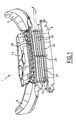
- a body assembly 1 comprising a bodywork part 2, for example made of plastics material.
- the body part 2 is a plastron reinforcement 4 intended to extend under the front of the hood of the motor vehicle (not shown) between the optical projectors 6 of the vehicle.
- the plastron reinforcement 4 is for example fixed in abutment on a transverse beam 8 of the front block of a motor vehicle or fixed to fixing means provided on the projectors 6 or fixed on a structural part located in the optical projectors 6.
- the body assembly further comprises a bumper skin 10 intended to extend on the front face of the body, covering at least part of the plastron reinforcement 4.
- the bumper skin 10 includes an opening 12 extending substantially in the center of the bumper skin 10 and allowing the passage of air from the outside of the motor vehicle to the bodies arranged under the hood of the vehicle when the bumper skin 10 is mounted on the front face of the motor vehicle body.
- the opening 12 extends substantially vertically under the plastron reinforcement 4.
- the opening 2 is delimited by an edge 14 made of material with the bumper skin 1 and extending substantially longitudinally towards the inside of the bumper skin, that is to say toward the arranged members under the hood of the vehicle when the bumper skin 10 is mounted on the vehicle.
- a structural frame 16 is made in one piece with the plastron reinforcement 4 and is integral with a lower end portion 18 of the plastron reinforcement 4 so that the structural frame 16 extends substantially opposite the opening 12 of the bumper skin 10, behind said opening 12.
- the structural frame 16 is for example substantially rectangular and comprises two lateral edges 18 extending between an upper edge 20 and a lower edge 22.
- the edges 18, 20 and 22 define an opening 24 of substantially the same size as the opening 12 of the bumper skin 10.
- at least one edge 18, 20 or 22 of the structural frame 16 is fixed to the edge 14 of the opening 12 of the bumper skin 10 during assembly of said skin 10.
- a rotating flap system is mounted in the opening 24 of the frame 12 and attached to the side edges 18 thereof.
- This system comprises a first plurality of flaps 26 mounted by one end of the flaps 26 on one side of a branch 28 and a second plurality of flaps 30 mounted by one end of the flaps 30 on the other side of the flap. the branch 28.
- the branch 28 extends substantially in the center of the opening 24 between the lower edge 22 and the upper edge 20 of the frame 16, as shown in FIG. Fig. 1 .
- flaps 26 and 30 are mounted on a respective lateral edge 18 of the opening 24 of the frame 16.
- flaps 26 and 30 extending substantially transversely across the entire opening 24 are obtained.
- flaps 26 and 30 are distributed over the height of the opening 24.
- the first and second plurality of flaps each comprise four flaps distributed in height on the branch 28.
- the number flaps can be different, lower or greater than four.
- the flap system does not comprise a branch 28 and only one plurality of flaps extends across the entire opening 24 between the side edges 18.
- the flap system comprises a branch 28 and a single plurality of flaps extending across the entire opening.
- the flaps 26 and 30 are movable in rotation about respective axes A substantially transverse to the edges 18 of the opening 24 and to the branch 28.
- the flaps are thus movable between an open position, shown in the figures, wherein the flaps extend substantially horizontally to allow the passage of air through the opening 24, and a closing position (not shown), wherein the flaps extend substantially vertically so as to close the opening 24 and to prevent the passage of air.
- the control of the rotation of the shutters 26 and 30 is done by an actuator (not shown) fixed on the internal face of the plastron reinforcement 4 and connected via at least one connector (not shown) to the vehicle electrical system. automobile.
- the opening or closing of the flaps 26 and 30 is done according to the cooling needs of the organs arranged under the hood of the motor vehicle. Temperature sensors of these members are for example provided and connected to the electronics of the motor vehicle. Depending on the signals emitted by these sensors, the electrical system is arranged to control the rotation of the shutters 26 and 30 as required.
- the body assembly described above does not require the management of an additional structural frame to report on the bumper skin, the frame 16 being managed in one piece with the plastron reinforcement 4. This allows to to simplify the assembly of the motor vehicle and the management of the stocks of parts.
- the grid generally provided across the opening is not necessary since the shutters fulfill the role of this grid.
- the number of parts and therefore the manufacturing costs are reduced.
- the number of parts being reduced we also obtain a saving of mass of the motor vehicle.
- a particular aesthetic effect can be obtained by controlling the flaps, the appearance of the vehicle being different depending on whether the flaps are in their open position or in their closed position.
Landscapes
- Engineering & Computer Science (AREA)
- Chemical & Material Sciences (AREA)
- Combustion & Propulsion (AREA)
- Transportation (AREA)
- Mechanical Engineering (AREA)
- Superstructure Of Vehicle (AREA)
- Body Structure For Vehicles (AREA)
- Cooling, Air Intake And Gas Exhaust, And Fuel Tank Arrangements In Propulsion Units (AREA)
- Lock And Its Accessories (AREA)
Abstract
Description
- La présente invention concerne un ensemble de carrosserie de véhicule automobile, du type comprenant au moins une pièce de carrosserie destinée à s'étendre sur la face avant d'une caisse de véhicule automobile.
- L'invention concerne également un véhicule automobile comprenant un tel ensemble.
- La peau de pare-choc d'un véhicule automobile comprend généralement une ouverture centrale munie d'une grille permettant le passage de l'air de l'extérieur du véhicule automobile vers les organes du véhicule présents sous le capot afin de permettre un refroidissement de ces organes.
- Afin de moduler ce refroidissement en fonction des besoins des organes, il est connu de prévoir des volets pilotés, montés en rotation, permettant de laisser l'air passer ou d'obturer l'ouverture afin de limiter le flux d'air pénétrant par la peau de pare-choc.
- Les volets pilotés sont montés en rotation sur un cadre structurel disposé derrière l'ouverture et fixé sur la face interne de la peau de pare-choc ou sur la caisse du véhicule automobile. Le document
FR-2 821 817 - Cependant, un tel cadre structurel est une pièce rapportée qu'il convient de monter sur la peau de pare-choc ou sur la caisse du véhicule automobile au moment du montage dudit véhicule. La gestion de cette pièce rapportée (emballage, stockage, transport, montage sur la ligne de montage du véhicule automobile) entraîne une augmentation des coûts et du temps de montage du véhicule automobile et complexifie la ligne de montage.
- L'un des buts de l'invention est de pallier ces inconvénients en proposant un ensemble de carrosserie munie de volets pilotés de structure simplifiée.
- A cet effet, l'invention concerne un ensemble de carrosserie du type précité, dans lequel ladite pièce de carrosserie comprend un cadre structurel réalisé d'un seul tenant avec ladite pièce, ledit cadre structurel étant destiné à s'étendre en regard d'une ouverture d'entrée d'air du véhicule automobile, une pluralité de volets étant fixée aux bords dudit cadre et s'étendant en travers dudit cadre et étant montés en rotation autour d'axes respectifs sensiblement transversaux entre une position d'ouverture où l'air peut traverser le cadre et une position de fermeture dans laquelle les volets obturent le cadre.
- Le cadre structurel étant réalisé d'un seul tenant avec une pièce de carrosserie nécessaire à la réalisation de la face avant du véhicule automobile, il n'est pas nécessaire de prévoir une pièce supplémentaire à fixer sur la peau de pare-choc, ce qui permet de simplifier la ligne de montage et évite la gestion d'une pièce rapportée supplémentaire.
- Selon d'autres caractéristiques de l'ensemble de carrosserie :
- une branche s'étend sensiblement au centre du cadre sensiblement perpendiculairement aux volets, une première pluralité de volets étant fixée à un bord du cadre et à un côté de ladite branche et une deuxième pluralité de volets étant fixée à un autre bord du cadre et à l'autre côté de ladite branche, lesdits volets étant montés en rotation autour d'axes respectifs sensiblement transversaux ;
- la pièce de carrosserie est un renfort de plastron destiné à s'étendre sous l'avant du capot du véhicule automobile ;
- l'ensemble de carrosserie comprend au moins un actionneur fixé à ladite pièce de carrosserie, ledit actionneur étant agencé pour entraîner la rotation des volets ;
- un connecteur électrique est relié audit actionneur ;
- l'actionneur est fixé sur la face interne de la pièce de carrosserie ; et
- l'ensemble de carrosserie comprend en outre une peau de pare-choc, ladite peau s'étendant au moins en partie au-dessus de la pièce de carrosserie.
- L'invention concerne également un véhicule automobile comprenant une caisse, un ensemble de carrosserie étant fixé sur la face avant de ladite caisse, dans lequel l'ensemble de carrosserie est tel que décrit ci-dessus.
- Selon d'autres caractéristiques du véhicule automobile :
- l'actionneur est connecté au système électrique dudit véhicule automobile ; et
- la rotation des volets est commandée par le système électrique du véhicule automobile en fonction des besoins de refroidissement des organes du véhicule automobile présents sous le capot dudit véhicule.
- D'autres aspects et avantages de l'invention apparaîtront à la lecture de la description qui suit, donnée à titre d'exemple et faite en référence aux dessins annexés, dans lesquels :
- la
Fig. 1 est une représentation schématique en perspective d'un ensemble de carrosserie selon l'invention dans son environnement, - la
Fig. 2 est une représentation schématique en coupe de l'ensemble de carrosserie selon l'invention. - Dans la description, les termes « longitudinal » et « transversal » sont définis par rapport aux directions usuelles d'un véhicule automobile monté, c'est-à-dire que la direction longitudinale est définie selon la longueur du véhicule et la direction transversale selon la largeur du véhicule.
- En référence à la
Fig. 1 , on décrit un ensemble de carrosserie 1, comprenant une pièce de carrosserie 2, par exemple réalisée en matière plastique. La pièce de carrosserie 2 est un renfort de plastron 4 destiné à s'étendre sous l'avant du capot du véhicule automobile (non représenté) entre les projecteurs optiques 6 du véhicule. Le renfort de plastron 4 est par exemple fixé en appui sur une poutre transversale 8 du bloc avant d'un véhicule automobile ou fixé à des moyens de fixation prévus sur les projecteurs 6 ou fixé sur une pièce structurelle située en les projecteurs optiques 6. - Comme représenté sur la
Fig. 2 , l'ensemble de carrosserie comprend en outre une peau de pare-choc 10 destinée à s'étendre sur la face avant de la caisse, en recouvrant au moins en partie le renfort de plastron 4. - La peau de pare-choc 10 comprend une ouverture 12 s'étendant sensiblement au centre de la peau de pare-choc 10 et permettant le passage de l'air de l'extérieur du véhicule automobile vers les organes disposés sous le capot du véhicule lorsque la peau de pare-choc 10 est montée sur la face avant de la caisse de véhicule automobile. L'ouverture 12 s'étend sensiblement verticalement sous le renfort de plastron 4.
- L'ouverture 2 est délimitée par un bord 14 venu de matière avec la peau de pare-choc 1 et s'étendant sensiblement longitudinalement vers l'intérieur de la peau de pare-choc, c'est-à-dire vers les organes disposés sous le capot du véhicule lorsque la peau de pare-choc 10 est montée sur le véhicule.
- Un cadre structurel 16 est réalisé d'un seul tenant avec le renfort de plastron 4 et est solidaire d'une partie extrême 18 inférieure du renfort de plastron 4 de sorte que le cadre structurel 16 s'étend sensiblement en regard de l'ouverture 12 de la peau de pare-choc 10, derrière ladite ouverture 12. Le cadre structurel 16 est par exemple sensiblement rectangulaire et comprend deux bords latéraux 18 s'étendant entre un bord supérieur 20 et un bord inférieur 22. Les bords 18, 20 et 22 délimitent une ouverture 24 sensiblement de même dimension que l'ouverture 12 de la peau de pare-choc 10. Selon un mode de réalisation, au moins un bord 18, 20 ou 22 du cadre structurel 16 est fixé au bord 14 de l'ouverture 12 de la peau de pare-choc 10 lors du montage de ladite peau 10.
- Un système de volets pilotés en rotation est monté dans l'ouverture 24 du cadre 12 et fixé aux bords latéraux 18 de celle-ci. Ce système comprend une première pluralité de volets 26 montée par l'une des extrémité des volets 26 sur un côté d'une branche 28 et une deuxième pluralité de volets 30 montée par l'une des extrémités des volets 30 de l'autre côté de la branche 28. La branche 28 s'étend sensiblement au centre de l'ouverture 24 entre le bord inférieur 22 et le bord supérieur 20 du cadre 16, comme représenté sur la
Fig. 1 . - L'autre extrémité des volets 26 et 30 est montée sur un bord latéral 18 respectif de l'ouverture 24 du cadre 16. Ainsi, on obtient des volets 26 et 30 s'étendant sensiblement transversalement en travers de toute l'ouverture 24. Les volets 26 et 30 sont répartis sur la hauteur de l'ouverture 24. Selon le mode de réalisation représenté sur les figures, la première et la deuxième pluralité de volets comprennent chacune quatre volets répartis en hauteur sur la branche 28. En variante, le nombre de volets peut être différent, inférieur ou supérieur à quatre.
- En variante, le système de volets ne comprend pas de branche 28 et une seule pluralité de volets s'étend en travers de toute l'ouverture 24 entre les bords latéraux 18. Selon une autre variante, le système de volets comprend une branche 28 et une seule pluralité de volets s'étendant en travers de toute l'ouverture.
- Les volets 26 et 30 sont mobiles en rotation autour d'axes A respectifs sensiblement transversaux par rapport aux bords 18 de l'ouverture 24 et à la branche 28. Les volets sont ainsi mobile entre une position d'ouverture, représentée sur les figures, dans laquelle les volets s'étendent sensiblement horizontalement afin de permettre le passage de l'air par l'ouverture 24, et une position de fermeture (non représentée), dans laquelle les volets s'étendent sensiblement verticalement de sorte à obturer l'ouverture 24 et à empêcher le passage de l'air.
- Le pilotage de la rotation des volets 26 et 30 se fait par un actionneur (non représenté) fixé sur la face interne du renfort de plastron 4 et relié par l'intermédiaire d'au moins un connecteur (non représenté) au système électrique du véhicule automobile.
- L'ouverture ou la fermeture des volets 26 et 30 se fait selon les besoins en refroidissement des organes disposés sous le capot du véhicule automobile. Des capteurs de température de ces organes sont par exemple prévus et reliés à l'électronique du véhicule automobile. En fonction des signaux émis par ces capteurs, le système électrique est agencé pour piloter la rotation des volets 26 et 30 selon les besoins.
- L'ensemble de carrosserie décrit ci-dessus ne nécessite pas la gestion d'un cadre structurel supplémentaire à rapporter sur la peau de pare-choc, le cadre 16 étant géré d'une seule pièce avec le renfort de plastron 4. Ceci permet de simplifier le montage du véhicule automobile et la gestion des stocks de pièces.
- En outre, la grille généralement prévue en travers de l'ouverture n'est pas nécessaire puisque les volets remplissent le rôle de cette grille. Ainsi, le nombre de pièces et donc les coûts de fabrication sont réduits. Le nombre de pièces étant réduit, on obtient également un gain de masse du véhicule automobile.
- Un effet esthétique particulier peut être obtenu par le pilotage des volets, l'aspect du véhicule étant différent selon que les volets sont dans leur position ouverte ou dans leur position fermée.
Claims (10)
- Ensemble de carrosserie (1) de véhicule automobile, comprenant au moins une pièce de carrosserie (2) destinée à s'étendre sur la face avant d'une caisse de véhicule automobile, caractérisé en ce que ladite pièce de carrosserie (2) comprend un cadre structurel (16) réalisé d'un seul tenant avec ladite pièce (2), ledit cadre structurel (16) étant destiné à s'étendre en regard d'une ouverture d'entrée d'air (12) du véhicule automobile, une pluralité de volets (26, 30) étant fixée aux bords (18) dudit cadre (16) et s'étendant en travers dudit cadre (16) et étant montés en rotation autour d'axes (A) respectifs sensiblement transversaux entre une position d'ouverture où l'air peut traverser le cadre (16) et une position de fermeture dans laquelle les volets (26, 30) obturent le cadre (16).
- Ensemble de carrosserie selon la revendication 1, caractérisé en ce qu'une branche (28) s'étend sensiblement au centre du cadre (16) sensiblement perpendiculairement aux volets (26, 30), une première pluralité de volets (26) étant fixée à un bord (18) du cadre (16) et à un côté de ladite branche (28) et une deuxième pluralité de volets (30) étant fixée à un autre bord (18) du cadre (16) et à l'autre côté de ladite branche (28), lesdits volets (26, 30) étant montés en rotation autour d'axes (A) respectifs sensiblement transversaux.
- Ensemble de carrosserie selon la revendication 1 ou 2, caractérisé en ce que la pièce de carrosserie (2) est un renfort de plastron (4), destiné à s'étendre sous l'avant du capot du véhicule automobile.
- Ensemble de carrosserie selon l'une quelconque des revendications 1 à 3, caractérisé en ce qu'il comprend au moins un actionneur fixé à ladite pièce de carrosserie (2), ledit actionneur étant agencé pour entraîner la rotation des volets (26, 30).
- Ensemble de carrosserie selon la revendication 4, caractérisé en ce qu'un connecteur électrique est relié audit actionneur.
- Ensemble de carrosserie selon la revendication 4 ou 5, caractérisé en ce que l'actionneur est fixé sur la face interne de la pièce de carrosserie (2).
- Ensemble de carrosserie selon l'une quelconque des revendications 1 à 6, caractérisé en ce qu'il comprend en outre une peau de pare-choc (10), ladite peau (10) s'étendant au moins en partie au-dessus de la pièce de carrosserie (2), ladite peau (10) comprenant au moins une ouverture d'entrée d'air (12), ladite ouverture (12) s'étendant en regard du cadre structurel (16).
- Véhicule automobile comprenant une caisse, un ensemble de carrosserie (1) étant fixé sur la face avant de ladite caisse, caractérisé en ce que l'ensemble de carrosserie (1) est selon l'une quelconque des revendications 1 à 7.
- Véhicule automobile selon la revendication 8, lorsqu'elle dépend de l'une des revendications 4 à 6, caractérisé en ce que l'actionneur est connecté au système électrique dudit véhicule automobile.
- Véhicule automobile selon la revendication 9, caractérisé en ce que la rotation des volets (26, 30) est commandée par le système électrique du véhicule automobile en fonction des besoins de refroidissement des organes du véhicule automobile présents sous le capot dudit véhicule.
Applications Claiming Priority (1)
| Application Number | Priority Date | Filing Date | Title |
|---|---|---|---|
| FR0858263A FR2939373B1 (fr) | 2008-12-04 | 2008-12-04 | Ensemble de carrosserie de vehicule automobile munie de volets montes en rotation |
Publications (2)
| Publication Number | Publication Date |
|---|---|
| EP2193948A1 true EP2193948A1 (fr) | 2010-06-09 |
| EP2193948B1 EP2193948B1 (fr) | 2013-03-27 |
Family
ID=40810703
Family Applications (1)
| Application Number | Title | Priority Date | Filing Date |
|---|---|---|---|
| EP09306123A Not-in-force EP2193948B1 (fr) | 2008-12-04 | 2009-11-23 | Ensemble de carrosserie de véhicule automobile munie de volets montés en rotation |
Country Status (3)
| Country | Link |
|---|---|
| EP (1) | EP2193948B1 (fr) |
| ES (1) | ES2403076T3 (fr) |
| FR (1) | FR2939373B1 (fr) |
Citations (5)
| Publication number | Priority date | Publication date | Assignee | Title |
|---|---|---|---|---|
| GB2082520A (en) * | 1980-08-28 | 1982-03-10 | Talbot Motor | Cooling of vehicle engines |
| DE202004010030U1 (de) * | 2004-06-26 | 2004-09-16 | Hella-Behr Fahrzeugsysteme Gmbh | Frontend für Kraftfahrzeuge, wie Personen- oder Kleinlastkraftwagen |
| EP1522448A1 (fr) * | 2003-10-06 | 2005-04-13 | Peugeot Citroen Automobiles S.A. | Dispositif de régulation d'un flux d'air entrant notamment sous le capot d'un véhicule automobile |
| DE102004026419A1 (de) * | 2004-05-29 | 2005-12-22 | Bayerische Motoren Werke Ag | Vorrichtung zur Abstimmung des Luftdurchsatzes durch im Frontbereich eines Kraftfahrzeuges vorgesehene Eintrittsöffnungen, insbesondere zur Einstellung der Luftzuströmung zu einem Motorraum eines Kraftfahrzeuges |
| EP1637442A1 (fr) * | 2004-09-20 | 2006-03-22 | Faurecia Bloc Avant | Face avant pour véhicule automobile et procédé de montage correspondant |
-
2008
- 2008-12-04 FR FR0858263A patent/FR2939373B1/fr not_active Expired - Fee Related
-
2009
- 2009-11-23 ES ES09306123T patent/ES2403076T3/es active Active
- 2009-11-23 EP EP09306123A patent/EP2193948B1/fr not_active Not-in-force
Patent Citations (5)
| Publication number | Priority date | Publication date | Assignee | Title |
|---|---|---|---|---|
| GB2082520A (en) * | 1980-08-28 | 1982-03-10 | Talbot Motor | Cooling of vehicle engines |
| EP1522448A1 (fr) * | 2003-10-06 | 2005-04-13 | Peugeot Citroen Automobiles S.A. | Dispositif de régulation d'un flux d'air entrant notamment sous le capot d'un véhicule automobile |
| DE102004026419A1 (de) * | 2004-05-29 | 2005-12-22 | Bayerische Motoren Werke Ag | Vorrichtung zur Abstimmung des Luftdurchsatzes durch im Frontbereich eines Kraftfahrzeuges vorgesehene Eintrittsöffnungen, insbesondere zur Einstellung der Luftzuströmung zu einem Motorraum eines Kraftfahrzeuges |
| DE202004010030U1 (de) * | 2004-06-26 | 2004-09-16 | Hella-Behr Fahrzeugsysteme Gmbh | Frontend für Kraftfahrzeuge, wie Personen- oder Kleinlastkraftwagen |
| EP1637442A1 (fr) * | 2004-09-20 | 2006-03-22 | Faurecia Bloc Avant | Face avant pour véhicule automobile et procédé de montage correspondant |
Also Published As
| Publication number | Publication date |
|---|---|
| EP2193948B1 (fr) | 2013-03-27 |
| FR2939373B1 (fr) | 2011-02-11 |
| ES2403076T3 (es) | 2013-05-14 |
| FR2939373A1 (fr) | 2010-06-11 |
Similar Documents
| Publication | Publication Date | Title |
|---|---|---|
| EP3634800B1 (fr) | Dispositif d'obturation d'entree d'air de vehicule automobile et procede de fabrication d'un tel dispositif d'obturation | |
| EP3702189B1 (fr) | Dispositif d'aération pour un véhicule | |
| EP0605325A1 (fr) | Dispositif de régulation d'un flux d'air dans un passage de circulation, en particulier pour un radiateur de refroidissement de véhicule automobile | |
| EP2193948B1 (fr) | Ensemble de carrosserie de véhicule automobile munie de volets montés en rotation | |
| FR2939371A1 (fr) | Peau de pare-chocs de vehicule automobile munie de volets montes en rotation | |
| FR3112103A1 (fr) | véhicule possédant une façade avant dotée d’une pièce de structure multifonction | |
| EP4334152B1 (fr) | Volet extrude pour dispositif d'obturation d'entree d'air de face avant de vehicule automobile | |
| FR3092528A1 (fr) | Dispositif d’obturation pour entrée d’air de face avant de véhicule automobile comportant un dispositif de désolidarisation de volet | |
| FR3032154A1 (fr) | Dispositif de sortie d'air d'un systeme d'aeration pour vehicule | |
| FR2965857A1 (fr) | Dispositif de commande de flux d'air comprenant une partie standard commune pour plusieurs modeles de vehicules automobiles et gamme associee. | |
| FR2976227A1 (fr) | Element de support d'elements fonctionnels pour vehicule automobile. | |
| FR2933042A3 (fr) | Dispositif d'occultation d'une partie de la face frontale d'un module de refroidissement d'un moteur de vehicule | |
| EP1690709B1 (fr) | Aérateur à ailettes pivotantes et à ailettes rotatives pour véhicules, notamment pour automobile | |
| EP4444578B1 (fr) | Dispositif lumineux d'un véhicule automobile | |
| EP4225600B1 (fr) | Dispositif d'obturation de flux d'air de face avant de véhicule automobile comportant plusieurs cadres supports | |
| EP3044020B1 (fr) | Hayon pour véhicule automobile avec ossature de support et véhicule correspondant | |
| EP4444579B1 (fr) | Dispositif fonctionnel d'un véhicule automobile | |
| EP0962346A1 (fr) | Dispositif d'obturation d'une baie ménagée dans la carrosserie d'un véhicule, à coulissement extérieur, et procédé de fabrication et de montage correspondant | |
| FR2889281A1 (fr) | Vanne a clapet et clapet pour une telle vanne | |
| FR2929895A1 (fr) | Agencement d'un siege de vehicule automobile et d'un element de rangement qui forme une seule piece avec le siege | |
| FR2521268A1 (fr) | Volet de dosage pour conduit de ventilation | |
| EP1690708B1 (fr) | Aérateur pour véhicule comprenant des ailettes portées par un corps cylindrique rotatif | |
| EP3519652B1 (fr) | Commande d'ouverture extérieure | |
| EP4707017A1 (fr) | Dispositif d' aération pour un véhicule | |
| FR3145703A1 (fr) | Calandre de véhicule automobile à entrée d’air modulable |
Legal Events
| Date | Code | Title | Description |
|---|---|---|---|
| PUAI | Public reference made under article 153(3) epc to a published international application that has entered the european phase |
Free format text: ORIGINAL CODE: 0009012 |
|
| AK | Designated contracting states |
Kind code of ref document: A1 Designated state(s): AT BE BG CH CY CZ DE DK EE ES FI FR GB GR HR HU IE IS IT LI LT LU LV MC MK MT NL NO PL PT RO SE SI SK SM TR |
|
| AX | Request for extension of the european patent |
Extension state: AL BA RS |
|
| 17P | Request for examination filed |
Effective date: 20101130 |
|
| 17Q | First examination report despatched |
Effective date: 20110125 |
|
| GRAP | Despatch of communication of intention to grant a patent |
Free format text: ORIGINAL CODE: EPIDOSNIGR1 |
|
| GRAS | Grant fee paid |
Free format text: ORIGINAL CODE: EPIDOSNIGR3 |
|
| GRAA | (expected) grant |
Free format text: ORIGINAL CODE: 0009210 |
|
| AK | Designated contracting states |
Kind code of ref document: B1 Designated state(s): AT BE BG CH CY CZ DE DK EE ES FI FR GB GR HR HU IE IS IT LI LT LU LV MC MK MT NL NO PL PT RO SE SI SK SM TR |
|
| REG | Reference to a national code |
Ref country code: GB Ref legal event code: FG4D Free format text: NOT ENGLISH |
|
| REG | Reference to a national code |
Ref country code: CH Ref legal event code: EP |
|
| REG | Reference to a national code |
Ref country code: AT Ref legal event code: REF Ref document number: 603150 Country of ref document: AT Kind code of ref document: T Effective date: 20130415 |
|
| REG | Reference to a national code |
Ref country code: IE Ref legal event code: FG4D Free format text: LANGUAGE OF EP DOCUMENT: FRENCH |
|
| REG | Reference to a national code |
Ref country code: ES Ref legal event code: FG2A Ref document number: 2403076 Country of ref document: ES Kind code of ref document: T3 Effective date: 20130514 |
|
| REG | Reference to a national code |
Ref country code: DE Ref legal event code: R096 Ref document number: 602009014367 Country of ref document: DE Effective date: 20130523 |
|
| PG25 | Lapsed in a contracting state [announced via postgrant information from national office to epo] |
Ref country code: SE Free format text: LAPSE BECAUSE OF FAILURE TO SUBMIT A TRANSLATION OF THE DESCRIPTION OR TO PAY THE FEE WITHIN THE PRESCRIBED TIME-LIMIT Effective date: 20130327 Ref country code: NO Free format text: LAPSE BECAUSE OF FAILURE TO SUBMIT A TRANSLATION OF THE DESCRIPTION OR TO PAY THE FEE WITHIN THE PRESCRIBED TIME-LIMIT Effective date: 20130627 Ref country code: LT Free format text: LAPSE BECAUSE OF FAILURE TO SUBMIT A TRANSLATION OF THE DESCRIPTION OR TO PAY THE FEE WITHIN THE PRESCRIBED TIME-LIMIT Effective date: 20130327 Ref country code: BG Free format text: LAPSE BECAUSE OF FAILURE TO SUBMIT A TRANSLATION OF THE DESCRIPTION OR TO PAY THE FEE WITHIN THE PRESCRIBED TIME-LIMIT Effective date: 20130627 |
|
| REG | Reference to a national code |
Ref country code: AT Ref legal event code: MK05 Ref document number: 603150 Country of ref document: AT Kind code of ref document: T Effective date: 20130327 |
|
| REG | Reference to a national code |
Ref country code: LT Ref legal event code: MG4D |
|
| PG25 | Lapsed in a contracting state [announced via postgrant information from national office to epo] |
Ref country code: SI Free format text: LAPSE BECAUSE OF FAILURE TO SUBMIT A TRANSLATION OF THE DESCRIPTION OR TO PAY THE FEE WITHIN THE PRESCRIBED TIME-LIMIT Effective date: 20130327 Ref country code: GR Free format text: LAPSE BECAUSE OF FAILURE TO SUBMIT A TRANSLATION OF THE DESCRIPTION OR TO PAY THE FEE WITHIN THE PRESCRIBED TIME-LIMIT Effective date: 20130628 Ref country code: FI Free format text: LAPSE BECAUSE OF FAILURE TO SUBMIT A TRANSLATION OF THE DESCRIPTION OR TO PAY THE FEE WITHIN THE PRESCRIBED TIME-LIMIT Effective date: 20130327 Ref country code: LV Free format text: LAPSE BECAUSE OF FAILURE TO SUBMIT A TRANSLATION OF THE DESCRIPTION OR TO PAY THE FEE WITHIN THE PRESCRIBED TIME-LIMIT Effective date: 20130327 |
|
| REG | Reference to a national code |
Ref country code: NL Ref legal event code: VDEP Effective date: 20130327 |
|
| PG25 | Lapsed in a contracting state [announced via postgrant information from national office to epo] |
Ref country code: HR Free format text: LAPSE BECAUSE OF FAILURE TO SUBMIT A TRANSLATION OF THE DESCRIPTION OR TO PAY THE FEE WITHIN THE PRESCRIBED TIME-LIMIT Effective date: 20130327 |
|
| PG25 | Lapsed in a contracting state [announced via postgrant information from national office to epo] |
Ref country code: NL Free format text: LAPSE BECAUSE OF FAILURE TO SUBMIT A TRANSLATION OF THE DESCRIPTION OR TO PAY THE FEE WITHIN THE PRESCRIBED TIME-LIMIT Effective date: 20130327 Ref country code: AT Free format text: LAPSE BECAUSE OF FAILURE TO SUBMIT A TRANSLATION OF THE DESCRIPTION OR TO PAY THE FEE WITHIN THE PRESCRIBED TIME-LIMIT Effective date: 20130327 Ref country code: RO Free format text: LAPSE BECAUSE OF FAILURE TO SUBMIT A TRANSLATION OF THE DESCRIPTION OR TO PAY THE FEE WITHIN THE PRESCRIBED TIME-LIMIT Effective date: 20130327 Ref country code: EE Free format text: LAPSE BECAUSE OF FAILURE TO SUBMIT A TRANSLATION OF THE DESCRIPTION OR TO PAY THE FEE WITHIN THE PRESCRIBED TIME-LIMIT Effective date: 20130327 Ref country code: SK Free format text: LAPSE BECAUSE OF FAILURE TO SUBMIT A TRANSLATION OF THE DESCRIPTION OR TO PAY THE FEE WITHIN THE PRESCRIBED TIME-LIMIT Effective date: 20130327 Ref country code: PT Free format text: LAPSE BECAUSE OF FAILURE TO SUBMIT A TRANSLATION OF THE DESCRIPTION OR TO PAY THE FEE WITHIN THE PRESCRIBED TIME-LIMIT Effective date: 20130729 Ref country code: IS Free format text: LAPSE BECAUSE OF FAILURE TO SUBMIT A TRANSLATION OF THE DESCRIPTION OR TO PAY THE FEE WITHIN THE PRESCRIBED TIME-LIMIT Effective date: 20130727 Ref country code: CZ Free format text: LAPSE BECAUSE OF FAILURE TO SUBMIT A TRANSLATION OF THE DESCRIPTION OR TO PAY THE FEE WITHIN THE PRESCRIBED TIME-LIMIT Effective date: 20130327 |
|
| PG25 | Lapsed in a contracting state [announced via postgrant information from national office to epo] |
Ref country code: CY Free format text: LAPSE BECAUSE OF FAILURE TO SUBMIT A TRANSLATION OF THE DESCRIPTION OR TO PAY THE FEE WITHIN THE PRESCRIBED TIME-LIMIT Effective date: 20130327 Ref country code: PL Free format text: LAPSE BECAUSE OF FAILURE TO SUBMIT A TRANSLATION OF THE DESCRIPTION OR TO PAY THE FEE WITHIN THE PRESCRIBED TIME-LIMIT Effective date: 20130327 |
|
| PG25 | Lapsed in a contracting state [announced via postgrant information from national office to epo] |
Ref country code: DK Free format text: LAPSE BECAUSE OF FAILURE TO SUBMIT A TRANSLATION OF THE DESCRIPTION OR TO PAY THE FEE WITHIN THE PRESCRIBED TIME-LIMIT Effective date: 20130327 |
|
| PLBE | No opposition filed within time limit |
Free format text: ORIGINAL CODE: 0009261 |
|
| STAA | Information on the status of an ep patent application or granted ep patent |
Free format text: STATUS: NO OPPOSITION FILED WITHIN TIME LIMIT |
|
| PG25 | Lapsed in a contracting state [announced via postgrant information from national office to epo] |
Ref country code: IT Free format text: LAPSE BECAUSE OF FAILURE TO SUBMIT A TRANSLATION OF THE DESCRIPTION OR TO PAY THE FEE WITHIN THE PRESCRIBED TIME-LIMIT Effective date: 20130327 |
|
| 26N | No opposition filed |
Effective date: 20140103 |
|
| REG | Reference to a national code |
Ref country code: DE Ref legal event code: R097 Ref document number: 602009014367 Country of ref document: DE Effective date: 20140103 |
|
| BERE | Be: lapsed |
Owner name: FAURECIA BLOC AVANT Effective date: 20131130 |
|
| REG | Reference to a national code |
Ref country code: CH Ref legal event code: PL |
|
| GBPC | Gb: european patent ceased through non-payment of renewal fee |
Effective date: 20131123 |
|
| PG25 | Lapsed in a contracting state [announced via postgrant information from national office to epo] |
Ref country code: MC Free format text: LAPSE BECAUSE OF FAILURE TO SUBMIT A TRANSLATION OF THE DESCRIPTION OR TO PAY THE FEE WITHIN THE PRESCRIBED TIME-LIMIT Effective date: 20130327 Ref country code: LI Free format text: LAPSE BECAUSE OF NON-PAYMENT OF DUE FEES Effective date: 20131130 Ref country code: CH Free format text: LAPSE BECAUSE OF NON-PAYMENT OF DUE FEES Effective date: 20131130 |
|
| REG | Reference to a national code |
Ref country code: IE Ref legal event code: MM4A |
|
| PG25 | Lapsed in a contracting state [announced via postgrant information from national office to epo] |
Ref country code: BE Free format text: LAPSE BECAUSE OF NON-PAYMENT OF DUE FEES Effective date: 20131130 |
|
| PG25 | Lapsed in a contracting state [announced via postgrant information from national office to epo] |
Ref country code: IE Free format text: LAPSE BECAUSE OF NON-PAYMENT OF DUE FEES Effective date: 20131123 |
|
| PG25 | Lapsed in a contracting state [announced via postgrant information from national office to epo] |
Ref country code: GB Free format text: LAPSE BECAUSE OF NON-PAYMENT OF DUE FEES Effective date: 20131123 |
|
| PG25 | Lapsed in a contracting state [announced via postgrant information from national office to epo] |
Ref country code: SM Free format text: LAPSE BECAUSE OF FAILURE TO SUBMIT A TRANSLATION OF THE DESCRIPTION OR TO PAY THE FEE WITHIN THE PRESCRIBED TIME-LIMIT Effective date: 20130327 |
|
| PG25 | Lapsed in a contracting state [announced via postgrant information from national office to epo] |
Ref country code: TR Free format text: LAPSE BECAUSE OF FAILURE TO SUBMIT A TRANSLATION OF THE DESCRIPTION OR TO PAY THE FEE WITHIN THE PRESCRIBED TIME-LIMIT Effective date: 20130327 |
|
| PG25 | Lapsed in a contracting state [announced via postgrant information from national office to epo] |
Ref country code: LU Free format text: LAPSE BECAUSE OF NON-PAYMENT OF DUE FEES Effective date: 20131123 Ref country code: HU Free format text: LAPSE BECAUSE OF FAILURE TO SUBMIT A TRANSLATION OF THE DESCRIPTION OR TO PAY THE FEE WITHIN THE PRESCRIBED TIME-LIMIT; INVALID AB INITIO Effective date: 20091123 Ref country code: MK Free format text: LAPSE BECAUSE OF FAILURE TO SUBMIT A TRANSLATION OF THE DESCRIPTION OR TO PAY THE FEE WITHIN THE PRESCRIBED TIME-LIMIT Effective date: 20130327 |
|
| PG25 | Lapsed in a contracting state [announced via postgrant information from national office to epo] |
Ref country code: MT Free format text: LAPSE BECAUSE OF FAILURE TO SUBMIT A TRANSLATION OF THE DESCRIPTION OR TO PAY THE FEE WITHIN THE PRESCRIBED TIME-LIMIT Effective date: 20130327 |
|
| REG | Reference to a national code |
Ref country code: FR Ref legal event code: PLFP Year of fee payment: 7 |
|
| REG | Reference to a national code |
Ref country code: DE Ref legal event code: R082 Ref document number: 602009014367 Country of ref document: DE |
|
| REG | Reference to a national code |
Ref country code: FR Ref legal event code: PLFP Year of fee payment: 8 |
|
| REG | Reference to a national code |
Ref country code: FR Ref legal event code: PLFP Year of fee payment: 9 |
|
| PGFP | Annual fee paid to national office [announced via postgrant information from national office to epo] |
Ref country code: DE Payment date: 20171019 Year of fee payment: 9 Ref country code: FR Payment date: 20171020 Year of fee payment: 9 |
|
| PGFP | Annual fee paid to national office [announced via postgrant information from national office to epo] |
Ref country code: ES Payment date: 20171204 Year of fee payment: 9 |
|
| REG | Reference to a national code |
Ref country code: DE Ref legal event code: R119 Ref document number: 602009014367 Country of ref document: DE |
|
| PG25 | Lapsed in a contracting state [announced via postgrant information from national office to epo] |
Ref country code: FR Free format text: LAPSE BECAUSE OF NON-PAYMENT OF DUE FEES Effective date: 20181130 Ref country code: DE Free format text: LAPSE BECAUSE OF NON-PAYMENT OF DUE FEES Effective date: 20190601 |
|
| REG | Reference to a national code |
Ref country code: ES Ref legal event code: FD2A Effective date: 20200108 |
|
| PG25 | Lapsed in a contracting state [announced via postgrant information from national office to epo] |
Ref country code: ES Free format text: LAPSE BECAUSE OF NON-PAYMENT OF DUE FEES Effective date: 20181124 |