EP2193867A1 - Electrode en fil d'acier destinée à la coupe par étincelage - Google Patents
Electrode en fil d'acier destinée à la coupe par étincelage Download PDFInfo
- Publication number
- EP2193867A1 EP2193867A1 EP08170563A EP08170563A EP2193867A1 EP 2193867 A1 EP2193867 A1 EP 2193867A1 EP 08170563 A EP08170563 A EP 08170563A EP 08170563 A EP08170563 A EP 08170563A EP 2193867 A1 EP2193867 A1 EP 2193867A1
- Authority
- EP
- European Patent Office
- Prior art keywords
- brass
- wire electrode
- cladding layer
- sheath
- core
- Prior art date
- Legal status (The legal status is an assumption and is not a legal conclusion. Google has not performed a legal analysis and makes no representation as to the accuracy of the status listed.)
- Granted
Links
- 238000005520 cutting process Methods 0.000 title claims description 18
- 229910001369 Brass Inorganic materials 0.000 claims abstract description 125
- 239000010951 brass Substances 0.000 claims abstract description 125
- 238000000034 method Methods 0.000 claims abstract description 19
- 229910000730 Beta brass Inorganic materials 0.000 claims abstract description 8
- 239000002184 metal Substances 0.000 claims abstract description 8
- 229910052751 metal Inorganic materials 0.000 claims abstract description 8
- 229910001092 metal group alloy Inorganic materials 0.000 claims abstract description 7
- 238000005253 cladding Methods 0.000 claims description 94
- 239000011701 zinc Substances 0.000 claims description 34
- HCHKCACWOHOZIP-UHFFFAOYSA-N Zinc Chemical compound [Zn] HCHKCACWOHOZIP-UHFFFAOYSA-N 0.000 claims description 31
- 229910052725 zinc Inorganic materials 0.000 claims description 31
- RYGMFSIKBFXOCR-UHFFFAOYSA-N Copper Chemical compound [Cu] RYGMFSIKBFXOCR-UHFFFAOYSA-N 0.000 claims description 16
- 239000010949 copper Substances 0.000 claims description 16
- 229910052802 copper Inorganic materials 0.000 claims description 15
- 238000009792 diffusion process Methods 0.000 claims description 14
- 238000000137 annealing Methods 0.000 claims description 13
- 239000000203 mixture Substances 0.000 claims description 13
- XLOMVQKBTHCTTD-UHFFFAOYSA-N Zinc monoxide Chemical compound [Zn]=O XLOMVQKBTHCTTD-UHFFFAOYSA-N 0.000 claims description 8
- 229910001015 Alpha brass Inorganic materials 0.000 claims description 7
- 229910001297 Zn alloy Inorganic materials 0.000 claims description 7
- 238000009760 electrical discharge machining Methods 0.000 claims description 7
- 238000001816 cooling Methods 0.000 claims description 5
- TVZPLCNGKSPOJA-UHFFFAOYSA-N copper zinc Chemical compound [Cu].[Zn] TVZPLCNGKSPOJA-UHFFFAOYSA-N 0.000 claims description 4
- 238000010438 heat treatment Methods 0.000 claims description 4
- 239000011787 zinc oxide Substances 0.000 claims description 4
- 239000013078 crystal Substances 0.000 claims description 3
- 239000002244 precipitate Substances 0.000 claims description 2
- 238000000576 coating method Methods 0.000 abstract description 12
- 238000004519 manufacturing process Methods 0.000 abstract description 11
- 239000011248 coating agent Substances 0.000 abstract description 8
- 239000011162 core material Substances 0.000 description 51
- 230000007704 transition Effects 0.000 description 17
- 230000003628 erosive effect Effects 0.000 description 16
- 229910002535 CuZn Inorganic materials 0.000 description 4
- 239000000463 material Substances 0.000 description 4
- 230000000694 effects Effects 0.000 description 3
- 230000002829 reductive effect Effects 0.000 description 3
- 229910000831 Steel Inorganic materials 0.000 description 2
- 229910045601 alloy Inorganic materials 0.000 description 2
- 239000000956 alloy Substances 0.000 description 2
- 230000015572 biosynthetic process Effects 0.000 description 2
- 238000010622 cold drawing Methods 0.000 description 2
- 230000007423 decrease Effects 0.000 description 2
- 238000013461 design Methods 0.000 description 2
- 150000002500 ions Chemical class 0.000 description 2
- 230000001788 irregular Effects 0.000 description 2
- 150000002739 metals Chemical class 0.000 description 2
- 238000012545 processing Methods 0.000 description 2
- 238000004513 sizing Methods 0.000 description 2
- 239000010959 steel Substances 0.000 description 2
- 241001290864 Schoenoplectus Species 0.000 description 1
- 230000002411 adverse Effects 0.000 description 1
- 239000000919 ceramic Substances 0.000 description 1
- 238000006243 chemical reaction Methods 0.000 description 1
- 239000002131 composite material Substances 0.000 description 1
- 239000008367 deionised water Substances 0.000 description 1
- 229910021641 deionized water Inorganic materials 0.000 description 1
- 230000001419 dependent effect Effects 0.000 description 1
- 238000011161 development Methods 0.000 description 1
- 230000018109 developmental process Effects 0.000 description 1
- 238000007598 dipping method Methods 0.000 description 1
- 238000009713 electroplating Methods 0.000 description 1
- 238000005530 etching Methods 0.000 description 1
- 238000011156 evaluation Methods 0.000 description 1
- 239000012530 fluid Substances 0.000 description 1
- 238000000227 grinding Methods 0.000 description 1
- 238000010884 ion-beam technique Methods 0.000 description 1
- 238000003754 machining Methods 0.000 description 1
- 239000011159 matrix material Substances 0.000 description 1
- 230000036961 partial effect Effects 0.000 description 1
- 239000002245 particle Substances 0.000 description 1
- 238000005498 polishing Methods 0.000 description 1
- 238000002360 preparation method Methods 0.000 description 1
- 238000004886 process control Methods 0.000 description 1
- 230000001681 protective effect Effects 0.000 description 1
- 230000005855 radiation Effects 0.000 description 1
- 238000001878 scanning electron micrograph Methods 0.000 description 1
- 229910052709 silver Inorganic materials 0.000 description 1
- 239000004332 silver Substances 0.000 description 1
- 238000004901 spalling Methods 0.000 description 1
- 239000007858 starting material Substances 0.000 description 1
- 238000005482 strain hardening Methods 0.000 description 1
- 239000000758 substrate Substances 0.000 description 1
- 238000012546 transfer Methods 0.000 description 1
- XLYOFNOQVPJJNP-UHFFFAOYSA-N water Chemical compound O XLYOFNOQVPJJNP-UHFFFAOYSA-N 0.000 description 1
- 238000005491 wire drawing Methods 0.000 description 1
Images
Classifications
-
- B—PERFORMING OPERATIONS; TRANSPORTING
- B23—MACHINE TOOLS; METAL-WORKING NOT OTHERWISE PROVIDED FOR
- B23H—WORKING OF METAL BY THE ACTION OF A HIGH CONCENTRATION OF ELECTRIC CURRENT ON A WORKPIECE USING AN ELECTRODE WHICH TAKES THE PLACE OF A TOOL; SUCH WORKING COMBINED WITH OTHER FORMS OF WORKING OF METAL
- B23H7/00—Processes or apparatus applicable to both electrical discharge machining and electrochemical machining
- B23H7/02—Wire-cutting
- B23H7/08—Wire electrodes
-
- B—PERFORMING OPERATIONS; TRANSPORTING
- B23—MACHINE TOOLS; METAL-WORKING NOT OTHERWISE PROVIDED FOR
- B23H—WORKING OF METAL BY THE ACTION OF A HIGH CONCENTRATION OF ELECTRIC CURRENT ON A WORKPIECE USING AN ELECTRODE WHICH TAKES THE PLACE OF A TOOL; SUCH WORKING COMBINED WITH OTHER FORMS OF WORKING OF METAL
- B23H7/00—Processes or apparatus applicable to both electrical discharge machining and electrochemical machining
- B23H7/02—Wire-cutting
- B23H7/08—Wire electrodes
- B23H7/10—Supporting, winding or electrical connection of wire-electrode
-
- Y—GENERAL TAGGING OF NEW TECHNOLOGICAL DEVELOPMENTS; GENERAL TAGGING OF CROSS-SECTIONAL TECHNOLOGIES SPANNING OVER SEVERAL SECTIONS OF THE IPC; TECHNICAL SUBJECTS COVERED BY FORMER USPC CROSS-REFERENCE ART COLLECTIONS [XRACs] AND DIGESTS
- Y10—TECHNICAL SUBJECTS COVERED BY FORMER USPC
- Y10T—TECHNICAL SUBJECTS COVERED BY FORMER US CLASSIFICATION
- Y10T29/00—Metal working
- Y10T29/49—Method of mechanical manufacture
- Y10T29/49002—Electrical device making
- Y10T29/49117—Conductor or circuit manufacturing
-
- Y—GENERAL TAGGING OF NEW TECHNOLOGICAL DEVELOPMENTS; GENERAL TAGGING OF CROSS-SECTIONAL TECHNOLOGIES SPANNING OVER SEVERAL SECTIONS OF THE IPC; TECHNICAL SUBJECTS COVERED BY FORMER USPC CROSS-REFERENCE ART COLLECTIONS [XRACs] AND DIGESTS
- Y10—TECHNICAL SUBJECTS COVERED BY FORMER USPC
- Y10T—TECHNICAL SUBJECTS COVERED BY FORMER US CLASSIFICATION
- Y10T428/00—Stock material or miscellaneous articles
- Y10T428/12—All metal or with adjacent metals
- Y10T428/12493—Composite; i.e., plural, adjacent, spatially distinct metal components [e.g., layers, joint, etc.]
- Y10T428/12771—Transition metal-base component
- Y10T428/12861—Group VIII or IB metal-base component
- Y10T428/12903—Cu-base component
Definitions
- the present invention relates to an EDM wire electrode having a core comprising a metal or a metal alloy and a cladding surrounding the core comprising one or more cladding layers, at least one of which comprises a mixed phase of ⁇ - and / or ⁇ '- Brass and ⁇ -brass, and a method for producing such a wire electrode.
- EDM Electrical discharge machining
- spark erosion cutting or wire eroding One particular spark erosion process in which the tool is formed by a taut, thin wire having typical diameters in a range of about 0.02 to 0.4 mm is spark erosion cutting or wire eroding. As the wire wears through material removal during the erosion process, it must be constantly pulled through the cutting zone and can only be used once, i. the wire is consumed continuously.
- both coated and uncoated wires or wire electrodes are used, which today are mostly made of brass or copper.
- Uncoated wire electrodes also referred to as bare wires, consist of a homogeneous material, while coated wire electrodes have a sheathed or coated core.
- Coated wire electrodes are usually constructed in the prior art in such a way that a sheath or a sheath, which may be constructed from one sheath layer or several superposed sheath layers, is responsible for the actual erosion process, while the core of the wire electrode is for example which gives the required tensile strength and the necessary electrical and thermal conductivity for the wire run and the wire prestress.
- Blank wires are typically made of brass with a zinc content of between 35 and 40 weight percent, while most coated wires have a core of copper or brass and one or more sheath layers of zinc or a copper-zinc alloy.
- zinc and brass offer the advantages of relatively high stock removal and erosion efficiency due to the presence of zinc and the ease with which it evaporates, and the ability to transfer very small momentum to finish surfaces of workpieces.
- the cutting performance can therefore be increased by using wires which are provided with a coating of pure or predominantly pure zinc. Furthermore, it is known that wires with a coating of ⁇ - or ⁇ '-phase having brass again achieve a higher cutting performance than the previously mentioned galvanized wires, since the zinc bound in the ⁇ - or ⁇ '-brass alloy vaporizes more slowly compared to pure zinc and thus is sufficiently abrasive for removal, while the wire is the cutting edge. or processing zone happens.
- the zinc content of the shell can be further increased, and it can be compared with the aforementioned wires with ⁇ - or ⁇ '- Brass coating in principle equal or higher cutting performance can be achieved.
- coatings from brittle phases such as the ⁇ -phase
- ⁇ -brass coatings have greater wear than ⁇ -brass coatings, which often reduces the cutting performance again in practice.
- casings which have a brass jacket layer with a phase mixture, for example, of ⁇ - and ⁇ -phase or of ⁇ and ⁇ -phase, have also occasionally been proposed, in some cases as a result of diffusion processes taking place during the corresponding production process.
- a wire electrode whose shell has an inner cladding layer, which may have, inter alia, a homogeneous ⁇ and / or ⁇ structure.
- a wire electrode for spark erosion cutting has a core comprising a metal or a metal alloy. It is preferred that the core consists of more than 50% by weight and more preferably completely or substantially completely of one or more metals and / or one or more metal alloys. In particular, the core can therefore be formed entirely from a metal or from a metal alloy.
- the core may be formed homogeneously or, for example in the form of several superimposed metal or metal alloy monolayers of different composition, have properties varying in the radial direction.
- a jacket or a jacket Surrounding the core is provided, for example in the form of a coating, a jacket or a jacket which comprises one or more jacket layers.
- the jacket is intended to wear during a wire erosion process.
- these are arranged one above the other in the radial direction, and each preferably extends around the core.
- one or more cladding layers are provided, which have a phase mixture of ⁇ - and / or ⁇ '-brass and ⁇ -brass. Accordingly, this one cladding layer or these multiple cladding layers each have, for example, ⁇ -phase and ⁇ -phase, ⁇ '-phase and ⁇ -phase or ⁇ -, ⁇ '- and ⁇ -phase.
- the ⁇ '-phase is stable below a certain temperature and has an ordered lattice with defined lattice sites for the copper and the zinc and, when this temperature is exceeded, changes to the disordered ⁇ -phase in which the Distribute atoms statistically to the lattice sites of a cubic body-centered lattice. Since the conversion between ⁇ -phase and ⁇ '-phase in the prevailing opinion can not be suppressed and also in their mechanical and electrical properties has little effect, is in the context of this application with a general reference to the ⁇ -phase always the ⁇ 'Phase, unless expressly made a distinction.
- ⁇ '-brass, ⁇ -brass and ⁇ -brass as stated above, advantageously contribute to an increase in cutting performance, it is particularly preferred if at least one of these layers is provided in the outer region or in the vicinity of the outer region of the jacket ,
- the jacket preferably forms the outer surface of the wire electrode, and no further layers are provided between the core and the jacket-with the exception of a transition layer, which may be mentioned in greater detail below. In certain applications, however, it may also be advantageous to provide one or more further layers on the jacket and / or between the core and the jacket.
- the at least one ⁇ - and / or ⁇ '-brass and ⁇ -measuring coat layer is formed so that the ⁇ and / or ⁇ '-phase and the ⁇ -phase are present in a fine-grained structure next to each other, in which the average Grain size of the ⁇ and / or ⁇ '-brass grains and the ⁇ -brass grains in the section perpendicular to the longitudinal axis of the wire electrode 5 microns or less and preferably 3 microns or less.
- the average grain size of the ⁇ - and / or ⁇ '-brass grains and the ⁇ -brass grains in the section perpendicular to the longitudinal axis of the wire electrode is at least 0.1 .mu.m and preferably at least 0.2 .mu.m.
- the ⁇ -brass grains are present, for example, as a fine precipitate in a matrix of ⁇ - and / or ⁇ '-brass.
- the said values for the mean grain size thus refer to the total or combination of the ⁇ - and / or ⁇ '-phase and ⁇ -phase in the microstructure, i. all grains belonging to one of the said phases.
- the stated values for the average grain size refer to the grain size perpendicular to the wire longitudinal axis, i. in planes perpendicular to the wire axis.
- the grains will generally have larger dimensions than perpendicular to the longitudinal axis due to the cold deformation occurring during the production along the longitudinal axis, so that generally larger values will result in the longitudinal section.
- the average grain size is preferably determined on the basis of an evaluation of scanning electron micrographs of transverse sections.
- the generation of the transverse cuts may include grinding, polishing and optionally etching in the usual way.
- the wire is first cut by means of the Ionenböschungsterrorismvons transverse to its longitudinal axis, ie the wire is partially covered by a diaphragm and then irradiated with Ar + ions of energy 6 keV, thereby Parts of the wire projecting beyond the diaphragm are removed by the ions, and then the wire thus prepared is conductively fixed to a sample holder with conductive silver, polished in the ion beam and then examined directly in a scanning electron microscope.
- the images used are preferably backscattered electron images at a magnification of 2,000 to 3,000, preferably 2,000.
- the particle size determination can then advantageously be carried out on the basis of ASTM E 112 by means of sectional area counting. For this purpose, for example, placed over the images squares with 10 mm edge length and the number of grains within each square are counted, with lying on the outer boundary line of the square grains are only to count 50%.
- D the average grain size (diameter of equivalent square-section grain)
- A is the area of the square
- V the magnification
- n is the number of grains in the square as described above.
- the thus determined grain size is then averaged over three squares, for example.
- the proportion of the ⁇ -phase of the phase mixture is preferably 5 to 80%, and more preferably 5 to 50%.
- the proportion in advantageous embodiments may be at least 10%.
- the wire electrode according to the invention shows a higher erosion resistance. This makes it possible to use higher generator powers in the form of higher pulse frequencies or currents to increase the cutting power. Furthermore, the security against wire break, i. the process reliability, especially increased at higher workpieces, so that advantageously the risk of idle times is reduced.
- the jacket can be applied to the core by suitable coating methods, if appropriate in combination with a heat treatment method.
- the application of the jacket can be done, for example, physically or electrochemically, and it may possibly follow steps to reduce the wire diameter.
- CuZn 20 or CuZn 37 are assumed with a diameter of eg 1 mm, which, for example, by electroplating or by hot dipping, coated with Zn.
- the diameter of this coated wire has been optionally reduced to an intermediate dimension with the aid of a wire drawing device, single or multi-stage diffusion annealing processes in which heat can be introduced by heat radiation, convection or conduction ensue.
- the annealing can be done, for example, under an atmosphere or a protective gas.
- the formation of the fine-grained phase mixture of ⁇ - and / or ⁇ '-brass and ⁇ -brass can be achieved, for example, advantageously in that the Zn coated and optionally drawn to an intermediate dimension wire is first subjected to a diffusion annealing, in by corresponding known process control, as in eg EP 0 733 431 B1 is described, targeted the formation of a cladding layer of predominantly ⁇ -brass takes place.
- the diffusion annealing at a heating rate of at least 10 ° C / s and an annealing temperature of 500 to 800 ° C are performed an annealing time in the range of 10 to 300 seconds is chosen so that the cladding layer of predominantly ⁇ -brass or preferably formed essentially of ⁇ -brass, and then a cooling at least 10 ° C / s takes place.
- a second diffusion annealing is carried out, in which the gamma-brass is first converted at temperatures above 600 ° C.
- ⁇ -brass having a zinc fraction of preferably at least 51% by weight or essentially into a very zinc-rich ⁇ -brass.
- Brass is converted with a zinc content of preferably at least 51 wt.%.
- the heating rate is preferably at least 10 ° C / s
- the annealing time is preferably in the range of 5 to 200 s
- the cooling rate is preferably at least 10 ° C / s.
- the above annealing times refer to the period between the beginning and the end of the heat supply.
- one or more additional Zn coating steps and / or one or more further diffusion annealing operations may now be added before the wire is drawn to its final dimension. It is possible that the wire is pulled before, during or after one of the above cooling processes.
- At least one and preferably all of the at least one ⁇ - and / or ⁇ '-brass and ⁇ -brass-containing sheath layer is at least 50 wt.% Of ⁇ - and / or ⁇ '-brass and ⁇ -brass formed ,
- at least one or all of the at least one ⁇ - and / or ⁇ '-brass and ⁇ -brass-containing sheath layer of ⁇ - and / or ⁇ '-brass and ⁇ -brass may consist or consist essentially.
- one or more cladding layers are provided which are at least 50% by weight and preferably completely or essentially completely of ⁇ - and / or ⁇ '-brass, ⁇ + ⁇ - and / or ⁇ + ⁇ '. -Messing, ⁇ -brass and / or copper formed and disposed between the core and the at least one ⁇ and / or ⁇ '-brass and ⁇ -brass having cladding layer.
- the jacket may advantageously have one or more first ones Sheath layers comprising at least 50 wt.% And preferably completely or substantially completely of ⁇ - and / or ⁇ '-brass and / or ⁇ + ⁇ - and / or ⁇ + ⁇ '-brass formed and between the core and the at least one ⁇ - and / or ⁇ '-brass and ⁇ -brass having cladding layer are arranged. It is again preferred that all ⁇ - and / or ⁇ '-brass and ⁇ -brass-containing cladding layers are arranged radially outside all first cladding layers.
- an advantageous embodiment can be selected, in which the sheath a further outer sheath layer, which is predominantly or completely or substantially completely formed of ⁇ - and / or ⁇ '-brass and ⁇ -brass, and a further out between this lying shell layer and the core disposed cladding layer, which is predominantly or completely or substantially completely formed of ⁇ - and / or ⁇ '-brass and / or ⁇ + ⁇ and / or ⁇ + ⁇ '-brass, ie, a first cladding layer , or consists of or substantially consists of.
- first cladding layers have a coarser-grained structure than the cladding layer comprising at least one ⁇ - and / or ⁇ '-brass and ⁇ -brass.
- the sheath comprises one or more second cladding layers each of at least 50% by weight and preferably completely or substantially completely formed of ⁇ -brass and / or copper and are arranged between the core and the at least one first cladding layer. It is preferred that all first cladding layers are arranged radially outside all second cladding layers and all ⁇ - and / or ⁇ '-brass and ⁇ -brass cladding layers are arranged radially outside all first cladding layers.
- a second cladding layer may be particularly advantageous when choosing a core material with moderate erosion properties, such as steel or copper, since it serves as an additional wear reserve, but with respect to a cladding layer, the ⁇ + ⁇ - and / or ⁇ + ⁇ '-brass or .beta. and / or .beta. 'brass and .gamma. brass, can contribute more to the tensile strength. If necessary, such a layer may also be present as a result of production, if, for example, the said composition results from diffusion processes between a copper core or a copper-clad steel core and the first cladding layer.
- the sheath may for example have an outer, preferably in the form of a cover layer, a part of the outer surface or the entire outer surface of the sheath layer forming sheath layer to at least 50 wt.% And preferably completely or substantially completely of zinc, a Zinc alloy or zinc oxide is formed.
- an outer cladding layer is advantageous in the context of fine sizing operations with low discharge energies, since the zinc is then available faster. At higher discharge energies, however, the layer is rapidly removed and contributes only marginally to the erosion process.
- the outer cladding layer preferably has a thickness of 0.1 to 3 ⁇ m.
- the jacket is made of one or more of the first defined above Sheath layers, one or more of the above-defined ⁇ - and / or ⁇ '-brass and ⁇ -brass having cladding layers and the above-defined outer, provided in the form of a cover layer shell layer constructed.
- the jacket can be constructed in an advantageous manner from a first cladding layer, a ⁇ - and / or ⁇ '-brass and ⁇ -brass-containing cladding layer and the outer cladding layer.
- the sheath is made of one or more of the above-defined first cladding layers, one or more of the above-defined second cladding layers, one or more of the above-defined ⁇ - and / or ⁇ '-brass and ⁇ -brass cladding layers and the outer defined above, provided in the form of a cover layer shell layer constructed.
- the cladding may advantageously be constructed from a first cladding layer, a second cladding layer, a cladding layer comprising ⁇ and / or ⁇ '-brass and ⁇ -brass, and the outer cladding layer.
- the core is predominantly and preferably completely or essentially completely formed from copper or a copper-zinc alloy having a zinc content of from 2 to 40% by weight.
- Such cores are advantageously cold formable in an advantageous manner.
- the average proportion of the thickness of the cladding to the total thickness of the wire electrode is in the range of 2% to 30% and preferably in the range of 5 to 20%. If the sheath is too thin, sufficient erosion resistance is not achieved. In the case of over-thick jackets, cold working makes processing more difficult, and further, the tensile strength and electrical conductivity of the wire electrode decrease due to the increasing proportion of brittle phases.
- Preferred diameters of the wire electrode are in a range of 0.1 to 0.4 mm.
- the sheath surrounding the core may be both closed and cracked or broken, depending on the application.
- the jacket can cover the core completely or substantially completely or only partially.
- each sheath layer may be both closed and have cracks or breaks, i. it may completely or substantially completely or only partially cover the underlying coat layer or the core. This applies in particular to each of the above-mentioned cladding layers.
- the core can not be completely covered and visible in some places. For example, cracks and spalling of the cover layer and one or more of the underlying jacket layers can occur as a result of the production of the wire electrode with cold drawing processes.
- a transition layer is disposed between the core and the shell, which comprises one or more elements of the core material and one or more elements of the shell and preferably consists of these or consists essentially.
- a corresponding transition layer is formed.
- one or more transition layers can also be produced in a targeted manner. The transition layer or the transition layers serve or serve to ensure a sufficiently strong bond between core and shell.
- transition zones which can form a transition layer, can necessarily be present between adjacent cladding layers, generally for reasons of production, for example due to the already mentioned diffusion processes. Accordingly, if it is said in the context of this application that the sheath is made up of specific layers, this does not preclude the presence of such transitional layers.
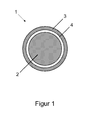
- Wire electrode 1 shown in cross-section has a core wire 2 which is completely surrounded by a jacket 3, 4 forming the outside of the wire electrode 1.
- the core 2 is formed homogeneously wholly or substantially entirely of copper or a copper-zinc alloy having a zinc content of preferably 2 to 40 wt.%.
- the jacket 3, 4 is consists of two superimposed partial or sheath layers 3 and 4, which are each formed to more than 50 wt.% And preferably completely or substantially completely made of brass.
- the outer jacket layer 3 is predominantly, i. to more than 50% by weight, and preferably completely or substantially wholly of a mixture of, for example, ⁇ and / or ⁇ '-brass and, secondly, ⁇ -brass, the ⁇ and / or ⁇ '-phase and the ⁇ -phase in a fine-grained structure are present side by side, in which the average grain size of the ⁇ and / or ⁇ '-brass grains and the ⁇ -brass grains, ie the grain size averaged over all belonging to the said phases grains perpendicular to the wire longitudinal axis is 0.1 to 5 microns.
- the further cladding layer 4 is between the cladding layer 3, which in the embodiment of FIG. 1 the outer surface of the wire electrode 1 forms, and the core 2 is arranged.
- the cladding layer 4 can advantageously predominantly, ie at least 50 wt.%, And preferably completely or substantially completely of ⁇ and / or ⁇ '-brass, ⁇ + ⁇ and / or ⁇ + ⁇ '-brass, ⁇ Brass and / or copper, with ⁇ - and / or ⁇ '-brass, ⁇ + ⁇ and / or ⁇ + ⁇ '-brass are preferred.
- the cladding layer 4 may also be advantageous to replace the cladding layer 4 by two cladding layers arranged one above the other, wherein the cladding layer adjoining the core is predominantly and preferably completely or essentially completely formed from ⁇ -brass and / or copper and the layer arranged above it Sheath layer is predominantly and preferably completely or substantially completely formed of ⁇ - and / or ⁇ '-brass, ⁇ + ⁇ - or ⁇ + ⁇ '-brass.
- a transition layer which also completely surrounds the core 2
- Such a transition layer serves for an improved connection between the core 2 and the cladding layer 4.
- a more or less extensive transition layer will generally already be inherent.
- Such a transition layer will have a small thickness compared to the sheath 3, 4.
- the interfaces between adjacent layers will generally not be ideally formed, but may be irregular and / or "out of focus" by diffusion processes.
- the course of the layers or of the boundary surfaces unlike in the drawings, depending on the production method, may also be so irregular that individual or several layers lying one above the other are "broken” in places by underlying layers or the core. become.
- the sheath 3, 4 and / or individual cladding layers 3, 4 and / or a possibly present transition layer can be designed such that they Have cracks or breaks and do not completely cover the core or underlying layers.
- the core 2 is formed of CuZn 37
- the cladding layer 4 adjacent to the core is formed predominantly of ⁇ - or ⁇ '-brass with a zinc content of about 48% by weight
- the cladding layer 3 forming the wire electrode 1 is predominantly formed from a phase mixture of ⁇ or ⁇ '-brass and ⁇ -brass with an average zinc content of about 55% by weight.
- the average layer thickness of the cladding layer 4 is about 8 .mu.m
- the average layer thickness of the cladding layer 3 is about 15 .mu.m
- the thickness of the entire wire electrode 1 is 0.25 mm.
- the wire electrode 1 has a tensile strength of about 800 N / mm 2 and an electrical conductivity of about 12 m / ⁇ mm 2 .
- a possible transition layer between the core and the sheath 3, 4 could for example have a thickness of about 1 micron.
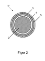
- FIG. 2 is a further preferred embodiment of a wire electrode 1 'shown in cross section.
- This embodiment differs in principle only by the embodiment according to FIG. 1 in that on the cladding layer 3, as the outermost cladding layer, there is still provided a cover layer 5 which is predominantly and preferably completely or essentially completely formed from zinc, a zinc alloy and / or zinc oxide. It should advantageously have a higher zinc content than the cladding layer 3 and can then favorably influence fine sizing operations with low discharge energies.
- the cover layer 5 may have a significantly smaller thickness than the cladding layer 3 and stronger interruptions. Possibly. Therefore, the outer surface of the wire electrode 1 'can be formed substantially by the cladding layer 3 and the cladding layer 5.
- the core 2 is made of CuZn 20
- the jacket layer 4 adjoining the core is formed predominantly of ⁇ or ⁇ '-brass with a zinc content of about 45% by weight
- the jacket layer 3 is predominantly composed of a phase mixture of ⁇ - and ⁇ -brass. or ⁇ '-brass and ⁇ -brass having an average zinc content of about 53 wt.% Formed
- the cover layer 5 consists predominantly of zinc oxide.
- the average layer thickness of the cladding layers 3 and 4 is about 12 .mu.m
- the average layer thickness of the cover layer 5 is about 1 .mu.m
- the thickness of the entire wire electrode 1 ' is 0.25 mm.
- the wire electrode 1 has a tensile strength of about 750 N / mm 2 and an electrical conductivity of about 17 M / ⁇ mm 2 .
- a possible transition layer between the core and the sheath 3, 4 could for example have a thickness of about 1 micron.
Landscapes
- Chemical & Material Sciences (AREA)
- Chemical Kinetics & Catalysis (AREA)
- Electrochemistry (AREA)
- Engineering & Computer Science (AREA)
- Mechanical Engineering (AREA)
- Electrical Discharge Machining, Electrochemical Machining, And Combined Machining (AREA)
Priority Applications (12)
| Application Number | Priority Date | Filing Date | Title |
|---|---|---|---|
| ES08170563T ES2390168T3 (es) | 2008-12-03 | 2008-12-03 | Electrodo de alambre para corte por descarga eléctrica y método para fabricar dicho electrodo de alambre |
| EP08170563.4A EP2193867B2 (fr) | 2008-12-03 | 2008-12-03 | Méthode de fabrication d'une électrode en fil d'acier destinée à la coupe par étincelage. |
| PL08170563T PL2193867T3 (pl) | 2008-12-03 | 2008-12-03 | Elektroda drutowa do cięcia elektroiskrowego i sposób wytwarzania takiej elektrody drutowej |
| PCT/EP2009/008435 WO2010063410A1 (fr) | 2008-12-03 | 2009-11-26 | Fil électrode pour découpage par électroérosion |
| BRPI0922696-6A BRPI0922696B1 (pt) | 2008-12-03 | 2009-11-26 | Eletrodo de fio para corte através de usinagem por descarga elétrica e método para a produção de um eletrodo de fio |
| JP2011538879A JP5744747B2 (ja) | 2008-12-03 | 2009-11-26 | 放電切断のためのワイヤ電極 |
| RU2011127209/02A RU2516125C2 (ru) | 2008-12-03 | 2009-11-26 | Проволочный электрод для электроэрозионной резки |
| US13/132,291 US8853587B2 (en) | 2008-12-03 | 2009-11-26 | Wire electrode for electrical discharge cutting |
| CA2745412A CA2745412C (fr) | 2008-12-03 | 2009-11-26 | Fil electrode pour decoupage par electroerosion |
| KR1020117014391A KR20110103971A (ko) | 2008-12-03 | 2009-11-26 | 전기 방전 절삭공정용 와이어 전극 |
| CN200980148686.6A CN102239024B (zh) | 2008-12-03 | 2009-11-26 | 电火花切割工艺用电极丝 |
| MX2011005839A MX2011005839A (es) | 2008-12-03 | 2009-11-26 | Electrodo de alambre para procesos de corte por descarga electrica. |
Applications Claiming Priority (1)
| Application Number | Priority Date | Filing Date | Title |
|---|---|---|---|
| EP08170563.4A EP2193867B2 (fr) | 2008-12-03 | 2008-12-03 | Méthode de fabrication d'une électrode en fil d'acier destinée à la coupe par étincelage. |
Publications (3)
| Publication Number | Publication Date |
|---|---|
| EP2193867A1 true EP2193867A1 (fr) | 2010-06-09 |
| EP2193867B1 EP2193867B1 (fr) | 2012-06-20 |
| EP2193867B2 EP2193867B2 (fr) | 2022-12-21 |
Family
ID=40599929
Family Applications (1)
| Application Number | Title | Priority Date | Filing Date |
|---|---|---|---|
| EP08170563.4A Active EP2193867B2 (fr) | 2008-12-03 | 2008-12-03 | Méthode de fabrication d'une électrode en fil d'acier destinée à la coupe par étincelage. |
Country Status (12)
| Country | Link |
|---|---|
| US (1) | US8853587B2 (fr) |
| EP (1) | EP2193867B2 (fr) |
| JP (1) | JP5744747B2 (fr) |
| KR (1) | KR20110103971A (fr) |
| CN (1) | CN102239024B (fr) |
| BR (1) | BRPI0922696B1 (fr) |
| CA (1) | CA2745412C (fr) |
| ES (1) | ES2390168T3 (fr) |
| MX (1) | MX2011005839A (fr) |
| PL (1) | PL2193867T3 (fr) |
| RU (1) | RU2516125C2 (fr) |
| WO (1) | WO2010063410A1 (fr) |
Cited By (2)
| Publication number | Priority date | Publication date | Assignee | Title |
|---|---|---|---|---|
| WO2013037336A1 (fr) | 2011-09-16 | 2013-03-21 | Heinrich Stamm Gmbh | Fil électrode utilisé pour la coupe par étincelage d'objets |
| WO2021198245A1 (fr) | 2020-03-31 | 2021-10-07 | Berkenhoff Gmbh | Électrode à fil pour découpe par électroérosion |
Families Citing this family (25)
| Publication number | Priority date | Publication date | Assignee | Title |
|---|---|---|---|---|
| JP4943827B2 (ja) * | 2006-11-30 | 2012-05-30 | 矢崎総業株式会社 | 抵抗溶接方法及び導体ユニット |
| EP2172295B1 (fr) | 2008-10-01 | 2012-06-20 | Berkenhoff GmbH | Fil électrode destiné à la coupe par étincelage |
| PL2193867T3 (pl) | 2008-12-03 | 2012-11-30 | Berkenhoff Gmbh | Elektroda drutowa do cięcia elektroiskrowego i sposób wytwarzania takiej elektrody drutowej |
| EP2517593B1 (fr) * | 2009-12-25 | 2015-11-11 | YKK Corporation | Composant de fermeture à glissière et fermeture à glissière avec curseur |
| KR101284495B1 (ko) * | 2011-04-29 | 2013-07-16 | 성기철 | 방전가공용 전극선 및 그 제조방법 |
| KR20140051734A (ko) * | 2012-10-23 | 2014-05-02 | 성기철 | 방전가공용 전극선 및 그 제조방법 |
| DE102013009767A1 (de) * | 2013-06-11 | 2014-12-11 | Heinrich Stamm Gmbh | Drahtelektrode zum funkenerosiven Schneiden von Gegenständen |
| CN103537768B (zh) * | 2013-11-12 | 2015-08-12 | 宁波博威麦特莱科技有限公司 | 慢走丝电火花放电加工用电极丝及其制备方法 |
| TW201545828A (zh) * | 2014-06-10 | 2015-12-16 | Ya-Yang Yan | 一種放電加工切割線及該放電加工切割線之製造方法 |
| CN104191056B (zh) * | 2014-08-13 | 2016-06-29 | 宁波博威麦特莱科技有限公司 | 一种高精度锌基合金电极丝及其制备方法 |
| JP6584765B2 (ja) | 2014-10-28 | 2019-10-02 | 沖電線株式会社 | 放電加工用電極線及び放電加工用電極線製造方法 |
| CN105312698B (zh) * | 2015-09-28 | 2017-10-31 | 宁波博德高科股份有限公司 | 低银氧单向走丝用电极丝及其制造方法 |
| CN105345184A (zh) * | 2015-11-23 | 2016-02-24 | 芜湖楚江合金铜材有限公司 | 一种低速电火花线切割复合铜合金线材及其制备方法 |
| CN106808037B (zh) * | 2015-12-02 | 2020-07-03 | 中国科学院宁波材料技术与工程研究所 | 仿鱼鳞微织构电极丝材料及其制备方法与应用 |
| JP6728915B2 (ja) * | 2016-04-11 | 2020-07-22 | 住友電気工業株式会社 | ワイヤ放電加工用電極線 |
| CN105834533B (zh) * | 2016-04-25 | 2017-12-01 | 宁波博德高科股份有限公司 | 用于慢走丝电火花切割用的电极丝 |
| EP3526354B1 (fr) * | 2016-10-14 | 2024-05-01 | Thermocompact | Fil d'edm revêtu d'un alliage |
| CA3042510A1 (fr) * | 2016-11-04 | 2018-05-11 | Global Innovative Products, Llc | Electrode pour fraisage electro-erosif |
| CN107671379A (zh) * | 2017-09-26 | 2018-02-09 | 宁波康强微电子技术有限公司 | 织构化镀层电极丝的制备方法 |
| CN108856935A (zh) * | 2018-07-18 | 2018-11-23 | 宁波正锦和精密贸易有限公司 | 放电加工用电极丝及其制造方法 |
| RU2694183C1 (ru) * | 2018-08-13 | 2019-07-09 | Федеральное государственное бюджетное учреждение науки Институт машиноведения им. А.А. Благонравова Российской академии наук (ИМАШ РАН) | Способ формирования высокоточного размера толщины электроэрозионной проволоки |
| US11511362B2 (en) * | 2019-02-05 | 2022-11-29 | Cap Technologies, Llc | Wire for electric discharge machining |
| BR112021022537A2 (pt) * | 2019-05-10 | 2021-12-28 | Berkenhoff Gmbh | Eletrodo de fio para corte de erosão por faíscas e método para a produção do dito eletrodo de fio |
| CN111590153B (zh) * | 2020-06-05 | 2021-09-17 | 宁波博德高科股份有限公司 | 一种微细电火花加工用电极丝、制备方法及应用 |
| CN113823435B (zh) * | 2021-09-08 | 2024-04-23 | 湖州金钛导体技术有限公司 | 一种复合电极丝、复合电极丝的制备方法及应用 |
Citations (9)
| Publication number | Priority date | Publication date | Assignee | Title |
|---|---|---|---|---|
| US4935594A (en) * | 1987-10-23 | 1990-06-19 | Berkenhoff Gmbh | Eroding electrode, in particular a wire electrode for the sparkerosive working |
| US4977303A (en) * | 1984-08-28 | 1990-12-11 | Charmilles Technologie S.A. | Zinc or cadmium coated, surface oxidized electrode wire for EDM cutting of a workpiece; and method for forming such a wire |
| EP0733431A1 (fr) * | 1995-03-24 | 1996-09-25 | Berkenhoff GmbH | Fil électrode et méthode de fabrication de l'électrode fil utilisé notamment pour usinage par décharges électriques |
| US5808262A (en) * | 1995-06-07 | 1998-09-15 | Swil Limited | Wire electrode for electro-discharge machining and method of manufacturing same |
| US5945010A (en) | 1997-09-02 | 1999-08-31 | Composite Concepts Company, Inc. | Electrode wire for use in electric discharge machining and process for preparing same |
| EP1038625A2 (fr) | 1999-03-25 | 2000-09-27 | Berkenhoff GmbH | Fil électrode |
| EP1295664A1 (fr) | 2001-09-21 | 2003-03-26 | Berkenhoff GmbH | Fil-électrode pour usinage par électroérosion |
| FR2881974A1 (fr) * | 2005-02-11 | 2006-08-18 | Thermocompact Sa | Fil composite pour electroerosion. |
| EP1949995A1 (fr) * | 2007-01-29 | 2008-07-30 | Thermocompact | Fil electrode pour electroerosion |
Family Cites Families (20)
| Publication number | Priority date | Publication date | Assignee | Title |
|---|---|---|---|---|
| US4686153A (en) | 1984-12-08 | 1987-08-11 | Fujikura Ltd. | Electrode wire for use in electric discharge machining and process for preparing same |
| US4713216A (en) | 1985-04-27 | 1987-12-15 | Showa Aluminum Kabushiki Kaisha | Aluminum alloys having high strength and resistance to stress and corrosion |
| JPS62148121A (ja) | 1985-12-20 | 1987-07-02 | Sumitomo Electric Ind Ltd | 放電加工用カツトワイヤ |
| KR920010862B1 (ko) | 1988-06-30 | 1992-12-19 | 미쯔비시 덴끼 가부시기가이샤 | 와이어컷방전 가공용 와이어전극 |
| JPH0755407B2 (ja) | 1992-12-18 | 1995-06-14 | 株式会社フジクラ | ワイヤ放電加工用電極線の製造方法 |
| US5762726A (en) | 1995-03-24 | 1998-06-09 | Berkenhoff Gmbh | Wire electrode and process for producing a wire electrode, particular for a spark erosion process |
| FR2732251B1 (fr) | 1995-03-27 | 1997-05-30 | Thermocompact Sa | Procede et dispositif pour la fabrication de fil electrode pour etincelage erosif, et fil ainsi obtenu |
| FR2778489B1 (fr) | 1998-05-07 | 2006-05-12 | Thermocompact Sa | Procede et dispositif pour la fabrication d'un fil electrode pour electroerosion |
| JP2001052528A (ja) | 1999-08-06 | 2001-02-23 | Furukawa Electric Co Ltd:The | 高導電性ワイヤ放電加工用電極線 |
| JP2002126949A (ja) * | 2000-10-23 | 2002-05-08 | Sumitomo Metal Mining Co Ltd | ワイヤ放電加工用電極線 |
| JP2002137123A (ja) * | 2000-10-31 | 2002-05-14 | Oki Electric Cable Co Ltd | ワイヤ放電加工用電極線 |
| US6676899B2 (en) | 2000-12-21 | 2004-01-13 | Eads Deutschland Gmbh | Non-hardenable aluminum alloy as a semi-finished product for structures |
| DE50112526D1 (de) | 2001-09-21 | 2007-07-05 | Berkenhoff Gmbh | Drahtelektrode mit strukturierter Grenzfläche |
| FR2833875B1 (fr) | 2001-12-21 | 2004-07-02 | Thermocompact Sa | Fil pour electroerosion a grande vitesse d'usinage |
| JP2005254408A (ja) | 2004-03-12 | 2005-09-22 | Sumitomo Electric Ind Ltd | ワイヤ放電加工用電極線およびその製造方法 |
| FR2881973B1 (fr) * | 2005-02-11 | 2007-05-11 | Thermocompact Sa | Fil composite pour electrosion |
| KR100543847B1 (ko) † | 2005-04-01 | 2006-01-20 | 주식회사 엠에이씨티 | 방전가공용 전극선 및 그 제조 방법 |
| WO2007064646A2 (fr) | 2005-12-01 | 2007-06-07 | Composite Concepts Company Et Al. | Fil d'electroerosion |
| EP2172295B1 (fr) | 2008-10-01 | 2012-06-20 | Berkenhoff GmbH | Fil électrode destiné à la coupe par étincelage |
| PL2193867T3 (pl) | 2008-12-03 | 2012-11-30 | Berkenhoff Gmbh | Elektroda drutowa do cięcia elektroiskrowego i sposób wytwarzania takiej elektrody drutowej |
-
2008
- 2008-12-03 PL PL08170563T patent/PL2193867T3/pl unknown
- 2008-12-03 ES ES08170563T patent/ES2390168T3/es active Active
- 2008-12-03 EP EP08170563.4A patent/EP2193867B2/fr active Active
-
2009
- 2009-11-26 RU RU2011127209/02A patent/RU2516125C2/ru active
- 2009-11-26 MX MX2011005839A patent/MX2011005839A/es active IP Right Grant
- 2009-11-26 JP JP2011538879A patent/JP5744747B2/ja active Active
- 2009-11-26 CA CA2745412A patent/CA2745412C/fr active Active
- 2009-11-26 CN CN200980148686.6A patent/CN102239024B/zh active Active
- 2009-11-26 US US13/132,291 patent/US8853587B2/en active Active
- 2009-11-26 WO PCT/EP2009/008435 patent/WO2010063410A1/fr active Application Filing
- 2009-11-26 BR BRPI0922696-6A patent/BRPI0922696B1/pt not_active IP Right Cessation
- 2009-11-26 KR KR1020117014391A patent/KR20110103971A/ko not_active Application Discontinuation
Patent Citations (11)
| Publication number | Priority date | Publication date | Assignee | Title |
|---|---|---|---|---|
| US4977303A (en) * | 1984-08-28 | 1990-12-11 | Charmilles Technologie S.A. | Zinc or cadmium coated, surface oxidized electrode wire for EDM cutting of a workpiece; and method for forming such a wire |
| US4935594A (en) * | 1987-10-23 | 1990-06-19 | Berkenhoff Gmbh | Eroding electrode, in particular a wire electrode for the sparkerosive working |
| US4935594B1 (en) * | 1987-10-23 | 2000-01-04 | Berkenhoff Gmbh | Encoding electrode in particular a wire electrode for the sparkerosive working |
| EP0733431A1 (fr) * | 1995-03-24 | 1996-09-25 | Berkenhoff GmbH | Fil électrode et méthode de fabrication de l'électrode fil utilisé notamment pour usinage par décharges électriques |
| EP0733431B1 (fr) | 1995-03-24 | 1999-05-19 | Berkenhoff GmbH | Fil électrode et méthode de fabrication de l'électrode fil utilisé notamment pour usinage par décharges électriques |
| US5808262A (en) * | 1995-06-07 | 1998-09-15 | Swil Limited | Wire electrode for electro-discharge machining and method of manufacturing same |
| US5945010A (en) | 1997-09-02 | 1999-08-31 | Composite Concepts Company, Inc. | Electrode wire for use in electric discharge machining and process for preparing same |
| EP1038625A2 (fr) | 1999-03-25 | 2000-09-27 | Berkenhoff GmbH | Fil électrode |
| EP1295664A1 (fr) | 2001-09-21 | 2003-03-26 | Berkenhoff GmbH | Fil-électrode pour usinage par électroérosion |
| FR2881974A1 (fr) * | 2005-02-11 | 2006-08-18 | Thermocompact Sa | Fil composite pour electroerosion. |
| EP1949995A1 (fr) * | 2007-01-29 | 2008-07-30 | Thermocompact | Fil electrode pour electroerosion |
Cited By (4)
| Publication number | Priority date | Publication date | Assignee | Title |
|---|---|---|---|---|
| WO2013037336A1 (fr) | 2011-09-16 | 2013-03-21 | Heinrich Stamm Gmbh | Fil électrode utilisé pour la coupe par étincelage d'objets |
| US10583509B2 (en) | 2011-09-16 | 2020-03-10 | Heinrich Stamm Gmbh | Wire electrode for the spark-erosive cutting of articles |
| WO2021198245A1 (fr) | 2020-03-31 | 2021-10-07 | Berkenhoff Gmbh | Électrode à fil pour découpe par électroérosion |
| KR20220163992A (ko) | 2020-03-31 | 2022-12-12 | 베르켄호프 게엠베하 | 스파크-침식 절단용 와이어 전극 |
Also Published As
| Publication number | Publication date |
|---|---|
| EP2193867B1 (fr) | 2012-06-20 |
| CN102239024B (zh) | 2014-11-05 |
| BRPI0922696B1 (pt) | 2019-10-08 |
| CA2745412C (fr) | 2017-02-07 |
| RU2011127209A (ru) | 2013-01-10 |
| KR20110103971A (ko) | 2011-09-21 |
| RU2516125C2 (ru) | 2014-05-20 |
| US8853587B2 (en) | 2014-10-07 |
| BRPI0922696A2 (pt) | 2016-01-05 |
| JP5744747B2 (ja) | 2015-07-08 |
| EP2193867B2 (fr) | 2022-12-21 |
| CN102239024A (zh) | 2011-11-09 |
| ES2390168T3 (es) | 2012-11-07 |
| PL2193867T3 (pl) | 2012-11-30 |
| MX2011005839A (es) | 2011-09-22 |
| CA2745412A1 (fr) | 2010-06-10 |
| JP2012510378A (ja) | 2012-05-10 |
| US20110290531A1 (en) | 2011-12-01 |
| WO2010063410A1 (fr) | 2010-06-10 |
Similar Documents
| Publication | Publication Date | Title |
|---|---|---|
| EP2193867B1 (fr) | Electrode en fil d'acier destinée à la coupe par étincelage et méthode de fabrication d'une telle électrode. | |
| DE69813840T3 (de) | Drahtelektrode für funkerosionsbearbeitung und verfahren zur herstellung derselben | |
| EP2172295B1 (fr) | Fil électrode destiné à la coupe par étincelage | |
| DE2906245C3 (de) | Drahtelektrode für das funkenerosive Schneiden | |
| EP0312674B1 (fr) | Electrode d'érosion, en particulier fil électrode pour usinage par étincelles | |
| EP1295664B1 (fr) | Fil-électrode pour usinage par électroérosion | |
| DE60206413T2 (de) | Draht für hochgeschwindigkeitsfunkenerosion | |
| EP2163661B1 (fr) | Outil de fraisage à cylindre pourvu d'un revêtement et procédé de nouveau revêtement d'un outil de fraisage à cylindre | |
| EP3425665B1 (fr) | Procédé de fabrication d'un fils de connexion | |
| EP3109889B1 (fr) | Anode rotative de tube a rayons x | |
| DE3035058A1 (de) | Drahtelektrode zum schneiden metallischer werkstuecke durch funkenerosion sowie verwendung und verwendung zur herstellung solcher drahtelektroden | |
| EP0733431B1 (fr) | Fil électrode et méthode de fabrication de l'électrode fil utilisé notamment pour usinage par décharges électriques | |
| WO2020229365A1 (fr) | Fil-électrode pour découpage par électro-érosion et procédé pour la fabrication dudit fil-électrode | |
| CH667469A5 (de) | Verfahren zum aufbringen von schutzschichten. | |
| DE2638680A1 (de) | Supraleitender verbundkoerper und verfahren zu dessen herstellung | |
| EP2755792B1 (fr) | Fil électrode utilisé pour la coupe par étincelage d'objets | |
| DE112015004895B4 (de) | Elektrodendraht für Erodierverarbeitung und Verfahren zum Herstellen eines Elektrodendrahts für Erodierverarbeitung | |
| WO2014198254A1 (fr) | Fil-électrode servant à la coupe d'objets par électroérosion | |
| DE60032548T2 (de) | Drahtelektrode zum funkenerosiven Schneiden | |
| EP3017079B1 (fr) | Procédé de production de couches de tixsi1-xn | |
| EP3862759A1 (fr) | Fil enrobe et procédé de fabrication de fil enrobe | |
| DE4026607A1 (de) | Verfahren zur erhoehung der standzeit eines werkzeuges zum schaelen von straengen und draehten aus aluminium | |
| DE102015210460A1 (de) | Elektrisches Kontaktelement sowie Verfahren zur Veränderung mechanischer und/oder elektrischer Eigenschaften zumindest eines Bereichs eines solchen | |
| EP4028194A1 (fr) | Électrode à fil pour découpe par électroérosion | |
| DE112017001794T5 (de) | Sinterkörper auf Siliziumnitridbasis und Schneideinsatz |
Legal Events
| Date | Code | Title | Description |
|---|---|---|---|
| PUAI | Public reference made under article 153(3) epc to a published international application that has entered the european phase |
Free format text: ORIGINAL CODE: 0009012 |
|
| AK | Designated contracting states |
Kind code of ref document: A1 Designated state(s): AT BE BG CH CY CZ DE DK EE ES FI FR GB GR HR HU IE IS IT LI LT LU LV MC MT NL NO PL PT RO SE SI SK TR |
|
| AX | Request for extension of the european patent |
Extension state: AL BA MK RS |
|
| 17P | Request for examination filed |
Effective date: 20101208 |
|
| AKX | Designation fees paid |
Designated state(s): AT BE BG CH CY CZ DE DK EE ES FI FR GB GR HR HU IE IS IT LI LT LU LV MC MT NL NO PL PT RO SE SI SK TR |
|
| GRAP | Despatch of communication of intention to grant a patent |
Free format text: ORIGINAL CODE: EPIDOSNIGR1 |
|
| RTI1 | Title (correction) |
Free format text: WIRE ELECTRODES FOR ELECTRICAL DISCHARGE CUTTING AND METHOD FOR MANUFACTURING SUCH A WIRE ELECTRODE. |
|
| GRAS | Grant fee paid |
Free format text: ORIGINAL CODE: EPIDOSNIGR3 |
|
| GRAA | (expected) grant |
Free format text: ORIGINAL CODE: 0009210 |
|
| STAA | Information on the status of an ep patent application or granted ep patent |
Free format text: STATUS: THE PATENT HAS BEEN GRANTED |
|
| AK | Designated contracting states |
Kind code of ref document: B1 Designated state(s): AT BE BG CH CY CZ DE DK EE ES FI FR GB GR HR HU IE IS IT LI LT LU LV MC MT NL NO PL PT RO SE SI SK TR |
|
| REG | Reference to a national code |
Ref country code: GB Ref legal event code: FG4D Free format text: NOT ENGLISH |
|
| REG | Reference to a national code |
Ref country code: CH Ref legal event code: EP |
|
| REG | Reference to a national code |
Ref country code: AT Ref legal event code: REF Ref document number: 562741 Country of ref document: AT Kind code of ref document: T Effective date: 20120715 |
|
| REG | Reference to a national code |
Ref country code: IE Ref legal event code: FG4D Free format text: LANGUAGE OF EP DOCUMENT: GERMAN |
|
| REG | Reference to a national code |
Ref country code: DE Ref legal event code: R096 Ref document number: 502008007471 Country of ref document: DE Effective date: 20120816 |
|
| REG | Reference to a national code |
Ref country code: CH Ref legal event code: NV Representative=s name: R. A. EGLI & CO. PATENTANWAELTE |
|
| REG | Reference to a national code |
Ref country code: SE Ref legal event code: TRGR |
|
| REG | Reference to a national code |
Ref country code: NL Ref legal event code: T3 |
|
| PG25 | Lapsed in a contracting state [announced via postgrant information from national office to epo] |
Ref country code: LT Free format text: LAPSE BECAUSE OF FAILURE TO SUBMIT A TRANSLATION OF THE DESCRIPTION OR TO PAY THE FEE WITHIN THE PRESCRIBED TIME-LIMIT Effective date: 20120620 Ref country code: NO Free format text: LAPSE BECAUSE OF FAILURE TO SUBMIT A TRANSLATION OF THE DESCRIPTION OR TO PAY THE FEE WITHIN THE PRESCRIBED TIME-LIMIT Effective date: 20120920 Ref country code: FI Free format text: LAPSE BECAUSE OF FAILURE TO SUBMIT A TRANSLATION OF THE DESCRIPTION OR TO PAY THE FEE WITHIN THE PRESCRIBED TIME-LIMIT Effective date: 20120620 |
|
| REG | Reference to a national code |
Ref country code: ES Ref legal event code: FG2A Ref document number: 2390168 Country of ref document: ES Kind code of ref document: T3 Effective date: 20121107 |
|
| REG | Reference to a national code |
Ref country code: LT Ref legal event code: MG4D Effective date: 20120620 |
|
| PG25 | Lapsed in a contracting state [announced via postgrant information from national office to epo] |
Ref country code: HR Free format text: LAPSE BECAUSE OF FAILURE TO SUBMIT A TRANSLATION OF THE DESCRIPTION OR TO PAY THE FEE WITHIN THE PRESCRIBED TIME-LIMIT Effective date: 20120620 Ref country code: GR Free format text: LAPSE BECAUSE OF FAILURE TO SUBMIT A TRANSLATION OF THE DESCRIPTION OR TO PAY THE FEE WITHIN THE PRESCRIBED TIME-LIMIT Effective date: 20120921 Ref country code: LV Free format text: LAPSE BECAUSE OF FAILURE TO SUBMIT A TRANSLATION OF THE DESCRIPTION OR TO PAY THE FEE WITHIN THE PRESCRIBED TIME-LIMIT Effective date: 20120620 Ref country code: SI Free format text: LAPSE BECAUSE OF FAILURE TO SUBMIT A TRANSLATION OF THE DESCRIPTION OR TO PAY THE FEE WITHIN THE PRESCRIBED TIME-LIMIT Effective date: 20120620 |
|
| REG | Reference to a national code |
Ref country code: PL Ref legal event code: T3 |
|
| PG25 | Lapsed in a contracting state [announced via postgrant information from national office to epo] |
Ref country code: EE Free format text: LAPSE BECAUSE OF FAILURE TO SUBMIT A TRANSLATION OF THE DESCRIPTION OR TO PAY THE FEE WITHIN THE PRESCRIBED TIME-LIMIT Effective date: 20120620 Ref country code: CY Free format text: LAPSE BECAUSE OF FAILURE TO SUBMIT A TRANSLATION OF THE DESCRIPTION OR TO PAY THE FEE WITHIN THE PRESCRIBED TIME-LIMIT Effective date: 20120620 Ref country code: RO Free format text: LAPSE BECAUSE OF FAILURE TO SUBMIT A TRANSLATION OF THE DESCRIPTION OR TO PAY THE FEE WITHIN THE PRESCRIBED TIME-LIMIT Effective date: 20120620 Ref country code: IS Free format text: LAPSE BECAUSE OF FAILURE TO SUBMIT A TRANSLATION OF THE DESCRIPTION OR TO PAY THE FEE WITHIN THE PRESCRIBED TIME-LIMIT Effective date: 20121020 Ref country code: SK Free format text: LAPSE BECAUSE OF FAILURE TO SUBMIT A TRANSLATION OF THE DESCRIPTION OR TO PAY THE FEE WITHIN THE PRESCRIBED TIME-LIMIT Effective date: 20120620 |
|
| PG25 | Lapsed in a contracting state [announced via postgrant information from national office to epo] |
Ref country code: PT Free format text: LAPSE BECAUSE OF FAILURE TO SUBMIT A TRANSLATION OF THE DESCRIPTION OR TO PAY THE FEE WITHIN THE PRESCRIBED TIME-LIMIT Effective date: 20121022 |
|
| PLBI | Opposition filed |
Free format text: ORIGINAL CODE: 0009260 |
|
| PLBI | Opposition filed |
Free format text: ORIGINAL CODE: 0009260 |
|
| 26 | Opposition filed |
Opponent name: HEINRICH STAMM GMBH Effective date: 20130315 |
|
| PG25 | Lapsed in a contracting state [announced via postgrant information from national office to epo] |
Ref country code: DK Free format text: LAPSE BECAUSE OF FAILURE TO SUBMIT A TRANSLATION OF THE DESCRIPTION OR TO PAY THE FEE WITHIN THE PRESCRIBED TIME-LIMIT Effective date: 20120620 |
|
| 26 | Opposition filed |
Opponent name: OPECMADE, INC. Effective date: 20130320 Opponent name: EDM, MART CO., LTD Effective date: 20130320 Opponent name: THERMOCOMPACT Effective date: 20130320 |
|
| PLAX | Notice of opposition and request to file observation + time limit sent |
Free format text: ORIGINAL CODE: EPIDOSNOBS2 |
|
| REG | Reference to a national code |
Ref country code: DE Ref legal event code: R026 Ref document number: 502008007471 Country of ref document: DE Effective date: 20130315 |
|
| PG25 | Lapsed in a contracting state [announced via postgrant information from national office to epo] |
Ref country code: BG Free format text: LAPSE BECAUSE OF FAILURE TO SUBMIT A TRANSLATION OF THE DESCRIPTION OR TO PAY THE FEE WITHIN THE PRESCRIBED TIME-LIMIT Effective date: 20120920 Ref country code: MC Free format text: LAPSE BECAUSE OF NON-PAYMENT OF DUE FEES Effective date: 20121231 |
|
| PLAF | Information modified related to communication of a notice of opposition and request to file observations + time limit |
Free format text: ORIGINAL CODE: EPIDOSCOBS2 |
|
| REG | Reference to a national code |
Ref country code: IE Ref legal event code: MM4A |
|
| PG25 | Lapsed in a contracting state [announced via postgrant information from national office to epo] |
Ref country code: IE Free format text: LAPSE BECAUSE OF NON-PAYMENT OF DUE FEES Effective date: 20121203 |
|
| PLBB | Reply of patent proprietor to notice(s) of opposition received |
Free format text: ORIGINAL CODE: EPIDOSNOBS3 |
|
| PG25 | Lapsed in a contracting state [announced via postgrant information from national office to epo] |
Ref country code: MT Free format text: LAPSE BECAUSE OF FAILURE TO SUBMIT A TRANSLATION OF THE DESCRIPTION OR TO PAY THE FEE WITHIN THE PRESCRIBED TIME-LIMIT Effective date: 20120620 |
|
| PGFP | Annual fee paid to national office [announced via postgrant information from national office to epo] |
Ref country code: TR Payment date: 20131128 Year of fee payment: 6 |
|
| PLBP | Opposition withdrawn |
Free format text: ORIGINAL CODE: 0009264 |
|
| PG25 | Lapsed in a contracting state [announced via postgrant information from national office to epo] |
Ref country code: LU Free format text: LAPSE BECAUSE OF NON-PAYMENT OF DUE FEES Effective date: 20121203 |
|
| PG25 | Lapsed in a contracting state [announced via postgrant information from national office to epo] |
Ref country code: HU Free format text: LAPSE BECAUSE OF FAILURE TO SUBMIT A TRANSLATION OF THE DESCRIPTION OR TO PAY THE FEE WITHIN THE PRESCRIBED TIME-LIMIT Effective date: 20081203 |
|
| PGFP | Annual fee paid to national office [announced via postgrant information from national office to epo] |
Ref country code: ES Payment date: 20141111 Year of fee payment: 7 Ref country code: SE Payment date: 20141211 Year of fee payment: 7 Ref country code: CZ Payment date: 20141113 Year of fee payment: 7 |
|
| PGFP | Annual fee paid to national office [announced via postgrant information from national office to epo] |
Ref country code: PL Payment date: 20141113 Year of fee payment: 7 Ref country code: NL Payment date: 20141210 Year of fee payment: 7 Ref country code: AT Payment date: 20141125 Year of fee payment: 7 |
|
| PGFP | Annual fee paid to national office [announced via postgrant information from national office to epo] |
Ref country code: BE Payment date: 20141211 Year of fee payment: 7 |
|
| PLAB | Opposition data, opponent's data or that of the opponent's representative modified |
Free format text: ORIGINAL CODE: 0009299OPPO |
|
| R26 | Opposition filed (corrected) |
Opponent name: HEINRICH STAMM GMBH Effective date: 20130315 |
|
| RDAF | Communication despatched that patent is revoked |
Free format text: ORIGINAL CODE: EPIDOSNREV1 |
|
| PLAB | Opposition data, opponent's data or that of the opponent's representative modified |
Free format text: ORIGINAL CODE: 0009299OPPO |
|
| APBM | Appeal reference recorded |
Free format text: ORIGINAL CODE: EPIDOSNREFNO |
|
| APBP | Date of receipt of notice of appeal recorded |
Free format text: ORIGINAL CODE: EPIDOSNNOA2O |
|
| APAH | Appeal reference modified |
Free format text: ORIGINAL CODE: EPIDOSCREFNO |
|
| REG | Reference to a national code |
Ref country code: FR Ref legal event code: PLFP Year of fee payment: 8 |
|
| PG25 | Lapsed in a contracting state [announced via postgrant information from national office to epo] |
Ref country code: BE Free format text: LAPSE BECAUSE OF NON-PAYMENT OF DUE FEES Effective date: 20151231 |
|
| PG25 | Lapsed in a contracting state [announced via postgrant information from national office to epo] |
Ref country code: CZ Free format text: LAPSE BECAUSE OF NON-PAYMENT OF DUE FEES Effective date: 20151203 |
|
| REG | Reference to a national code |
Ref country code: SE Ref legal event code: EUG |
|
| REG | Reference to a national code |
Ref country code: AT Ref legal event code: MM01 Ref document number: 562741 Country of ref document: AT Kind code of ref document: T Effective date: 20151203 |
|
| PG25 | Lapsed in a contracting state [announced via postgrant information from national office to epo] |
Ref country code: SE Free format text: LAPSE BECAUSE OF NON-PAYMENT OF DUE FEES Effective date: 20151204 |
|
| REG | Reference to a national code |
Ref country code: NL Ref legal event code: MM Effective date: 20160101 |
|
| PG25 | Lapsed in a contracting state [announced via postgrant information from national office to epo] |
Ref country code: NL Free format text: LAPSE BECAUSE OF NON-PAYMENT OF DUE FEES Effective date: 20160101 |
|
| REG | Reference to a national code |
Ref country code: FR Ref legal event code: PLFP Year of fee payment: 9 |
|
| PG25 | Lapsed in a contracting state [announced via postgrant information from national office to epo] |
Ref country code: AT Free format text: LAPSE BECAUSE OF NON-PAYMENT OF DUE FEES Effective date: 20151203 |
|
| REG | Reference to a national code |
Ref country code: ES Ref legal event code: FD2A Effective date: 20170126 |
|
| PG25 | Lapsed in a contracting state [announced via postgrant information from national office to epo] |
Ref country code: ES Free format text: LAPSE BECAUSE OF NON-PAYMENT OF DUE FEES Effective date: 20151204 |
|
| PG25 | Lapsed in a contracting state [announced via postgrant information from national office to epo] |
Ref country code: PL Free format text: LAPSE BECAUSE OF NON-PAYMENT OF DUE FEES Effective date: 20151203 |
|
| PG25 | Lapsed in a contracting state [announced via postgrant information from national office to epo] |
Ref country code: TR Free format text: LAPSE BECAUSE OF NON-PAYMENT OF DUE FEES Effective date: 20151203 |
|
| REG | Reference to a national code |
Ref country code: FR Ref legal event code: PLFP Year of fee payment: 10 |
|
| PLAB | Opposition data, opponent's data or that of the opponent's representative modified |
Free format text: ORIGINAL CODE: 0009299OPPO |
|
| R26 | Opposition filed (corrected) |
Opponent name: HEINRICH STAMM GMBH Effective date: 20130315 |
|
| PLAB | Opposition data, opponent's data or that of the opponent's representative modified |
Free format text: ORIGINAL CODE: 0009299OPPO |
|
| APBU | Appeal procedure closed |
Free format text: ORIGINAL CODE: EPIDOSNNOA9O |
|
| R26 | Opposition filed (corrected) |
Opponent name: EDM, MART CO., LTD Effective date: 20130320 |
|
| PUAJ | Public notification under rule 129 epc |
Free format text: ORIGINAL CODE: 0009425 |
|
| 32PN | Public notification |
Free format text: ENTSCHEIDUNG DER TECHNISCHEN BESCHWERDEKAMMER 3.2.08 VOM 6. MAERZ 2019 |
|
| REG | Reference to a national code |
Ref country code: CH Ref legal event code: PL |
|
| PG25 | Lapsed in a contracting state [announced via postgrant information from national office to epo] |
Ref country code: LI Free format text: LAPSE BECAUSE OF NON-PAYMENT OF DUE FEES Effective date: 20191231 Ref country code: CH Free format text: LAPSE BECAUSE OF NON-PAYMENT OF DUE FEES Effective date: 20191231 |
|
| REG | Reference to a national code |
Ref country code: CH Ref legal event code: PK Free format text: TITEL |
|
| PUAH | Patent maintained in amended form |
Free format text: ORIGINAL CODE: 0009272 |
|
| STAA | Information on the status of an ep patent application or granted ep patent |
Free format text: STATUS: PATENT MAINTAINED AS AMENDED |
|
| 27A | Patent maintained in amended form |
Effective date: 20221221 |
|
| AK | Designated contracting states |
Kind code of ref document: B2 Designated state(s): AT BE BG CH CY CZ DE DK EE ES FI FR GB GR HR HU IE IS IT LI LT LU LV MC MT NL NO PL PT RO SE SI SK TR |
|
| REG | Reference to a national code |
Ref country code: DE Ref legal event code: R102 Ref document number: 502008007471 Country of ref document: DE |
|
| PGFP | Annual fee paid to national office [announced via postgrant information from national office to epo] |
Ref country code: IT Payment date: 20221111 Year of fee payment: 15 |
|
| PGFP | Annual fee paid to national office [announced via postgrant information from national office to epo] |
Ref country code: GB Payment date: 20231220 Year of fee payment: 16 |
|
| PGFP | Annual fee paid to national office [announced via postgrant information from national office to epo] |
Ref country code: FR Payment date: 20231220 Year of fee payment: 16 Ref country code: DE Payment date: 20231214 Year of fee payment: 16 |