EP2193703A1 - Safety device based on a presence of the operator on the seat of a tractor - Google Patents
Safety device based on a presence of the operator on the seat of a tractor Download PDFInfo
- Publication number
- EP2193703A1 EP2193703A1 EP09177766A EP09177766A EP2193703A1 EP 2193703 A1 EP2193703 A1 EP 2193703A1 EP 09177766 A EP09177766 A EP 09177766A EP 09177766 A EP09177766 A EP 09177766A EP 2193703 A1 EP2193703 A1 EP 2193703A1
- Authority
- EP
- European Patent Office
- Prior art keywords
- operator
- support
- seat
- switch
- mobile
- Prior art date
- Legal status (The legal status is an assumption and is not a legal conclusion. Google has not performed a legal analysis and makes no representation as to the accuracy of the status listed.)
- Granted
Links
- 239000006096 absorbing agent Substances 0.000 claims abstract description 4
- 230000037431 insertion Effects 0.000 claims abstract description 4
- 238000003780 insertion Methods 0.000 claims abstract description 4
- 230000035939 shock Effects 0.000 claims abstract description 4
- 230000008878 coupling Effects 0.000 claims description 2
- 238000010168 coupling process Methods 0.000 claims description 2
- 238000005859 coupling reaction Methods 0.000 claims description 2
- 230000001681 protective effect Effects 0.000 claims description 2
- 230000002441 reversible effect Effects 0.000 abstract description 3
- 239000000428 dust Substances 0.000 description 1
- 125000006850 spacer group Chemical group 0.000 description 1
- 238000005303 weighing Methods 0.000 description 1
Images


Classifications
-
- A—HUMAN NECESSITIES
- A01—AGRICULTURE; FORESTRY; ANIMAL HUSBANDRY; HUNTING; TRAPPING; FISHING
- A01D—HARVESTING; MOWING
- A01D34/00—Mowers; Mowing apparatus of harvesters
- A01D34/01—Mowers; Mowing apparatus of harvesters characterised by features relating to the type of cutting apparatus
- A01D34/412—Mowers; Mowing apparatus of harvesters characterised by features relating to the type of cutting apparatus having rotating cutters
- A01D34/63—Mowers; Mowing apparatus of harvesters characterised by features relating to the type of cutting apparatus having rotating cutters having cutters rotating about a vertical axis
- A01D34/82—Other details
- A01D34/828—Safety devices
-
- A—HUMAN NECESSITIES
- A01—AGRICULTURE; FORESTRY; ANIMAL HUSBANDRY; HUNTING; TRAPPING; FISHING
- A01D—HARVESTING; MOWING
- A01D75/00—Accessories for harvesters or mowers
- A01D75/20—Devices for protecting men or animals
-
- B—PERFORMING OPERATIONS; TRANSPORTING
- B60—VEHICLES IN GENERAL
- B60K—ARRANGEMENT OR MOUNTING OF PROPULSION UNITS OR OF TRANSMISSIONS IN VEHICLES; ARRANGEMENT OR MOUNTING OF PLURAL DIVERSE PRIME-MOVERS IN VEHICLES; AUXILIARY DRIVES FOR VEHICLES; INSTRUMENTATION OR DASHBOARDS FOR VEHICLES; ARRANGEMENTS IN CONNECTION WITH COOLING, AIR INTAKE, GAS EXHAUST OR FUEL SUPPLY OF PROPULSION UNITS IN VEHICLES
- B60K28/00—Safety devices for propulsion-unit control, specially adapted for, or arranged in, vehicles, e.g. preventing fuel supply or ignition in the event of potentially dangerous conditions
- B60K28/02—Safety devices for propulsion-unit control, specially adapted for, or arranged in, vehicles, e.g. preventing fuel supply or ignition in the event of potentially dangerous conditions responsive to conditions relating to the driver
- B60K28/06—Safety devices for propulsion-unit control, specially adapted for, or arranged in, vehicles, e.g. preventing fuel supply or ignition in the event of potentially dangerous conditions responsive to conditions relating to the driver responsive to incapacity of driver
- B60K28/063—Safety devices for propulsion-unit control, specially adapted for, or arranged in, vehicles, e.g. preventing fuel supply or ignition in the event of potentially dangerous conditions responsive to conditions relating to the driver responsive to incapacity of driver preventing starting of vehicles
-
- B—PERFORMING OPERATIONS; TRANSPORTING
- B60—VEHICLES IN GENERAL
- B60N—SEATS SPECIALLY ADAPTED FOR VEHICLES; VEHICLE PASSENGER ACCOMMODATION NOT OTHERWISE PROVIDED FOR
- B60N2/00—Seats specially adapted for vehicles; Arrangement or mounting of seats in vehicles
- B60N2/002—Seats provided with an occupancy detection means mounted therein or thereon
-
- B—PERFORMING OPERATIONS; TRANSPORTING
- B60—VEHICLES IN GENERAL
- B60N—SEATS SPECIALLY ADAPTED FOR VEHICLES; VEHICLE PASSENGER ACCOMMODATION NOT OTHERWISE PROVIDED FOR
- B60N2/00—Seats specially adapted for vehicles; Arrangement or mounting of seats in vehicles
- B60N2/24—Seats specially adapted for vehicles; Arrangement or mounting of seats in vehicles for particular purposes or particular vehicles
- B60N2/38—Seats specially adapted for vehicles; Arrangement or mounting of seats in vehicles for particular purposes or particular vehicles specially constructed for use on tractors or like off-road vehicles
-
- B—PERFORMING OPERATIONS; TRANSPORTING
- B60—VEHICLES IN GENERAL
- B60N—SEATS SPECIALLY ADAPTED FOR VEHICLES; VEHICLE PASSENGER ACCOMMODATION NOT OTHERWISE PROVIDED FOR
- B60N2/00—Seats specially adapted for vehicles; Arrangement or mounting of seats in vehicles
- B60N2/50—Seat suspension devices
- B60N2/502—Seat suspension devices attached to the base of the seat
-
- B—PERFORMING OPERATIONS; TRANSPORTING
- B60—VEHICLES IN GENERAL
- B60N—SEATS SPECIALLY ADAPTED FOR VEHICLES; VEHICLE PASSENGER ACCOMMODATION NOT OTHERWISE PROVIDED FOR
- B60N2/00—Seats specially adapted for vehicles; Arrangement or mounting of seats in vehicles
- B60N2/50—Seat suspension devices
- B60N2/54—Seat suspension devices using mechanical springs
- B60N2/544—Compression or tension springs
-
- A—HUMAN NECESSITIES
- A01—AGRICULTURE; FORESTRY; ANIMAL HUSBANDRY; HUNTING; TRAPPING; FISHING
- A01D—HARVESTING; MOWING
- A01D67/00—Undercarriages or frames specially adapted for harvesters or mowers; Mechanisms for adjusting the frame; Platforms
- A01D67/04—Seats
Definitions
- the present invention concerns a safety device based on the presence of the operator on the seat of a tractor, in particular a tractor mower,
- the presence device of the operator on the seat is the most important unit on the tractor in terms of safety.
- Safety devices are known with switches located underneath the seat, that require adjustments, or switches inside the seat, both easily accessible for the operator, including the power leads that can be so easily tampered with.
- Object of the present invention is therefore to make a protected safety device for tractor mowers that does not require adjustments and ensures operation in all work conditions, with component parts that are simple to make.
- a safety device based on the presence of the operator on a seat, particularly for tractor mower, comprising a switch for re-establishing the safety conditions in case of the absence of the operator from the seat, and means for operating the switch in association with the presence or not of the operator on the seat, characterised in that it envisages a fixed inferior switch support integral with the tractor frame, a moving superior support of a switch operating means vertically sliding along guiding pins and associated with the lowering of the seat in the presence of the operator by means of shock absorbers integral with said mobile support, springs interposed between the fixed support and the mobile support and slidably embracing the vertical guiding pins, said fixed support and mobile support being in reversible reciprocal insertion between them in case of the presence of the operator on the seat, the switch, the operating means and the springs being enclosed between the fixed support and the mobile support.
- a safety device 1 can be seen based on the presence of an operator on a seat 2, particularly for tractor mower, not shown, comprising a microswitch or switch 3 for re-establishing the safety conditions in case of the absence of the operator from the seat 2, and operating means 4, 11 of the microswitch 3 in relation to the presence or not of the operator on the seat 2.
- the microswitch 3 and said operating means 4, 11 of the microswitch 3 are enclosed by means of protection 5, 6, 8 which isolate the operating means 4, 11 and the microswitch 3 with relevant power leads or wiring harness 100 making them inaccessible to the operator and preventing tampering and accidental damage.
- the operating means can be seen of the microswitch 3 which are a cam 4 and a pair of springs 11 which embrace slidably by means of cylindrical sliding spacers 50 respective vertical guiding pins 51 fastened to the frame 7 of the tractor.
- the seat 2 is mounted on a plate 17 integral with this, connected in a turning way in the anterior part by means of a fulcrum 19 and a bracket 18, integral with the frame 7 of the tractor.
- the posterior part of the seat 2 rests on the superior extremity 14 of two shock-absorbing springs 9, or analogous drive means 9 not considered here, while the inferior extremity 15 of said shock-absorbing springs 9 is integral with a mobile support 8.
- the mobile support 8 is guided vertically by the pins 51 which at the superior extremity have superior stop elements 52, the mobile support 8 being pushed upwards by the springs 11. In the absence of the operator on the seat, the superior support 8 is stopped up against the superior stop elements 52.
- the mobile support 8 fits in a reversible way above a fixed support 6 rigidly connected to the frame 7.
- the guiding pins 51 are in the inferior part integral with the fixed support 6 which represents the inferior stop element of the mobile support 8.
- the springs 11 are then interposed between the fixed support 6 and the mobile support 8.
- the mobile support 8 When the operator is on the seat, the mobile support 8 fits completely reversibly on the fixed support 6 compressing the springs 11 until the inferior stop is reached.
- the springs 11 are in any case designed to ensure the stop of the mobile support 8 and therefore the total operation of the lever 23 of the switch 3, because this also facilitates correct operation on rough and sloped terrain. If the springs 11 are only partially compressed, the lever 23 would be only partially operated and in case of uneven terrain, the elastic play would cause the deactivating and reactivating of the switch 3 prejudicing the continuous movement of the tractor.
- the springs 11 are positioned and sized to suit the shape and weight of the seat in such a way that if a limited weight is accidentally present on the seat, e.g., a tool weighing a few kilos, the safety conditions are maintained as envisaged in the absence of the operator.
- the cam 4 is connected, which in the presence of the operator operates the lever 23 of the microswitch 3.
- the springs 11 move the mobile support 8 vertically away from the fixed support 6, lifting the cam 4 from the lever 23 of the microswitch 3, determining a safety situation envisaged in the absence of the operator.
- the cam 4 has an inferior surface with central concavity, such as to prevent the lever 23 from sticking.
- the weight of the operator acts not only on the bracket 18 which discharges on the frame 7, but also on the shock-absorbing springs 9, connected to the mobile support 8 on which they discharge their part of weight.
- the mobile support 8 with connected cam 4 drops because the constant elasticity of the springs 11 is below that of the shock-absorbing springs 9 operating the microswitch 3.
- the fixed support 6 and the mobile support 8 comprise reciprocal guide side surfaces 13 suitable for favouring a reciprocal centred insertion, and a protection of the operating means 4, 11.
- the mobile support 8 is "C" shaped with aperture towards the bottom of such width as to contain the analogous "C" shape with aperture towards the top but with a reduced width of the fixed support 6, the coupling achieving a closed protective section hollow shape ( figure 1 ).
- the means of protection of the operator presence device comprise a wheel-covering body 5 integral with the frame 7 that covers the fixed support 6 and the mobile support 8, making the supports 6, 8 inaccessible to the operator.
- the body 5 comprises two holes for the passage of the shock absorbers 9 which remain prevalently external though protected by hoods 22.
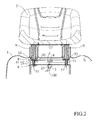
- the cam 4 and the microswitch 3 are centrally positioned with respect to the guiding pins 51 ( figure 2 ), thereby offsetting the unbalances of the weight of the operator to the right or left (operator not seated correctly).
- the present invention also allows protecting the safety device from dust and tractor operation residues. The duration and efficiency of the device is improved.
Abstract
Description
- The present invention concerns a safety device based on the presence of the operator on the seat of a tractor, in particular a tractor mower,
- The presence device of the operator on the seat is the most important unit on the tractor in terms of safety.
- From applicable regulations, it is known that the absence of the operator triggers the blockage of a number of utilities such as the motor; e.g., if the operator abandons the tractor seat, the safety regulations require the motor to be automatically switched off and consequently the tractor and the cutting blades come to a halt within the envisaged space-time limits.
- Safety devices are known with switches located underneath the seat, that require adjustments, or switches inside the seat, both easily accessible for the operator, including the power leads that can be so easily tampered with.
- The above solutions for the conception and the positioning of the switch do not ensure correct operation in certain gradient or rough terrain conditions; even small jumps of the operator positioned on the seat cause continual stops and starts of the tractor due to the continual operation of the switch.
- Object of the present invention is therefore to make a protected safety device for tractor mowers that does not require adjustments and ensures operation in all work conditions, with component parts that are simple to make.
- According to the invention, such object is achieved with a safety device based on the presence of the operator on a seat, particularly for tractor mower, comprising a switch for re-establishing the safety conditions in case of the absence of the operator from the seat, and means for operating the switch in association with the presence or not of the operator on the seat, characterised in that it envisages a fixed inferior switch support integral with the tractor frame, a moving superior support of a switch operating means vertically sliding along guiding pins and associated with the lowering of the seat in the presence of the operator by means of shock absorbers integral with said mobile support, springs interposed between the fixed support and the mobile support and slidably embracing the vertical guiding pins, said fixed support and mobile support being in reversible reciprocal insertion between them in case of the presence of the operator on the seat, the switch, the operating means and the springs being enclosed between the fixed support and the mobile support.
- These and other characteristics of the present invention will be made clearer by the following detailed description of an example of its practical embodiment illustrated by, but not limited to the attached drawings, in which:
- the
figure 1 shows a vertical section view of a seat of a tractor without operator, or with the switch deactivated; - the
figure 2 shows a section view of thefigure 1 according to the line II-II; - the
figure 3 shows a partial view of thefigure 2 with operator, or with switch activated. - With reference to the
figure 1 , a safety device 1 can be seen based on the presence of an operator on aseat 2, particularly for tractor mower, not shown, comprising a microswitch or switch 3 for re-establishing the safety conditions in case of the absence of the operator from theseat 2, and operatingmeans 4, 11 of themicroswitch 3 in relation to the presence or not of the operator on theseat 2. Themicroswitch 3 and said operating means 4, 11 of themicroswitch 3 are enclosed by means ofprotection microswitch 3 with relevant power leads orwiring harness 100 making them inaccessible to the operator and preventing tampering and accidental damage. - In the
figures 2 and3 in particular the operating means can be seen of themicroswitch 3 which are a cam 4 and a pair ofsprings 11 which embrace slidably by means of cylindrical slidingspacers 50 respective vertical guidingpins 51 fastened to theframe 7 of the tractor. - The
seat 2 is mounted on aplate 17 integral with this, connected in a turning way in the anterior part by means of afulcrum 19 and abracket 18, integral with theframe 7 of the tractor. - The posterior part of the
seat 2 rests on thesuperior extremity 14 of two shock-absorbingsprings 9, or analogous drive means 9 not considered here, while theinferior extremity 15 of said shock-absorbingsprings 9 is integral with amobile support 8. - The
mobile support 8 is guided vertically by thepins 51 which at the superior extremity havesuperior stop elements 52, themobile support 8 being pushed upwards by thesprings 11. In the absence of the operator on the seat, thesuperior support 8 is stopped up against thesuperior stop elements 52. - The
mobile support 8 fits in a reversible way above afixed support 6 rigidly connected to theframe 7. The guidingpins 51 are in the inferior part integral with thefixed support 6 which represents the inferior stop element of themobile support 8. Thesprings 11 are then interposed between thefixed support 6 and themobile support 8. - When the operator is on the seat, the
mobile support 8 fits completely reversibly on thefixed support 6 compressing thesprings 11 until the inferior stop is reached. Thesprings 11 are in any case designed to ensure the stop of themobile support 8 and therefore the total operation of thelever 23 of theswitch 3, because this also facilitates correct operation on rough and sloped terrain. If thesprings 11 are only partially compressed, thelever 23 would be only partially operated and in case of uneven terrain, the elastic play would cause the deactivating and reactivating of theswitch 3 prejudicing the continuous movement of the tractor. - Advantageously, the
springs 11 are positioned and sized to suit the shape and weight of the seat in such a way that if a limited weight is accidentally present on the seat, e.g., a tool weighing a few kilos, the safety conditions are maintained as envisaged in the absence of the operator. - To the
mobile support 8, and in a position suitable to operate themicroswitch 3, the cam 4 is connected, which in the presence of the operator operates thelever 23 of themicroswitch 3. - When the operator is absent, the
springs 11 move themobile support 8 vertically away from thefixed support 6, lifting the cam 4 from thelever 23 of themicroswitch 3, determining a safety situation envisaged in the absence of the operator. - As is clear from the
figure 3 , the cam 4 has an inferior surface with central concavity, such as to prevent thelever 23 from sticking. - In particular, the weight of the operator acts not only on the
bracket 18 which discharges on theframe 7, but also on the shock-absorbingsprings 9, connected to themobile support 8 on which they discharge their part of weight. Themobile support 8 with connected cam 4 drops because the constant elasticity of thesprings 11 is below that of the shock-absorbingsprings 9 operating themicroswitch 3. - Advantageously, the
fixed support 6 and themobile support 8 comprise reciprocalguide side surfaces 13 suitable for favouring a reciprocal centred insertion, and a protection of the operating means 4, 11. More specifically, themobile support 8 is "C" shaped with aperture towards the bottom of such width as to contain the analogous "C" shape with aperture towards the top but with a reduced width of thefixed support 6, the coupling achieving a closed protective section hollow shape (figure 1 ). - Advantageously, the means of protection of the operator presence device comprise a wheel-covering
body 5 integral with theframe 7 that covers thefixed support 6 and themobile support 8, making thesupports - The
body 5 comprises two holes for the passage of theshock absorbers 9 which remain prevalently external though protected byhoods 22. - The difficulties are therefore ensured of accessing the safety device and the relevant power leads, in any case reachable by removing the posterior plate of the tractor in case of need.
- The cam 4 and the
microswitch 3 are centrally positioned with respect to the guiding pins 51 (figure 2 ), thereby offsetting the unbalances of the weight of the operator to the right or left (operator not seated correctly). - The present invention also allows protecting the safety device from dust and tractor operation residues. The duration and efficiency of the device is improved.
Claims (5)
- Safety device (1) based on the presence of the operator on the seat (2), particularly for a tractor mower, comprising a switch (3) for the reestablishment of the safety conditions in case of absence of the operator on the seat (2), and operating means (4) of the switch (3) in association with the presence or not of the operator on the seat (2),
characterized in that it provides
a fixed inferior support (6) of the switch (3) integral with the frame (7) of the tractor,
a mobile superior support (8) of operating means (4) of the switch (3) vertically slidable along guiding pins (51) and associated to the lowering of the seat (2) in presence of the operator by means of shock absorbers (9) integral to said mobile support (8),
springs (11) interposed between the fixed support (6) and the mobile support (8) and slidably embracing the vertical guiding pins (51),
said fixed support (6) and mobile support (8) being in relation of reversibile reciprocal insertion between them in case of presence of the operator on the seat (2), the switch (3), operating means (4) and the springs (11) being enclosed between the fixed support (6) and the mobile support (8). - Device (1) according to claim 1, characterized in that the mobile support (8) has a "C" shape with aperture towards the bottom of such width as to contain and contribute to guide the analogous "C" shape with aperture towards the top but with a reduced width of the fixed support (6), the coupling achieving a closed protective section hollow shape.
- Device (1) according to any of the preceding claims, characterized in that the mobile support (8) is vertically slidable between a raised position without seated operator and deactivated switch wherein it interacts with superior stops (52) of the guiding pins (51), and a lowered position with seated operator and activated switch wherein it rests on the fixed support (6) with compressed springs (11).
- Device (1) according to any of the preceding claims, characterized in that the fixed support (6) and the mobile support (8) are contained together with the wiring harness (100) inside a body (5).
- Device (1) according to any of the preceding claims, characterized in that wiring harness (100) is accessible only removing a posterior plate or the body (5).
Applications Claiming Priority (1)
| Application Number | Priority Date | Filing Date | Title |
|---|---|---|---|
| ITMI2008A002159A IT1392080B1 (en) | 2008-12-05 | 2008-12-05 | SAFETY DEVICE CONNECTED TO THE PRESENCE OF THE OPERATOR ON THE SEAT OF A TRACTOR |
Publications (2)
| Publication Number | Publication Date |
|---|---|
| EP2193703A1 true EP2193703A1 (en) | 2010-06-09 |
| EP2193703B1 EP2193703B1 (en) | 2016-11-02 |
Family
ID=40852127
Family Applications (1)
| Application Number | Title | Priority Date | Filing Date |
|---|---|---|---|
| EP09177766.4A Active EP2193703B1 (en) | 2008-12-05 | 2009-12-02 | Safety device based on a presence of the operator on the seat of a tractor |
Country Status (2)
| Country | Link |
|---|---|
| EP (1) | EP2193703B1 (en) |
| IT (1) | IT1392080B1 (en) |
Cited By (3)
| Publication number | Priority date | Publication date | Assignee | Title |
|---|---|---|---|---|
| EP2929772A1 (en) * | 2014-04-09 | 2015-10-14 | GGP Italy S.p.A. | Riding mower with control tamper apparatus |
| CN109892113A (en) * | 2019-02-01 | 2019-06-18 | 江苏朗鸿机电有限公司 | A kind of easy cleaning and easy-to-mount mowing machine baffle |
| US10858051B2 (en) | 2018-07-03 | 2020-12-08 | Mtd Products Inc | Standing platform and suspension assembly for riding equipment |
Citations (6)
| Publication number | Priority date | Publication date | Assignee | Title |
|---|---|---|---|---|
| US2794089A (en) * | 1954-12-20 | 1957-05-28 | James N Hogg | Switches for automotive vehicles |
| US4385863A (en) * | 1981-05-13 | 1983-05-31 | Sperry Corporation | Seat interlock for skid-steer loader |
| EP0518162A2 (en) * | 1991-06-14 | 1992-12-16 | Deere & Company | Safety switch arrangement for a vehicle |
| CA1336105C (en) * | 1988-07-29 | 1995-06-27 | David Roy Holm | Tractor operator presence indicator switch mounting |
| US20040090338A1 (en) * | 2002-11-11 | 2004-05-13 | Kubota Corporation | Operator presence sensing apparatus for a seat of a vehicle |
| WO2007145723A2 (en) * | 2006-06-08 | 2007-12-21 | Illinois Tool Works Inc. | Safety switch assembly |
-
2008
- 2008-12-05 IT ITMI2008A002159A patent/IT1392080B1/en active
-
2009
- 2009-12-02 EP EP09177766.4A patent/EP2193703B1/en active Active
Patent Citations (6)
| Publication number | Priority date | Publication date | Assignee | Title |
|---|---|---|---|---|
| US2794089A (en) * | 1954-12-20 | 1957-05-28 | James N Hogg | Switches for automotive vehicles |
| US4385863A (en) * | 1981-05-13 | 1983-05-31 | Sperry Corporation | Seat interlock for skid-steer loader |
| CA1336105C (en) * | 1988-07-29 | 1995-06-27 | David Roy Holm | Tractor operator presence indicator switch mounting |
| EP0518162A2 (en) * | 1991-06-14 | 1992-12-16 | Deere & Company | Safety switch arrangement for a vehicle |
| US20040090338A1 (en) * | 2002-11-11 | 2004-05-13 | Kubota Corporation | Operator presence sensing apparatus for a seat of a vehicle |
| WO2007145723A2 (en) * | 2006-06-08 | 2007-12-21 | Illinois Tool Works Inc. | Safety switch assembly |
Cited By (3)
| Publication number | Priority date | Publication date | Assignee | Title |
|---|---|---|---|---|
| EP2929772A1 (en) * | 2014-04-09 | 2015-10-14 | GGP Italy S.p.A. | Riding mower with control tamper apparatus |
| US10858051B2 (en) | 2018-07-03 | 2020-12-08 | Mtd Products Inc | Standing platform and suspension assembly for riding equipment |
| CN109892113A (en) * | 2019-02-01 | 2019-06-18 | 江苏朗鸿机电有限公司 | A kind of easy cleaning and easy-to-mount mowing machine baffle |
Also Published As
| Publication number | Publication date |
|---|---|
| IT1392080B1 (en) | 2012-02-09 |
| EP2193703B1 (en) | 2016-11-02 |
| ITMI20082159A1 (en) | 2010-06-06 |
Similar Documents
| Publication | Publication Date | Title |
|---|---|---|
| EP2193703B1 (en) | Safety device based on a presence of the operator on the seat of a tractor | |
| EP2077067B1 (en) | Single lever mower deck height-of-cut control | |
| AU2016365783B2 (en) | Control station for work platform of an aerial lift | |
| CN109952266B (en) | Safety device of movable operation platform | |
| CN104135846A (en) | Robotic lawnmower | |
| KR20080053882A (en) | Pothole protection mechanism | |
| WO2015004178A1 (en) | Aerial lift platform and aerial lift including such a platform | |
| EP2340699A1 (en) | Linkage attachment means for a vehicle | |
| JP2018061496A (en) | Grass mower | |
| JP6368704B2 (en) | Load detection system for wheelchair lift device | |
| US6317914B1 (en) | Dockleveler holdown mechanism and method for installing the same | |
| KR100797930B1 (en) | A car lift having safe sensor | |
| JP6856920B2 (en) | Mower | |
| KR101581881B1 (en) | Automatically Monitor Receiving Type Desk | |
| JP5379030B2 (en) | Chain saw | |
| KR101105261B1 (en) | Spin protecting device of plate for bush cutting machine | |
| EP3323281B1 (en) | Damping device for farm implements | |
| KR102021991B1 (en) | The removal apparatus of the feces for the cattle shed | |
| EP3878796B1 (en) | A lifting device for maintenance and repair of motorized two-wheeled vehicles | |
| JP6925217B2 (en) | Riding mower | |
| KR20160090718A (en) | Lawn trimmer of large area of traction type | |
| JP6618795B2 (en) | rack | |
| JP6822882B2 (en) | Height adjuster for brush cutter | |
| WO2007107676B1 (en) | Product-spreading agricultural apparatus equipped with an anti-impact device | |
| JP6864283B2 (en) | Crop harvester |
Legal Events
| Date | Code | Title | Description |
|---|---|---|---|
| PUAI | Public reference made under article 153(3) epc to a published international application that has entered the european phase |
Free format text: ORIGINAL CODE: 0009012 |
|
| AK | Designated contracting states |
Kind code of ref document: A1 Designated state(s): AT BE BG CH CY CZ DE DK EE ES FI FR GB GR HR HU IE IS IT LI LT LU LV MC MK MT NL NO PL PT RO SE SI SK SM TR |
|
| 17P | Request for examination filed |
Effective date: 20101115 |
|
| 17Q | First examination report despatched |
Effective date: 20110113 |
|
| GRAP | Despatch of communication of intention to grant a patent |
Free format text: ORIGINAL CODE: EPIDOSNIGR1 |
|
| INTG | Intention to grant announced |
Effective date: 20160603 |
|
| RIC1 | Information provided on ipc code assigned before grant |
Ipc: A01D 75/20 20060101ALI20160523BHEP Ipc: A01D 34/82 20060101AFI20160523BHEP Ipc: A01D 67/04 20060101ALI20160523BHEP Ipc: A01D 75/18 20060101ALI20160523BHEP Ipc: B60K 28/04 20060101ALI20160523BHEP Ipc: B60N 2/00 20060101ALI20160523BHEP |
|
| GRAS | Grant fee paid |
Free format text: ORIGINAL CODE: EPIDOSNIGR3 |
|
| GRAA | (expected) grant |
Free format text: ORIGINAL CODE: 0009210 |
|
| AK | Designated contracting states |
Kind code of ref document: B1 Designated state(s): AT BE BG CH CY CZ DE DK EE ES FI FR GB GR HR HU IE IS IT LI LT LU LV MC MK MT NL NO PL PT RO SE SI SK SM TR |
|
| REG | Reference to a national code |
Ref country code: GB Ref legal event code: FG4D |
|
| REG | Reference to a national code |
Ref country code: AT Ref legal event code: REF Ref document number: 840822 Country of ref document: AT Kind code of ref document: T Effective date: 20161115 Ref country code: CH Ref legal event code: EP |
|
| REG | Reference to a national code |
Ref country code: IE Ref legal event code: FG4D |
|
| REG | Reference to a national code |
Ref country code: DE Ref legal event code: R096 Ref document number: 602009042052 Country of ref document: DE |
|
| REG | Reference to a national code |
Ref country code: FR Ref legal event code: PLFP Year of fee payment: 8 |
|
| PG25 | Lapsed in a contracting state [announced via postgrant information from national office to epo] |
Ref country code: LV Free format text: LAPSE BECAUSE OF FAILURE TO SUBMIT A TRANSLATION OF THE DESCRIPTION OR TO PAY THE FEE WITHIN THE PRESCRIBED TIME-LIMIT Effective date: 20161102 |
|
| REG | Reference to a national code |
Ref country code: NL Ref legal event code: MP Effective date: 20161102 |
|
| REG | Reference to a national code |
Ref country code: LT Ref legal event code: MG4D |
|
| REG | Reference to a national code |
Ref country code: AT Ref legal event code: MK05 Ref document number: 840822 Country of ref document: AT Kind code of ref document: T Effective date: 20161102 |
|
| PG25 | Lapsed in a contracting state [announced via postgrant information from national office to epo] |
Ref country code: GR Free format text: LAPSE BECAUSE OF FAILURE TO SUBMIT A TRANSLATION OF THE DESCRIPTION OR TO PAY THE FEE WITHIN THE PRESCRIBED TIME-LIMIT Effective date: 20170203 Ref country code: NL Free format text: LAPSE BECAUSE OF FAILURE TO SUBMIT A TRANSLATION OF THE DESCRIPTION OR TO PAY THE FEE WITHIN THE PRESCRIBED TIME-LIMIT Effective date: 20161102 Ref country code: NO Free format text: LAPSE BECAUSE OF FAILURE TO SUBMIT A TRANSLATION OF THE DESCRIPTION OR TO PAY THE FEE WITHIN THE PRESCRIBED TIME-LIMIT Effective date: 20170202 Ref country code: SE Free format text: LAPSE BECAUSE OF FAILURE TO SUBMIT A TRANSLATION OF THE DESCRIPTION OR TO PAY THE FEE WITHIN THE PRESCRIBED TIME-LIMIT Effective date: 20161102 Ref country code: LT Free format text: LAPSE BECAUSE OF FAILURE TO SUBMIT A TRANSLATION OF THE DESCRIPTION OR TO PAY THE FEE WITHIN THE PRESCRIBED TIME-LIMIT Effective date: 20161102 |
|
| PG25 | Lapsed in a contracting state [announced via postgrant information from national office to epo] |
Ref country code: BE Free format text: LAPSE BECAUSE OF NON-PAYMENT OF DUE FEES Effective date: 20161231 Ref country code: PL Free format text: LAPSE BECAUSE OF FAILURE TO SUBMIT A TRANSLATION OF THE DESCRIPTION OR TO PAY THE FEE WITHIN THE PRESCRIBED TIME-LIMIT Effective date: 20161102 Ref country code: FI Free format text: LAPSE BECAUSE OF FAILURE TO SUBMIT A TRANSLATION OF THE DESCRIPTION OR TO PAY THE FEE WITHIN THE PRESCRIBED TIME-LIMIT Effective date: 20161102 Ref country code: PT Free format text: LAPSE BECAUSE OF FAILURE TO SUBMIT A TRANSLATION OF THE DESCRIPTION OR TO PAY THE FEE WITHIN THE PRESCRIBED TIME-LIMIT Effective date: 20170302 Ref country code: IS Free format text: LAPSE BECAUSE OF FAILURE TO SUBMIT A TRANSLATION OF THE DESCRIPTION OR TO PAY THE FEE WITHIN THE PRESCRIBED TIME-LIMIT Effective date: 20170302 Ref country code: HR Free format text: LAPSE BECAUSE OF FAILURE TO SUBMIT A TRANSLATION OF THE DESCRIPTION OR TO PAY THE FEE WITHIN THE PRESCRIBED TIME-LIMIT Effective date: 20161102 Ref country code: ES Free format text: LAPSE BECAUSE OF FAILURE TO SUBMIT A TRANSLATION OF THE DESCRIPTION OR TO PAY THE FEE WITHIN THE PRESCRIBED TIME-LIMIT Effective date: 20161102 Ref country code: AT Free format text: LAPSE BECAUSE OF FAILURE TO SUBMIT A TRANSLATION OF THE DESCRIPTION OR TO PAY THE FEE WITHIN THE PRESCRIBED TIME-LIMIT Effective date: 20161102 |
|
| PG25 | Lapsed in a contracting state [announced via postgrant information from national office to epo] |
Ref country code: EE Free format text: LAPSE BECAUSE OF FAILURE TO SUBMIT A TRANSLATION OF THE DESCRIPTION OR TO PAY THE FEE WITHIN THE PRESCRIBED TIME-LIMIT Effective date: 20161102 Ref country code: RO Free format text: LAPSE BECAUSE OF FAILURE TO SUBMIT A TRANSLATION OF THE DESCRIPTION OR TO PAY THE FEE WITHIN THE PRESCRIBED TIME-LIMIT Effective date: 20161102 Ref country code: CZ Free format text: LAPSE BECAUSE OF FAILURE TO SUBMIT A TRANSLATION OF THE DESCRIPTION OR TO PAY THE FEE WITHIN THE PRESCRIBED TIME-LIMIT Effective date: 20161102 Ref country code: SK Free format text: LAPSE BECAUSE OF FAILURE TO SUBMIT A TRANSLATION OF THE DESCRIPTION OR TO PAY THE FEE WITHIN THE PRESCRIBED TIME-LIMIT Effective date: 20161102 Ref country code: DK Free format text: LAPSE BECAUSE OF FAILURE TO SUBMIT A TRANSLATION OF THE DESCRIPTION OR TO PAY THE FEE WITHIN THE PRESCRIBED TIME-LIMIT Effective date: 20161102 |
|
| REG | Reference to a national code |
Ref country code: CH Ref legal event code: PL |
|
| REG | Reference to a national code |
Ref country code: DE Ref legal event code: R097 Ref document number: 602009042052 Country of ref document: DE |
|
| PG25 | Lapsed in a contracting state [announced via postgrant information from national office to epo] |
Ref country code: SM Free format text: LAPSE BECAUSE OF FAILURE TO SUBMIT A TRANSLATION OF THE DESCRIPTION OR TO PAY THE FEE WITHIN THE PRESCRIBED TIME-LIMIT Effective date: 20161102 Ref country code: BE Free format text: LAPSE BECAUSE OF FAILURE TO SUBMIT A TRANSLATION OF THE DESCRIPTION OR TO PAY THE FEE WITHIN THE PRESCRIBED TIME-LIMIT Effective date: 20161102 Ref country code: BG Free format text: LAPSE BECAUSE OF FAILURE TO SUBMIT A TRANSLATION OF THE DESCRIPTION OR TO PAY THE FEE WITHIN THE PRESCRIBED TIME-LIMIT Effective date: 20170202 |
|
| PLBE | No opposition filed within time limit |
Free format text: ORIGINAL CODE: 0009261 |
|
| STAA | Information on the status of an ep patent application or granted ep patent |
Free format text: STATUS: NO OPPOSITION FILED WITHIN TIME LIMIT |
|
| PG25 | Lapsed in a contracting state [announced via postgrant information from national office to epo] |
Ref country code: MC Free format text: LAPSE BECAUSE OF FAILURE TO SUBMIT A TRANSLATION OF THE DESCRIPTION OR TO PAY THE FEE WITHIN THE PRESCRIBED TIME-LIMIT Effective date: 20161102 |
|
| REG | Reference to a national code |
Ref country code: IE Ref legal event code: MM4A |
|
| 26N | No opposition filed |
Effective date: 20170803 |
|
| PG25 | Lapsed in a contracting state [announced via postgrant information from national office to epo] |
Ref country code: LU Free format text: LAPSE BECAUSE OF NON-PAYMENT OF DUE FEES Effective date: 20161202 Ref country code: LI Free format text: LAPSE BECAUSE OF NON-PAYMENT OF DUE FEES Effective date: 20161231 Ref country code: CH Free format text: LAPSE BECAUSE OF NON-PAYMENT OF DUE FEES Effective date: 20161231 |
|
| REG | Reference to a national code |
Ref country code: FR Ref legal event code: PLFP Year of fee payment: 9 |
|
| PG25 | Lapsed in a contracting state [announced via postgrant information from national office to epo] |
Ref country code: IE Free format text: LAPSE BECAUSE OF NON-PAYMENT OF DUE FEES Effective date: 20161202 Ref country code: SI Free format text: LAPSE BECAUSE OF FAILURE TO SUBMIT A TRANSLATION OF THE DESCRIPTION OR TO PAY THE FEE WITHIN THE PRESCRIBED TIME-LIMIT Effective date: 20161102 |
|
| PG25 | Lapsed in a contracting state [announced via postgrant information from national office to epo] |
Ref country code: CY Free format text: LAPSE BECAUSE OF FAILURE TO SUBMIT A TRANSLATION OF THE DESCRIPTION OR TO PAY THE FEE WITHIN THE PRESCRIBED TIME-LIMIT Effective date: 20161102 Ref country code: HU Free format text: LAPSE BECAUSE OF FAILURE TO SUBMIT A TRANSLATION OF THE DESCRIPTION OR TO PAY THE FEE WITHIN THE PRESCRIBED TIME-LIMIT; INVALID AB INITIO Effective date: 20091202 |
|
| PG25 | Lapsed in a contracting state [announced via postgrant information from national office to epo] |
Ref country code: TR Free format text: LAPSE BECAUSE OF FAILURE TO SUBMIT A TRANSLATION OF THE DESCRIPTION OR TO PAY THE FEE WITHIN THE PRESCRIBED TIME-LIMIT Effective date: 20161102 Ref country code: MK Free format text: LAPSE BECAUSE OF FAILURE TO SUBMIT A TRANSLATION OF THE DESCRIPTION OR TO PAY THE FEE WITHIN THE PRESCRIBED TIME-LIMIT Effective date: 20161102 |
|
| PG25 | Lapsed in a contracting state [announced via postgrant information from national office to epo] |
Ref country code: MT Free format text: LAPSE BECAUSE OF NON-PAYMENT OF DUE FEES Effective date: 20161202 |
|
| PGFP | Annual fee paid to national office [announced via postgrant information from national office to epo] |
Ref country code: DE Payment date: 20221227 Year of fee payment: 14 |
|
| P01 | Opt-out of the competence of the unified patent court (upc) registered |
Effective date: 20230421 |
|
| REG | Reference to a national code |
Ref country code: DE Ref legal event code: R082 Ref document number: 602009042052 Country of ref document: DE Representative=s name: UEXKUELL & STOLBERG PARTNERSCHAFT VON PATENT- , DE |
|
| REG | Reference to a national code |
Ref country code: DE Ref legal event code: R039 Ref document number: 602009042052 Country of ref document: DE Ref country code: DE Ref legal event code: R008 Ref document number: 602009042052 Country of ref document: DE |
|
| PGFP | Annual fee paid to national office [announced via postgrant information from national office to epo] |
Ref country code: GB Payment date: 20231219 Year of fee payment: 15 |
|
| PGFP | Annual fee paid to national office [announced via postgrant information from national office to epo] |
Ref country code: IT Payment date: 20231214 Year of fee payment: 15 Ref country code: FR Payment date: 20231220 Year of fee payment: 15 |