EP2193240B1 - Small loader having adjustable hand controls, and adjustable hand controls for such a loader - Google Patents
Small loader having adjustable hand controls, and adjustable hand controls for such a loader Download PDFInfo
- Publication number
- EP2193240B1 EP2193240B1 EP08833844A EP08833844A EP2193240B1 EP 2193240 B1 EP2193240 B1 EP 2193240B1 EP 08833844 A EP08833844 A EP 08833844A EP 08833844 A EP08833844 A EP 08833844A EP 2193240 B1 EP2193240 B1 EP 2193240B1
- Authority
- EP
- European Patent Office
- Prior art keywords
- control
- vehicle
- axis
- control handle
- support plate
- Prior art date
- Legal status (The legal status is an assumption and is not a legal conclusion. Google has not performed a legal analysis and makes no representation as to the accuracy of the status listed.)
- Not-in-force
Links
- 230000008878 coupling Effects 0.000 abstract description 4
- 238000010168 coupling process Methods 0.000 abstract description 4
- 238000005859 coupling reaction Methods 0.000 abstract description 4
- 210000005069 ears Anatomy 0.000 description 2
- 238000002485 combustion reaction Methods 0.000 description 1
- 238000010276 construction Methods 0.000 description 1
- 230000000284 resting effect Effects 0.000 description 1
Images


Classifications
-
- E—FIXED CONSTRUCTIONS
- E02—HYDRAULIC ENGINEERING; FOUNDATIONS; SOIL SHIFTING
- E02F—DREDGING; SOIL-SHIFTING
- E02F9/00—Component parts of dredgers or soil-shifting machines, not restricted to one of the kinds covered by groups E02F3/00 - E02F7/00
- E02F9/20—Drives; Control devices
- E02F9/2004—Control mechanisms, e.g. control levers
Definitions
- the present invention relates to hand controls for controlling the steering direction and speed of movement of a loader.
- the invention provides a control system for a skid steer loader, as disclosed in US Patent No. 7,059,434 , including a control handle pivotally coupled to a vertical link about a first horizontal axis and pivotally coupled to a shaft about a vertical axis, wherein pivoting the control handle about the horizontal axis provides a forward/reverse direction and speed control input and pivoting the control handle about the vertical axis provides a steering control input.
- the control handle being pivotally coupled to a control handle support platform about a second horizontal axis parallel to the first horizontal axis, as defined in the characteristic part of claim 1 and in the characteristic part of claim 8.
- the control handle being movable relative the control handle support platform about the second horizontal axis between a first position and a second position that change the elevations of the control handle.
- FIGS. 1 and 2 show a small skid steer loader 10.
- the loader has a frame 12 that supports upright side plates 14 on opposite sides of the loader 10.
- the plates 14 are part of the frame 12 and are joined with cross plates as needed (not shown).
- the rear portions of the loader 10 have rear side plates 20 that are spaced from and parallel to the frame plates 14.
- the spaces between the rear side plates 20 and the frame plates 14 are used for mounting a lift arm assembly 24.
- the lift arm assembly 24 includes individual lift arms 25 pivotally mounted as at 26 to the frame 12 and positioned in a desired location.
- Lift actuators or cylinders (not shown) are provided for pivoting the lift arms 25 about pivot 26 to raise and lower forward ends of the lift arms 25.
- a bucket control or tilt cylinder 27 is mounted to the lift arms 25 for controlling movement of a loader bucket 28, or for other accessories that may be mounted on an attachment plate 29 at the front end of the lift arms 25.
- the loader 10 has an internal combustion engine, shown in dashed lines at 30, that is used for driving a hydraulic pump for the lift actuators and the tilt cylinder 27. Also, the engine 30 drives pump and motor units for a ground drive system 32 including a motor (not shown) and motor controls 34, which drive system can be electric or other type of controlled drive.
- a motor not shown
- motor controls 34 which drive system can be electric or other type of controlled drive.
- the ground drive system 32 includes drive tracks 36 mounted on the sides of the loader 10.
- the tracks 36 mount over suitable idler rollers 38. Wheeled loaders or vehicles would be driven with normal mechanical drive trains to the wheels, or can be operated with ground engaging wheels mounted right on motor shafts.
- the loader 10 further includes a ride-on platform 40 as illustrated in FIG. 2 .
- the ride-on platform 40 is mounted to a rear of the loader 10 to support the operator for movement over the ground or supporting surface.
- the operator, supported on the ride-on platform 40 can operate the loader 10 via the control system 34.
- the ride-on platform 40 can be detached and/or moved out of the way, as shown in FIG. 1 , so that the operator can walk over the ground or supporting surface behind the loader 10 to direct operation of the loader 10 via the control system 34 at a different support level than when the ride-on platform is used.
- the control system 34 is a drive and steering control assembly using a single control handle, so that an operator can steer and control speed and direction of movement of the loader 10 with one hand, if desired, in a convenient manner.
- Control system 34 can have a configuration as is shown and described in U.S. Patent No. 7.059.434 .
- the control system 34 is shown in more detail in FIGS. 3-5 . It should be noted that a lever (not shown) can be provided for controlling the cylinders for the lift arm 25, and the valves for controlling other cylinders, such as the tilt cylinder 27, can be controlled as desired. A throttle 58 is provided for controlling the engine speed of engine 30.
- the control system 34 forms an assembly supported relative to a control panel 70 which is fixed to side plates 14.
- the controls 34 include a swinging or movable control handle support plate or platform 72.
- a vertical shaft 78 has a lower end supported on the frame.
- the shaft 78 extends upwardly and can be rotatably supported at the upper end of the suitable manner, relative to the side plate 14 or with a bracket to panel 80, which is fixed to the side plates.
- the shaft 78 is positioned at a desired location to position and mount the control support plate 72 in its proper location.
- the shaft 78 does not move relative to the frame except to rotate, and does not have to be vertical. It can incline somewhat for convenience.
- the shaft 78 forms a main mounting support for the control assembly 34 and a sleeve or hub 80 is rotatably mounted on the shaft 78.
- the sleeve 80 is located in position axially along the shaft 78 with bearings held in place in a suitable manner.
- the sleeve 80 is free to rotate about an axis 82 of the shaft 78.
- a hub 84 at the upper end of sleeve 80 has threaded bores receiving capscrews 81 for holding a support block 86 on stand offs shown that mounts the support plate 72, using suitable fasteners.
- the control handle support plate 72 is securely fixed relative to the sleeve 80, so it will rotate about the axis 82 with the sleeve.
- the control handle support plate 72 extends rearwardly from axis 82 and has a pair of rearwardly extending spaced side arms 73 that are bent down from the center plate and that pivotally mount a pivoting or tilting control handle mounting section 88 forming part of a drive control assembly between the arms 73 and at the rear portions of the arms 73 on pivots 120.
- the control handle mounting section 88 has a top plate 89, and channel-shaped side members, each formed with an inner downwardly depending wall 91, a horizontal bottom wall 93 and an upright spaced apart side arm 90 fixed to the horizontal bottom wall 93.
- the side arms 90 extend above the top plate 89 and a fixed four-sided reference bar or hand rest 92 is mounted on the upper ends of the side arms 90.
- the hand rest 92 defines a center space and surrounds a movable control handle 94 located in the center space.
- the control handle 94 is pivotally mounted on pivots 96 to the depending walls 91 of tilting handle mounting section 88, which is pivotally mounted on side arms 73 of the control handle support plate 72.
- the pivots 96 are at the rear of the pivots for pivoting handle mounting section 88 of the control handle support plate 72 and behind or to the rear of axis 80.
- the handle 94 will pivot relative to the handle mounting section 88 about a generally horizontal axis of pivots 96, which is transverse to and preferably perpendicular to axis 82.
- Handle 94, the handle mounting section 88 and control handle support plate 72 also can be moved as a unit about the axis 82 of upright shaft 78 from side to side, to cause the sleeve 80 to rotate as well.
- the sleeve 80 has a pair of ears 100 that extend laterally from the sleeve 80 near the lower end.
- a pivoting channel shaped bracket 102 is mounted on the ears 100 with suitable pivot pins 104 so that channel bracket 102 will pivot about a generally horizontal axis of the pivot pins 104, that is parallel to the pivotal axis of the control handle at pivot shaft 96.
- the channel shaped bracket 102 extends downwardly from the pivot pins 104 and is coupled to the drive system 32.
- Movement of the bracket 102 about the pivot pins 104 is controlled by the control handle 94 pivoting about the pivot shaft 96.
- the control handle 94 has a forwardly extending arm or lever 110 that is moved by the handle 94 as the handle pivots as well.
- a first end of a link 112 is coupled to the control handle 94 by the forwardly extending arm and has a second end coupled to the bracket 102.
- a drive control assembly 118 including the handle mounting section 88, control handle 94 and the hand rest 92, are pivotally coupled to the side arms 73 of control handle support plate 72 at pivots 120.
- the drive control assembly 118 includes additional features, such as speed limiters.
- the drive control assembly 118 is movable relative to the control support plate 72 about pivots 120 from a first or lowered position to a second or raised position.
- FIG. 4 shows the drive control assembly 118 in the lowered position
- FIG. 5 shows the drive control assembly 118 in the raised position.
- a fastener such as a bolt 124 can be provided for adjustably positioning and retaining the drive control assembly 118 about the pivot 120.
- the fastener can be hand knob or other suitable fasteners such that tools such as screwdrivers are not needed to loosen the fastener and re-position the pivoting drive control assembly 118.
- a slot in the side arms 90 of the control handle mounting section 88 is provided for guiding the drive control assembly 118 between the raised and lowered positions.
- the drive control assembly 118 can be secured relative to the control handle support plate 72 anywhere along the provided slot so that the drive control assembly 118 can be positioned at any selected pivotal location between the raised and lowered positions.
- the pivot 120 is co-axial with the connection between the arm 110 on control handle 94 and the link 112. Repositioning the drive control assembly 118 to the raised or lowered position about pivot 120 does not alter the configuration of the control handle 94 relative to the link 112. Therefore, it is not necessary to adjust the link 112 after repositioning the drive control assembly to maintain an equivalent control over the direction and speed control inputs of the drive system 32 of the loader 10. Thus, the loader 10 will have equivalent speed corresponding to pivoting of the control handle 94 regardless of the pivoted position (up or down) of the drive control assembly 118.
- the loader 10 can be controlled by the operator with the drive control assembly 118 and control handle 94 in.either the raised or lowered position. If the loader 10 is being operated in a walk-behind mode, in which the ride-on platform 40 is detached or moved out of the way so that the operator walks behind the loader 10 to operate the loader 10, as shown in FIG. 1 , the drive control assembly and control handle 94 can be in the lowered position. Conversely, if the loader 10 is being operated in a ride-on mode so that the operator is supported on the ride-on platform 40 behind the loader 10, as shown in FIG. 2 , the drive control assembly 118 and the control handle 94 can be moved upwards into the raised position.
- the drive control assembly 118 and the control handle 94 can be moved into the lowered or raised position to allow differently sized operators to move the control handle to their preference. For example, a taller operator may prefer the control handle 94 in the raised position while a shorter operator may prefer the control handle 94 in the lowered position.
- the drive control assembly 118 can be moved to a raised or lowered position to provide a more comfortable grasping and resting configuration for the operator. This can reduce operator fatigue and increase productivity by increasing the operator's length of operation.
- the invention provides, among other things, an adjustable hand control for controlling operation of a small loader.
Landscapes
- Engineering & Computer Science (AREA)
- Mining & Mineral Resources (AREA)
- Civil Engineering (AREA)
- General Engineering & Computer Science (AREA)
- Structural Engineering (AREA)
- Operation Control Of Excavators (AREA)
- Harvester Elements (AREA)
- Mechanical Control Devices (AREA)
Abstract
Description
- The present invention relates to hand controls for controlling the steering direction and speed of movement of a loader.
- In one embodiment, the invention provides a control system for a skid steer loader, as disclosed in
US Patent No. 7,059,434 , including a control handle pivotally coupled to a vertical link about a first horizontal axis and pivotally coupled to a shaft about a vertical axis, wherein pivoting the control handle about the horizontal axis provides a forward/reverse direction and speed control input and pivoting the control handle about the vertical axis provides a steering control input. The control handle being pivotally coupled to a control handle support platform about a second horizontal axis parallel to the first horizontal axis, as defined in the characteristic part of claim 1 and in the characteristic part of claim 8. The control handle being movable relative the control handle support platform about the second horizontal axis between a first position and a second position that change the elevations of the control handle. - Other aspects of the invention will become apparent by consideration of the detailed description and accompanying drawings.
-
-
FIG. 1 shows a side view of a small loader without a ride-on platform according to an embodiment of the invention. -
FIG. 2 shows a side view of the small loader ofFIG. 1 with a ride-on platform. -
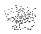
FIG. 3 shows a perspective view of the operator controls of the small loader ofFIG. 1 . -
FIG. 4 shows a side cut-away view of the operator controls ofFIG. 3 in a lowered position. -
FIG. 5 shows a side cut-away view of the operator controls ofFIG. 3 in a raised position. - Before any embodiments of the invention are explained in detail, it is to be understood that the invention is not limited in its application to the details of construction and the arrangement of components set forth in the following description or illustrated in following drawings. The invention is capable of other embodiments without departing from the scope, as defined in the claims . It is to be understood that the phraseology and terminology used herein is for the purpose of description and should not be regarded as limiting. The use of "including," "comprising," or "having" and variations thereof herein is meant to encompass the items listed thereafter and equivalents thereof as well as additional items. Unless specified or limited otherwise, the terms "mounted," "connected," "supported," and "coupled" and variations thereof are used broadly and encompass both direct and indirect mountings, connections, supports, and couplings. Further, "connected" and "coupled" are not restricted to physical or mechanical connections or couplings.
-
FIGS. 1 and 2 show a smallskid steer loader 10. The loader has a frame 12 that supportsupright side plates 14 on opposite sides of theloader 10. Theplates 14 are part of the frame 12 and are joined with cross plates as needed (not shown). - The rear portions of the
loader 10 haverear side plates 20 that are spaced from and parallel to theframe plates 14. The spaces between therear side plates 20 and theframe plates 14 are used for mounting alift arm assembly 24. Thelift arm assembly 24 includesindividual lift arms 25 pivotally mounted as at 26 to the frame 12 and positioned in a desired location. Lift actuators or cylinders (not shown) are provided for pivoting thelift arms 25 aboutpivot 26 to raise and lower forward ends of thelift arms 25. A bucket control ortilt cylinder 27 is mounted to thelift arms 25 for controlling movement of aloader bucket 28, or for other accessories that may be mounted on anattachment plate 29 at the front end of thelift arms 25. - The
loader 10 has an internal combustion engine, shown in dashed lines at 30, that is used for driving a hydraulic pump for the lift actuators and thetilt cylinder 27. Also, theengine 30 drives pump and motor units for aground drive system 32 including a motor (not shown) andmotor controls 34, which drive system can be electric or other type of controlled drive. - The
ground drive system 32 includesdrive tracks 36 mounted on the sides of theloader 10. Thetracks 36 mount oversuitable idler rollers 38. Wheeled loaders or vehicles would be driven with normal mechanical drive trains to the wheels, or can be operated with ground engaging wheels mounted right on motor shafts. - The
loader 10 further includes a ride-onplatform 40 as illustrated inFIG. 2 . The ride-onplatform 40 is mounted to a rear of theloader 10 to support the operator for movement over the ground or supporting surface. The operator, supported on the ride-onplatform 40, can operate theloader 10 via thecontrol system 34. The ride-onplatform 40 can be detached and/or moved out of the way, as shown inFIG. 1 , so that the operator can walk over the ground or supporting surface behind theloader 10 to direct operation of theloader 10 via thecontrol system 34 at a different support level than when the ride-on platform is used. - The
control system 34 is a drive and steering control assembly using a single control handle, so that an operator can steer and control speed and direction of movement of theloader 10 with one hand, if desired, in a convenient manner.Control system 34 can have a configuration as is shown and described inU.S. Patent No. 7.059.434 . - The
control system 34 is shown in more detail inFIGS. 3-5 . It should be noted that a lever (not shown) can be provided for controlling the cylinders for thelift arm 25, and the valves for controlling other cylinders, such as thetilt cylinder 27, can be controlled as desired. A throttle 58 is provided for controlling the engine speed ofengine 30. - The
control system 34 forms an assembly supported relative to acontrol panel 70 which is fixed toside plates 14. Thecontrols 34 include a swinging or movable control handle support plate orplatform 72. As shown inFIG. 5 , for example, avertical shaft 78 has a lower end supported on the frame. Theshaft 78 extends upwardly and can be rotatably supported at the upper end of the suitable manner, relative to theside plate 14 or with a bracket topanel 80, which is fixed to the side plates. Theshaft 78 is positioned at a desired location to position and mount thecontrol support plate 72 in its proper location. Theshaft 78 does not move relative to the frame except to rotate, and does not have to be vertical. It can incline somewhat for convenience. - The
shaft 78 forms a main mounting support for thecontrol assembly 34 and a sleeve orhub 80 is rotatably mounted on theshaft 78. Thesleeve 80 is located in position axially along theshaft 78 with bearings held in place in a suitable manner. Thesleeve 80 is free to rotate about anaxis 82 of theshaft 78. Ahub 84 at the upper end ofsleeve 80 has threadedbores receiving capscrews 81 for holding asupport block 86 on stand offs shown that mounts thesupport plate 72, using suitable fasteners. - The control
handle support plate 72 is securely fixed relative to thesleeve 80, so it will rotate about theaxis 82 with the sleeve. The controlhandle support plate 72 extends rearwardly fromaxis 82 and has a pair of rearwardly extendingspaced side arms 73 that are bent down from the center plate and that pivotally mount a pivoting or tilting controlhandle mounting section 88 forming part of a drive control assembly between thearms 73 and at the rear portions of thearms 73 onpivots 120.. The controlhandle mounting section 88 has atop plate 89, and channel-shaped side members, each formed with an inner downwardly dependingwall 91, ahorizontal bottom wall 93 and an upright spaced apartside arm 90 fixed to thehorizontal bottom wall 93. Theside arms 90 extend above thetop plate 89 and a fixed four-sided reference bar orhand rest 92 is mounted on the upper ends of theside arms 90. Thehand rest 92 defines a center space and surrounds amovable control handle 94 located in the center space. Thecontrol handle 94 is pivotally mounted onpivots 96 to the dependingwalls 91 of tiltinghandle mounting section 88, which is pivotally mounted onside arms 73 of the controlhandle support plate 72. Thepivots 96 are at the rear of the pivots for pivotinghandle mounting section 88 of the controlhandle support plate 72 and behind or to the rear ofaxis 80. Thehandle 94 will pivot relative to thehandle mounting section 88 about a generally horizontal axis ofpivots 96, which is transverse to and preferably perpendicular toaxis 82.Handle 94, thehandle mounting section 88 and controlhandle support plate 72 also can be moved as a unit about theaxis 82 ofupright shaft 78 from side to side, to cause thesleeve 80 to rotate as well. - The
sleeve 80 has a pair ofears 100 that extend laterally from thesleeve 80 near the lower end. A pivoting channel shapedbracket 102 is mounted on theears 100 with suitable pivot pins 104 so thatchannel bracket 102 will pivot about a generally horizontal axis of the pivot pins 104, that is parallel to the pivotal axis of the control handle atpivot shaft 96. The channelshaped bracket 102 extends downwardly from the pivot pins 104 and is coupled to thedrive system 32. When thehandle 94 is pivoted about theaxis 82 ofsleeve 80, the corresponding movement of thebracket 102 provides steering control inputs to thedrive system 32 as explained in Patent No.7,059,434 . - Movement of the
bracket 102 about the pivot pins 104 is controlled by the control handle 94 pivoting about thepivot shaft 96. The control handle 94 has a forwardly extending arm or lever 110 that is moved by thehandle 94 as the handle pivots as well. A first end of alink 112 is coupled to the control handle 94 by the forwardly extending arm and has a second end coupled to thebracket 102. Thus, when thehandle 94 is pivoted about thepivots 96, the arm orlever 110 and thelink 112 will move up and down, causing thebracket 102 to pivot about the pivot pins 104. The up and down movement provides direction (forward/reverse) and speed control inputs to thedrive system 32, as explained inU.S. patent 7,059,434 . - A
drive control assembly 118, including thehandle mounting section 88, control handle 94 and thehand rest 92, are pivotally coupled to theside arms 73 of control handlesupport plate 72 atpivots 120. In some embodiments, thedrive control assembly 118 includes additional features, such as speed limiters. Thedrive control assembly 118 is movable relative to thecontrol support plate 72 aboutpivots 120 from a first or lowered position to a second or raised position.FIG. 4 shows thedrive control assembly 118 in the lowered position andFIG. 5 shows thedrive control assembly 118 in the raised position. - A fastener such as a
bolt 124 can be provided for adjustably positioning and retaining thedrive control assembly 118 about thepivot 120. In other embodiments, the fastener can be hand knob or other suitable fasteners such that tools such as screwdrivers are not needed to loosen the fastener and re-position the pivotingdrive control assembly 118. A slot in theside arms 90 of the controlhandle mounting section 88 is provided for guiding thedrive control assembly 118 between the raised and lowered positions. Thedrive control assembly 118 can be secured relative to the control handlesupport plate 72 anywhere along the provided slot so that thedrive control assembly 118 can be positioned at any selected pivotal location between the raised and lowered positions. - In the illustrated embodiment, the
pivot 120 is co-axial with the connection between thearm 110 on control handle 94 and thelink 112. Repositioning thedrive control assembly 118 to the raised or lowered position aboutpivot 120 does not alter the configuration of the control handle 94 relative to thelink 112. Therefore, it is not necessary to adjust thelink 112 after repositioning the drive control assembly to maintain an equivalent control over the direction and speed control inputs of thedrive system 32 of theloader 10. Thus, theloader 10 will have equivalent speed corresponding to pivoting of the control handle 94 regardless of the pivoted position (up or down) of thedrive control assembly 118. - The
loader 10 can be controlled by the operator with thedrive control assembly 118 and control handle 94 in.either the raised or lowered position. If theloader 10 is being operated in a walk-behind mode, in which the ride-onplatform 40 is detached or moved out of the way so that the operator walks behind theloader 10 to operate theloader 10, as shown inFIG. 1 , the drive control assembly and control handle 94 can be in the lowered position. Conversely, if theloader 10 is being operated in a ride-on mode so that the operator is supported on the ride-onplatform 40 behind theloader 10, as shown inFIG. 2 , thedrive control assembly 118 and the control handle 94 can be moved upwards into the raised position. In addition, thedrive control assembly 118 and the control handle 94 can be moved into the lowered or raised position to allow differently sized operators to move the control handle to their preference. For example, a taller operator may prefer the control handle 94 in the raised position while a shorter operator may prefer the control handle 94 in the lowered position. - The
drive control assembly 118 can be moved to a raised or lowered position to provide a more comfortable grasping and resting configuration for the operator. This can reduce operator fatigue and increase productivity by increasing the operator's length of operation. - Thus, the invention provides, among other things, an adjustable hand control for controlling operation of a small loader.
- Although the present invention has been described with reference to preferred embodiments, workers skilled in the art will recognize that changes may be made in form and detail without departing from the scope of the invention.
Claims (10)
- A self-propelled vehicle (10) controllable by an operator walking or standing on a platform (40) behind the vehicle (10), the vehicle (10) having a - control support plate (72) at a rear portion of the vehicle (10) accessible to an operator behind the vehicle (10), a control handle mounting section (88) mounted to portions of the control support plate (72), the control handle mounting section (88) extending rearwardly of the control support plate (72), a control handle (94) pivoted to the control handle mounting section (88) about a first axis (96) expending laterally of a fore and aft direction of the vehicle (10), the control handle (94) being operably coupled to control movement and direction of the vehicle (10), characterized by the control handle mounting section (88) being pivotally mounted to the control support plate (72) about a second axis (120), the first axis (96) being spaced rearwardly of the second axis (120), the control handle mounting section (88) being movable about the second axis (120) relative to portions of the control support plate (72) to permit moving the control handle (94) to different elevations relative to a supporting surface for the vehicle (10).
- The vehicle of claim 1 wherein the vehicle has a removable support platform (40) that is raised above the supporting surface.
- The vehicle of either of claims 1 or 2, wherein the control handle (94) is operable to operate controls for the vehicle (10) through a linkage (110, 112) including a pivot connection, the pivot connection having an axis aligned with the second axis (120) so the linkage operated by the control handle (94) continues to be operable by the control handle (94) when the control handle mounting section (88) is pivoted about the second axis (120).
- The vehicle of any one of the previous claims, and a stop (124) retaining the handle mounting section (88) in a desired position about the second axis (120).
- The vehicle of claim 1 wherein the control support plate (72) has a pair of laterally spaced arms (73), the handle mounting section (88) being positioned between the pair of laterally spaced arms (73).
- The vehicle of claim 1 wherein said self propelled vehicle (10) is operable by an operator walking behind the vehicle (10) when the vehicle (10) is moving on a support surface, and a control platform (40) couplable to the vehicle for supporting an operator above the support surface.
- The vehicle of claim 1, the control support plate comprising part of an operator's control, the vehicle moving on a supporting surface and having a selectively usable operator support elevated from the support surface, the control handle raised and lowered positions being usable by an operator selectively standing on the supporting surface or on the operator support.
- An adjustable height control for a small self propelled vehicle (10) having no operator seat and having a drive (118) controllable by an operator from a rear thereof, a control support plate (72) on the vehicle (10) at the rear of the vehicle (10), a control handle mounting section (88) pivotally mounted to the control support plate (72) and extending rearwardly from the control support plate (72), a control handle (94) for controlling drive functions of the vehicle (10) pivotally mounted on the control handle mounting section (88) about a first lateral axis (96), characterized by the control handle mounting section (88) being pivotally mounted to the control support plate (72) about a second axis (120) independent of the first axis (96), pivoting of the control handle mounting section (88) about the second axis (120) moving the control handle (94) between a raised and a lowered position.
- The adjustable height control of claim 8, wherein the vehicle (10) is steerable and the drive includes forward and reverse drives, the control support plate (72) being pivotally mounted about an upright axis (82) and pivoting of the control support plate (72) about the upright axis (82) providing steering inputs to the drive.
- The adjustable height control of claim 9, wherein the pivoting of the control handle (94) about the first axis (96) provides forward and reverse drive.
Applications Claiming Priority (2)
| Application Number | Priority Date | Filing Date | Title |
|---|---|---|---|
| US97463307P | 2007-09-24 | 2007-09-24 | |
| PCT/US2008/011018 WO2009042119A1 (en) | 2007-09-24 | 2008-09-23 | Adjustable hand controls for small loader |
Publications (2)
| Publication Number | Publication Date |
|---|---|
| EP2193240A1 EP2193240A1 (en) | 2010-06-09 |
| EP2193240B1 true EP2193240B1 (en) | 2011-08-17 |
Family
ID=40042884
Family Applications (1)
| Application Number | Title | Priority Date | Filing Date |
|---|---|---|---|
| EP08833844A Not-in-force EP2193240B1 (en) | 2007-09-24 | 2008-09-23 | Small loader having adjustable hand controls, and adjustable hand controls for such a loader |
Country Status (5)
| Country | Link |
|---|---|
| US (1) | US8037952B2 (en) |
| EP (1) | EP2193240B1 (en) |
| AT (1) | ATE520829T1 (en) |
| CA (1) | CA2699979C (en) |
| WO (1) | WO2009042119A1 (en) |
Families Citing this family (8)
| Publication number | Priority date | Publication date | Assignee | Title |
|---|---|---|---|---|
| US20110139535A1 (en) * | 2009-12-14 | 2011-06-16 | Yi-Ling Jhao | Scooter |
| USD803273S1 (en) * | 2014-10-28 | 2017-11-21 | The Charles Machine Works, Inc. | Control panel bars |
| US10344453B2 (en) * | 2015-08-03 | 2019-07-09 | Clark Equipment Company | Joystick controller for power machine |
| US11046564B2 (en) | 2015-11-09 | 2021-06-29 | Crown Equipment Corporation | Order picker materials handling vehicle with improved downward visibility when driving elevated |
| US10472783B2 (en) * | 2016-03-02 | 2019-11-12 | The Toro Company | Four wheel drive, skid steer snow vehicle with snow plow blade |
| CA3051942A1 (en) | 2018-08-14 | 2020-02-14 | Great Plains Manufacturing, Inc. | Vehicle steering assembly |
| US20210032836A1 (en) * | 2019-07-29 | 2021-02-04 | Great Plains Manufacturing, Inc. | Control system for compact utility loader |
| EP4161860A1 (en) | 2020-06-05 | 2023-04-12 | Crown Equipment Corporation | Vertical viewing windows in a materials handling vehicle |
Family Cites Families (43)
| Publication number | Priority date | Publication date | Assignee | Title |
|---|---|---|---|---|
| US3540220A (en) * | 1968-03-26 | 1970-11-17 | Eaton Yale & Towne | Hydrostatic transmission control system |
| US3688858A (en) * | 1969-09-12 | 1972-09-05 | Outboard Marine Corp | All-terrain vehicle |
| US3677362A (en) * | 1970-09-02 | 1972-07-18 | Int Harvester Co | Hydrostatic transmission hydraulic control and single lever for operating same |
| US4224427A (en) * | 1978-06-01 | 1980-09-23 | Ciba-Geigy Corporation | Process for preparing hydrogels as spherical beads of large size |
| US4396067A (en) * | 1978-06-19 | 1983-08-02 | Gilson Brothers Company | Tiller with rotatable tines and guiding handle |
| US4244427A (en) | 1978-06-19 | 1981-01-13 | Gilson Brothers Company | Tiller with rotatable tines and guiding handle |
| US4691795A (en) * | 1981-07-02 | 1987-09-08 | Economy Engineering, Inc. | Vehicle fluidic drive circuit |
| US4399882A (en) * | 1981-07-06 | 1983-08-23 | Deere & Company | Control mechanism for a dual hydrostatic transmission vehicle drive system |
| EP0064037A3 (en) * | 1982-04-23 | 1984-07-11 | HIDROBEN S.p.A. Componenti ed Impianti Oleodinamici | Single-lever straight-line motion device for single, double and crossed drive on hydraulic pilot devices |
| JPS59173809A (en) * | 1983-03-22 | 1984-10-02 | Nippon Cable Syst Inc | Operating device for control cable |
| US4864805A (en) * | 1987-09-04 | 1989-09-12 | The Toro Company | System for supporting a working unit |
| US5146735A (en) * | 1990-06-29 | 1992-09-15 | Fuqua Industries, Inc. | Lawn mower drive and control systems |
| US5131483A (en) * | 1991-01-28 | 1992-07-21 | Shivvers, Inc. | Single lever control |
| US5142931A (en) | 1991-02-14 | 1992-09-01 | Honeywell Inc. | 3 degree of freedom hand controller |
| US5181579A (en) * | 1991-04-17 | 1993-01-26 | Trw Inc. | Steering and driving system |
| US5212896A (en) * | 1992-05-15 | 1993-05-25 | Case Corporation | Control system for a walk behind trencher machine |
| US5423654A (en) * | 1992-09-25 | 1995-06-13 | Rohrbaugh; David J. | Miniature, portable, self-contained power machine |
| US5647721A (en) * | 1992-09-25 | 1997-07-15 | Rohrbaugh; David J. | Miniature, portable, self-contained power machine |
| US5488818A (en) * | 1993-06-28 | 1996-02-06 | The Actava Group Inc. | Lawn mower having improved trim feature |
| US5511367A (en) * | 1993-06-28 | 1996-04-30 | The Actava Group, Inc. | Lawn mower having additinal improved trim featuure |
| US5918691A (en) * | 1994-05-23 | 1999-07-06 | Kanzaki Kokyokoki Mfg. Co., Ltd. | Axle driving apparatus |
| US5518079A (en) * | 1994-12-16 | 1996-05-21 | F. D. Kees Manufacturing, Co. | Lawn mower |
| US5595259A (en) * | 1995-02-10 | 1997-01-21 | Crown Equipment Corporation | Rotary grip with paddle for use on pallet truck |
| US5644903A (en) * | 1995-08-30 | 1997-07-08 | Davis, Jr.; Robert D. | Steering control for zero turn radius mower |
| FR2747432B1 (en) * | 1996-04-16 | 1998-06-26 | Rexroth Sigma | SINGLE LEVER DIRECTIONAL CONTROL HYDRAULIC DEVICE FOR VEHICLE |
| FR2747636B1 (en) * | 1996-04-18 | 1998-07-03 | Rexroth Sigma | SINGLE LEVER DIRECTIONAL CONTROL HYDRAULIC DEVICE FOR VEHICLE |
| US5894714A (en) * | 1997-04-28 | 1999-04-20 | Deere & Company | Brake for self-propelled vehicle |
| US5848520A (en) * | 1997-04-28 | 1998-12-15 | Deere & Company | Control for hydrostatic transmissions |
| US5913802A (en) * | 1997-06-06 | 1999-06-22 | Excel Industries, Inc. | Single lever drivewheel steering power lawn mower |
| US5896779A (en) * | 1997-08-01 | 1999-04-27 | Sunrise Medical Hhg Inc. | Dual mode brake actuator for walker |
| US6098385A (en) * | 1998-06-30 | 2000-08-08 | Honda Giken Kogyo Kabushiki Kaisha | Drive control for self-propelled power tool |
| US6155648A (en) * | 1998-08-31 | 2000-12-05 | Wacker Corporation | Power buggy |
| US6082083A (en) * | 1998-09-18 | 2000-07-04 | The Toro Company | Ground speed control system |
| AU138603S (en) * | 1998-12-23 | 1999-10-22 | Digga Australia Pty Ltd | A front end loader |
| AUPP786598A0 (en) * | 1998-12-23 | 1999-01-21 | Jaden Charters Pty Ltd | Improved skid-steer vehicle |
| US6460640B1 (en) * | 2000-04-27 | 2002-10-08 | The Toro Company | Control system for compact utility loader |
| US6709223B2 (en) * | 2000-04-27 | 2004-03-23 | The Toro Company | Tracked compact utility loader |
| US6902016B2 (en) * | 2001-11-01 | 2005-06-07 | Clark Equipment Company | Pivoting panel for mechanical control disengagement |
| US6832659B1 (en) * | 2001-11-01 | 2004-12-21 | Clark Equipment Company | Loader frame and bolt-on track drive |
| US20050036876A1 (en) * | 2002-09-24 | 2005-02-17 | Walto Joseph J. | Tracked compact utility loader |
| US20040145134A1 (en) | 2003-01-08 | 2004-07-29 | Clark Equipment Company | Ride on platform for small loader |
| EP1644587B1 (en) * | 2003-07-14 | 2010-12-22 | Clark Equipment Company | Hand controls for small loader |
| US7661493B2 (en) * | 2005-04-19 | 2010-02-16 | Nmhg Oregon, Llc | Power assisted steering for motorized pallet truck |
-
2008
- 2008-09-23 WO PCT/US2008/011018 patent/WO2009042119A1/en active Application Filing
- 2008-09-23 CA CA2699979A patent/CA2699979C/en active Active
- 2008-09-23 EP EP08833844A patent/EP2193240B1/en not_active Not-in-force
- 2008-09-23 AT AT08833844T patent/ATE520829T1/en not_active IP Right Cessation
- 2008-09-23 US US12/235,977 patent/US8037952B2/en active Active
Also Published As
| Publication number | Publication date |
|---|---|
| US8037952B2 (en) | 2011-10-18 |
| US20090081017A1 (en) | 2009-03-26 |
| WO2009042119A1 (en) | 2009-04-02 |
| EP2193240A1 (en) | 2010-06-09 |
| CA2699979C (en) | 2015-02-03 |
| CA2699979A1 (en) | 2009-04-02 |
| ATE520829T1 (en) | 2011-09-15 |
Similar Documents
| Publication | Publication Date | Title |
|---|---|---|
| EP2193240B1 (en) | Small loader having adjustable hand controls, and adjustable hand controls for such a loader | |
| US8096374B1 (en) | Control system and vehicle incorporating same | |
| US8579070B2 (en) | Work vehicle | |
| US7634953B2 (en) | Neutral adjustment mechanism for dual lever steering controls | |
| US20070044446A1 (en) | Lawn mower with steering control assembly | |
| US20050183409A1 (en) | Control mechanism for zero turning radius mower | |
| US7059434B2 (en) | Hand controls for small loader | |
| US6902016B2 (en) | Pivoting panel for mechanical control disengagement | |
| US7650960B2 (en) | Speed control for small loader | |
| JP5695844B2 (en) | Mowing equipment | |
| JP7403435B2 (en) | Front mounted riding mower | |
| JP2934150B2 (en) | Inclination angle adjustment device of plucking device in semi-autonomous plucking machine | |
| JPS6331533Y2 (en) | ||
| JPH09205842A (en) | Mowing operation vehicle | |
| JP3283436B2 (en) | Mowing equipment for rice transplanter | |
| JP3033055U (en) | Balance control device in tractor | |
| JPH0356166Y2 (en) | ||
| JP2012000018A (en) | Mowing apparatus | |
| JP2897292B2 (en) | Combine traveling control device | |
| JPH05328822A (en) | Device for lifting and dropping working machine of sulky lawn mower | |
| JP2013169174A (en) | Working vehicle | |
| JP3509962B2 (en) | Working machine lifting height control structure for agricultural tractors | |
| JP2006314209A (en) | Apparatus for attitude control of implement | |
| JPH1120749A (en) | Semi-crawler type work vehicle | |
| JP2009159893A (en) | Tractor |
Legal Events
| Date | Code | Title | Description |
|---|---|---|---|
| PUAI | Public reference made under article 153(3) epc to a published international application that has entered the european phase |
Free format text: ORIGINAL CODE: 0009012 |
|
| 17P | Request for examination filed |
Effective date: 20100325 |
|
| AK | Designated contracting states |
Kind code of ref document: A1 Designated state(s): AT BE BG CH CY CZ DE DK EE ES FI FR GB GR HR HU IE IS IT LI LT LU LV MC MT NL NO PL PT RO SE SI SK TR |
|
| AX | Request for extension of the european patent |
Extension state: AL BA MK RS |
|
| DAX | Request for extension of the european patent (deleted) | ||
| GRAP | Despatch of communication of intention to grant a patent |
Free format text: ORIGINAL CODE: EPIDOSNIGR1 |
|
| RTI1 | Title (correction) |
Free format text: SMALL LOADER HAVING ADJUSTABLE HAND CONTROLS, AND ADJUSTABLE HAND CONTROLS FOR SUCH A LOADER. |
|
| GRAS | Grant fee paid |
Free format text: ORIGINAL CODE: EPIDOSNIGR3 |
|
| GRAA | (expected) grant |
Free format text: ORIGINAL CODE: 0009210 |
|
| AK | Designated contracting states |
Kind code of ref document: B1 Designated state(s): AT BE BG CH CY CZ DE DK EE ES FI FR GB GR HR HU IE IS IT LI LT LU LV MC MT NL NO PL PT RO SE SI SK TR |
|
| REG | Reference to a national code |
Ref country code: GB Ref legal event code: FG4D |
|
| REG | Reference to a national code |
Ref country code: CH Ref legal event code: EP |
|
| REG | Reference to a national code |
Ref country code: IE Ref legal event code: FG4D |
|
| REG | Reference to a national code |
Ref country code: DE Ref legal event code: R096 Ref document number: 602008009003 Country of ref document: DE Effective date: 20111027 |
|
| REG | Reference to a national code |
Ref country code: NL Ref legal event code: VDEP Effective date: 20110817 |
|
| LTIE | Lt: invalidation of european patent or patent extension |
Effective date: 20110817 |
|
| PG25 | Lapsed in a contracting state [announced via postgrant information from national office to epo] |
Ref country code: FI Free format text: LAPSE BECAUSE OF FAILURE TO SUBMIT A TRANSLATION OF THE DESCRIPTION OR TO PAY THE FEE WITHIN THE PRESCRIBED TIME-LIMIT Effective date: 20110817 Ref country code: IS Free format text: LAPSE BECAUSE OF FAILURE TO SUBMIT A TRANSLATION OF THE DESCRIPTION OR TO PAY THE FEE WITHIN THE PRESCRIBED TIME-LIMIT Effective date: 20111217 Ref country code: SE Free format text: LAPSE BECAUSE OF FAILURE TO SUBMIT A TRANSLATION OF THE DESCRIPTION OR TO PAY THE FEE WITHIN THE PRESCRIBED TIME-LIMIT Effective date: 20110817 Ref country code: NL Free format text: LAPSE BECAUSE OF FAILURE TO SUBMIT A TRANSLATION OF THE DESCRIPTION OR TO PAY THE FEE WITHIN THE PRESCRIBED TIME-LIMIT Effective date: 20110817 Ref country code: LT Free format text: LAPSE BECAUSE OF FAILURE TO SUBMIT A TRANSLATION OF THE DESCRIPTION OR TO PAY THE FEE WITHIN THE PRESCRIBED TIME-LIMIT Effective date: 20110817 Ref country code: NO Free format text: LAPSE BECAUSE OF FAILURE TO SUBMIT A TRANSLATION OF THE DESCRIPTION OR TO PAY THE FEE WITHIN THE PRESCRIBED TIME-LIMIT Effective date: 20111117 Ref country code: PT Free format text: LAPSE BECAUSE OF FAILURE TO SUBMIT A TRANSLATION OF THE DESCRIPTION OR TO PAY THE FEE WITHIN THE PRESCRIBED TIME-LIMIT Effective date: 20111219 |
|
| REG | Reference to a national code |
Ref country code: AT Ref legal event code: MK05 Ref document number: 520829 Country of ref document: AT Kind code of ref document: T Effective date: 20110817 |
|
| PG25 | Lapsed in a contracting state [announced via postgrant information from national office to epo] |
Ref country code: CY Free format text: LAPSE BECAUSE OF FAILURE TO SUBMIT A TRANSLATION OF THE DESCRIPTION OR TO PAY THE FEE WITHIN THE PRESCRIBED TIME-LIMIT Effective date: 20110817 Ref country code: AT Free format text: LAPSE BECAUSE OF FAILURE TO SUBMIT A TRANSLATION OF THE DESCRIPTION OR TO PAY THE FEE WITHIN THE PRESCRIBED TIME-LIMIT Effective date: 20110817 Ref country code: PL Free format text: LAPSE BECAUSE OF FAILURE TO SUBMIT A TRANSLATION OF THE DESCRIPTION OR TO PAY THE FEE WITHIN THE PRESCRIBED TIME-LIMIT Effective date: 20110817 Ref country code: GR Free format text: LAPSE BECAUSE OF FAILURE TO SUBMIT A TRANSLATION OF THE DESCRIPTION OR TO PAY THE FEE WITHIN THE PRESCRIBED TIME-LIMIT Effective date: 20111118 Ref country code: SI Free format text: LAPSE BECAUSE OF FAILURE TO SUBMIT A TRANSLATION OF THE DESCRIPTION OR TO PAY THE FEE WITHIN THE PRESCRIBED TIME-LIMIT Effective date: 20110817 Ref country code: LV Free format text: LAPSE BECAUSE OF FAILURE TO SUBMIT A TRANSLATION OF THE DESCRIPTION OR TO PAY THE FEE WITHIN THE PRESCRIBED TIME-LIMIT Effective date: 20110817 |
|
| PG25 | Lapsed in a contracting state [announced via postgrant information from national office to epo] |
Ref country code: BE Free format text: LAPSE BECAUSE OF FAILURE TO SUBMIT A TRANSLATION OF THE DESCRIPTION OR TO PAY THE FEE WITHIN THE PRESCRIBED TIME-LIMIT Effective date: 20110817 |
|
| PG25 | Lapsed in a contracting state [announced via postgrant information from national office to epo] |
Ref country code: SK Free format text: LAPSE BECAUSE OF FAILURE TO SUBMIT A TRANSLATION OF THE DESCRIPTION OR TO PAY THE FEE WITHIN THE PRESCRIBED TIME-LIMIT Effective date: 20110817 Ref country code: CZ Free format text: LAPSE BECAUSE OF FAILURE TO SUBMIT A TRANSLATION OF THE DESCRIPTION OR TO PAY THE FEE WITHIN THE PRESCRIBED TIME-LIMIT Effective date: 20110817 Ref country code: MC Free format text: LAPSE BECAUSE OF NON-PAYMENT OF DUE FEES Effective date: 20110930 |
|
| PG25 | Lapsed in a contracting state [announced via postgrant information from national office to epo] |
Ref country code: EE Free format text: LAPSE BECAUSE OF FAILURE TO SUBMIT A TRANSLATION OF THE DESCRIPTION OR TO PAY THE FEE WITHIN THE PRESCRIBED TIME-LIMIT Effective date: 20110817 Ref country code: RO Free format text: LAPSE BECAUSE OF FAILURE TO SUBMIT A TRANSLATION OF THE DESCRIPTION OR TO PAY THE FEE WITHIN THE PRESCRIBED TIME-LIMIT Effective date: 20110817 Ref country code: IT Free format text: LAPSE BECAUSE OF FAILURE TO SUBMIT A TRANSLATION OF THE DESCRIPTION OR TO PAY THE FEE WITHIN THE PRESCRIBED TIME-LIMIT Effective date: 20110817 |
|
| REG | Reference to a national code |
Ref country code: IE Ref legal event code: MM4A |
|
| PLBE | No opposition filed within time limit |
Free format text: ORIGINAL CODE: 0009261 |
|
| STAA | Information on the status of an ep patent application or granted ep patent |
Free format text: STATUS: NO OPPOSITION FILED WITHIN TIME LIMIT |
|
| PG25 | Lapsed in a contracting state [announced via postgrant information from national office to epo] |
Ref country code: DK Free format text: LAPSE BECAUSE OF FAILURE TO SUBMIT A TRANSLATION OF THE DESCRIPTION OR TO PAY THE FEE WITHIN THE PRESCRIBED TIME-LIMIT Effective date: 20110817 |
|
| 26N | No opposition filed |
Effective date: 20120521 |
|
| PG25 | Lapsed in a contracting state [announced via postgrant information from national office to epo] |
Ref country code: HR Free format text: LAPSE BECAUSE OF FAILURE TO SUBMIT A TRANSLATION OF THE DESCRIPTION OR TO PAY THE FEE WITHIN THE PRESCRIBED TIME-LIMIT Effective date: 20120328 Ref country code: IE Free format text: LAPSE BECAUSE OF NON-PAYMENT OF DUE FEES Effective date: 20110923 |
|
| REG | Reference to a national code |
Ref country code: DE Ref legal event code: R097 Ref document number: 602008009003 Country of ref document: DE Effective date: 20120521 |
|
| PG25 | Lapsed in a contracting state [announced via postgrant information from national office to epo] |
Ref country code: MT Free format text: LAPSE BECAUSE OF FAILURE TO SUBMIT A TRANSLATION OF THE DESCRIPTION OR TO PAY THE FEE WITHIN THE PRESCRIBED TIME-LIMIT Effective date: 20110817 |
|
| PG25 | Lapsed in a contracting state [announced via postgrant information from national office to epo] |
Ref country code: ES Free format text: LAPSE BECAUSE OF FAILURE TO SUBMIT A TRANSLATION OF THE DESCRIPTION OR TO PAY THE FEE WITHIN THE PRESCRIBED TIME-LIMIT Effective date: 20111128 |
|
| REG | Reference to a national code |
Ref country code: CH Ref legal event code: PL |
|
| PG25 | Lapsed in a contracting state [announced via postgrant information from national office to epo] |
Ref country code: LU Free format text: LAPSE BECAUSE OF NON-PAYMENT OF DUE FEES Effective date: 20110923 |
|
| PG25 | Lapsed in a contracting state [announced via postgrant information from national office to epo] |
Ref country code: BG Free format text: LAPSE BECAUSE OF FAILURE TO SUBMIT A TRANSLATION OF THE DESCRIPTION OR TO PAY THE FEE WITHIN THE PRESCRIBED TIME-LIMIT Effective date: 20111117 |
|
| PG25 | Lapsed in a contracting state [announced via postgrant information from national office to epo] |
Ref country code: CH Free format text: LAPSE BECAUSE OF NON-PAYMENT OF DUE FEES Effective date: 20120930 Ref country code: LI Free format text: LAPSE BECAUSE OF NON-PAYMENT OF DUE FEES Effective date: 20120930 |
|
| PG25 | Lapsed in a contracting state [announced via postgrant information from national office to epo] |
Ref country code: TR Free format text: LAPSE BECAUSE OF FAILURE TO SUBMIT A TRANSLATION OF THE DESCRIPTION OR TO PAY THE FEE WITHIN THE PRESCRIBED TIME-LIMIT Effective date: 20110817 |
|
| PG25 | Lapsed in a contracting state [announced via postgrant information from national office to epo] |
Ref country code: HU Free format text: LAPSE BECAUSE OF FAILURE TO SUBMIT A TRANSLATION OF THE DESCRIPTION OR TO PAY THE FEE WITHIN THE PRESCRIBED TIME-LIMIT Effective date: 20110817 |
|
| PG25 | Lapsed in a contracting state [announced via postgrant information from national office to epo] |
Ref country code: HR Free format text: LAPSE BECAUSE OF FAILURE TO SUBMIT A TRANSLATION OF THE DESCRIPTION OR TO PAY THE FEE WITHIN THE PRESCRIBED TIME-LIMIT Effective date: 20110817 |
|
| REG | Reference to a national code |
Ref country code: FR Ref legal event code: PLFP Year of fee payment: 8 |
|
| REG | Reference to a national code |
Ref country code: FR Ref legal event code: PLFP Year of fee payment: 9 |
|
| REG | Reference to a national code |
Ref country code: FR Ref legal event code: PLFP Year of fee payment: 10 |
|
| REG | Reference to a national code |
Ref country code: FR Ref legal event code: PLFP Year of fee payment: 11 |
|
| PGFP | Annual fee paid to national office [announced via postgrant information from national office to epo] |
Ref country code: FR Payment date: 20190925 Year of fee payment: 12 |
|
| PGFP | Annual fee paid to national office [announced via postgrant information from national office to epo] |
Ref country code: GB Payment date: 20190927 Year of fee payment: 12 |
|
| PGFP | Annual fee paid to national office [announced via postgrant information from national office to epo] |
Ref country code: DE Payment date: 20190927 Year of fee payment: 12 |
|
| REG | Reference to a national code |
Ref country code: DE Ref legal event code: R119 Ref document number: 602008009003 Country of ref document: DE |
|
| GBPC | Gb: european patent ceased through non-payment of renewal fee |
Effective date: 20200923 |
|
| PG25 | Lapsed in a contracting state [announced via postgrant information from national office to epo] |
Ref country code: DE Free format text: LAPSE BECAUSE OF NON-PAYMENT OF DUE FEES Effective date: 20210401 Ref country code: FR Free format text: LAPSE BECAUSE OF NON-PAYMENT OF DUE FEES Effective date: 20200930 |
|
| PG25 | Lapsed in a contracting state [announced via postgrant information from national office to epo] |
Ref country code: GB Free format text: LAPSE BECAUSE OF NON-PAYMENT OF DUE FEES Effective date: 20200923 |